

Xenyum 1U Quick Start Manual

1
1U Series DVR
Quick Start Guide

2
Table of Contents
1 Hardware Installation and Connection ............................................................................ 5
1.1 Check Unpacked DVR ........................................................................................ 5
1.2 About Front Panel and Real Panel ....................................................................... 5
1.3 After Remove the Chassis .................................................................................... 5
1.4 HDD Installation ................................................................................................. 5
1.5 Front Panel .......................................................................................................... 6
1.5.1 Standard 1U Series .................................................................................... 6
1.5.2 Simple Entry Level Series and Simple Lite Series ..................................... 6
1.6 Rear Panel ........................................................................................................... 8
1.6.1 Standard 1U Series .................................................................................... 8
1.6.2 Simple Entry Level Series ........................................................................ 9
1.6.3 Simple Lite Series ................................................................................... 11
1.7 Connection Sample ............................................................................................ 11
1.7.1 Standard 1U series .................................................................................. 11
1.7.2 Simple Entry Level Series ....................................................................... 12
1.7.3 Simple Lite Series ................................................................................... 13
1.8 Alarm Input and Output Connection .................................................................. 14
1.8.1 Alarm Input and Output Details .............................................................. 14
1.8.2 15
1.8.3 Alarm Input Port ..................................................................................... 16
1.8.4 Alarm Output Port .................................................................................. 16
2 Overview of Navigation and Controls ........................................................................... 17
2.1 Login, Logout & Main Menu ............................................................................. 17
2.1.1 Login ...................................................................................................... 17
2.1.2 Main Menu ............................................................................................. 17
2.1.3 Logout .................................................................................................... 18
2.1.4 Auto Resume after Power Failure............................................................ 18
2.2 Live Viewing ..................................................................................................... 18
2.3 Schedule ............................................................................................................ 19
2.3.1 19
2.4 Manual Record .................................................................................................. 20

3
2.5 Encode .............................................................................................................. 20
2.5.1 Snapshot ................................................................................................. 21
2.5.2 Image FTP .............................................................................................. 22
2.6 Search and Playback .......................................................................................... 23
2.6.1 Basic Operation ...................................................................................... 24
2.7 Network Setup ................................................................................................... 26
2.8 Pan/Tilt/Zoom ................................................................................................... 26
2.8.1 PTZ Setup ............................................................................................... 27
2.8.2 PTZ Operation ........................................................................................ 27
2.8.3 3D Intelligent Positioning Key ................................................................ 28
3 Web Operation ............................................................................................................. 29
3.1 Network Connection .......................................................................................... 29
3.2 Login ................................................................................................................. 29
3.3 Main Window ................................................................................................... 30

4
Welcome
Thank you for purchasing our DVR!
This quick start guide will help you become familiar with our DVR in a very short time.
Here you can find hardware installation,cable connection information and general operations
such as system setup, record, search, backup, alarm setup, PTZ operation, also here you can
find web operation instruction.
Before installation and operation, please read the following safeguard and warning carefully!
Important Safeguard and Warning
1....Electrical safety
All installation and operation here should conform to your local electrical safety codes.
We assume no liability or responsibility for all the fires or electrical shock caused by improper
handling or installation.
2....Transportation security
Heavy stress, violent vibration or water splash are not allowed during transportation, storage and
installation.
3....Installation
Keep upwards. Handle with care.
Do not apply power to the DVR before completing installation.
Do not place objects on the DVR
4....Qualified engineers needed
All the examination and repair work should be done by the qualified service engineers.
We are not liable for any problems caused by unauthorized modifications or attempted repair.
5....Environment
The DVR should be installed in a cool, dry place away from direct sunlight, inflammable,
explosive substances and etc.
This series product shall be transported, installed and use under the environment ranging from
o℃ to 40℃.
6. Accessories
Be sure to use all the accessories recommended by manufacturer.
Before installation, please open the package and check all the components are included:
Contact your local retailer ASAP if something is missing in your package.
5
upper cover
and side panel
.
(Turn just three rounds).
the four holes in the bottom.
1 Hardware Installation and Connection
Note: All the installation and operations here should conform to your local
electric safety rules.
1.1 Check Unpacked DVR
When you receive the DVR from the forwarding agent, please check whether there is any visible
damage. The protective materials used for the package of the DVR can protect most accidental
clashes during transportation. Then you can open the box to check the accessories.
Please check the items in accordance with the list on the warranty card (Remote control is
optional). Finally you can remove the protective film of the DVR.
Note
Remote control is not a standard accessory and it is not included in the accessory bag.
1.2 About Front Panel and Real Panel
For detail information of the function keys in the front panel and the ports in the rear panel,
please refer to the User’s Manual included in the resource CD.
The model in the front panel is very important; please check according to your purchase order.
The label in the rear panel is very important too. Usually we need you to represent the serial
number when we provide the service after sales.
1.3 After Remove the Chassis
Please check the data cable, power cable, COM cable and main boar cable connection is firm or
not.
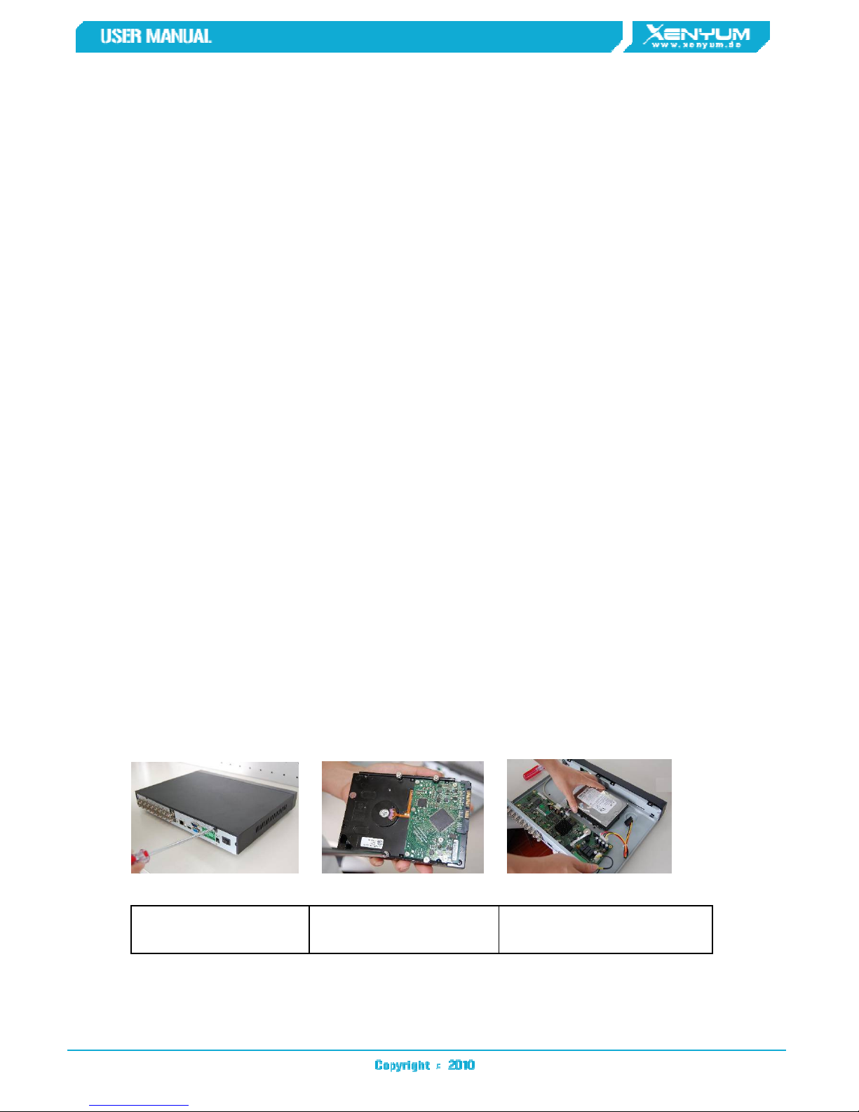
1.4 HDD Installation
This series DVR has only one SATA HDD. Please use HDD of 7200rpm or higher.
You can refer to the User’s Manual for recommended HDD brand.
Please follow the instructions below to install hard disk.
1. Loosen the screws of the
2. Fix four screws in the HDD
3. Place the HDD in accordance with
6
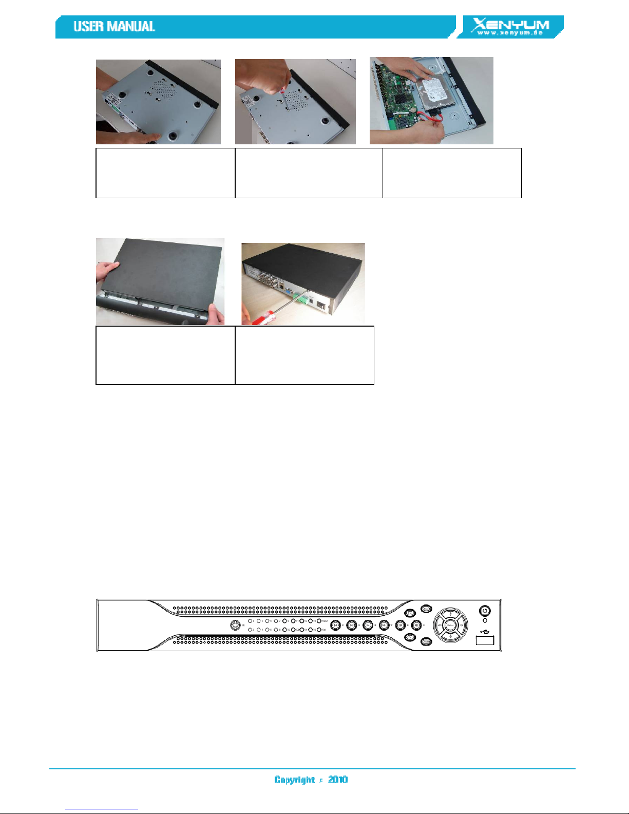
firmly.
4. Turn the device upside down
and then turn the screws in
5. Fix the HDD firmly.
6. Connect the HDD cable and
power cable.
7. Put the cover in accordance
with the clip and then place the
upper cover back.
Note:
You can connect the HDD data cable and the power cable first and then fix the HDD in the
device.
Please pay attention to the front cover. It adopts the vertical sliding design. You need to
push the clip first and then put down.
8. Secure the screws in the
rear panel and the side panel.
1.5 Front Panel
This series product has two types of front panels.
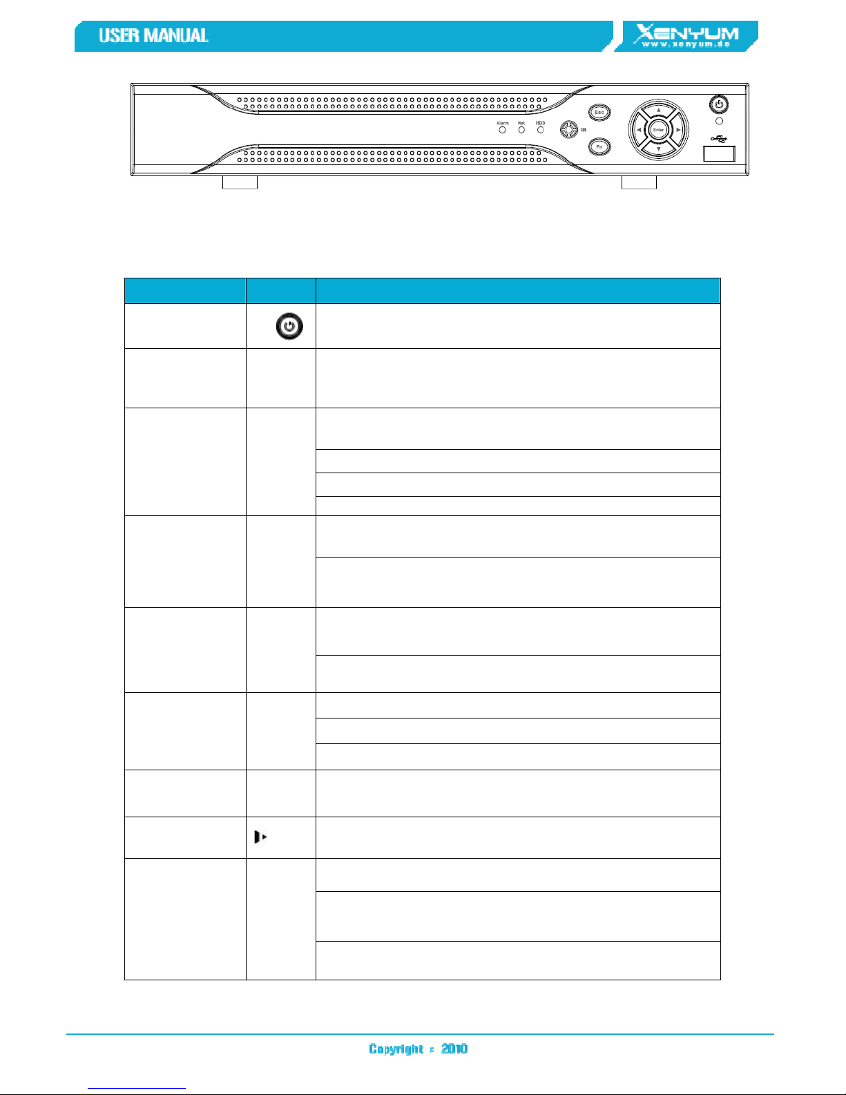
1.5.1 Standard 1U Series
The front panel is shown as in Figure 1-1.
1.5.2 Simple Entry Level Series and Simple Lite Series
The simple entry level and simple lite series is shown as in Figure 1-2.
Figure 1-1
7
Figure 1-2
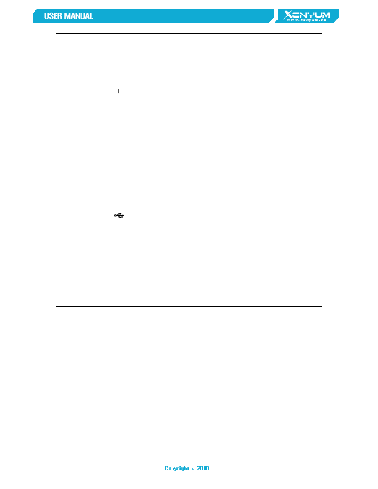
Please refer to the following sheet for front panel button information.
Name Icon Function
Power button
Shift Shift
Up/1
Down/4
Left/2
Right/3
ESC ESC
、
⊳
Power button, press this button for three seconds to boot up
or shut down DVR.
In textbox, click this button to switch between numeral,
English(Small/Capitalized),donation and etc.
Activate current control, modify setup, and then move up
and down.
Increase/decrease numeral.
Assistant function such as PTZ menu.
In text mode, input number 1/4 (English character G/H/I)
Shift current activated control,
When playback, click these buttons to control playback bar.
In text mode, input number 2(English character A/B/C)
/3(English character D/E/F)
Go to previous menu, or cancel current operation.
When playback, click it to restore real-time monitor mode.
Confirm current operation
Enter ENTER
Record REC
Slow play/8
Assistant Fn
Go to default button
Go to menu
Manually stop/start recording, working with direction keys
or numeral keys to select the recording channel.
Multiple slow play speeds or normal playback.
In text mode, input number 8 (English character T/U/V).
One-window monitor mode, click this button to display
assistant function: PTZ control and image color.
Backspace function: in numeral control or text control, press
it for 1.5seconds to delete the previous character before the
cursor.
In motion detection setup, working with Fn and direction
keys to realize setup.
8
In text mode, click it to switch between numeral, English
character(small/capitalized) and etc.
Realize other special functions.
Fast play/7
Play
previous/0
Reverse/Pau
se/6
Play Next/9
Play/Pause /5
USB port
Network
abnormal
indication
light
⊳
Net
Various fast speeds and normal playback.
In text mode, input number 7 (English character P/Q/R/S).
In playback mode, playback the next video
In playback mode, playback the previous video
In text mode, input number 0.
In normal playback or pause mode, click this button to
reverse
playback
In reverse playback, click this button to pause playback.
In text mode, input number 6 (English character M/N/O)
In menu setup, go to down ward of the dropdown list.
In text mode, input number 9 (English character W/X/Y/Z)
In normal playback click this button to pause playback
In pause mode, click this button to resume playback.
In text mode, input number 5(English character J/K/L).
To connect USB storage device, USB mouse.
Network error occurs or there is no network connection, the
light becomes red to alert you.
HDD
abnormal
indication
light
Record light 1-16
IR Receiver IR It is to receive the signal from the remote control.
Alarm
indication
light
HDD
Alarm
HDD error occurs or HDD capacity is below specified
threshold value, the light becomes red to alert you.
System is recording or not. It becomes on when system is
recording.
Here you can view there is external alarm input or not. The
light becomes on when there is an external alarm. The light
become off when the external alarm stops.
1.6 Rear Panel
1.6.1 Standard 1U Series
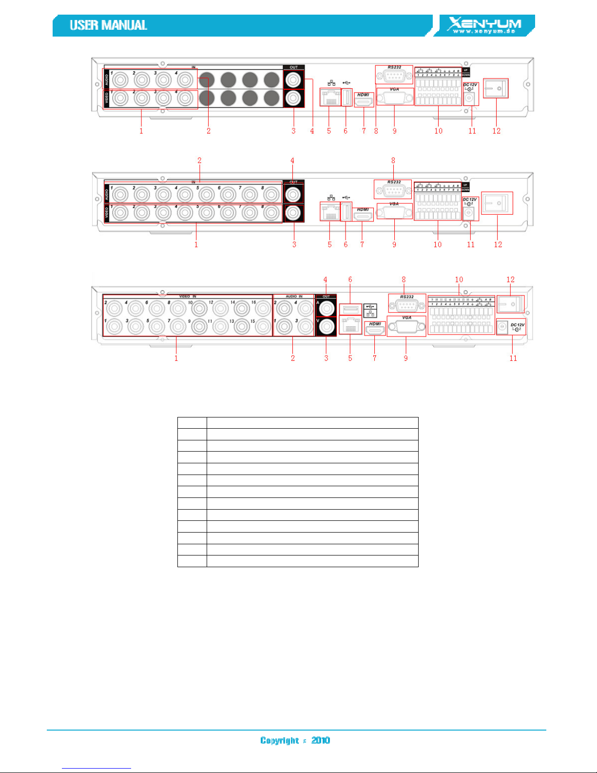
Standard 1U series product rear panel is shown as below. See Figure 1-3 through Figure 1-5.
9
8 RS232 port
Figure 1-3 4-channel
Figure 1-4 8-channel
Figure 1-5 16-channel
Please refer to the following sheet for detailed information.
1 Video input
2 Audio input
3 Video CVBS output
4 Audio output
5 Network port
6 USB port
7 HDMI port
9 Video VGA output
10 Alarm input/alarm output/RS485 port
11 Power input port
12 Power button
1.6.2 Simple Entry Level Series
Simple entry level series real panel (4/8-channel) is shown as below. See Figure 1-6 and Figure
1-7.
 Loading...