

Page 1
- 1 -
Xentino SI305 – SI306
Quick Installation Guide
“focus differently”
www.xentino.com
SI305 – SI306 Industrial Gigabit PoE Ethernet Switch
Quick Installation Guide
Overview
The lite/unmanaged (PoE) Industrial Gigabit Ethernet Switch solutions are designed for supporting
standard industrial applications without complex setup to make the network truly plug-and-play.
Package Checklist
Please verify that the box contains the following items :
Item
Quantity
Xentino Industrial Ethernet Switch
1
Wall-mount plates
2
DIN-Rail CLIP
1
M4 Screws (for the wall mount plates & DIN CLIP)
4
DC power terminal block
1
Safety Instructions
When a connector is removed during installation, testing, or servicing, or when an energized fiber is
broken, a risk of ocular exposure to optical energy that may be potentially hazardous occurs, depending
on the laser output power.
The primary hazards of exposure to laser radiation from an optical-fiber communication system are:
Damage to the eye by accidental exposure to a beam emitted by a laser source.
Damage to the eye from viewing a connector attached to a broken fiber or an energized fiber.
Documentation Conventions
The following conventions are used in this quick installation guide to emphasize information that will be of
interest to the reader.
Danger — The described activity or situation might or will cause personal injury.
Warning — The described activity or situation might or will cause equipment damage.
Caution — The described activity or situation might or will cause service interruption.
Note — The information supplements the text or highlights important points.
Page 2
- 2 -
Xentino SI305 – SI306
Quick Installation Guide
“focus differently”
www.xentino.com
Technical Specifications
The lite/unmanaged (PoE) Industrial Gigabit Ethernet Switch solutions are designed for supporting standard
industrial applications without complex setup to make the network truly plug-and-play.
Model
SI305
SI306
Ethernet
Copper RJ45 Ports (POE)
4 x 10/100/1000 Mbps speed autonegotiation; MDI/MDIX Auto-crossover
4 x 10/100/1000 Mbps speed autonegotiation; MDI/MDIX Auto-crossover
Copper RJ45 Ports(Non POE)
1 x 10/100/1000 Mbps speed autonegotiation; MDI/MDIX Auto-crossover
-
SFP (pluggable) Ports
-
100/1000BaseSFP slot
Fiber port connector
-
LC typically for fiber
PoE
IEEE 802.3at/af PoE PSE
Power
Power input
Redundant Input Terminals
Reverse power protection
Input voltage range
12-58 VDC, 54-58V for PoE+, 48-58V for PoE
Environmental and Compliances
Operating temperature range
-40 to +75°C (cold startup at -40°C)
Storage temperature range
-40 to +85 °C
Humidity
5 to 95% RH (non-condensing)
Mechanical
Ingress protection
IP30
Dimension
136mm(H) x 29mm (W) x 106mm (D) (without DIN rail clip)
Weight
375g
Installation option
DIN-Rail mounting
Wall mounting
Page 3
- 3 -
Xentino SI305 – SI306
Quick Installation Guide
“focus differently”
www.xentino.com
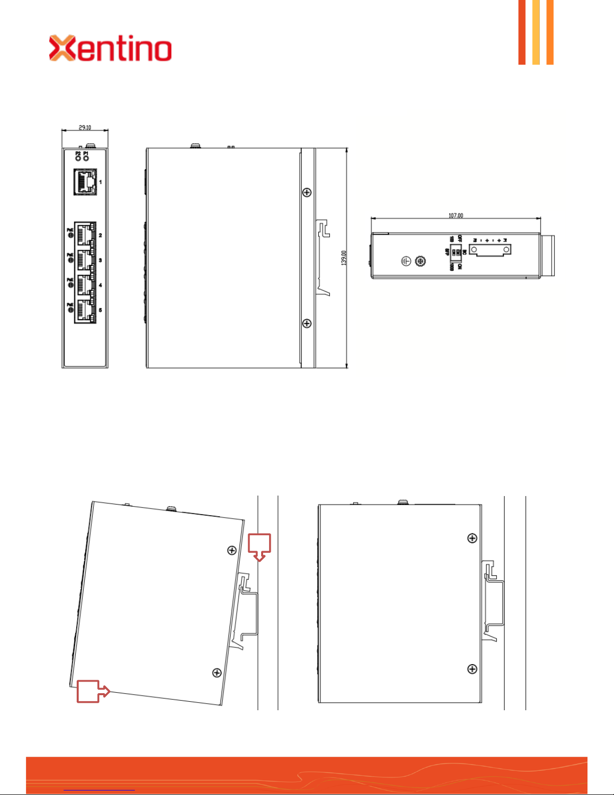
DIN-Rail Mounting
Mounting step:
1. Screw the DIN-Rail bracket on with the bracket and screws in the accessory kit.
2. Hook the unit over the DIN rail.
3. Push the bottom of the unit towards the DIN Rail until it snaps into place.
Dimension Illustration
3
2
Page 4
- 4 -
Xentino SI305 – SI306
Quick Installation Guide
“focus differently”
www.xentino.com
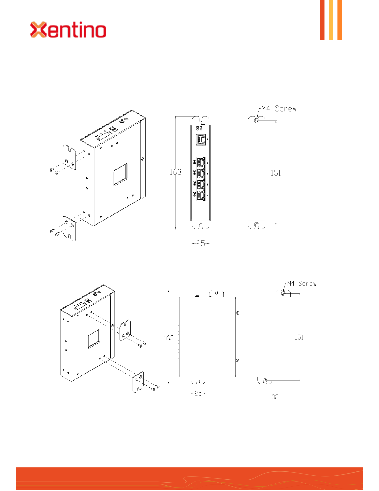
Wall Mounting
Mounting step:
1. Screw on the wall-mount plate on with the plate and screws in the accessory kit.
Page 5
- 5 -
Xentino SI305 – SI306
Quick Installation Guide
“focus differently”
www.xentino.com
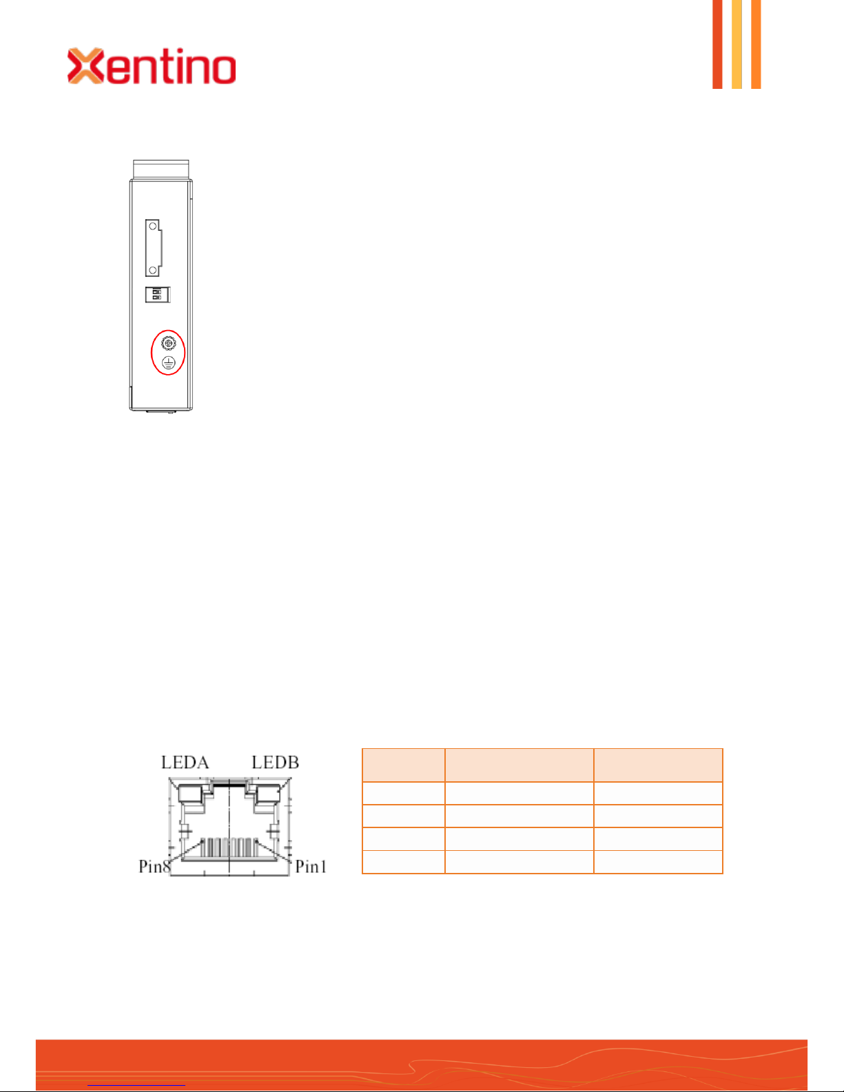
Pin
Assignment
PoE Assignment
1,2
T/Rx+,T/Rx-
Positive V
Port
3,6
T/Rx+,T/Rx-
Negative V
Port
4,5
T/Rx+,T/Rx-
X
7,8
T/Rx+,T/Rx-
X
Ground Connecting
Ethernet Interface Connecting (RJ45 Ethernet)
The switches provide two types of electrical (RJ45) and optical (mini-GBIC) interfaces.
Connecting the Ethernet interface via RJ45:
To connect to a PC, use a straight-through or a cross-over Ethernet cable,
To connect the Xentino SI Series switch to an Ethernet device, use UTP (Unshielded Twisted Pair) or
STP (Shielded Twisted Pair) Ethernet cables.
The pin assignment of RJ-45 connector is shown in the following figure and table.
Xentino SI Series switch must be properly grounded for optimum system
performance.
Page 6
- 6 -
Xentino SI305 – SI306
Quick Installation Guide
“focus differently”
www.xentino.com
DANGER:
Never attempt to view optical connectors that might be emitting laser energy.
Do not power up the laser product without connecting the laser to the optical
fiber and putting the cover in position, as laser outputs will emit infrared laser
light at this point.
Note:
1. The DC power should be connected to a well-fused power supply.
2. Input power should be within the range of 54~58VDC for PoE+ compliant, or 4858VDC for PoE compliant.
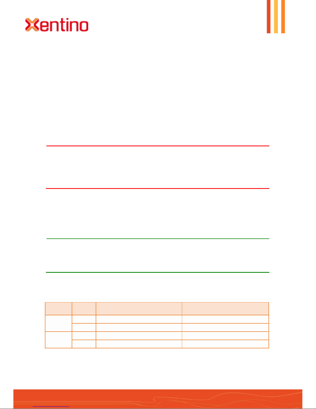
Pin No#
Status
5-Port with PoE (4TX+1TX-PoE)
5-Port (4TX+1SFP) with PoE
Pin 1
ON
To enable Broadcast storm rate limit
To enable Broadcast storm rate limit
OFF
To disable Broadcast storm rate limit
To disable Broadcast storm rate limit
Pin 2
ON
NOT USED
NOT USED
OFF
NOT USED
NOT USED
Ethernet Interface Connecting the (Fiber, SFP)
For a 100 Mbps fiber port available, please prepare the LC connectors or SC connectors (with the use of
an optional SC-to-LC adapter). They are also available with multimode, single mode, long-haul (for
connections up to 120+ km) or special-application transceivers.
For a 1000 Mbps fiber port available, please use the mini-GBIC SFP (small form pluggable). These
accept plug in fiber transceivers that typically have an LC style connector. They are available with
multimode, single mode, long-haul (for connections up to 80+ km) or special-application transceivers.
For each fiber port there is a transmit (TX) and receive (RX) signal. Please make sure that the transmit
(TX) port of the switch connects to the receive (RX) port of the other device, and the receive (RX) port of
the switch connects to the transmit (TX) port of the other device when making your fiber optic
connections.
Power Connecting
The switch can be powered from two power supply (input range 12V – 58V). Insert the positive and
negative wires into V+ and V- contact on the terminal block and tighten the wire-clamp screws to prevent
the wires from being loosened.
DIP Switch Setting
Page 7
- 7 -
Xentino SI305 – SI306
Quick Installation Guide
“focus differently”
www.xentino.com
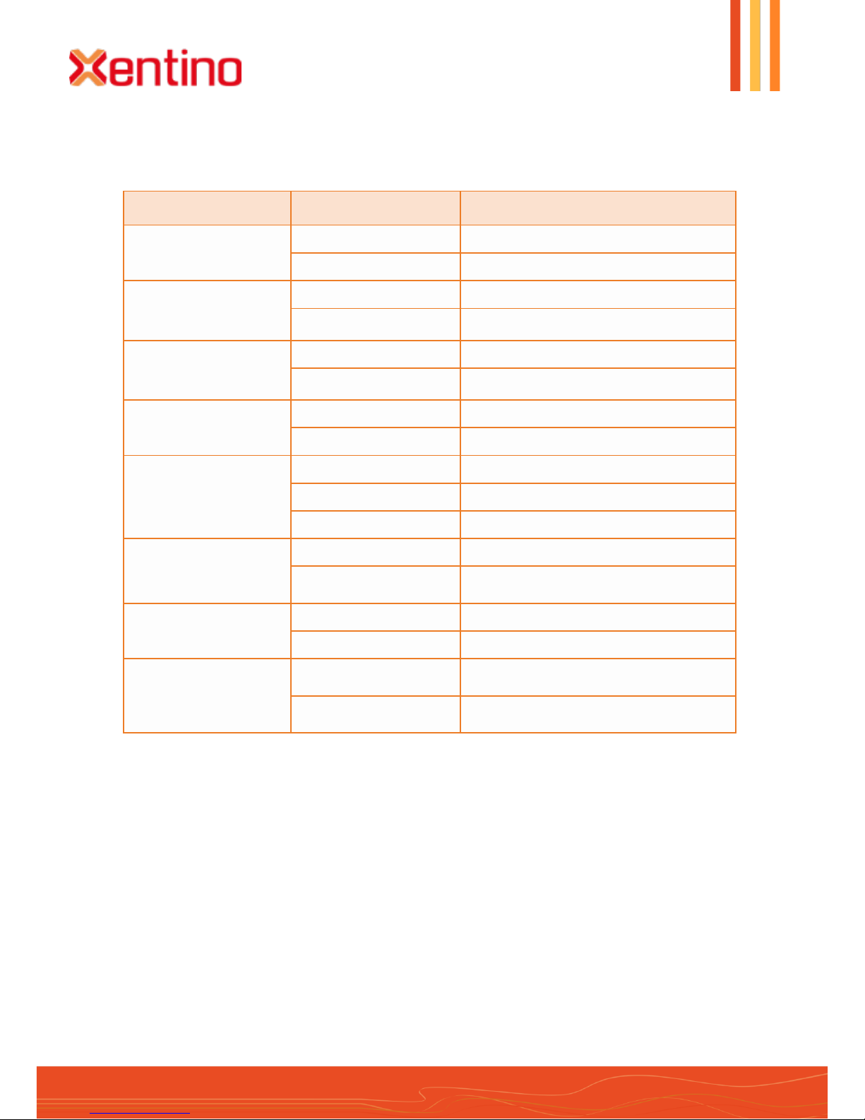
LED Name
Indicator / Color
Condition
PoE
On Green
PoE is working
Off
PoE is not working
P1
On Green
P1 power line has power
Off
P1 power line disconnect or does not have
supply power
P2
On Green
P2 power line has power
Off
P2 power line disconnect or does not have
supply power
Alarm
On Red
Power failure alarm occurs
Off
No power failure alarm
Copper 1 to N port
Link/Act
On Green
Ethernet link up but no traffic is detected
Flashing Green
Ethernet link up and there is traffic detected
Off
Ethernet link down
Copper 1 to N port
Speed
On Yellow
A 1000Mbps connection is detected
Off
No link, a 10Mbps or 100 Mbps connection
is detected
SFP 1 to N port (N=0,1,2)
Link/Act
On Green
Ethernet link up
Off
Ethernet link down
SFP 1 to N port (N=0,1,2)
Speed
On Yellow
SFP port speed 1000Mbps connection is
detected.
Off
No link or a SFP port speed 100Mbps
connection is detected.
LED Status Indications
For more information please visit our website : www.xentino.com
 Loading...