

Page 1
Service Manual
XENON NOVA®300
MODEL 201340 20
Technical
Description and
Service Instructions
for
®
XENON NOVA
300
MODEL 201340 20
Order No. SV3445
Juni 2011-0.10 SM-20-01-V1.6
Page 2

06.11
© All pictures, photos and product descriptions are the intellectual
property of KARL STORZ GmbH & Co. KG
Utilization and copies by third parties have to be authorized by
KARL STORZ GmbH & Co. KG
All rights reserved.
Page 3

XENON NOVA®300
MODEL 201340 20
Contents
Section Title Page
0. General .................................................................................................................. 0-3
1. Instruction Manual .............................................................................................. 1-
2. Physical Design .................................................................................................... 2-
2.1 Exploded views of the XENON NOVA
2.1.1 Exploded view of the XENON NOVA
2.1.2 Spare parts of the XENON NOVA
2.1.3 Exploded view of the XENON NOVA
2.1.4 Spare parts of the XENON NOVA
3. Descriptions of Operation and Circuit Diagrams .............................................. 3-
3.1 Description of operation of the XENON NOVA
3.1.1 General description ................................................................................................ 3-2
3.1.2 Basic features ........................................................................................................ 3-2
3.1.2.1 Manual brightness control ...................................................................................... 3-2
3.1.3 Block diagrams of the XENON NOVA
3.1.3.1 Block diagram of the XENON NOVA
3.1.3.2 Block diagram of the XENON NOVA
3.2 Detailed description of operation .......................................................................... 3-3
3.2.1 Fans ........................................................................................................................ 3-3
3.2.2 Power supply unit .................................................................................................. 3-3
3.2.2.1 Power supply unit (up to serial no. LF0611982) .................................................... 3-3
3.2.2.2 Power supply unit (as from serial no. LF0611983) ................................................ 3-4
3.2.2.3 Circuit diagram of the power supply unit (as from serial no. LF0611983) ............ 3-5
3.2.3 Lamp timer circuit .................................................................................................. 3-6
3.2.3.1 Circuit diagram of the lamp timer board ................................................................ 3-7
3.3 Troubleshooting ...................................................................................................... 3-8
3.3.1 Troubleshooting the XENON NOVA
3.3.2 Component courses of action ................................................................................ 3-9
3.4 Technical data of the XENON NOVA
®
300 .......................................................... 2-2
®
300 (up to serial no. LF0611982) .............. 2-2
®
300 (up to serial no. LF0611982) .................. 2-3
®
300 (as from serial no. LF0611983) .......... 2-4
®
300 (as from serial no. LF0611983) ................ 2-5
®
300 .............................................. 3-2
®
300 .......................................................... 3-2
®
300 (up to serial no. LF0611982) .............. 3-2
®
300 (as from serial no. LF0611983) .......... 3-3
®
300 .............................................................. 3-8
®
300 ............................................................ 3-10
4. Replacement of Individual Assemblies .............................................................. 4-
4.1 Information about replacements ............................................................................ 4-2
4.2 Tools required for replacing the individual assemblies .......................................... 4-2
4.3 Replacement of power supply .............................................................................. 4-3
4.3.1 Replacement of power supply (201340 84) .......................................................... 4-3
4.3.2 Replacement of power supply (Z07854) ................................................................ 4-3
4.4 Replacement of fan assembly ................................................................................ 4-3
4.5 Replacement of lamp ............................................................................................ 4-4
4.6 Replacement of attenuator assembly .................................................................... 4-4
4.7 Replacement of condenser lens ............................................................................ 4-4
4.8 Replacement of the hot mirror assembly .............................................................. 4-4
4.9 Figures for replacements ........................................................................................ 4-6
4.9.1 Figure 1 (up to serial no. LF0611982) .................................................................... 4-6
4.9.2 Figure 1 (as from serial no. LF0611983) ................................................................ 4-7
4.9.3 Figure 2 .................................................................................................................. 4-8
06.11 / V1.6 0-1
Page 4

XENON NOVA®300
MODEL 201340 20
Section Title Page
4.9.4 Figure 3 .................................................................................................................. 4-9
5. Testing and Adjustments .................................................................................... 5-
5.1 Equipment required for the individual settings ...................................................... 5-2
5.2 Test instruments required for the individual adjustment procedures .................... 5-2
5.3 Testing and adjusting the lamp current (up to serial no. LF0611982) .................. 5-2
5.4 Testing and adjusting the lamp current (as from serial no. LF0611983) ................ 5-3
5.5 Focusing the lamp .................................................................................................. 5-3
6. Maintenance and Safety Checks ........................................................................ 6-
6.1 Safety checks ........................................................................................................ 6-2
6.2 Safety devices ........................................................................................................ 6-3
6.3 Maintenance operations ........................................................................................ 6-3
6.3.1 Lamp replacement ................................................................................................ 6-3
6.3.2 Battery replacement .............................................................................................. 6-3
6.3.3 Interior cleaning ...................................................................................................... 6-3
6.4 Servicing and repair .............................................................................................. 6-4
6.5 Fuse replacement .................................................................................................. 6-4
6.6 Cleaning and disinfection ...................................................................................... 6-4
7. Modifications and Supplements ........................................................................ 7-
8. Appendix ................................................................................................................ 8-
Test report - Safety Check .................................................................................... 8-1
0-2 06.11 / V1.6
Page 5

XENON NOVA®300
MODEL 201340 20
0. General
Thank you for your expression of confidence in the KARL STORZ brand name. Like all of our other
products, this product is the result of years of experience and great care in manufacture. You and your
organization have decided in favor of a modern, high-quality piece of equipment from KARL STORZ.
KARL STORZ instruments and equipment are for use only by qualified medical personnel who are
trained in their use. All electrical installations at the location of use should meet applicable national and
local electrical codes.
Refer servicing to duly authorized KARL STORZ service personnel. Always use genuine replacement
parts from KARL STORZ. To determine which replacement parts are required please refer to the
enclosed replacement parts list. Repair and calibration of this device requires special tools and gauges;
certain internal adjustments must not be altered.
For further information, please consult this service manual or contact:
KARL STORZ GmbH & Co. KG Karl Storz Endoscopy-America, Inc.
Mittelstrasse 8, 78532 Tuttlingen 600 Corporate Pointe
PO Box 230, 78503 Tuttlingen Culver City, CA 90230-7600
Germany USA
Phone: +49 (0)7461 708-980 Phone: +1 310 338-8100
Fax: +49 (0)7461 708-404 +1 800 421-0837
E-Mail: info@karlstorz.de Fax: +1 310 410-55 27
Web: www.karlstorz.com
and ask for Technical Services.
Warranty
All KARL STORZ instruments and equipment are warranted to be free from defects in workmanship and
materials for two (2) years from date of sale, unless otherwise specified; any instruments or equipment
with such defects during the applicable warranty period will be promptly repaired or replaced at no
charge to the customer.
KARL STORZ shall not be liable, expressly or implicitly, for:
• Any damages which might arise or be caused, whether by the customer or by any of the users of the
instrument or equipment, as a result of:
– misuse, mishandling, and/or improper operation,
– repairs, modifications and/or alterations performed other than by KARL STORZ or a KARL STORZ
authorized repair facility, or
– use in combination with adaptors and/or equipment, or use in any manner or medical procedure,
other than those for which it is designed; and
• Any special, indirect and/or consequential damages of any kind and however caused arising from the
sale or use of the instrument and/or equipment.
THIS WARRANTY IS IN LIEU OF ALL OTHER WARRANTIES, EXPRESS, IMPLIED, AND/OR STATUTORY,
INCLUDING, BUT NOT LIMITED TO, WARRANTIES OF MERCHANTABILITY, FITNESS, AND/OR OF
SUITABILITY FOR A PARTICULAR PURPOSE, AND OF ALL OTHER OBLIGATIONS OR LIABILITIES ON
KARL STORZ’S PART.
KARL STORZ neither assumes nor authorizes any person to assume for it any other liabilities in
connection with the sale of said instrument and equipment. To insure proper use, handling, and care of
instruments and equipment, consult the applicable product literature, catalog, brochure, instruction
manual, teaching film and other materials which are included with the product and/or otherwise available
from KARL STORZ, at no charge, upon request.
06.11 / V1.6 0-3
Page 6
XENON NOVA®300
MODEL 201340 20
Maintenance and Repair
KARL STORZ recommends that all equipment be checked and inspected once a year by KARL STORZ,
or by an authorized agent. All services such as modifications, repairs, calibrations, and/or readjustments
may only be performed by KARL STORZ or by an authorized agent.
Caution: Repairs may only be performed by qualified technicians trained in electrical or
By making the enclosed technical information available, KARL STORZ does not authorize any service or
repair by unauthorized service personnel. Tampering with the instruments or equipment, or unauthorized
service or repair of the device nullifies and voids the warranty.
electronic engineering, in compliance with the relevant occupational, safety
and accident prevention regulations.
Always unplug the equipment before performing any repairs.
Safety Testing based on IEC 62353, IEC / UL 60601-1, whichever may apply,
must be performed after servicing has been completed.
Reservation of Rights
This documentation is the sole and exclusive property of KARL STORZ and may neither be copied nor
passed on to third parties without the express written authorization and approval of KARL STORZ.
KARL STORZ reserves the right to make engineering modifications in the interest of promoting
technological progress and generating performance improvements without obligation on the part of
KARL STORZ to submit prior notice thereof.
0-4 06.11 / V1.6
Page 7

Section 1.
Instruction Manual
XENON NOVA®300
MODEL 201340 20
06.11 / V1.6
Direction Sign:
Physical Design ➩ 2
Descriptions of Operation and Circuit Diagrams ➩ 3
Replacement of Individual Assemblies ➩ 4
Testing and Adjustments ➩ 5
Maintenance and Safety Checks ➩ 6
Modifications and Supplements ➩ 7
Appendix ➩ 8
Page 8

Page 9

Section 2.
Physical Design
XENON NOVA®300
MODEL 201340 20
06.11 / V1.6
Direction Sign:
➩
1 Instruction Manual
Descriptions of Operation and Circuit Diagrams ➩ 3
Replacement of Individual Assemblies ➩ 4
Testing and Adjustments ➩ 5
Maintenance and Safety Checks ➩ 6
Modifications and Supplements ➩ 7
Appendix ➩ 8
Page 10

Page 11
XENON NOVA®300
MODEL 201340 20
Contents 2. Physical Design
Section Title Page
2. Physical Design .................................................................................................... 2-
®
2.1 Exploded views of the XENON NOVA
2.1.1 Exploded view of the XENON NOVA
2.1.2 Spare parts of the XENON NOVA
2.1.3 Exploded view of the XENON NOVA
2.1.4 Spare parts of the XENON NOVA
300 .......................................................... 2-2
®
300 (up to serial no. LF0611982) .............. 2-2
®
300 (up to serial no. LF0611982) .................. 2-3
®
300 (as from serial no. LF0611983) .......... 2-4
®
300 (as from serial no. LF0611983) ................ 2-5
06.11 / V1.6 2-1
Page 12
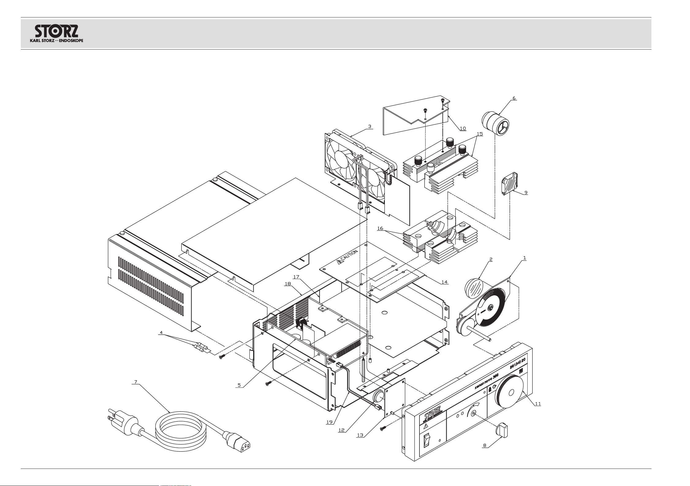
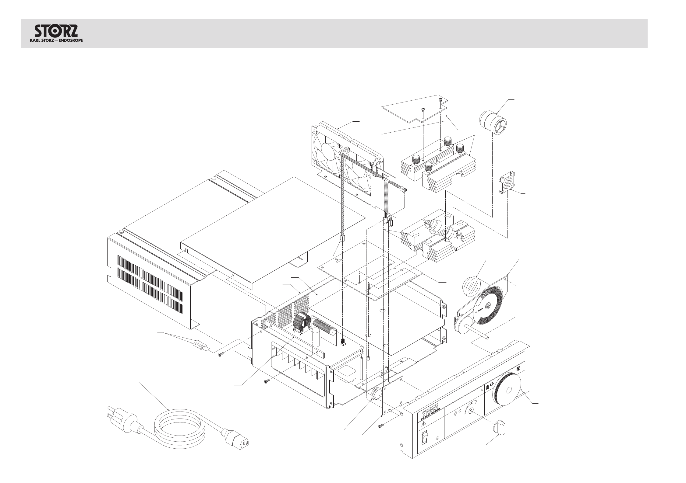
2.1 Exploded views of the XENON NOVA®300
2.1.1 Exploded view of the XENON NOVA®300 (up to serial no. LF0611982)
XENON NOVA®300
MODEL 201340 20
2-2 2-2 06.11 / V1.6
Page 13
XENON NOVA®300
MODEL 201340 20
2.1.2 Spare parts of the XENON NOVA®300 (up to
serial no. LF0611982)
Position Item description Order no.
10
11
12
13
14
15
16
17
18
19
1
–
–
2
3
4
5
6
7
8
9
–
–
–
–
Attenuator assembly, without attenuator disc M19288
Attenuator disc, only
Fixation ring to fix attenuator disc M19288 at axle
Condenser lens
Fan assembly (with connector and mounting rivets)
Fuse 2 x T 3.15 AL / 250 V [220 VAC … 240 VAC]
Fuse 2 x T 6.3 AL / 250 V [100 VAC … 125 VAC]
Power supply unit
Xenon lamp, 300 W
Power cord (with ground lead)
Power cord “hospital grade” (USA)
Brightness control knob (with screw)
Hot mirror assembly
Baffle
Adapter with screwed joint
Battery, timer
Lamp timer board
Lamp board
Heatsink top, front
Heatsink top, rear
Heatsink bottom, front
Heatsink bottom, rear
Nomex barrier
Rear panel assembly
Jumper cable p.s. to lamp timer board
Front panel
Power switch
Housing cover
Standoff for power supply
20131586
M19288
M19431
20131581
20134085
1069600
2027890
20134084
20133028
400A
400B
20131582
20134083
20134090
20134080
20131587
20134091
20134092
20134081
20134082
20134086
20134087
20134093
20134088
20134089
M18365
1163890
M13283
Z07624
Important note:
When ordering replacement parts always provide the following data
Item description Order no.
06.11 / V1.6 2-3
Page 14
2.1.3 Exploded view of the XENON NOVA®300 (as from serial no. LF0611983)
30
0
W
2
1
4
6
7
8
9
10
C
A
U
T
I
ON
3
5
17
18
19
12
13
14
16
15
x
e
n
o
n
n
o
v
a
3
0
0
2
0
1
3
4
0
2
0
11
XENON NOVA®300
MODEL 201340 20
2-4 2-4 06.11 / V1.6
Page 15
XENON NOVA®300
MODEL 201340 20
2.1.4 Spare parts of the XENON NOVA®300 (as from
serial no. LF0611983)
Position Item description Order no.
10
11
12
13
14
15
16
17
18
19
1
–
2
3
4
5
6
7
8
9
–
–
–
–
Attenuator assembly, without attenuator disc M19288
Attenuator disc, only
Condenser lens
Fan assembly (with connector and mounting rivets)
Fuse 2 x T 3.15 AL / 250 V [220 VAC … 240 VAC]
Fuse 2 x T 6.3 AL / 250 V [100 VAC … 125 VAC]
Fuse 2 x T 2.5 AL / 250 V [220 VAC … 240 VAC]
Fuse 2 x T 5.0 AL / 250 V [100 VAC … 125 VAC]
Power supply unit
Xenon lamp, 300 W
Power cord (with ground lead)
Power cord “hospital grade” (USA)
Brightness control knob (with screw)
Hot mirror assembly
Baffle
Adapter with screwed joint
Battery, timer
Lamp timer board
Lamp board
Heatsink top, front
Heatsink top, rear
Heatsink bottom, front
Heatsink bottom, rear
Nomex barrier
Rear panel assembly
Jumper cable p.s. to lamp timer board
Front panel
Power switch
Housing cover
Standoff for power supply
1)
1)
2)
2)
20131586
M19288
20131581
20134085
1069600
2027890
1059700
1222890
Z07854
20133028
400A
400B
20131582
20134083
20134090
20134080
20131587
20134091
20134092
20134081
20134082
20134086
20134087
20134093
20134088
20134089
M18365
1163890
M13283
Z07624
Important note:
When ordering replacement parts always provide the following data
Item description Order no.
1) Valid up to serial no. BC0627707.
2) Valid as from serial no. BC0627829.
06.11 / V1.6 2-5
Page 16

Page 17

XENON NOVA®300
MODEL 201340 20
Section 3.
Descriptions of Operation and
Circuit Diagrams
06.11 / V1.6
Direction Sign:
➩
1 Instruction Manual
➩
2 Physical Design
Replacement of Individual Assemblies ➩ 4
Testing and Adjustments ➩ 5
Maintenance and Safety Checks ➩ 6
Modifications and Supplements ➩ 7
Appendix ➩ 8
Page 18

Page 19

XENON NOVA®300
MODEL 201340 20
Contents 3. Descriptions of Operation and Circuit
Diagrams
Section Title Page
3. Descriptions of Operation and Circuit Diagrams .............................................. 3-
®
3.1 Description of operation of the XENON NOVA
3.1.1 General description ................................................................................................ 3-2
3.1.2 Basic features ........................................................................................................ 3-2
3.1.2.1 Manual brightness control ...................................................................................... 3-2
3.1.3 Block diagrams of the XENON NOVA
3.1.3.1 Block diagram of the XENON NOVA
3.1.3.2 Block diagram of the XENON NOVA
®
300 .......................................................... 3-2
®
300 (up to serial no. LF0611982) .............. 3-2
®
300 (as from serial no. LF0611983) .......... 3-3
3.2 Detailed description of operation .......................................................................... 3-3
3.2.1 Fans ........................................................................................................................ 3-3
3.2.2 Power supply unit .................................................................................................. 3-3
3.2.2.1 Power supply unit (up to serial no. LF0611982) .................................................... 3-3
3.2.2.2 Power supply unit (as from serial no. LF0611983) ................................................ 3-4
3.2.2.3 Circuit diagram of the power supply unit (as from serial no. LF0611983) ............ 3-5
3.2.3 Lamp timer circuit .................................................................................................. 3-6
3.2.3.1 Circuit diagram of the lamp timer board ................................................................ 3-7
3.3 Troubleshooting ...................................................................................................... 3-8
3.3.1 Troubleshooting the XENON NOVA
®
300 .............................................................. 3-8
3.3.2 Component courses of action ................................................................................ 3-9
3.4 Technical data of the XENON NOVA
®
300 ............................................................ 3-10
300 .............................................. 3-2
06.11 / V1.6 3-1
Page 20

XENON NOVA®300
MODEL 201340 20
3.1 Description of operation of the XENON NOVA®300
3.1.1 General description
The 201340 20 XENON NOVA®300 is a 300 W Xenon light source designed for use in general
endoscopic surgery, especially where high light levels may be needed, and where cine, video, or still
photographic documentation may be required.
The Xenon lamp color temperature approximates bright sunlight and is considered unmatched for visual
and photographic color rendition. Full intensity is reached almost immediately without a warm-up period.
The XENON NOVA
manually adjusted by an opto-mechanical attenuator. This assures the greatest range of light-to-dark
without arc instability problems.
Refer to the Section 1. Instruction Manual for operating warnings and cautions.
®
300 operates at a constant power level (about 300 W) while the brightness is
3.1.2 Basic features
3.1.2.1 Manual brightness control
The brightness can be manually adjusted using a brightness control knob.
3.1.3 Block diagrams of the XENON NOVA®300
3.1.3.1 Block diagram of the XENON NOVA®300 (up to serial no. LF0611982)
3-2 06.11 / V1.6
Page 21

XENON NOVA®300
+
-
POWER SUPPLY
CON 1
6.3 A
E
L
N
CON 1 CON 2 CON 3 RV2
MODEL 201340 20
3.1.3.2 Block diagram of the XENON NOVA®300 (as from serial no. LF0611983)
3.2 Detailed description of operation
3.2.1 Fans
The fans are 12 V DC fans, with power supplied by the power supply.
3.2.2 Power supply unit
3.2.2.1 Power supply unit (up to serial no. LF0611982)
A 300 W power supply unit (order no. 201340 84) is used for the power supply to the electronics. This
type PS300-11 power supply unit is authorized for use in medical devices. The conformity is
documented with the following test numbers:
– CE, UL2601-1/IEC60601-1, CSA 22-2 No. 601-1
(UL File #EL 93746, Project 99 SC 47645)
– Medical Electrical Equipment, Part 1: General Requirements for Safety
06.11 / V1.6 3-3
Page 22

XENON NOVA®300
MODEL 201340 20
3.2.2.2 Power supply unit (as from serial no. LF0611983)
A 300 W power supply unit (order no. Z07854) is used for the power supply to the electronics. This
power supply unit is authorized for use in medical devices.
3-4 06.11 / V1.6
Page 23

3.2.2.3 Circuit diagram of the power supply unit (as from serial no. LF0611983)
XENON NOVA®300
MODEL 201340 20
06.11 / V1.6 3-5
Page 24

XENON NOVA®300
MODEL 201340 20
3.2.3 Lamp timer circuit
The lamp timer circuit keeps track of lamp usage in hours, and warns the operator that a scheduled
lamp change is approaching or overdue. The red LED (D902) on the front panel will light at approximately
450 hours (90% of the lamp’s expected life) and start blinking at around 500 hours to indicate a lamp
change is imperative. Upon changing the lamp, the user must manually reset the timer by pressing the
reset switch located inside the light source on the front panel. The circuit power is maintained by a
lithium battery when the light source is not in use. The battery must be replaced every 10 years to insure
continued operation.
The first stage of the lamp timer circuit consists of a CD4060 binary counter (U1) driven by a 20 kHz
crystal (Y1). The CD4060 counter divides the 20 kHz crystal frequency down to a 1.22 Hz square wave at
U1-3, which provides clocking for the next stage of the counter. When the light source is in use, the
yellow LED (D1) will blink to indicate the circuit is running. A test jumper is also provided to reduce the
overall 500 hour count to about 30 minutes for testing purposes. This section of the circuitry is powered
by the +12 V bias supply output and is only active when the light source is in use.
The second stage of the lamp timer circuit consists of two CD4020 binary counters, a CD4017 decade
counter, a lithium battery (BAT) and a reset switch (SW). These counters are driven by the 1.22 Hz square
wave from the first stage of the counter circuit and keep track of lamp usage hours. Pins 9 and 11 of the
CD4017 decade counter (U4) provide the logic signals that activate the FET’s that control the replace
lamp LED (D3). The lithium battery powers this section of the circuitry at all times, whether the light
source is on or not. When pressed, the reset switch sets all three counters back to zero.
The final stage of the lamp timer circuit consists of 3 FET’s (Q1–Q3), the replace lamp LED (D3), and the
LED current-limiting resistor (R7). At approximately 450 hours U4-9 goes high and activates the Q2 FET
which turns on the replace lamp LED (D902). At approximately 500 hours U903-9 goes low and U903-11
goes high, activating Q3. Since Q3 is in series with Q1, and Q1 is continuously clocked by U1-3 at a
1.22 Hz rate, the replace lamp LED will start to blink. In addition, when U4-11 goes high, it disables pin
13 of the CD4017 which is the count-enable pin, preventing any additional counting of the CD4017
counter (U4). This holds the count at 500 hours until the SW RESET switch is pressed. Since this stage
of the circuit is powered by the +12 V bias supply output, the replace lamp LED and associated circuitry
do not draw power from the lithium battery.
3-6 06.11 / V1.6
Page 25

3.2.3.1 Circuit diagram of the lamp timer board
XENON NOVA®300
MODEL 201340 20
06.11 / V1.6 3-7
Page 26

XENON NOVA®300
MODEL 201340 20
3.3 Troubleshooting
3.3.1 Troubleshooting the XENON NOVA®300
Device won’t power up
– Check the power cord and connections. Replace if necessary.
– Check for blown power fuse. See Fuse blown.
– Check power source. See Power source.
Device suddenly shut down
– Make sure the fans are working and vents are unobstructed. If the fans are not working, see Fans will
not run.
– Measure the lamp wattage, see General complaint of low brightness. If it is not between
235 W … 300 W, replace the lamp power supply.
Fuse blown
– Indication of a power supply component failure (probably the FETS).
Fans will not run
– Check the fans itself. Replace if necessary.
– Check the 12 VDC output from the power supply and all connections.
Lamp will not start or stay lit
– Replace the lamp with a known good one.
Note: There is not necessarily a visible indication of age or noticeable difference between a Xenon
– Check for blown power fuse. See Fuse blown.
– Check the power supply.
lamp that is new and one with thousands of hours on it. It is good practice to discard old
Xenon lamps rather than to keep them around as spares. Old lamps may cause erratic
starting, flickering, and generally poor operation.
Light cannot be dimmed properly
– Check the light attenuator mechanism for jammed or broken parts. Replace if necessary.
General complaint of low brightness (up to serial no. LF0611982)
– Examine all other parts in the optical system, including the light guide cable, the endoscope, the video
camera and lenses.
– Measure the power (in W) required by the lamp. Measure the voltage across the RV2 resistor and
multiply the value by 100. Measure the voltage across the lamp. Multiply these two values together to
find the lamp power. The power requirement should be at least 235 W, but not more than 300 W. If the
lamp power is 235 W … 300 W, and the light output is too low, replace the lamp.
– Replace the lamp.
– Replace the power supply.
Caution: Lamps are high pressure vessels and must be handled with care. When
Caution: Connect the voltmeter only when the lamp is already started; otherwise, the
handling the lamp wear safety glasses and face shields to protect the face
and gloves to prevent skin oil transfer. Never touch the porcelain insulator on
the lamp with bare hands. When working with an operating lamp, wear eye
and face protection to prevent blindness or UV damage.
high-voltage starting pulse will damage or destroy the voltmeter. Do not
restart the device when making measurements.
3-8 06.11 / V1.6
Page 27

XENON NOVA®300
MODEL 201340 20
General complaint of low brightness (as from serial no. LF0611983)
– Examine all other parts in the optical system, including the light guide cable, the endoscope, the video
camera and lenses.
– Measure the power (in W) required by the lamp. Measure the voltage across the RV2 resistor and
multiply the value by 100. Measure the voltage across the lamp. Multiply these two values together to
find the lamp power. The power requirement should be at least 235 W, but not more than 300 W. If the
lamp power is 235 W … 300 W, and the light output is too low, replace the lamp.
Caution: Lamps are high pressure vessels and must be handled with care. When
Caution: Connect the voltmeter only when the lamp is already started; otherwise, the
handling the lamp wear safety glasses and face shields to protect the face
and gloves to prevent skin oil transfer. Never touch the porcelain insulator on
the lamp with bare hands. When working with an operating lamp, wear eye
and face protection to prevent blindness or UV damage.
high-voltage starting pulse will damage or destroy the voltmeter. Do not
restart the device when making measurements.
Replace lamp indicator lights before 450 hours have elapsed
– Check to see if the counters have been reset.
Light-cable input-end burning
– Check for inadequate cleaning of the cable, or use of a previously burned cable.
– Unsuitable light-guide; that is, a light-guide only suitable for low power use.
3.3.2 Component courses of action
Lamp
– If the lamp fails before 500 hours, look for the following items to ensure no other problems were
responsible. Replace the lamp.
• Check for marked discoloration inside the lamp (usually caused by a seal leak).
• Check for a cracked window (caused by thermal shock).
• Check for a crazed or burned reflector. This can be caused by overheating or overcurrent, and is
indicative of problems elsewhere.
Light attenuator
– Check for a jammed attenuator wheel or a broken part. Replace if necessary.
– Lamp timer circuit
A problem may be evident either through the non-operation of the front panel LED or a gross error in
the timing (e.g., the replace lamp timer board).
• If the replace lamp indicator lights before 450 hours have elapsed, inspect U4.
06.11 / V1.6 3-9
Page 28

3.4 Technical data of the XENON NOVA®300
XENON NOVA®300 201340 20
XENON NOVA®300
MODEL 201340 20
Supply voltage
Power frequency
Power consumption
Power fuses
3)
100 VAC … 125 VAC / 220 VAC … 240 VAC, 앐10%
50 Hz … 60 Hz
700 VA
3)
/ 450 VA
4)
2 x T 3.15 AL / 250 V (220 VAC … 240 VAC)
2 x T 6.3 AL / 250 V (100 VAC … 125 VAC)
Power fuses
4)
2 x T 2.5 AL / 250 V (220 VAC … 240 VAC)
2 x T 5.0 AL / 250 V (100 VAC … 125 VAC)
Lamp type
Lamp voltage
Lamp current
Wattage
Color temperature
Operating temperature
Dimensions (w x h x d)
Weight
Xenon lamp, 300 W
14 VDC (nominal)
21 A, 앐2 A
300 W (nominal)
6000 K (initial)
10 °C … 40 °C (50 °F … 104 °F)
305 mm x 101 mm x 240 mm
4.0 kg
Storage and transport conditions:
Storage temperature
Humidity
Atmospheric pressure
-10 °C … 60 °C (14 °F … 140 °F)
5% … 95%, rel. humidity, non-condensing
500 hPa … 1080 hPa
Standard compliance
According to IEC 60601-1, IEC 60601-2-18, UL 60601-1, CAN/CSA C22.2 No. 601.1-M90:
Type of protection against electric shocks: Protection Class I
Degree of protection against electric shocks: Applied part of type CF
According to IEC 60601-1-2:2001:
Please read the Electromagnetic Compatibility Information in the appendix of the instruction
manual.
Directive compliance
According to Medical Device Directive (MDD):
Medical device in Class I
This medical device bears the CE mark according to MDD 93/42/EEC. A code number after the CE mark
indicates the responsible notified body.
3) Valid up to serial no. BC0627707.
4) Valid as from serial no. BC0627829.
3-10 06.11 / V1.6
Page 29

XENON NOVA®300
MODEL 201340 20
Section 4.
Replacement of Individual Assemblies
06.11 / V1.6
Direction Sign:
➩
1 Instruction Manual
➩
2 Physical Design
➩
3 Descriptions of Operation and Circuit Diagrams
Testing and Adjustments ➩ 5
Maintenance and Safety Checks ➩ 6
Modifications and Supplements ➩ 7
Appendix ➩ 8
Page 30

Page 31

XENON NOVA®300
MODEL 201340 20
Contents 4. Replacement of Individual Assemblies
Section Title Page
4. Replacement of Individual Assemblies .............................................................. 4-
4.1 Information about replacements ............................................................................ 4-2
4.2 Tools required for replacing the individual assemblies .......................................... 4-2
4.3 Replacement of power supply .............................................................................. 4-3
4.3.1 Replacement of power supply (201340 84) .......................................................... 4-3
4.3.2 Replacement of power supply (Z07854) ................................................................ 4-3
4.4 Replacement of fan assembly ................................................................................ 4-3
4.5 Replacement of lamp ............................................................................................ 4-4
4.6 Replacement of attenuator assembly .................................................................... 4-4
4.7 Replacement of condenser lens ............................................................................ 4-4
4.8 Replacement of the hot mirror assembly .............................................................. 4-4
4.9 Figures for replacements ........................................................................................ 4-6
4.9.1 Figure 1 (up to serial no. LF0611982) .................................................................... 4-6
4.9.2 Figure 1 (as from serial no. LF0611983) ................................................................ 4-7
4.9.3 Figure 2 .................................................................................................................. 4-8
4.9.4 Figure 3 .................................................................................................................. 4-9
06.11 / V1.6 4-1
Page 32

XENON NOVA®300
MODEL 201340 20
4.1 Information about replacements
The device is fully adjusted and tested before it leaves the manufacturers. If the device fails, a test of the
assemblies should be carried out by authorized KARL STORZ technical staff.
4.2 Tools required for replacing the individual assemblies
– Power supply
Phillips screwdriver, medium
Needle nose pliers
Conductive work mat, wristband, ground cable
– Fan assembly
Phillips screwdriver
Needle nose pliers
Standard screwdriver
Conductive work mat, wristband, ground cable
– Lamp
Phillips screwdriver, medium
Torx driver and assorted bits
Thermal compound
Conductive work mat, wristband, ground cable
– Attenuator assembly
Phillips screwdriver
Torx driver and assorted bits
Needle nose pliers
Standard screwdriver
M3 hex wrench
Conductive work mat, wristband, ground cable
– Condenser lens
Phillips screwdriver
Torx driver and assorted bits
Needle nose pliers
Standard screwdriver
M3 hex wrench
Conductive work mat, wristband, ground cable
– Hot mirror assembly
Torx driver and assorted bits
Conductive work mat, wristband, ground cable
Caution: Always unplug the device from the power supply before carrying out any
repairs on it!
After servicing, a safety test or the leakage current and protective ground
resistance measurements according to IEC 62353, IEC / UL 60601-1, CAN /
CSA C22.2 NO 601.1, whichever may apply, are to be carried out.
To prevent damage to the components caused by the build-up of electrostatic
charges, we recommend that you connect yourself to ground via the
wristband throughout servicing.
4-2 06.11 / V1.6
Page 33

XENON NOVA®300
MODEL 201340 20
4.3 Replacement of power supply
4.3.1 Replacement of power supply (201340 84)
Refer to Section 4.9 Figures for replacements – figures 1 and 2.
a. Disconnect the light source from its power source.
b. Remove the outer cover by sliding the interlock slide to the right, removing the four screws on the
bottom of the case, and sliding the cover back.
c. Remove the power supply cover by removing the screws holding it in place.
d. Remove the front panel assembly by removing the four screws with the T10 driver and pulling the
front panel assembly forward.
e. Disconnect the input wires and the lamp leads.
f. Remove the screws holding the power supply on the bottom and the side of the device.
g. Unplug the lamp timer board.
h. Carefully lift the power supply out of the case.
i. Unplug the fan connector from the power supply.
j. Replace the power supply and reassemble in reverse order of disassembly.
Caution: Make sure that the top and bottom halves of the heat sink are aligned so that
the lamp can be fitted free of distortion.
4.3.2 Replacement of power supply (Z07854)
Refer to Section 4.9 Figures for replacements – figures 1 and 2.
a. Disconnect the light source from its power source.
b. Remove the outer cover by sliding the interlock slide to the right, removing the four screws on the
bottom of the case, and sliding the cover back.
c. Remove the power supply cover by loosen the screws holding it in place.
d. Remove the front panel assembly by removing the four screws and pulling the front panel assembly
forward.
e. Disconnect the input wires and the lamp leads.
f. Remove the screws holding the power supply on the bottom of the device.
g. Unplug the lamp timer board.
h. Carefully lift the power supply out of the case.
i. Unplug the fan connector from the power supply.
j. Transfer the standoffs to the new power supply.
k. Replace the power supply and reassemble in reverse order of disassembly.
Caution: Make sure that the top and bottom halves of the heat sink are aligned so that
the lamp can be fitted free of distortion.
4.4 Replacement of fan assembly
Refer to Section 4.9 Figures for replacements – figure 1.
a. Disconnect the lamp leads from the power supply.
b. Unplug the fan wires from the lamp timer board.
c. Remove the two screws at the bottom of the device holding the fan assembly.
d. Remove the screws holding the rear panel and pull the panel back slightly from the device.
e. Remove the fan assembly.
f. Replace the fan and reassemble in reverse order of disassembly.
Caution: Switch the device off and disconnect it from the electrical power line before
06.11 / V1.6 4-3
undertaking any work on the device.
Page 34

XENON NOVA®300
MODEL 201340 20
4.5 Replacement of lamp
Refer to Section 4.9 Figures for replacements – figures 1 and 2.
a. Disconnect the light source from its power source.
b. Remove the outer cover by sliding the interlock slide to the right, removing the four screws on the
bottom of the case, and sliding the cover back.
c. Lift the lamp insulator and fold it back.
d. Unscrew the four heat sink thumbscrews.
e. Carefully remove the upper half of each heatsink. Remove the old lamp.
Caution: Lamps are high pressure vessels and must be handled with care. When
f. Apply a thin coating of thermal joint compound around the inside circumference of the heatsinks
(both anode and cathode) as well as on the anode end surface.
g. Reassemble in reverse order of disassembly.
Note: It is recommended that new lamps be used for eight hours in the light source prior to clinical
use if purchased from a source other than KARL STORZ.
handling the lamp wear safety glasses and face shields to protect the face
and gloves to prevent skin oil transfer. Never touch the porcelain insulator on
the lamp with bare hands.
4.6 Replacement of attenuator assembly
Refer to Section 4.9 Figures for replacements – figures 1 and 3.
a. Disconnect the light source from its power source.
b. Remove the outer cover by sliding the interlock slide to the right, removing the four screws on the
bottom of the case, and sliding the cover back.
c. Remove the front panel assembly by removing the four screws with the T10 driver and pulling the
front panel forward.
d. Remove the brightness control knob by removing the set screw with an M3 hex wrench.
e. Remove the two retaining screws holding the attenuator assembly to the posts and remove the
assembly, sliding the post for the knob out of its hole.
f. Replace the attenuator assembly and reassemble in reverse order of disassembly.
4.7 Replacement of condenser lens
Refer to Section 4.9 Figures for replacements – figures 1 and 3.
a. Remove the attenuator assembly as described in Section 4.6 Replacement of attenuator assembly.
b. Remove the three retaining screws holding the lens.
c. Replace the condenser lens and reassemble in reverse order of disassembly. Tighten the retaining
screws a little at a time, moving in a circular pattern in order to keep the correct orientation of the
lens. Avoid overtightening the screws.
4.8 Replacement of the hot mirror assembly
Refer to Section 4.9 Figures for replacements – figures 1 and 2.
a. Disconnect the light source from its power source.
b. Remove the outer cover by sliding the interlock slide to the right, removing the four screws on the
bottom of the case, and sliding the cover back.
c. Lift the lamp insulator and fold it back.
d. Unscrew the thumbscrews on the heat sinks.
e. Carefully remove the upper half of the heatsinks and the lamp as described in Section 4.6
Replacement of attenuator assembly. f. Remove the nuts holding the bottom front heatsink. g. Bend tabs holding the hot mirror assembly in place.
4-4 06.11 / V1.6
Page 35

XENON NOVA®300
MODEL 201340 20
h. Lift the hot mirror assembly out of the lower heat sink slot and replace with the new hot mirror
assembly.
Caution: The hot mirror assembly is secured against falling out by two retaining clips in
i. Reassemble in reverse order of disassembly.
the bottom part of the heat sink. Bend back the retaining clips at the front
and remove the filter.
06.11 / V1.6 4-5
Page 36

4.9 Figures for replacements
4.9.1 Figure 1 (up to serial no. LF0611982)
XENON NOVA®300
MODEL 201340 20
4-6 4-6 06.11 / V1.6
Page 37

4.9.2 Figure 1 (as from serial no. LF0611983)
30
0
W
C
A
U
T
I
ON
x
e
n
o
n
n
o
v
a
3
0
0
2
0
1
3
4
0
2
0
XENON NOVA®300
MODEL 201340 20
06.11 / V1.6 4-7
Page 38

4.9.3 Figure 2
XENON NOVA®300
MODEL 201340 20
4-8 4-8 06.11 / V1.6
Page 39

4.9.4 Figure 3
XENON NOVA®300
MODEL 201340 20
06.11 / V1.6 4-9
Page 40

Section 5.
Testing and Adjustments
XENON NOVA®300
MODEL 201340 20
06.11 / V1.6
Direction Sign:
➩
1 Instruction Manual
➩
2 Physical Design
➩
3 Descriptions of Operation and Circuit Diagrams
➩
4 Replacement of Individual Assemblies
Maintenance and Safety Checks ➩ 6
Modifications and Supplements ➩ 7
Appendix ➩ 8
Page 41

Page 42

XENON NOVA®300
MODEL 201340 20
Contents 5. Testing and Adjustments
Section Title Page
5. Testing and Adjustments .................................................................................... 5-
5.1 Equipment required for the individual settings ...................................................... 5-2
5.2 Test instruments required for the individual adjustment procedures .................... 5-2
5.3 Testing and adjusting the lamp current (up to serial no. LF0611982) .................. 5-2
5.4 Testing and adjusting the lamp current (as from serial no. LF0611983) ................ 5-3
5.5 Focusing the lamp .................................................................................................. 5-3
06.11 / V1.6 5-1
Page 43

XENON NOVA®300
MODEL 201340 20
5.1 Equipment required for the individual settings
Note: The device is fully adjusted and tested by the manufacturer. Readjustments should be
performed by qualified personnel only. Opening the equipment or performance of any repairs
or modifications of the equipment by unauthorized persons shall relieve KARL STORZ GmbH
& Co. KG of any liability for its performance. Any such opening, repair, or modification
performed during the warranty period shall void all warranty.
Lamp current is the only recommended adjustment and may be performed when a new lamp
is installed, but is normally necessary only after repairing the power supply.
5.2 Test instruments required for the individual
adjustment procedures
– Digital voltmeter (DVM)
– Small flat blade screwdriver
– Torx screwdriver with assorted bits
– Current probe
5.3 Testing and adjusting the lamp current (up to serial
no. LF0611982)
a. Disconnect the power cord from the light source.
b. Remove the outer cover by sliding the interlock slide to the right, removing the four screws on the
bottom of the case, and sliding the cover back.
c. Lift the lamp insulator and fold it back.
d. Reconnect the power cord and turn the device power on.
Caution: Do not look into the lamp or light cable. Do not allow light from either the light
Caution: Lamps are high pressure vessels and must be handled with care. When
Caution: Connect the voltmeter only when the lamp is already started; otherwise, the
e. Connect the DVM across the lamp. Measure and record the lamp voltage.
f. Lamp power (the product of current and voltage) should be around 300 W. Set the current probe to
10 mV/A, place current probe on lamp return (-) wire and adjust the lamp current to 0.19 V (앐 0.01) /
19 A or to a value that would result the 300 W power requirement. The current adjustment
potentiometer is RV2 on the power supply.
g. Remove the DVM from the circuit and turn off the power.
h. Reassemble in reverse order of disassembly.
source or the light-cable to shine directly on hands or other areas of the body;
burns may occur.
handling the lamp wear safety glasses and face shields to protect the face
and gloves to prevent skin oil transfer. Never touch the porcelain insulator on
the lamp with bare hands. When working with an operating lamp, wear eye
and face protection to prevent blindness or UV damage.
high-voltage starting pulse will damage or destroy the voltmeter. Do not
restart the device when making measurements.
Caution: Always unplug the device from the power supply before carrying out any
5-2 06.11 / V1.6
repairs on it!
After servicing, a safety test or the leakage current and protective ground
resistance measurements according to IEC 62353, IEC / UL 60601-1, CAN /
CSA C22.2 NO 601.1, whichever may apply, are to be carried out.
To prevent damage to the components caused by the build-up of electrostatic
charges, we recommend that you connect yourself to ground via the
wristband throughout servicing.
Page 44

XENON NOVA®300
MODEL 201340 20
5.4 Testing and adjusting the lamp current (as from serial no. LF0611983)
a. Disconnect the power cord from the light source.
b. Remove the outer cover by sliding the interlock slide to the right, removing the four screws on the
bottom of the case, and sliding the cover back.
c. Lift the lamp insulator and fold it back.
d. Reconnect the power cord and turn the device power on.
Caution: Do not look into the lamp or light cable. Do not allow light from either the light
Caution: Lamps are high pressure vessels and must be handled with care. When
Caution: Connect the voltmeter only when the lamp is already started; otherwise, the
e. Connect the DVM across the lamp. Measure and record the lamp voltage.
f. Lamp power (the product of current and voltage) should be around 300 W. Set the current probe to
10 mV/A, place current probe on lamp return (-) wire and adjust the lamp current to 0.19 V (앐 0.01) /
19 A or to a value that would result the 300 W power requirement. The current adjustment
potentiometer is R58 on the power supply.
g. Remove the DVM from the circuit and turn off the power.
h. Reassemble in reverse order of disassembly.
source or the light-cable to shine directly on hands or other areas of the body;
burns may occur.
handling the lamp wear safety glasses and face shields to protect the face
and gloves to prevent skin oil transfer. Never touch the porcelain insulator on
the lamp with bare hands. When working with an operating lamp, wear eye
and face protection to prevent blindness or UV damage.
high-voltage starting pulse will damage or destroy the voltmeter. Do not
restart the device when making measurements.
5.5 Focusing the lamp
a. The focus of the XENON NOVA®300 is fixed at the factory; no adjustment is necessary.
06.11 / V1.6 5-3
Page 45

Page 46

XENON NOVA®300
MODEL 201340 20
Section 6.
Maintenance and Safety Checks
06.11 / V1.6
Direction Sign:
➩
1 Instruction Manual
➩
2 Physical Design
➩
3 Descriptions of Operation and Circuit Diagrams
➩
4 Replacement of Individual Assemblies
➩
5 Testing and Adjustments
Modifications and Supplements ➩ 7
Appendix ➩ 8
Page 47

Page 48

XENON NOVA®300
MODEL 201340 20
Contents 6. Maintenance and Safety Checks
Section Title Page
6. Maintenance and Safety Checks ........................................................................ 6-
6.1 Safety checks ........................................................................................................ 6-2
6.2 Safety devices ........................................................................................................ 6-3
6.3 Maintenance operations ........................................................................................ 6-3
6.3.1 Lamp replacement ................................................................................................ 6-3
6.3.2 Battery replacement .............................................................................................. 6-3
6.3.3 Interior cleaning ...................................................................................................... 6-3
6.4 Servicing and repair .............................................................................................. 6-4
6.5 Fuse replacement .................................................................................................. 6-4
6.6 Cleaning and disinfection ...................................................................................... 6-4
06.11 / V1.6 6-1
Page 49

XENON NOVA®300
MODEL 201340 20
6.1 Safety checks
We recommend carrying out safety checks at least once a year.
Note: To document the result of the safety check use a test report, see Section 8. Appendix.
Work to be carried out Remark
쐽 Visual inspection
– Housing and accessories
– Inscriptions, manufacturer’s identification
plate data
– CE mark, KARL STORZ inspection label
– Instruction manual
– Power fuses
– Fuse label
쐽쐽
Test for proper operation
– Power switch
– Power supply
– Lamp replacement
– Light cable
– Manual intensity control
– Fans
5)
no external damage
correct, legible, clean, wipeable, securely attached
fixed to the housing
present
correct ratings, undamaged, securely positioned
applied next to fuse holder, correct fuse ratings
functions perfectly within the stated voltage range
(100 VAC … 125 VAC / 220 VAC … 240 VAC)
easy to perform
can be inserted easily into the corresponding
socket, engages easily into detented position
brightness adjustment knob
쐽쐽
Electric safety measurements
(IEC 62353)
– Protective ground resistance:
(with power cord) 울 0.3 액
– Earth leakage current: 울 1.00 mA
– Touch current: 울 0.50 mA
– Patient leakage current: 울 0.05 mA
– Patient leakage current: 울 0.05 mA
(line voltage on the applied part)
5) For correct fuse ratings see Section 3.4 Technical data of the XENON NOVA®300.
6-2 06.11 / V1.6
Page 50

XENON NOVA®300
MODEL 201340 20
6.2 Safety devices
For further information about safety devices and instructions please see instruction manual.
6.3 Maintenance operations
Performance of preventive maintenance is not essential. Regular maintenance can, however, contribute
to identifying potential problems before they become serious, thus enhancing the instrument’s reliability
and extending its useful operating life.
Maintenance services can be obtained from your local representative or from the manufacturer.
Regardless of the accident prevention regulations or testing intervals for medical instruments prescribed
in different countries, we recommend a safety check of the device at least once a year.
6.3.1 Lamp replacement
When the lamp has operated for 450 hours (90% of the warranted life of 500 hours) a red “lamp
warning” indicator will light on the front panel. At 500 hours, the lamp warning indicator will blink
continuously until the lamp hours counter is reset. For lamp replacement instructions, see Section 4.5
Replacement of lamp. It is recommended that new lamps purchased from a source other than
KARL STORZ GmbH & Co. KG should be operated for eight hours in the light source prior to clinical use.
6.3.2 Battery replacement
Disassemble the light source as necessary, until the battery may be accessed, see Section 4.6
Replacement of attenuator assembly.
Remove the lamp timer board. The battery connections are soldered in place and must be unsoldered to
be replaced. Alternatively replace the lamp timer board.
Reassemble in the reverse order.
6.3.3 Interior cleaning
Depending on the cleanliness of the operating environment, removal of dust from the interior of the
device may be required periodically. Remove the outer cover and power supply cover as described in
Section 4.3.1 Replacement of power supply (201340 84) or Section 4.3.2 Replacement of power supply
(Z07854). Blow dust from the device using compressed air, taking care not to direct air at the fan blades
or the attenuator screen. Reinstall the covers.
06.11 / V1.6 6-3
Page 51

XENON NOVA®300
MODEL 201340 20
6.4 Servicing and repair
Defective equipment should be serviced and repaired by factory trained technicians and replacement
parts must be ordered from KARL STORZ.
Third party substitutions may result in noncompliance of this product with its original specifications.
KARL STORZ maintains a repair and replacement warehouse which is normally adequate to ensure
prompt replacement of damaged telescopes and instruments. Under the repair and replacement plan,
you receive an identical as-new instrument and are only charged the repair costs for the defective
instrument. For telescopes, you receive a guarantee of 1 year, and for instruments 6 months.
For fiberscopes and equipment, individual repair is necessary. Usually to bridge the repair period, you
will receive a device on loan which you then return to KARL STORZ as soon as you receive the repaired
device.
In Germany you can refer repairs direct to our service hotline
Phone: +49 (0)7461 708-980
Fax: +49 (0)7461 708-404
or
KARL STORZ GmbH & Co. KG
Repair Service Dept.
Dr. Karl-Storz-Str. 34
D-78532 Tuttlingen
In other countries please contact your local KARL STORZ branch or authorized dealer.
6.5 Fuse replacement
For detailed information please see instruction manual.
6.6 Cleaning and disinfection
For detailed information please see instruction manual.
6-4 06.11 / V1.6
Page 52

XENON NOVA®300
MODEL 201340 20
Section 7.
Modifications and Supplements
06.11 / V1.6
Direction Sign:
➩
1 Instruction Manual
➩
2 Physical Design
➩
3 Descriptions of Operation and Circuit Diagrams
➩
4 Replacement of Individual Assemblies
➩
5 Testing and Adjustments
➩
6 Maintenance and Safety Checks
Appendix ➩ 8
Page 53

Page 54

Section 8.
Appendix
XENON NOVA®300
MODEL 201340 20
06.11 / V1.6
Direction Sign:
➩
1 Instruction Manual
➩
2 Physical Design
➩
3 Descriptions of Operation and Circuit Diagrams
➩
4 Replacement of Individual Assemblies
➩
5 Testing and Adjustments
➩
6 Maintenance and Safety Checks
➩
7 Modifications and Supplements
Page 55

Page 56

Article number
Serial number
Visual inspection
Housing and accessories
Labeling
Identification plate data
Power fuses
5)
Fuse label
Electrical safety
Protective ground resistance
(with power cord)
m 0.30 h
Earth leakage current m 1.00 mA
Touch current m 0.50 mA
Patient leakage current m 0.05 mA
Patient leakage current
(line voltage at applied part)
m 0.05 mA
Proper operation
Power switch
Power supply 100 VAC … 125 VAC /
220 VAC … 240 VAC
Light cable
Manual intensity control
Fans
Date
Checked by
Signature
Test report - Safety Check
XENON NOVA®300
MODEL 201340 20
5) For correct fuse ratings see Section 3.4 Technical data of the XENON NOVA®300.
06.11 / V1.6 8-1
Caution: After servicing, a safety test or the leakage current and protective ground
resistance measurements according to IEC 62353, IEC / UL 60601-1, CAN /
CSA C22.2 NO 601.1, whichever may apply, are to be carried out.
Page 57

Page 58

Page 59

KARL STORZ GmbH & Co. KG
Mittelstraße 8, 78532 Tuttlingen/Germany
Postfach 230, 78503 Tuttlingen/Germany
Phone: +49 (0)7461 708-0
Fax: +49 (0)7461 708-105
E-Mail: info@karlstorz.de
Web: www.karlstorz.com
KARL STORZ
Endoscopy-America, Inc.
600 Corporate pointe
Culver City, CA 90230-7600, USA
Phone: +1 310 338-8100
Fax: +1 310 410-55 27
KARL STORZ
Endoscopy Canada Ltd.
2345 Argentia Road, Suite 100
Mississauga, Ontario L5N 8K4 Canada
Phone: +1 905 816-8100
Fax: +1 905 858-0933
KARL STORZ Endoscopia
Latino-America, Inc.
815 N. W. 57th Avenue, Suite 480
Miami, FL 33126-2042, USA
Phone: +1 305 262-8980
Fax: +1 305 262-8986
+1 800 421-0837
+1 800 268-4880
 Loading...