

XENO XDR range Installation And User Manual
Installation and User Manual
for XDR Range of
Digital Video Recorders

INSTALLATION & SAFEGUARDS
All the safety and operating instructions should be read before operation.
Environment Condition for Installation
1. To prevent electric shock or other hazard, do not expose this unit to rain, moisture or dust.
2. Place this unit in a well-ventilated place and do not place heat-generating objects on this
unit.
3. This unit should not be located in an area where it is likely to be subjected to mechanical
shocks.
Before You Start
1. Ensure the power switch is in the OFF position prior to installation.
2. Opening or removing the cover may expose you to dangerous voltage or other hazards.
3. Operate this unit within the range of room temperature and humidity.
4. Supply power through the type of power source indicated on the manufacturer’s label and
w
ith th
e power supply included in
thi
s unit.
5. Keep this unit out of direct sunlight and heat.
6. Make sure conductive material does not go into the fan hole.
Notice
1. Before initial configuration or operation, first set TIME/DATE and then set this unit to the
FACTORY DEFAULT
setting
and finally clear the HDD
.
Follow these steps in order
.
Otherwise it may cause the HDD not to record or save setting value. Or it may record, but
you will not be able to search recorded data.
2. This unit is compatible with large sized HDD.
3. When setting RECORDING SETUP after installation, always set RECORD
CONFIGURATION and SCHEDULE SETUP. Setting Schedule setup is necessary as this
unit records according to Record type & Schedule setup. The default setting value for
Schedule setup is Continuous mode
.
Sc edu e setup s Co t uous ode
4. Stop recording before powering off this unit by entering setup menu. Powering off while
recording may cause critical malfunctions such as Recording Error, Playback Error or System
Error.
CE Mark
A Declaration of Conformity in accordance with the following EU standards has been made.
The manufacturer declares that the product supplied with this document is compliant the
provisions of the EMC Directive 89/336 EEC, the Low Voltage Directive LVD 73/23, the CE
Marking Directive 93/68 EEC and all associated amendments.
2

Table of Contents
CHAP. 1
Features and Package Contents
-------------------------------------------------------- 5
1-1.
Features
-------------------------------------------------------- 5
1-2.
Package Contents & Description
-------------------------------------------------------- 6
CHAP. 2
Function of Buttons
-------------------------------------------------------- 7
2-1.
Front Panel
-------------------------------------------------------- 7
2-2.
Rear Panel
-------------------------------------------------------- 9
2-3. Connector Pin -------------------------------------------------------- 10
CHAP. 3
Installation
-------------------------------------------------------- 12
3-1
.
Confi
guration
--------------------------------------------------------
12
3-2.
Detailed Configuration
-------------------------------------------------------- 13
CHAP. 4
Display Configuration
-------------------------------------------------------- 16
4-1.
Current Status
-------------------------------------------------------- 17
4-2
.
Displ
ay Status
--------------------------------------------------------
17
4-3.
Popup Menu
-------------------------------------------------------- 18
4-4.
Toolbar
-------------------------------------------------------- 22
CHAP. 5
DVR Setup
-------------------------------------------------------- 23
5-1
.
Operation
--------------------------------------------------------
23
5-2.
System
-------------------------------------------------------- 26
5-3.
Network
-------------------------------------------------------- 34
5-4.
Devices
-------------------------------------------------------- 38
5-5.
Record
-------------------------------------------------------- 46
5-6
.
Event
--------------------------------------------------------
52
CHAP. 6
Search
-------------------------------------------------------- 57
6-1.
Calendar Search
-------------------------------------------------------- 57
6-2.
Event Search
-------------------------------------------------------- 59
-
--------------------------------------------------------
6
3
.
Bookmark Search
61
3

CHAP. 7
DVR Operation
----------------------------------------------------------
62
7-1. Live Monitoring ---------------------------------------------------------- 62
7-2. Event Monitoring ---------------------------------------------------------- 66
7-3. Mouse Operation ---------------------------------------------------------- 67
7-4. Record ---------------------------------------------------------- 68
7-5. Audio ---------------------------------------------------------- 68
7-6. Search ---------------------------------------------------------- 68
7-7. Playback ---------------------------------------------------------- 71
7-8. Network Setup ---------------------------------------------------------- 73
CHAP. 8 Integrated Remote Station ---------------------------------------------------------- 84
8-1. IRS Setup ---------------------------------------------------------- 84
8-2. IRS Operation ---------------------------------------------------------- 86
8-3. Remote Viewer ---------------------------------------------------------- 89
8-4.S
earc
h
----------------------------------------------------------
90
8-5. Backup ---------------------------------------------------------- 93
8-6. Player ---------------------------------------------------------- 96
Appendix A Frequently Asked Questions ---------------------------------------------------------- 99
Appendix B Map of Screens ---------------------------------------------------------- 100
Appendix C Factory Default Settings ---------------------------------------------------------- 101
Appendix D HDD Calculation ---------------------------------------------------------- 108
Appendix E Specification ---------------------------------------------------------- 109
Appendix F
Remote Control
----------------------------------------------------------
111
4

CHAPTER 1. Features and Package Contents
1-1. Features
Live Display
PIP (Picture in Picture), Freeze, Zoom, Sequence, PTZ function
1/4/6/8/9/13/16 Split display
Record
Picture image quality setup in 4 steps
Schedule recording / Holiday setup
Event recording by alarm and motion detection
Panic recording
Video Loss detection
BOOKMARK function
4ch Audio record
Pre-Event recording
Network
Monitoring, Setup, Search and Backup
DDNS support
E-mail notification
Playback
Easy search and playback by Date/Time, Event and Bookmark
Various playback speed (forward/Backward)
Backup
Data import/export via USB (Import /Export DVR settings)
Backup via USB or CD/DVD-RW
Network backu
p
p
Others
Simple and easy menu control with popup menu via mouse control
Multi-Language (English, French, Spanish, Italian, Portuguese, Dutch, Russian, Turkish and Polish)
Password lock
NTSC/PAL auto detection
Remote control
SPOT monitor
5

1-2. Package contents
1. Digital Video Recorder
2. Remote Control
IR
ALARM BOOKMARK
3. Power Cable
4. Power Adapter
5. User’s Manual
6. Software CD
7. Rubber Pad
8. HDD Absorber 9. Batteries
10. Rack Mount Bracket,
HDD Bolts
11. Mouse
6

CHAPTER 2. FUNCTION BUTTONS
2-1. Front Panel
1
2
3
4
5
6 7
8
NO
Name Function
1 LED Indicating operation status
<Note>
This manual covers the 4 channel, 8 channel and 16 channel digital video recorders. For simplicity,
the illustrations and descriptions in this manual refer to the 16 channel model.
gp
2 ALARM Panic recording (Press ALARM and channel button together. The selected
channel will begin record in Panic recording mode)
3 Function Key MSC Switch screen division from full screen to 16 split screen
(in 1, 4, 6, 8, 9, 13, 16 sequence )
PIP
Picture In Picture mode
SEQ
Auto camera image sequence in full screen mode
PRESET
Press PRESET and channel button(1~16) together for Preset of PTZ
control
PTZ
Switch LIVE mode to PTZ control mode
SEARCH
Search recorded data on HDD
K
eep pressing the
SEARCH butt
on for a few seconds to begin
playback directly
MENU
Enter SYSTEM MENU
AUDIO
Press AUDIO and channel button(1~4) together for Audio channel On.
Press AUDIO button alone to turn audio off.
MONITOR
Switch screen between Spot and Monitor
STOP
Stop for panic recording & playback, return to schedule recording,
cancel selected function key
4 BOOKMARK Bookmark
7
No Name Function
5 Direction Key Navigate in the menu (while playback)
OK/PAUSE/
FRZ
MENU(OK), LIVE(FREEZE), PLAY(PAUSE)
LEFT Backward playback (In FRZ mode: Step Backward)
RIGHT Forward Playback (In FRZ mode: step Forward)
UP Increase playback speed
(Press AUDIO and UP button together for audio volume up)
DOWN Decrease playback speed
(Press AUDIO and Down button together for audio volume
down)
6 USB Port For recorded data backup and firmware upgrade
7 Camera Selection
/ PTZ Control
1~16 Button : Select camera channel in full screen mode
AUDIO + 1~4 Button : Select audio channel
1, + ZOOM IN
2
,
- ZOOM OUT
,
8 CD/DVD-RW For recorded data backup and firmware upgrade
8

7
2-2. Rear Panel
123
4511
10
6
8
9
No Name Function
1 RS485 Connection with PTZ Camera or other external devices using RS485
<Note>
You cannot mix NTSC and PAL equipment. For example you cannot use a PAL camera and a NTSC
monitor.
RELAY Output Relay Output terminal
SENSOR Input Sensor Input terminal
2 VGA VGA Output to CRT or TFT LCD Monitors
3 ETHERNET Connection to Ethernet devices
4 RS232C Connection to external devices such as PC using RS232C to control DVR
5 CAMERA Connection with NTSC/PAL Cameras
6 LOOP Camera Loop out
7 MONITOR Connection with NTSC/PAL Composite Monitor
8 SPOT Connection for Spot monitor
9 DC Power DC 12V 6.67A Adaptor
10 PS2 Mouse Connection to PS2 Mouse
11 Audio I/O Audio input/output & Microphone input
9

2-3. Connector Pin
[1] RS232
No Details No Details
1 N/C (Normal Close) 6 N/C (Normal Close)
2 RxD (Data Transmission) 7 N/C (Normal Close)
Connection with PC to view and control DVR.
3 TxD (Data Transmission) 8 N/C (Normal Close)
4 N/C (Normal Close) 9 N/C (Normal Close)
5 GND (Ground)
[2] VGA
VGA monitor output port to view screen via PC.
No Details No Details
1 Red Sig.(75Ω, 0.7 p-p) 9 N/C (Normal Close)
2 Green Sig.(75Ω, 0.7 p-p) 10 GND (Ground)
3 Blue Sig.(75Ω, 0.7 p-p) 11 GND (Ground)
4 N/C (Normal Close) 12 N/C (Normal Close)
5 GND
(
Ground
)
13 HYNC (Horizontal Sync.
)
()
(y)
6 GND (Ground) 14 VSYNC (Vertical Sync.)
7 GND (Ground) 15 N/C (Normal Close)
8 GND (Ground)
No Details No Details
1 TX+ (Data Transmission) 5 N/C (Normal Close)
[3] LAN
2
TX-(Data Transmission)
6
R/X-(Data Transmission)
3 RX+ (Data Transmission) 7 N/C (Normal Close)
4 N/C (Normal Close) 8 N/C (Normal Close)
10

[4] CAMERA input & LOOP output
[5] AUDIO
Camera Input
Loop Output
AIN1 ~ AIN 4: Audio Input CH1 ~ CH4
MIC: Microphone Input
AOUT: Audio Output
[6] RELAY OUT
Connection with PTZ camera, sensor, relay output.
No Details No Details No Details
3
7
12 17 221 26
1
RS485 D
-
10
ALARM D14
19
ALARM D7
2 RS485 D+ 11 ALARM D13 20 ALARM D6
3 GND 12 GND 21 ALARM D5
4 RELAY COM 13 ALARM D12 22 GND
5 RELAY NC 14
A
LARM D11 23
A
LARM D4
6 RELAY NO 15 ALARM D10 24 ALARM D3
7 GND 16 ALARM D9 25 ALARM D2
8 ALARM D16 17 GND 26 ALARM D1
9 ALARM D15 18 ALARM D8
11
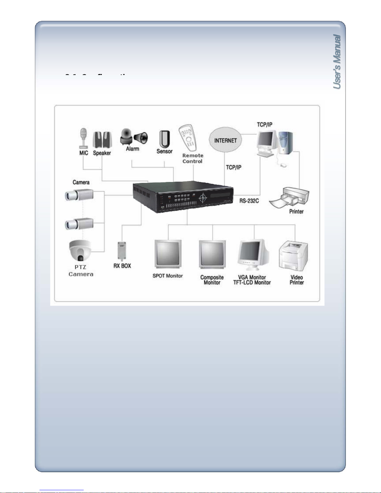
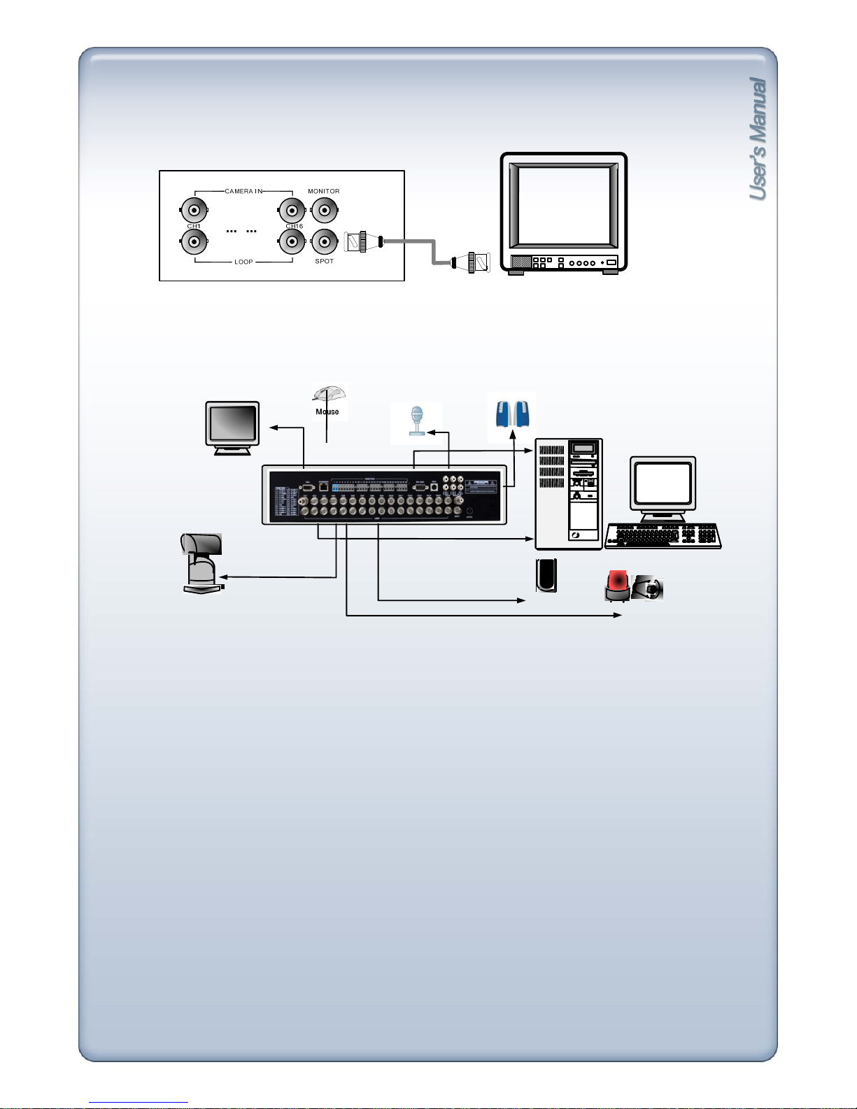
CHAPTER 3. INSTALLATION
3-1. Confi
guration
[Typical DVR Installation]
12
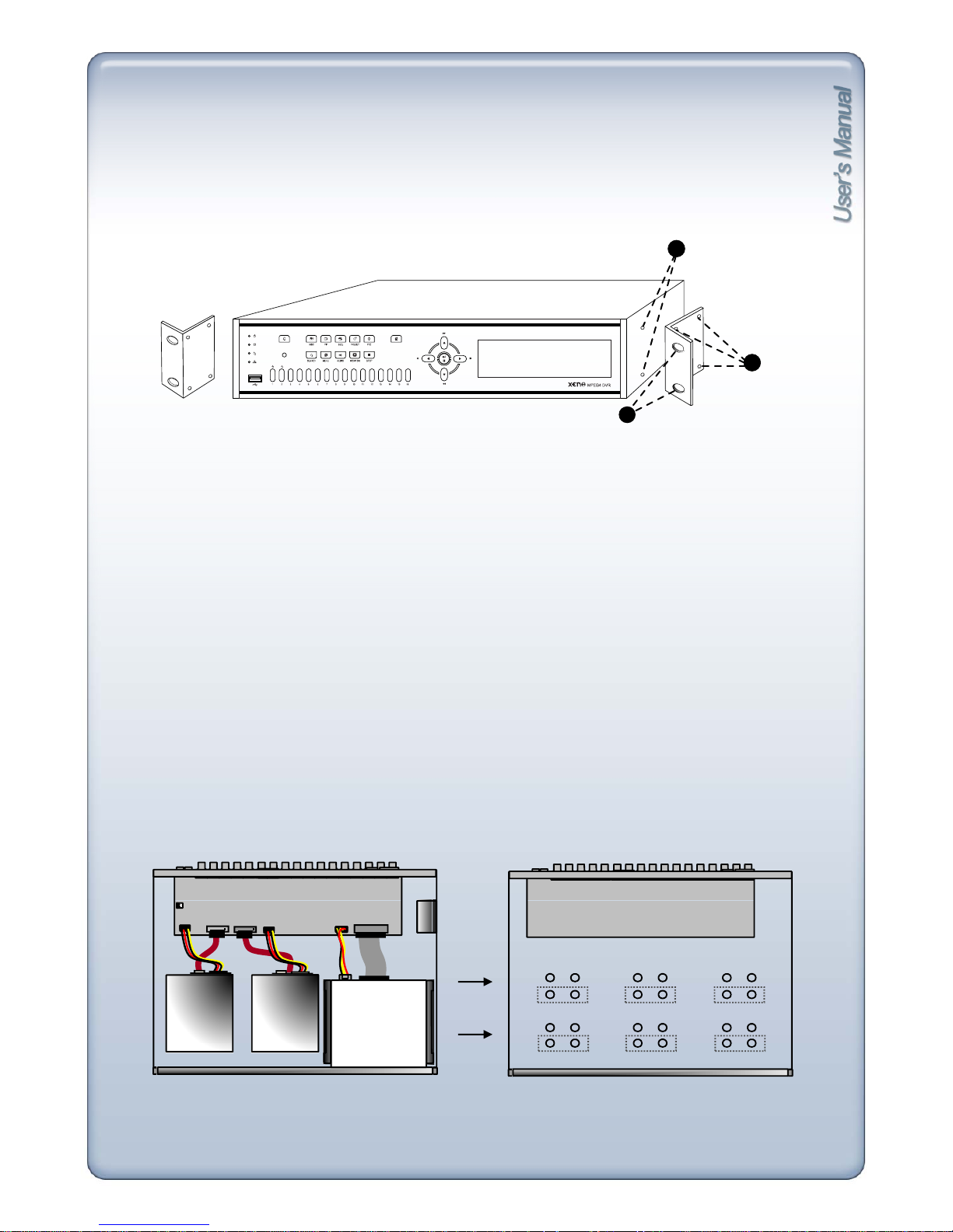
3-2. Detailed Configuration
1) Rack mount
1
1. Remove all 4 bolts on side caps.
IR
ALARM BOOKMARK
2
3
2) HDD (Hard Disk Drive) connection
2. Attach Rack mount bracket to DVR.
3. Attach DVR with rack mount bracket to 19” Rack.
1. Connect Main Board and HDD1 using SATA cable and HDD power cable.
2. When you use just one HDD, install the HDD onto HDD1 location.
3. When you use two HDDs, install the first HDD onto HDD1 location and then install the second
HDD onto HDD2 location in order.
4. Stick the HDD absorber (included in the package) on the bottom of case and then install the HDD
on top of them by using the bolts (included in the package).
HDD Cable Connection
HDD Fix
5. Screws must be inserted from outside of the case bottom.
CD- RW
(
MASTER
)
MAIN BOARD
HDD1
(
MASTER
1)
HDD2
(
MASTER
2)
HDD1 HDD2
MAIN BOARD
x
x
x
x
x
x
x
x
x
x
x
x
13

[3] Camera
VIDEO
LENS
VIDEO
DC
AC24V/DC12
V.P
DC
LEVEL
Rear view of CAMERA
Connect cameras to the camera input on rear panel of DVR marked CAMERA IN.
[4] Monitor
VIDEO A VIDEO CVIDEO B
IN OUT IN OUTIN OUT
Connect the video output marked MONITOR to VIDEO-IN of Main Monitor.
[5] Power Cable
Connect DC 12V, 6.67A Adaptor.
Before turning on, be sure all necessary devices such as Power adaptor,
cameras and Monitor are connected
prop
erly to the DVR!
This unit is for DC 12V. Inadequate supply of power may cause breakdown.
<Note>
pp y
14
qppyp y
Be sure to power off DVR when connecting external devices.
[6] SPOT
SPEAKER
MIC
Connect with the spot monitor as needed.
[7] OTHERS
VGA
MONITOR
PC
PC
SENSOR
SIREN
PTZ
CAMERA
PAN /TILT
CAMERA
RS232C : Control DVR through RS232C port by using PC.
RS485 : Control external device such as PTZ Cameras.
(Pin No.1 ~ 2 at Terminal Block).
RELAY Output : (Pin No.4 ~6 at Terminal Block).
SENSOR Input : (Pin No.8 ~ 11 / No.13 ~ 16 / No.18 ~ 21 / No.23 ~ 26
at Terminal Block).
GND : Ground (Pin No.3 / No.7 / No.12 / No.17 / No.22
at Terminal Block).
ETHERNET
: Connection to LAN, WAN and
Internet
.
VGA : Connection to VGA Monitor (CRT, TFT LCD Monitor)
Resolution is set to 800x600 60 Hz
User can change resolution in DEVICES/ DISPLAY SETUP /
VGA SETUP / VGA RESOLUTION.
Audio Input : Microphone Input (A IN1 ~ A IN4)
Audio Output : Speaker Output (1ch OUT)
Microphone
Input :
Microphone Input
(MIC)
15
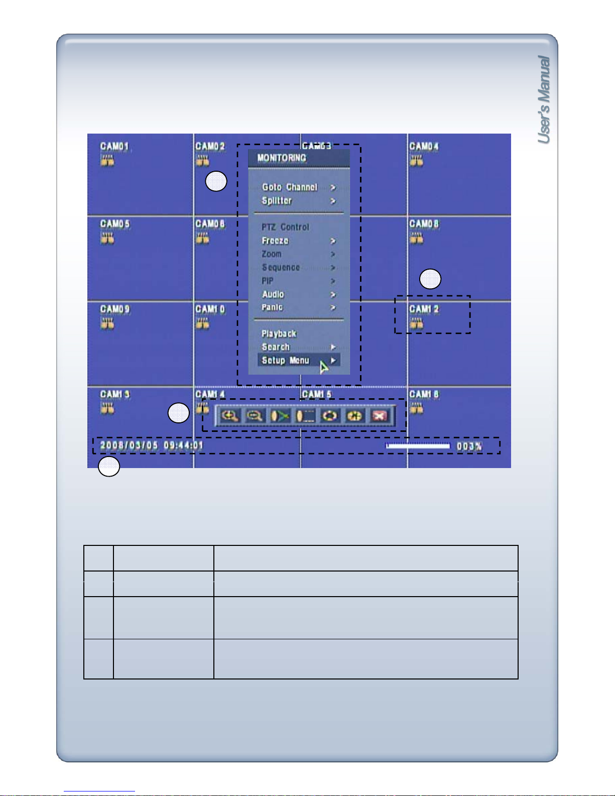
CHAPTER 4. Display Configuration
3
2
1
4
1
Current Status
Date/Time, HDD, Playback
2
Display Status
Displ
ay status icons
3
Popup Menu
Monitoring popup menu in live mode
Playback popup menu in playback mode
PTZ control popup menu in PTZ mode
4
Toolbar
Playback toolbar, PTZ toolbar
16
[1]
Date/Time
4-1. Current Status
[]
[2] HDD
Live mode : Shows current date & time
Playback mode : Shows recorded date & time of the playback image
Live mode : HDD recorded space is marked red on the percentage bar.
[3] Playback Mode
A
vailable remaining days/time at current record mode is shown.
Playback mode : Shows percentage of playback.
In Playback mode, F stands for Forward playback, B for Backward playback.
The numbers show playback speed.
Eg.) F 16x, B 2x
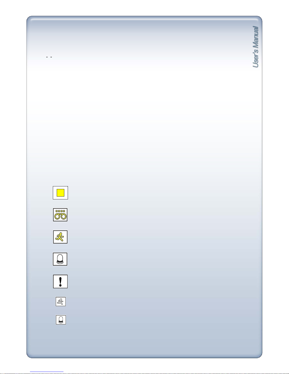
4-2. Display Status
[Continuous Recording]
[Stop Recording]
[Alarm Recording]
[Motion Recording]
[Motion detected]
[Panic Recording]
[Alarm-In detected]
17
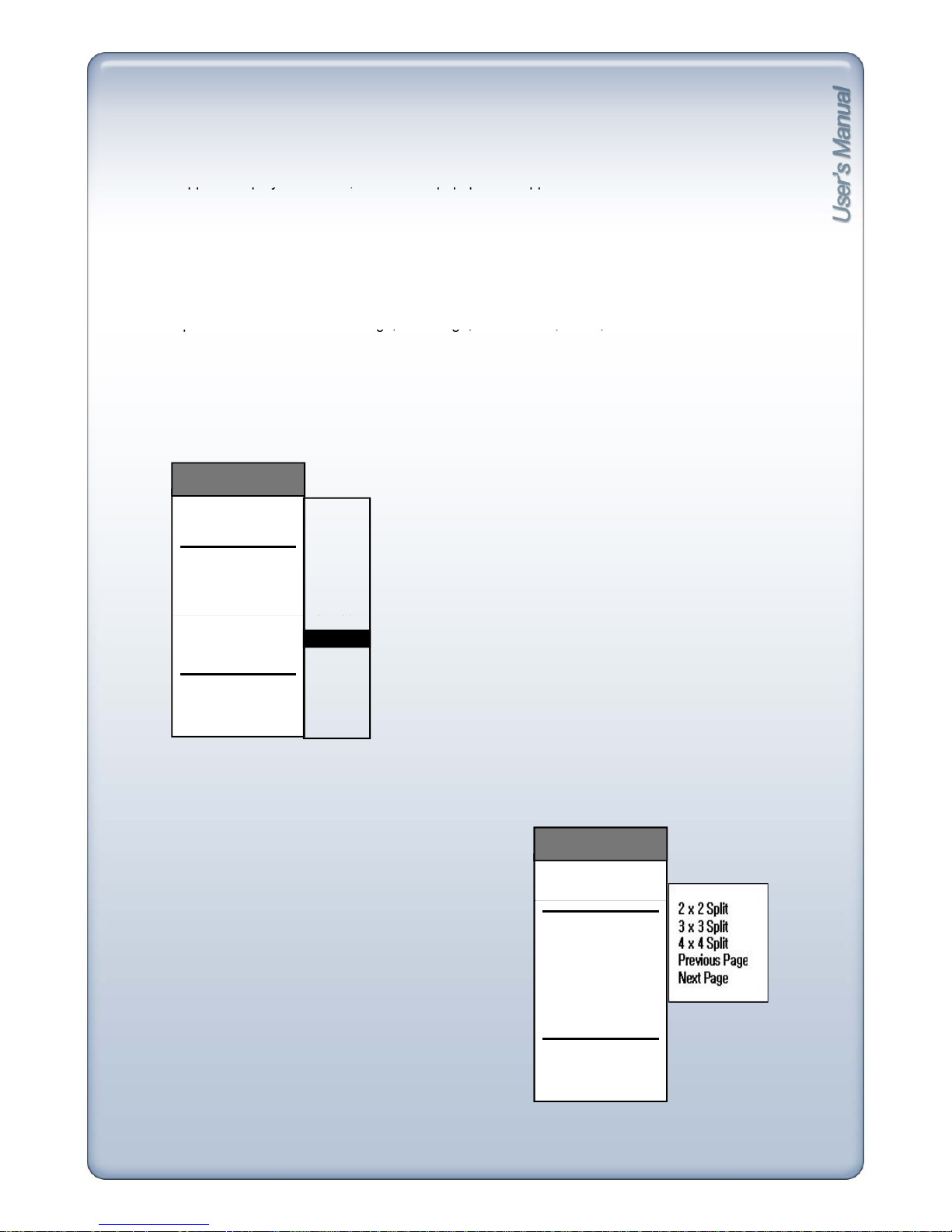
4-3. Popup Menu
By clicking right button of mouse, Monitoring popup menu appears in live mode, Playback popup
menu a
pp
ears in playback mode, PTZ control popup menu appears in PTZ mode.
While in LIVE display, click right button of mouse and MONITORING popup appears.
In full screen mode: All sub-menus are activated.
In split screen mode: PTZ, Zoom, PIP menus are not activated.
In 16 s
p
lit screen mode: Previous Page, Next Page, PTZ Control, Zoom, PIP are not activated.
pp p y , p p p pp
1) MONITORING POPUP MENU
1) Channel selection ( go to Channel ) sub-menu : CAM01 ~ CAM16
pg,g,,,
go to CHANNEL
SPLITTER
PTZ CONTROL
FREEZE
ZOOM
SEQUENCE
CAM01
CAM02
CAM03
CAM04
CAM05
CAM06
CAM07
CAM08
MONITORING
PIP
AUDIO
PANIC
PLAYBACK
SEARCH
SETUP MENU
C08
CAM09
CAM11
CAM12
CAM13
CAM14
CAM15
CAM16
CAM10
2) 2x2, 3x3, 4x4 Split
Displays in 4, 9, 16 Screen Division.
go to CHANNEL
SPLITTER
MONITORING
go to CHANNEL
SPLITTER
MONITORING
For 4ch/8ch DVR, 3X3 and 4X4 split sub-menus
will not be activated.
PTZ CONTROL
FREEZE
ZOOM
SEPUENCE
PIP
AUDIO
PANIC
PTZ CONTROL
FREEZE
ZOOM
SEQUENCE
PIP
AUDIO
PANIC
PLAYBAC
K
SEARCH
SETUP MENU
PLAYBAC
K
SEARCH
SETUP MENU
18
3) Previous Page
In full screen mode, clicking Previous Page menu will switch screen to lower number channel.
After channel 1, it rotates to channel 16.
In split screen mode, clicking Previous Page menu will switch screen to lower number
channel groups.
e.g.) [ch1/2/3/4] → [ch13/14/15/16] → [ch9/10/11/12] → [ch5/6/7/8]
In 16 split display mode, this function is not available.
4) Next P
age
In full screen mode, clicking Next Page menu will switch screen to higher number channel.
After channel 16, it rotates to channel 1.
In split screen mode, clicking Next Page menu will switch screen to higher number channel
groups.
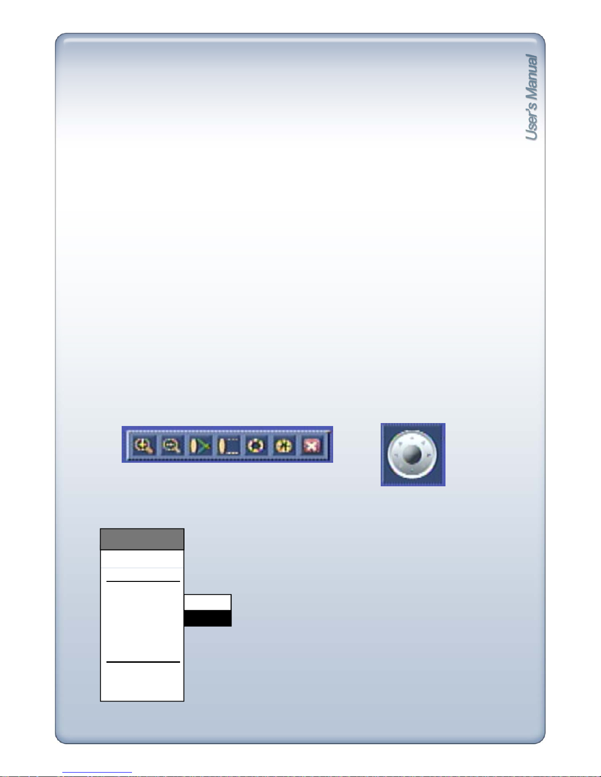
5) PTZ Control
PTZ Panel appears when PTZ Control menu is clicked.
Click buttons with mouse control, or press SEQUENCE button to shift keys.
e.g.) [ch1/2/3/4]
→
[ch5/6/7/8]
→
[ch9/10/11/12]
→
[ch13/14/15/16]
In 16 split display mode, this function is not available.
See Chapter 7 7-1 Live Monitoring 5] PTZ mode for more details.
6) Freeze : On / Off
[Virtual Joystick]
[PTZ Control Toolbar]
go to CHANNEL
MONITORING
In Full screen mode, FRZ icon appears and screen freezes.
In split screen mode, FRZ icon appears and all channels freeze.
To exit freeze mode, click any sub-menus from MONITORING
except Audio and Panic.
On
Off
SPLITTER
PTZ CONTROL
FREEZE
ZOOM
SEQUENCE
PIP
AUDIO
PANIC
PLAYBACK
SEARCH
SETUP MENU
19
11) Search
Only the Admin and Manager have authority to access this Menu.
It is to search recorded data easily and playback.
Search by Time/Date, Event list and Bookmark is available.
12) Setup Menu
Only the Admin and Manager have authority to access and change all settings on all Sub-Menus.
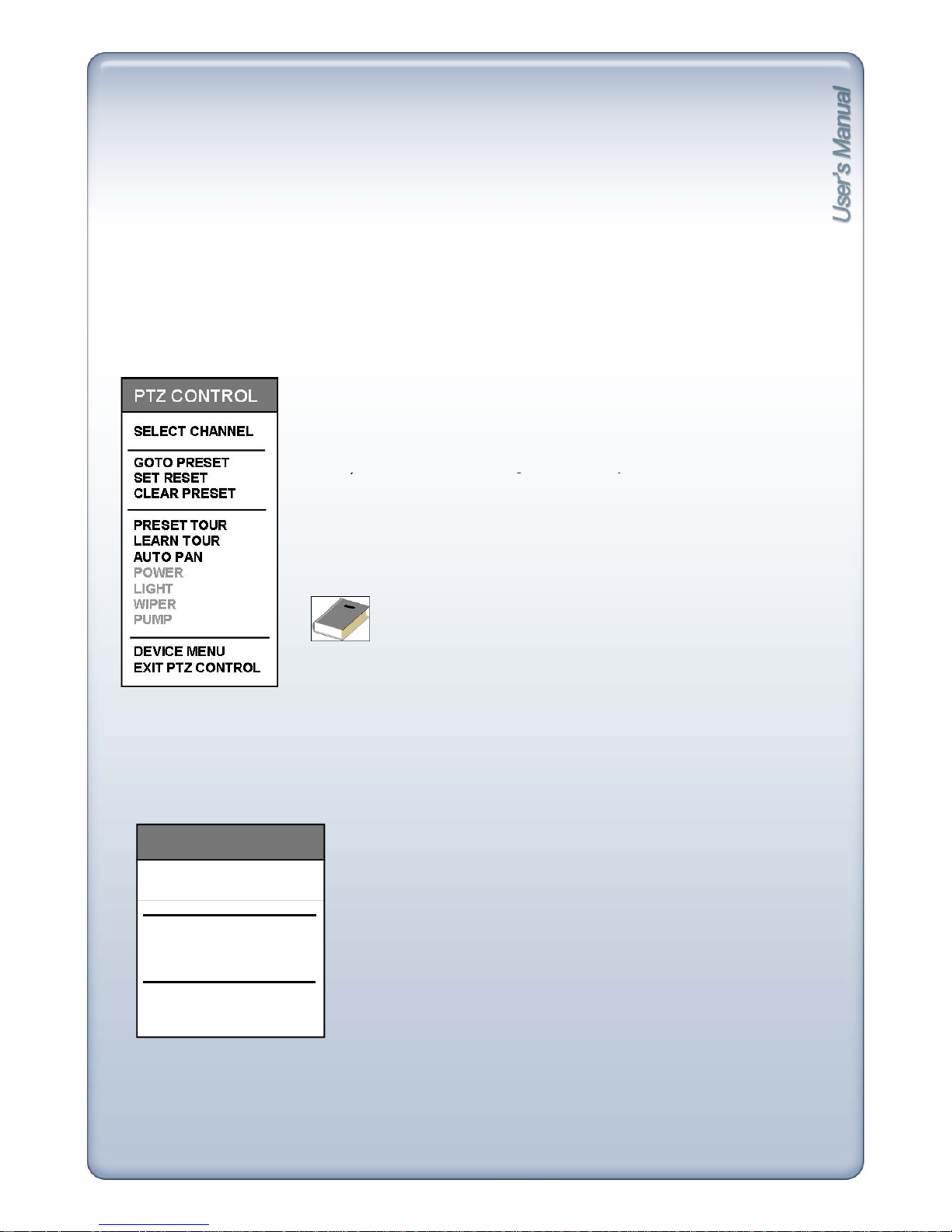
[2] PTZ CONTROL Popup
While in PTZ mode, click right button of mouse and PTZ popup appears.
1) Preset Tour : Pan/Tilt on preset directions.
2) Learn Tour : Repeat learned Pan/Tilt directions.
3
)
A
uto Pan : Pan left/right automatically.
)
gy
4) Power : On/Off
5) Light : Light on at night.
6) Wiper : Wipe moisture or water drops.
7) Pump : Pump water to remove dust.
8) Device Menu : Show OSD Menu of PTZ camera.
9) Exit PTZ Control : Exit and go back to Live view mode.
[3] PLAYBACK Popup
<Note>
Menus from 1) to 7) may not be available according to PTZ camera models.
1) Bookmark : Clicking BOOKMARK button while in playback mode,
time/date will be remembered for Bookmark Search.
While in Playback mode, click right button of mouse and Playback popup appears.
go to CHANNEL
PLAYBACK
2) De-interl
ace :
Click DE
-
INTERLACE butt
on w
hile i
n playback mode.
De-interlace is available via Interpolation.
3) Search : Clicking SEARCH button while in playback mode will stop
playback mode and go to search mode.
Other Menus are the same as the Menus in LIVE POPUP.
SPLITTER
AUDIO
BOOKMARK
DE-INTERLACE
SEARCH
EXIT PLAYBACK
20
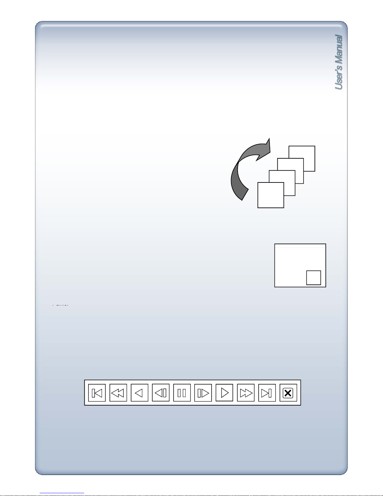
7) Zoom : On / Off
In full screen mode, Zoom icon activates and Live screen zooms in x2. Move selected frame
by mouse control or arrow keys.
8) Sequence : On / Off
In split screen mode, select channel button to activate zoom
icon and
live screen zooms in x2
.
To exit zoom mode, click any sub-menus from MONITORING except Audio and Panic.
CH2
CH3
CH4
.
.
.
While in full screen mode, clicking ON for sequence will
cause the connected camera’s channel to display
sequentially according to the preset dwell-time. Access
[MENU]-[Devices]-[Display]-[Main Monitor]-Sequence
Interval Popup for dwell-time setup and Sequence Mode
Popup to set number of channels to sequence.
-
CH1
9) PIP : On / Off
To exit Sequence mode, click any sub
menus from
MONITORING except Audio and Panic.
While in Li
ve mode, one channel displays in full screen mode w
hil
e another
small screen displays in insert window.
Small screen displays in sequence according to preset interval.
([Menu]-[Device]-[Display]-[Main]-[PIP Duration])
To exit PIP mode, click any sub-menus from MONITORING except Audio and
CAM-01
2
Panic.
10) Playback
Press Playback from MONITORING popup menu or search menu and play panel appears as
below and begin playback of recorded data on HDD. Freeze, Slow/Fast (backward) playback
[Playback Control Toolbar]
control is available with play panel
.
21
1 2 3 4 5 6 7 8
9
10
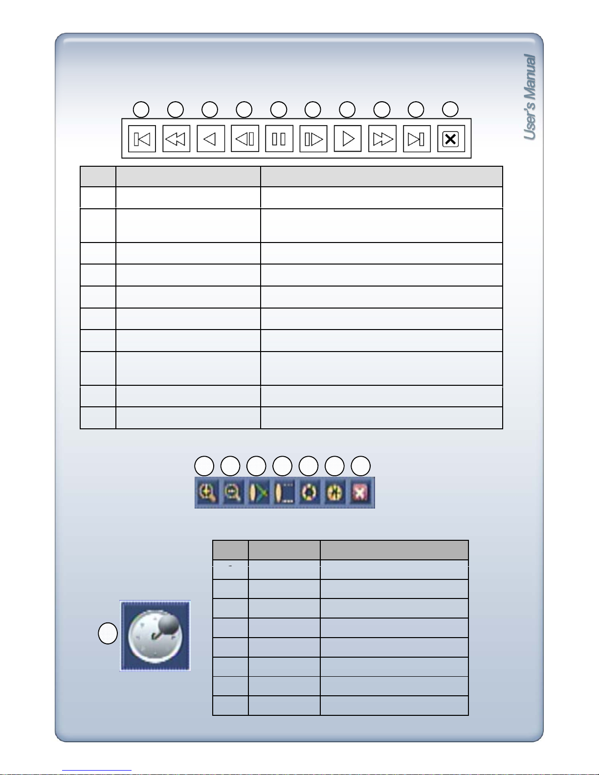
4-4. Toolbar
[1] PLAYBACK Toolbar
No. Button Function
1 Go to the first image Move to the beginning of playback
2 Decrease speed Playback speed decreases in forward playback
(Playback speed increases in backward playback)
3 Backward playback Playback in reverse direction
4 Previous image Shows previous image in freeze mode
5
Freeze
Freeze playback
6 Next image Shows next image in freeze mode
7 Forward Playback Playback in forward direction
8 Increase speed Playback speed increases in forward playback
(Playback speed decreases in backward playback)
[2] PTZ Toolbar
9 Go to the last image Move to the end of playback
10 Exit Exit playback mode and return to live mode
1 2 3 4 5 6 7
[PTZ Control Toolbar]
No. Button Function
8
1
TELE
Z
oom in
2 WIDE Zoom out
3 NEAR Focus near
4 FAR Focus far
5 OPEN Iris open
[Virtual Joystick]
6 CLOSE Iris close
7 EXIT Exit PTZ toolbar
8 JOYSTICK Camera Pan/Tilt operation
22
CHAPTER 5. DVR SETUP
5-1. Operation
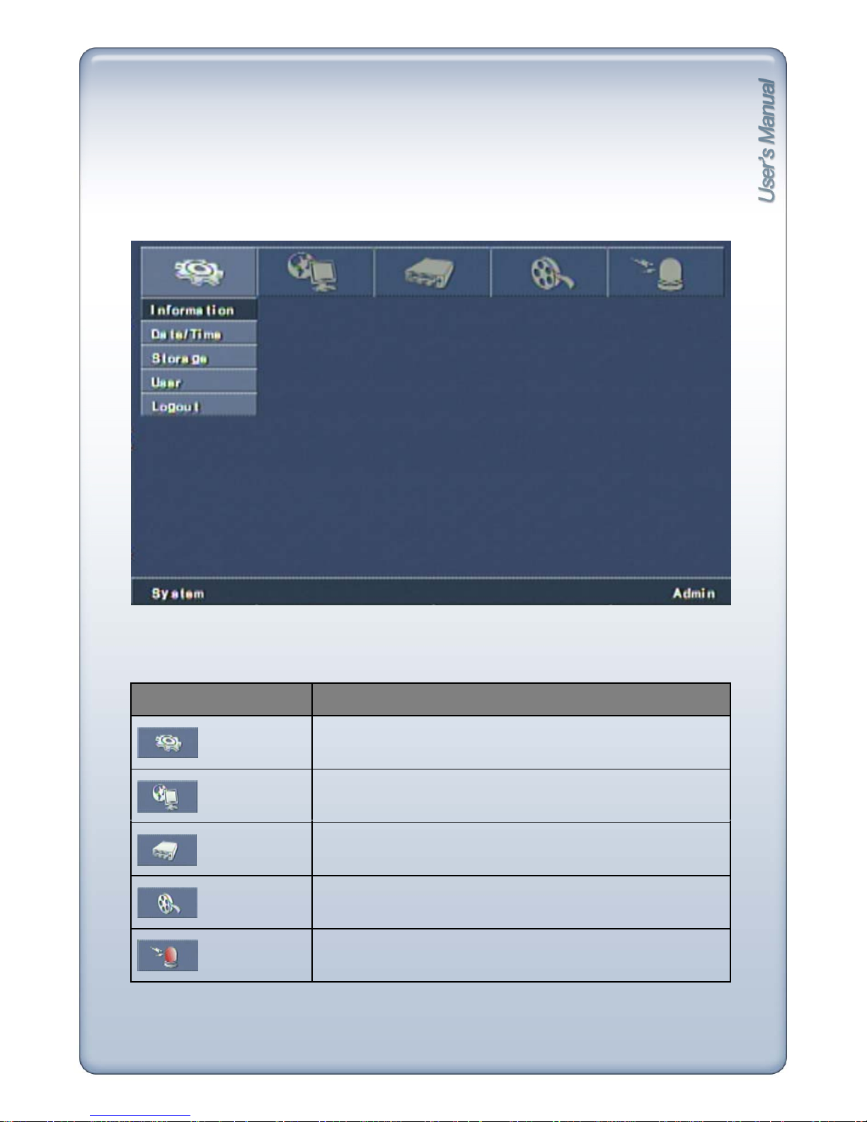
1) Main Menu
Setup Group Details
System Information, Date/Time, Storage, User, Logout
Network LAN, Notification
Devices Display, Camera, Audio, Remote Control
Record Setup, Schedule, Pre-event, Backup
Event
A
larm, Motion, Video Loss, Alarm-out, Buzze
r
23
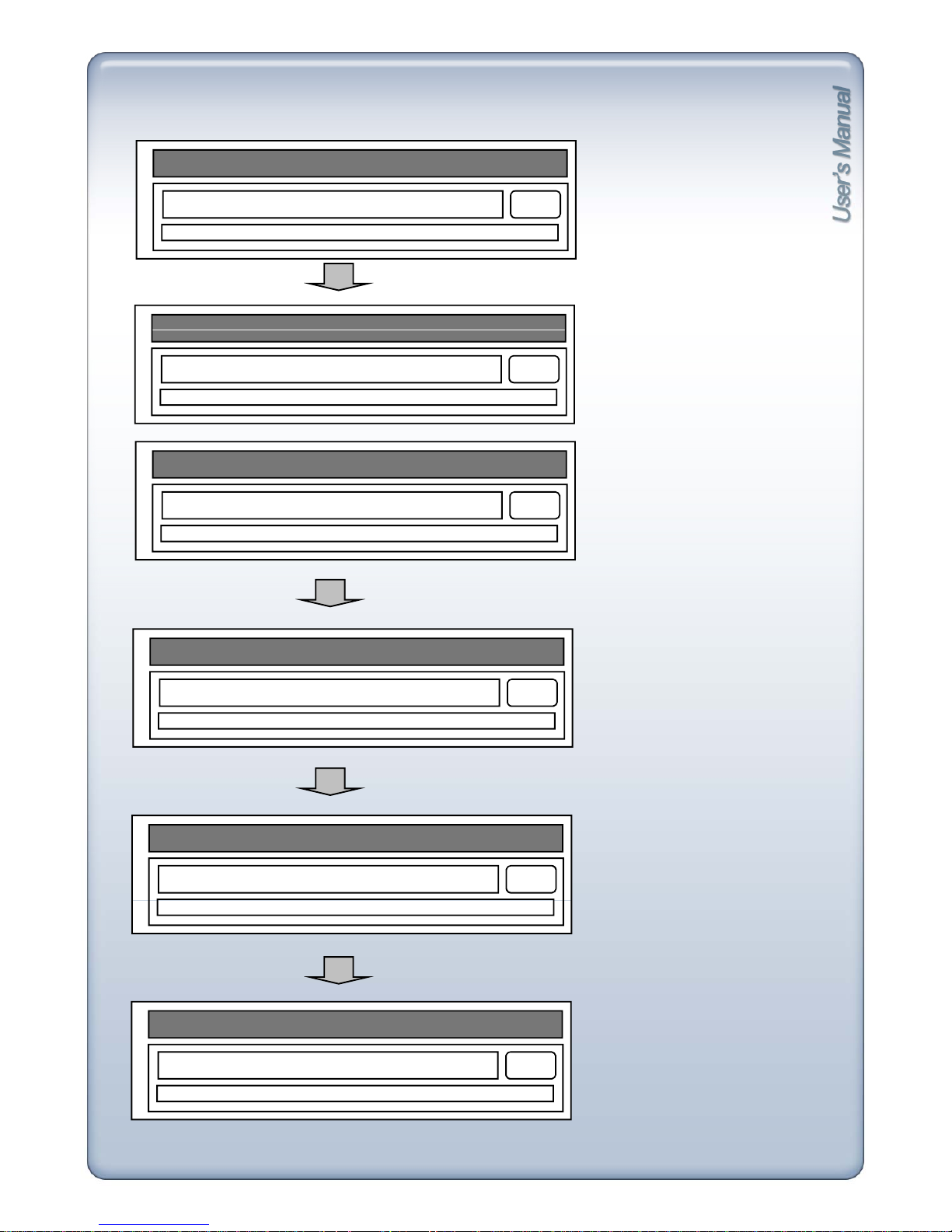
[2] Initialization
INITIALIZE DVR SYSTEM…
When powered on, messages
displays in order.
BOARD/PERI DEVICE..
HDD2
System will check for connected
HDDs. If no HDD is connected,
it will move to the next message.
To skip checking HDD, click
SKIP button or press [MENU]
button.
INITIALIZE DVR SYSTEM
…
CHECK INTERNAL HDD1..
SKIP
INITIALIZE DVR SYSTEM…
CHECK INTERNAL HDD2..
SKIP
INITIALIZE DVR SYSTEM…
SKIP HDD DETECTION
HDD2
INITIALIZE DVR SYSTEM…
DISPLAY OSD/ICON
OK
INITIALIZE DVR SYSTEM…
Once initialization is completed,
live screen displays.
COMPLETE DVR SYSTEM INITIALIZATION
24
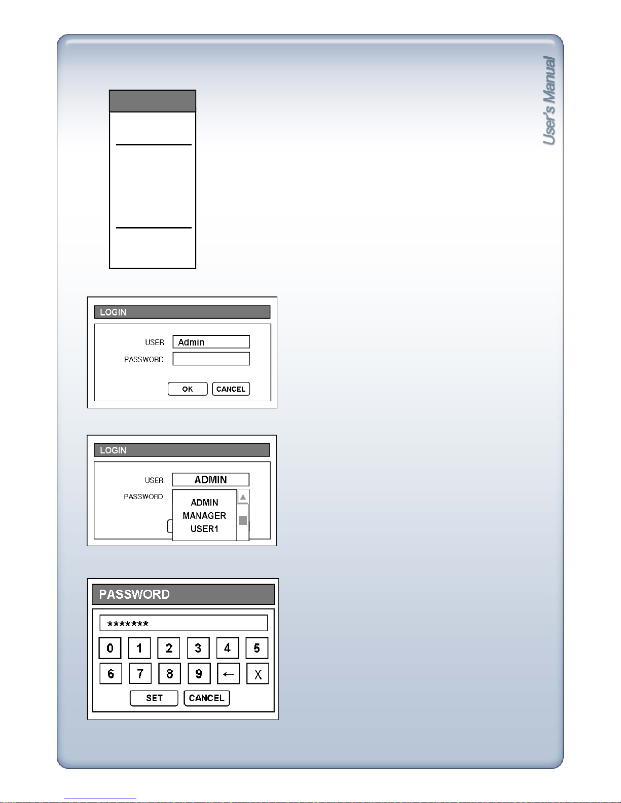
[3] System Login
MONITORING
1) Press right button of mouse or press [MENU] button and
MONITORING screen appears.
go to
CHANNEL
SPLITTER
PTZ CONTROL
FREEZE
ZOOM
SEQUENCE
PIP
AUDIO
PANIC
PLAYBACK
SEARCH
SETUP MENU
2) Click Setup Menu and Login window appears.
3) Click User and you can select user grade from the
scroll box.
4) Input 1 to 8 digit number password of the selected
user grade
← : Backspace
X : Clear all
Default Password :
Admi
n : blank
(NUL)
Manager : 1
User 1~User 8 : 2 ~ 9
25
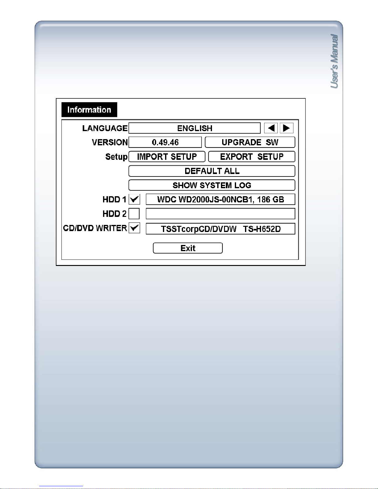
5-2. System
[1] Information
- Language : Select language of System Menu among English, French, Spanish, Italian, Portuguese,
Dutch, Russian, German, Turkish and Polish.
-
Version
: Current firmware version
.
- Upgrade SW : Update current firmware.
- Import Setup : Bring setup values saved from USB storage.
You can apply same setup value of a DVR to other DVRs easily.
- Export Setup : Save current setup value to USB storage.
- Default All : Factory default for all menus. (See chapter10 for factory default values)
If you run Default All, Time/Date and Password will all be defaulted.
After Default All, set time/date and clear HDD for normal operation.
- Show System Log : Show list of Start/End time of Panic Recording, Start/End time of Schedule
recording and WHO/WHEN logged in.
- HDD1, HDD2 : Display Manufacturer/Size of HDD.
- CD WRITER : Display Manufacturer of CD-RW.
- HDD1, HDD2, CD/DVD Writer Checkbox : Check checkbox to request information of connected
device. If checkbox is not checked, it skips detection to reduce booting time.
26
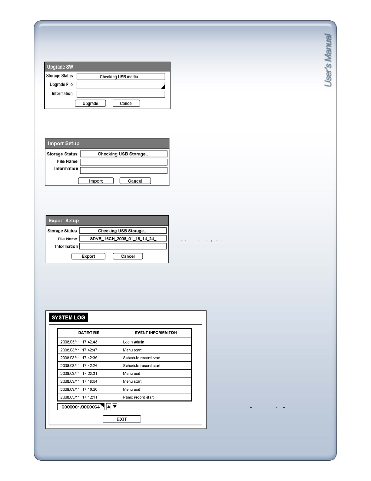
Click Upgrade SW button and pop-up box appears.
- Storage Status : Shows firmware update progress.
(See chapter 11 for warning and error messages).
- Upgrade File : Name of file to upgrade.
-Information : Shows error code in case of error.
Recording will stop while upgrading.
Click Import Setup button and import window appears.
-File Name : Shows the name of the file in USB memory
stick which contains setup value.
- Information : Shows error code in case of error.
Click Export Setup button to save DVR’s setup value to
USB memory stick.
- Export : Save export setup value to USB memory stick.
Shows list of Start/End time of Panic Recording, Start/End time of Schedule
recordin
g
and WHO/WHEN logged in/out.
- Date/Time : Date and time of event.
- Event Information : Event type (Panic
record start/stop, Schedule record
g
gg
start/stop,
HDD full
record stop, etc
)
See chapter 11 for more details.
- Page box : Current page / Total pages
(maximum 2,048 pages).
You can type in page number directly.
- Up button : go to previous page.
- Down button :
g
o to next page.
g
pg
27
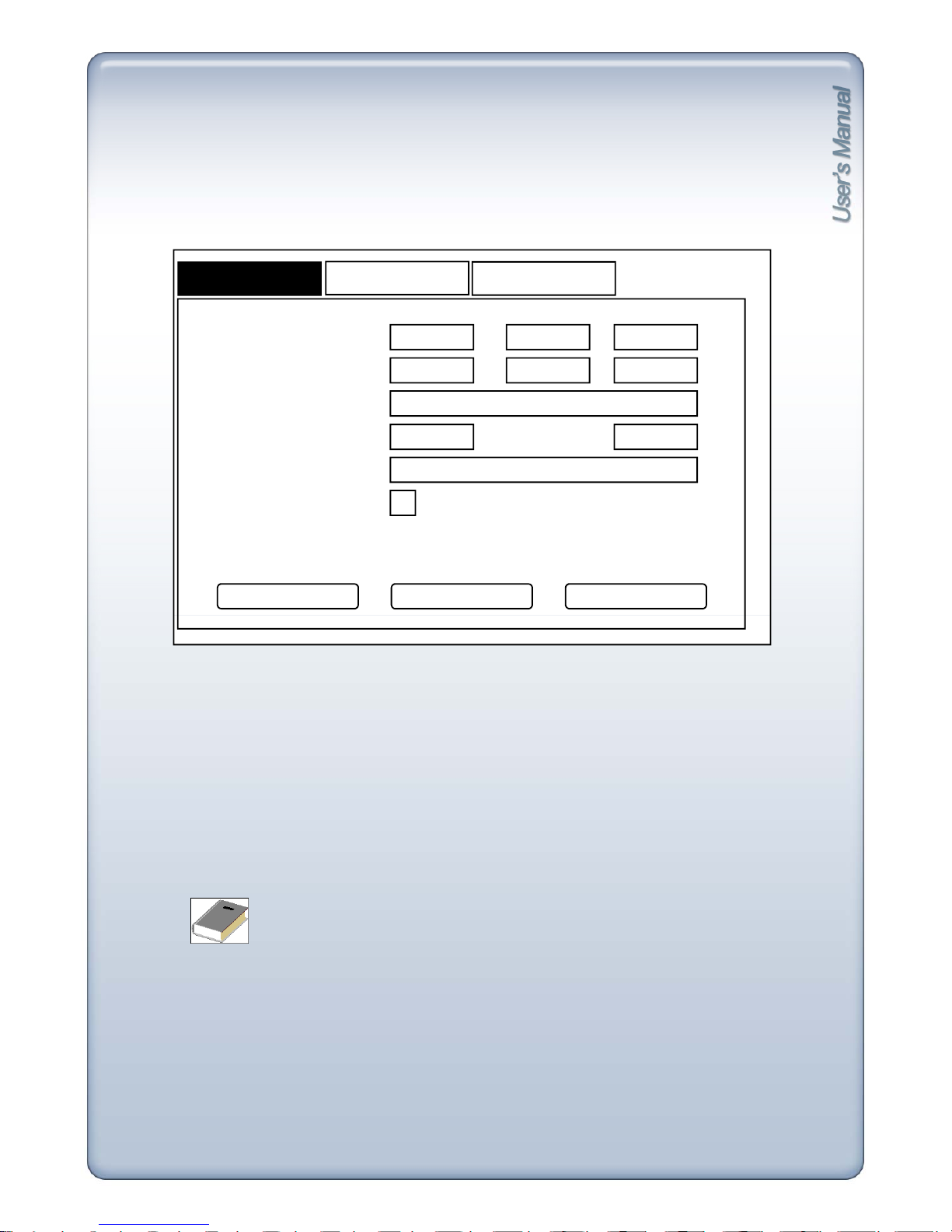
[2] Date / Time
1) Date / Time
Set Date/Time of system.
DATE/TIME
HOLIDAY
TIME SYNC
DATE 2007
TIME
DATE FORMAT
TIME FORMAT
12 10
19 22 18
2007/12/10
MONTH FORMAT 12 19
USE DST
(
GMT+00:00
) UK (GMT)
TIME ZONE
SAVE DEFAULT CANCEL
- Date : Set Year, Month, Day. Year can be set from 2008 to 2099.
- Time : Set Hour, Minute, Second.
- Date Format : Choose date format among YY/MM/DD, MM/DD/YY and DD/MM/YY.
- Month Format : Choose month format between numbers and letters.
- Time Format : Choose 12-hour mode (am./pm.) or 24-hour-mode.
- Time Zone : Select area zone and input current time.
(GMT+09:00) Seoul Æ GMT standard time + 09:00 = Time of Seoul, Korea.
- Use DST checkbox : Check box for Daylight Saving Time (Summer Time).
- Time cannot be defaulted.
- Do not set time earlier than the time of the last recorded data.
- On initial setup, after default all, be sure to format HDD after setting up time/date.
<Note>
28
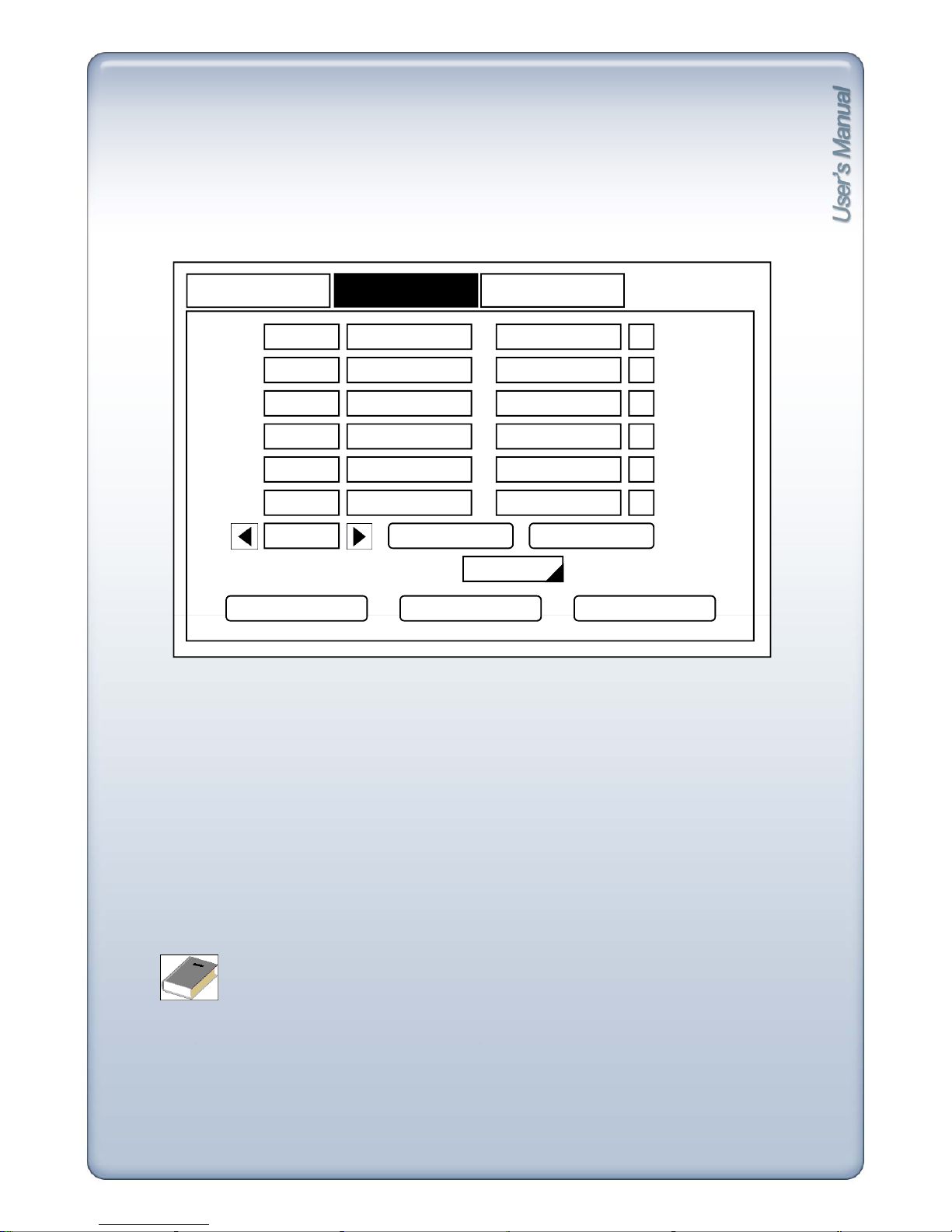
2) Holiday
Set
national ho
lid
ays or ho
lid
ays on calendar to record as se
tti
ng for Sunday in Schedule Record
Setup.
DATE/TIME
HOLIDAY
TIME SYNC
MONTH DAYNo.
001
002
003
SAVE DEFAULT CANCEL
004
005
01/01 ADD DELETE
SELECT DAY OF WEEK SUNDAY
- Add : Click add button and today’s month and day will be added on the screen.
Click month and da
y
to change the date of the holiday.
yg y
- Delete : Delete list, checkbox of which is marked.
- Select day of week: Set selected day of week as holiday. (Default is Sunday)
- No/No: Current Page/Total Pages
- Left arrow button : Previous page.
- Right arrow button : Next page.
- Checkbox : Check box of the date to delete. Press Delete button to delete selected date.
- Up to 100 days can be set as holiday.
- Holida
y
s that do not fall on the same date each year should be updated once the current
<Note>
yyp
year’s holiday has passed.
29
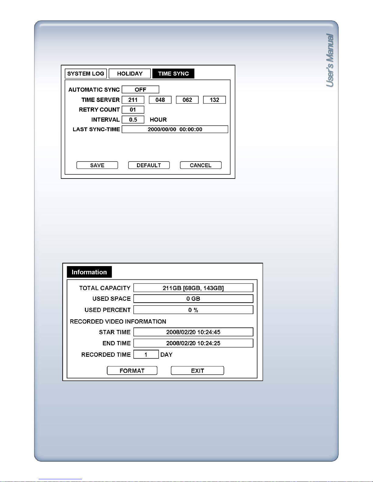
3) Time Sync
-
Automatic Sync
: Choose between On/Off
.
- Time Server : Input sync server IP address (SNTP).
- Retry Count : Select from 1 to 30 retries.
- Interval : Automatic Sync Interval (0.5, 1, 2, 3, 4, 5, 6, 12, 24 hours)
- Last Sync-Time : Shows time of Last Sync.
[3] Storage
Shows HDD total capacity, start time/end time of recorded data and can format HDD.
- Total Capacity : Shows total size of HDD [size of HDD1, size of HDD2]
- Used Space : Shows total size of recorded image data.
- Used Percent : Shows the percentage of recorded image data.
- Start Time : Shows start time of recorded data on HDD.
- End Time : Shows end time of recorded data on HDD.
- Recorded Time : Total number of days from Start Time till End Time.
- Format : Format HDD.
30
 Loading...