


Xeno XDR5K4 real time DVRs
SET UP AND USER MANUAL

Xeno XDR5 DVR manual V1.0
BEFORE YOU BEGIN
Read these instructions before installing or operating this product.
Note: This installation should be made by a qualified service person and should conform to local codes.
This manual provides installation and operation information. To use this document, you must have the
following minimum qualifications:
-voltage electrical connections
INTENDED USE
Only use this product for its designated purpose; refer to the product specification and user documentation.
CUSTOMER SUPPORT
For assistance in installing, operating, maintaining and troubleshooting this product refer to this document
and any other documentation provided. If you still have questions, please contact Norbain Technical
Support and Sales:
Norbain Ltd
210 Wharfedale Road, IQ Winnersh, Wokingham, Berkshire RG41 5TP
+44 118 912 5000
Note: You should be at the equipment and ready with details before calling Technical Support.
CONVENTIONS USED IN THIS MANUAL
Boldface or button icons highlight command entries. The following WARNING, CAUTION and Note
statements identify potential hazards that can occur if the equipment is not handled properly:
WARNING:
Improper use of this equipment can cause severe bodily injury or equipment damage.
** CAUTION:
Improper use of this equipment can cause equipment damage.
Note: Notes contain important information about a product or procedure.
3

The crossed-out wheeled bin mark symbolizes that within the European Union the product
must be collected separately at the product end-of-life. This applies to your product and any
peripherals marked with this symbol. Do not dispose of these products as unsorted municipal
waste.
CE MARK
This apparatus is manufactured to comply with the radio interference. A Declaration of
Conformity in accordance with the following EU standards has been made. The manufacturer
declares that the product supplied with this document is compliant the provisions of the EMC
CE RoHS2: 2011/65/EU
* This symbol indicates electrical warnings and cautions.
** This symbol indicates general warnings and cautions.
NORBAIN SD LTD reserves the right to make changes to the product and specification of the product from
time to time without prior notice.
WARNINGS AND CAUTIONS
To reduce the risk of fire or electric shock, do not insert any metallic objects through the ventilation grills or
other openings on the equipment.
IMPORTANT SAFEGUARDS
1. READ AND RETAIN INSTRUCTIONS
Read the instruction manual before operating the equipment.
4

Retain the manual for future reference.
2. CLEANING
Turn the unit off and unplug from the power socket before cleaning. Use a damp cloth for cleaning. Do not
use harsh cleansers or aerosol cleaners.
3. ATTACHMENTS
Do not use attachments unless recommended by manufactured as they may affect the functionality of the
unit and result in the risk of fire, electric shock or injury.
4. MOISTURE
Do not use equipment near water or other liquids.
5. ACCESSORIES
Equipment should be installed in a safe, stable location. Any wall or shelf mounting accessory equipment
should be installed using the manufacturer’s Instructions. Care should be used when moving heavy
equipment. Quick stops, excessive force, and uneven surfaces may cause the equipment to fall causing
serious injury to persons and objects.
6. VENTILATION
Openings in the equipment, if any, are provided for ventilation to ensure reliable operation of the unit and to
protect if from overheating. These openings must not be blocked or covered
7. POWER SOURCES
The equipment should be operated only from the type of power source indicated on the marking label. If you
are not sure of the type of power supplied at the installation location, contact your dealer. For equipment
designed to operate from battery power, refer to the operating instructions.
8. GROUNDING OR POLARIZATION
If the equipment is powered through a three-way grounding-type plug, a plug having a third (grounding) pin,
the plug will only fit into a grounding-type power outlet. This is a safety feature. Do not defeat the safety
purpose of the grounding-type plug.
If your outlet does not have the grounding plug receptacle, contact your local electrician.
9. CORD AND CABLE PROTECTION
Route power cords and cables in such a manner to protect them from damage by being walked on or
pinched by items places upon or against them.
10. LIGHTNING
For protection of the equipment during a lightning storm or when it is left unattended and unused for long
periods of time, unplug the unit from the wall outlet. Disconnect any antennas or cable systems that may be
connected to the equipment.
This will prevent damage to the equipment due to Lightning or power-line surges.
11. OVERLOADING
Do not overload wall outlets and extension cords as this can result in a risk of fire or electric shock
12. SERVICING
Do not attempt to service the equipment yourself as opening or removing covers may expose you to
5

dangerous voltage or other hazards. Refer all servicing to qualified service personnel.
13. DAMAGE REQUIRING SERVICE
Unplug the equipment from the wall outlet and refer servicing to qualified service personnel under the
Following conditions:
A. When the power supply cord or the plug has been damaged.
B. If liquid has spilled or objects have fallen into the Unit.
C. If the equipment has been exposed to water or other liquids.
D. If the equipment does not operate normally by following the operating instructions, adjust those controls
that are covered by the operating instructions as Improper adjustment for other controls may result in
damage to the unit.
E. If the equipment has been dropped or the casing is damaged.
F. When the equipment exhibits a distinct change in performance.
14. REPLACEMENT PARTS
When replacement parts are required, be sure the service technician uses replacement parts specified by
the manufacturer or that have the same characteristics as the original part. Unauthorized substitutions may
result in fire, electric shock, or other hazards.
15. SAFETY CHECK
Upon completion of any service or repairs to the equipment, ask the service technician to perform safety
checks to verify that the equipment is in proper operating condition.
16. FIELD INST
The installation of equipment should be made by a qualified service person and should conform to
all local codes.
17. CAUTION - THESE SERVICING
INSTRUCTIONS ARE FOR USE BY QUALIFIED SERVICE PERSONNEL ONLY.
TO REDUCE THE RISK OF ELECTRIC SHOCK DO NOT PERFORM ANY SERVICING OTHER THAN
THAT CONTAINED IN THE OPERATING INSTRUCTIONS UNLESS YOU ARE QUALIFIED TO DO SO
18. Use
certified/Listed
ALLA
TION
Class 2 power source
only
.
6

WARNING
This is a Class A product. In a domestic environment this product may cause radio interference in which
case the user may be required to take adequate measures.
CE COMPLIANCE STATEMENT
7

Product Key Features
Compression
PAL/NTSC adaptive video inputs.
H.264 video compression with high reliability and superior definition.
Real time 25ips per channel at WD1.
Each channel supports dual-stream. Main stream and Event streams.
Independent configuration for each channel, including resolution, frame rate, bit rate, image quality, etc.
Input and output video quality is configurable.
Encoding for both audio/video composite stream and video stream; audio and video synchronizing output
during composite stream encoding.
Watermark technology.
Local Monitoring
Simultaneous HDMI/VGA and CVBS outputs;
HDMI output and VGA output at up to 1920×1080P resolution.
1/4/6/8/9/16-multi screen viewing options.
Sequences of single cameras or split screens can be shown with programmable dwell times.
Quick set menu is provided for live view.
Camera viewing access is controlled via users rights
Motion detection, tamper-proof, video exception alert and video loss alert functions.
Privacy mask.
Multiple PTZ protocols supported; PTZ presets and tours
HDD Management
Supports 1 SATA hard disk internally, max 4TB per drive.
8 network disks (8 NAS disks, or 7 NAS disks+1 IP SAN disk) can be connected.
HDD group management.
Support HDD standby function.
HDD property: redundancy, read-only, read/write (R/W).
HDD quota management; different capacity can be assigned to different channel.
Recording, Capture and Playback
Up to 4-ch of synchronous playback at WD1 real time.
Normal and event video encoding parameters.
Multiple recording trigger types: normal, motion.
8 recording time periods with separated recording types.
Pre-record and post-record for motion detection for recording, and pre-record time for schedule.
Searching record files by events.
Customization of bookmarks, searching and playing back by bookmarks.
8

Locking and unlocking record files.
Local redundant recording.
Searching and playing back record files by channel number, recording type, start time, end time, etc.
Motion analysis for the selected area in the video.
Digital zoom available in play back mode
Supports pause, play fast, play slow, skip forward, and skip backward when playback, mouse controlled
timeline selection
Holiday recording schedule configuration.
Overwrite and non-cycle recording mode.
Archive
Export video data by USB, or SATA storage device
Export video clips when playback.
Management and maintenance of backup devices.
Alarm and Exception
Alarm for video loss, motion detection, tampering, audio, abnormal signal, video input/output standard
mismatch, illegal login, network disconnected, IP confliction, abnormal record/capture, HDD error, and HDD
full, etc.
Alarm triggers full screen monitoring, audio alarm, notifying client host, sending email and relay output.
Automatic restore when system is abnormal
Other Local Functions
Operation via front panel, mouse, IR remote control
Three-level user management; admin user is allowed to create many operating accounts and define their
operating permissions, which includes the limit to access any channel.
Operation, alarm, exceptions and log recording and searching.
Import and export of device configuration information.
Network Functions
1 self-adaptive 10M/100M NIC card is available.
IPv6 is supported.
TCP/IP protocol, PPPoE, DHCP, DNS, DDNS, RTSP, NTP, SADP, SMTP, SNMP, UPnP™, NFS, and
iSCSI are supported.
TCP, UDP and RTP for unicast.
Remote search, playback, download, locking and unlocking the record files, and downloading files broken
transfer resume.
Remote parameters setup; remote import/export of device parameters.
Remote viewing of the device status, system logs and alarm status.
Remote HDD formatting and program upgrading.
9

Remote system restart and restore default settings.
RS-485 transparent channel transmission.
Alarm and exception information can be sent to the remote host
Remotely enable/disable recording.
Remote PTZ control.
Two-way audio
Embedded WEB server.
Development Scalability:
SDK for Windows and Linux system.
Source code of application software for demo.
Development support and training for application system.
10

Table of Contents
Product Key Features .................................................................................................................... 8
C H A P T E R 1 ......................................................................................................................... 16
Installation ................................................................................................................................... 16
1.1 Before your start ............................................................................................................. 17
DVR Pre-Installation ...................................................................................................... 17
DVR Installation............................................................................................................. 17
1.2 Hard Disk Installation ...................................................................................................... 18
1.3 Telemetry connections.................................................................................................... 20
PTZ RS-485 Connections .............................................................................................. 20
1.4 HDD Storage Calculation Chart ...................................................................................... 20
1.5 Menu Structure ............................................................................................................... 22
C H A P T E R 2 ......................................................................................................................... 23
Introduction ................................................................................................................................. 23
2.1 Front Panel ..................................................................................................................... 24
2.2 USB Mouse Operation .................................................................................................... 25
2.3 Input Method Description ................................................................................................ 26
2.4 Rear Panel ..................................................................................................................... 27
C H A P T E R 3 ......................................................................................................................... 30
Getting Started ............................................................................................................................ 30
3.1 Using the Wizard for Basic Configuration ....................................................................... 31
C H A P T E R 4 ......................................................................................................................... 35
Live View ..................................................................................................................................... 35
4.1 Introduction of Live View ................................................................................................. 36
4.2 Operations in Live View Mode ........................................................................................ 37
4.2.1 Using the Mouse in Live View ............................................................................... 37
4.2.2 Using an Auxiliary Monitor .................................................................................... 38
4.2.3 Quick Setting Toolbar in Live View Mode ............................................................. 38
4.3 Adjust Camera Settings .................................................................................................. 41
4.3.1 Configuring Video Parameters .............................................................................. 41
4.3.2 Configuring Privacy Mask ..................................................................................... 41
4.3.3 Configuring OSD Settings ..................................................................................... 43
11

4.4 Adjusting Live View Settings ........................................................................................... 45
C H A P T E R 5 ......................................................................................................................... 47
PTZ Controls ............................................................................................................................... 47
5.1 Configuring PTZ Settings ................................................................................................ 47
5.2 Setting Presets, Tours & Learns ..................................................................................... 48
5.2.1 Customizing Presets ............................................................................................. 48
5.2.2 Calling Presets ..................................................................................................... 49
5.2.3 Customizing Tours ................................................................................................ 50
5.2.4 Calling Tours ........................................................................................................ 51
5.2.5 Customizing Learns .............................................................................................. 52
5.2.6 Calling Learns ...................................................................................................... 53
5.3 PTZ Control Toolbar ....................................................................................................... 55
C H A P T E R 6 ......................................................................................................................... 56
Record Settings ........................................................................................................................... 56
6.1 Configuring Encoding Parameters .................................................................................. 57
6.2 Configuring Record Schedule ......................................................................................... 60
6.3 Configuring Holiday Record ............................................................................................ 63
6.4 Configuring Motion Detection Record ............................................................................. 65
6.5 Configuring Redundant Record ...................................................................................... 70
6.6 Configuring HDD Group for Recording ........................................................................... 72
6.7 File Protection ................................................................................................................ 73
C H A P T E R 7 ......................................................................................................................... 76
Playback ...................................................................................................................................... 76
7.1 Playing Back Recorded Video ........................................................................................ 77
7.1.1 Playing Back by Channel ...................................................................................... 77
7.1.2 Playing Back by Time ........................................................................................... 81
7.1.3 Playing Back by Normal Video Search ................................................................. 83
7.1.4 Playing Back by Event Search .............................................................................. 86
7.1.5 Playing Back by Bookmark ................................................................................... 89
7.1.6 Playing Back by System Log ................................................................................ 93
7.2 Auxiliary Functions of Playback ...................................................................................... 96
7.2.1 Playing Back Frame by Frame.............................................................................. 96
12

7.2.2 Smart Search ....................................................................................................... 96
7.2.3 Digital Zoom ......................................................................................................... 99
C H A P T E R 8 ....................................................................................................................... 101
Archive ...................................................................................................................................... 101
8.1 Archiving Record Files .................................................................................................. 102
8.1.1 Quick Export ....................................................................................................... 102
8.1.2 Archiving by Normal Video Search ..................................................................... 103
8.1.3 Archiving by Event Search .................................................................................. 107
8.1.4 Archiving Video Clips .......................................................................................... 110
8.2 Managing Backup Devices ........................................................................................... 111
C H A P T E R 9 ....................................................................................................................... 116
Event Settings ........................................................................................................................... 116
9.1 Setting up Motion Detection .......................................................................................... 117
9.2 Detecting Video Loss .................................................................................................... 120
9.3 Detecting Camera Tampering ....................................................................................... 122
9.4 Handling Exceptions ..................................................................................................... 124
9.5 Setting Alarm Response Actions .................................................................................. 125
C H A P T E R 10 ..................................................................................................................... 126
Network Settings ....................................................................................................................... 126
10.1 Configuring General Settings ...................................................................................... 127
10.2 Configuring Advanced Settings ................................................................................... 128
10.2.1 Configuring DDNS ............................................................................................ 128
10.2.2 Configuring NTP Server .................................................................................... 131
10.2.3 Configuring Email ............................................................................................. 132
10.2.4 Configuring SNMP ............................................................................................ 134
10.2.5 Configuring PPPoE Settings ............................................................................. 135
10.2.6 Configuring UPnP™ ......................................................................................... 137
10.2.7 Configuring Remote Alarm Host ....................................................................... 138
10.2.8 Configuring Multicast ........................................................................................ 139
10.2.9 Configuring RTSP ............................................................................................. 140
13

10.2.10 Configuring Server and HTTP Ports ............................................................... 141
10.3 Checking Network Traffic ............................................................................................ 142
10.4 Configuring Network Detection ................................................................................... 143
10.4.1 Testing Network Delay and Packet Loss .......................................................... 143
10.4.2 Exporting Network Packet ................................................................................ 143
10.4.3 Checking Network Status ................................................................................. 144
10.4.4 Checking Network Statistics ............................................................................. 146
10.5 Single Stream Encoding ............................................................................................. 148
C H A P T E R 11 ..................................................................................................................... 149
System Configuration ................................................................................................................ 149
11.1 Basic Settings ............................................................................................................. 150
11.1.1 Configuring General Settings ............................................................................ 150
11.1.2 Configuring Advanced Settings ......................................................................... 151
11.1.3 Importing/Exporting Configuration Files ............................................................ 151
11.1.4 Restoring Default Settings ................................................................................ 153
11.1.5 Logging out/Shutting down/Rebooting Device .................................................. 154
11.2 Disk Management ....................................................................................................... 155
11.2.1 Initializing HDDs ............................................................................................... 155
11.2.2 Managing Network HDDs ................................................................................. 156
11.2.3 Managing HDD Group ...................................................................................... 158
11.2.4 Configuring Quota Mode ................................................................................... 161
11.2.5 Checking HDD Status ....................................................................................... 163
11.2.6 Checking S.M.A.R.T Information ...................................................................... 165
11.2.7 Configuring HDD Error Alarms .......................................................................... 165
11.2.8 Detecting Bad Sector ........................................................................................ 166
11.3 Managing User Accounts ............................................................................................ 168
11.3.1 Adding a User ................................................................................................... 168
11.3.2 Deleting a User ................................................................................................. 171
11.3.3 Editing a User ................................................................................................... 171
14

11.3.4 Changing Admin Password .............................................................................. 172
11.4 Firmware upgrading .................................................................................................... 174
11.4.1 Upgrading by Local Backup Device .................................................................. 174
11.4.2 Upgrading by FTP ............................................................................................ 174
11.5 Viewing System Information ....................................................................................... 176
11.5.1 Viewing Device Information .............................................................................. 176
11.5.2 Viewing Camera Information............................................................................. 176
11.5.3 Viewing Record Information .............................................................................. 177
11.5.4 Viewing Network Information ............................................................................ 177
11.5.5 Viewing HDD Information ................................................................................. 178
C H A P T E R 12 ..................................................................................................................... 180
Others ................................................................................................ ....................................... 180
12.1 Searching & Export Log Files ..................................................................................... 181
C H A P T E R 13 ..................................................................................................................... 184
Appendix ................................................................................................................................... 184
Glossary ................................ ................................................................ ............................. 185
FAQ .................................................................................................................................... 186
15

C H A P T E R 1
Installation
16

1.1 Before your start
DVR Pre-Installation
The XDR5K4 Series DVR is highly advanced surveillance equipment that should be carefully installed. Please take into
consideration the following precautionary steps before installation of the DVR.
1. Keep all liquids away from the DVR.
2. Install the DVR in a well-ventilated and dust-free area.
3. Ensure environmental conditions meet factory specifications.
4. Install a manufacturer recommended HDD.
DVR Installation
During the installation of the DVR:
1. Use brackets for rack mounting.
2. Ensure there is ample room for audio and video cables.
3. When installing cables, ensure that the bend radius of the cables are no less than five times than its diameter.
4. Connect both the alarm and RS-485 cable.
5. Allow at least 2cm (~0.75-inch) of space between racks mounted devices.
6. Ensure the DVR is grounded.
7. Environmental temperature should be within the range of -10 ºC ~ 55 ºC, 14ºF ~ 131ºF.
8. Environmental humidity should be within the range of 10% ~ 90%.
17
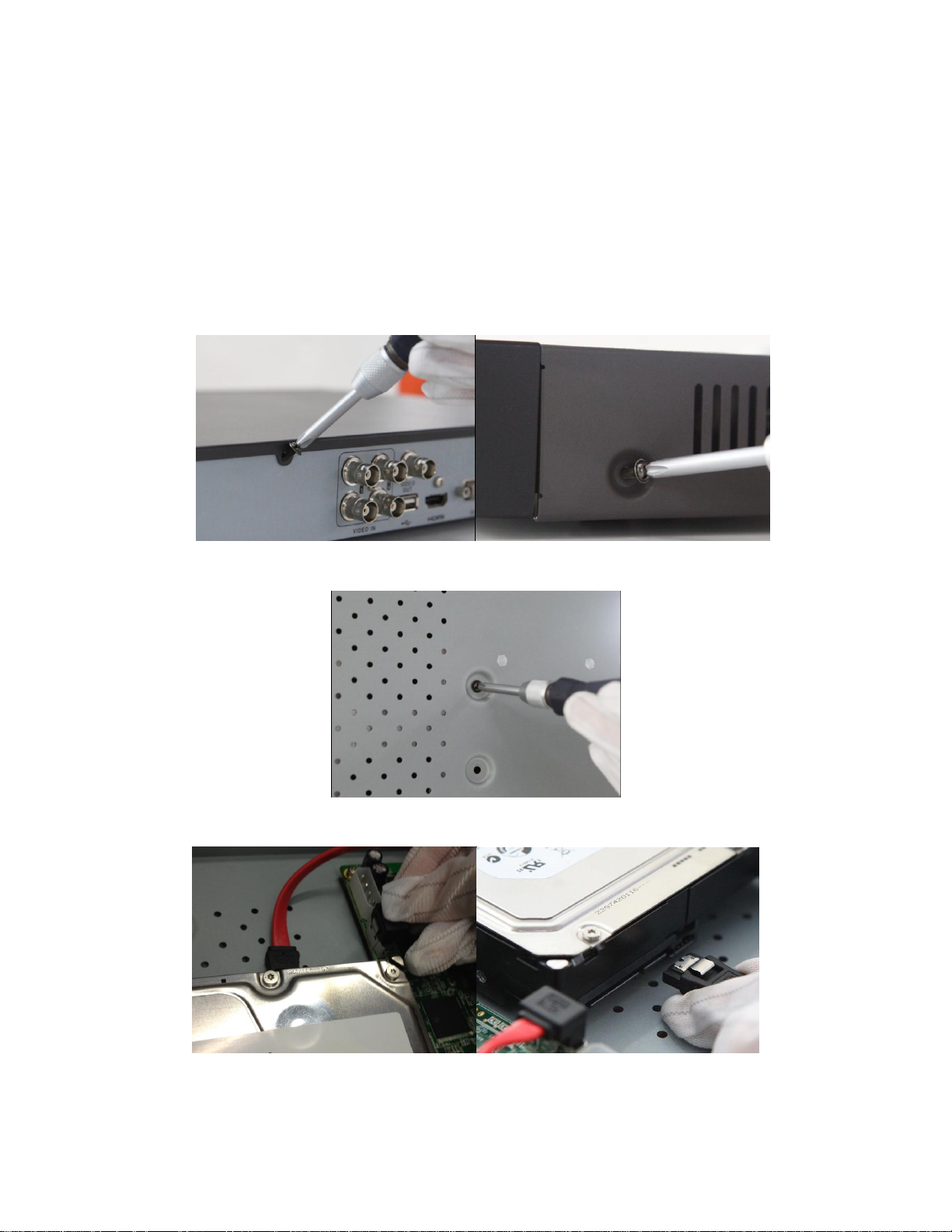
1.2 Hard Disk Installation
Before installing a hard disk drive (HDD), please make sure the power is disconnected from the DVR. A factory
recommended HDD should be used for this installation.
Tools Required: Screwdriver.
Steps:
1. Remove the cover from the DVR by unfastening the screws on the back and side.
2. Install the HDD in the HDD rack using the provided screws. Fasten the screws on the
button to fix the HDD.
3. Connect one end of the data cable to the motherboard of DVR and the other end to
the HDD.
18

4. Connect the power cable to the HDD.
5. Re-install the cover of the DVR and fasten screws.
19

Bit Rate
Storage Used
96K
42M
128K
56M
160K
70M
192K
84M
224K
98M
256K
112M
320K
140M
384K
168M
448K
196M
512K
225M
640K
281M
768K
337M
896K
393M
1024K
450M
1280K
562M
1.3 Telemetry connections
PTZ RS-485 Connections
To connect RS-485 devices to the DVR:
1. Press and hold the orange part of the pluggable block.
2. Insert signal cables into slots and release the orange part. Ensure signal cables are in tight.
Note: Make sure the pan/tilt receiver unit is connected to the D+ and D- of the RS-485 terminal of DVR.
1.4 HDD Storage Calculation Chart
The following chart shows an estimation of storage space used based on recording at one channel for an hour at a fixed
bit rate.
20

1536K
675M
1792K
787M
2048K
900M
Note: Please note that supplied values for storage space used is just for reference. Storage space used is estimated by
formulas and may have some deviation from actual value.
21
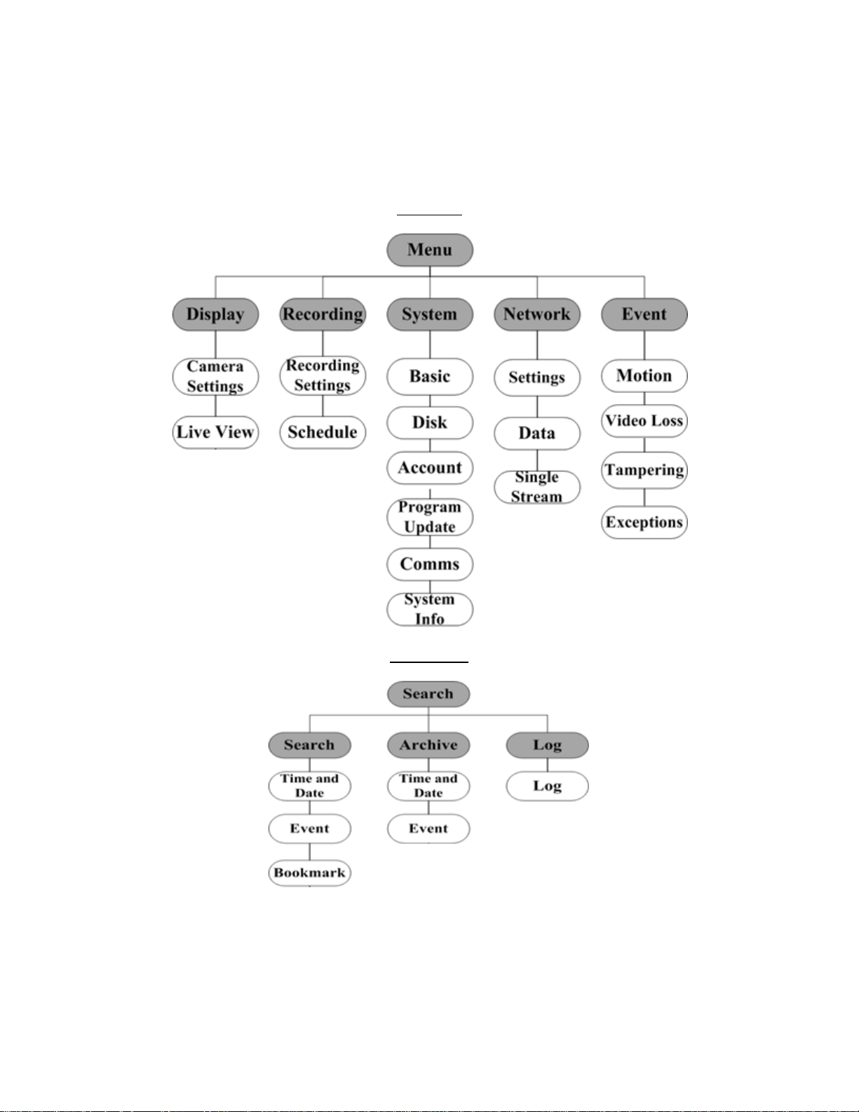
1.5 Menu Structure
The menu structure of the DVR is shown as below:
Main Menu
Search Menu
22

C H A P T E R 2
Introduction
23
No.
Name
Function Description
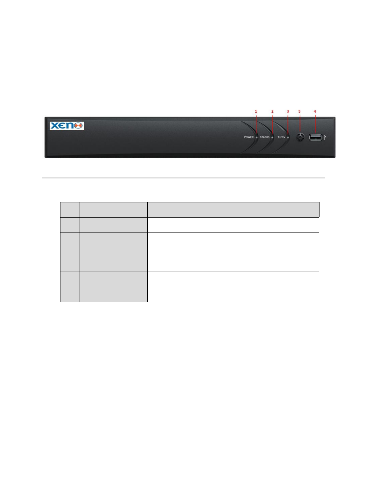
1
POWER
POWER indicator turns green when DVR is powered up.
2
STATUS
STATUS indicator lights in red when HDD is reading/writing.
3
Tx/Rx
Tx/Rx indictor blinks green when network connection is functioning
properly. 4 USB Interface
Connects USB mouse or USB flash memory devices.
5
IR Receiver
Receiver for IR remote.
2.1 Front Panel
The front panel of XDR5K4 DVR is shown in Figure 2.1.
Figure 2.1 Front Panel
Table 2.1 Description of the Front Panel
24

Name
Action
Description
Left-Click
Single-Click
Live view: Select channel and show the quick set menu.
Menu: Select and enter.
Double-Click
Live view: Switch between single-screen and multi-screen.
Click and Drag
PTZ control: pan, tilt and zoom.
Tamper-proof, privacy mask and motion detection: Select target
area.
Digital zoom-in: Drag and select target area.
Live view: Drag channel/time bar.
Right-Click
Single-Click
Live view: Show menu.
Menu: Exit current menu to upper level menu.
Scroll-Wheel
Scrolling up
Live view: Previous screen.
Menu: Previous item.
Scrolling down
Live view: Next screen.
Menu: Next item.
2.2 USB Mouse Operation
A regular 3-button (Left/Right/Scroll-wheel) USB mouse can also be used with this DVR. To use a USB mouse:
1. Plug USB mouse into one of the USB interfaces on the front panel of the DVR.
2. The mouse should automatically be detected. If in a rare case that the mouse is not detected, the possible
reason may be that the two devices are not compatible, please refer to the recommended the device list from
your provider.
The operation of the mouse:
Table 2.1 Description of the Mouse Control
25
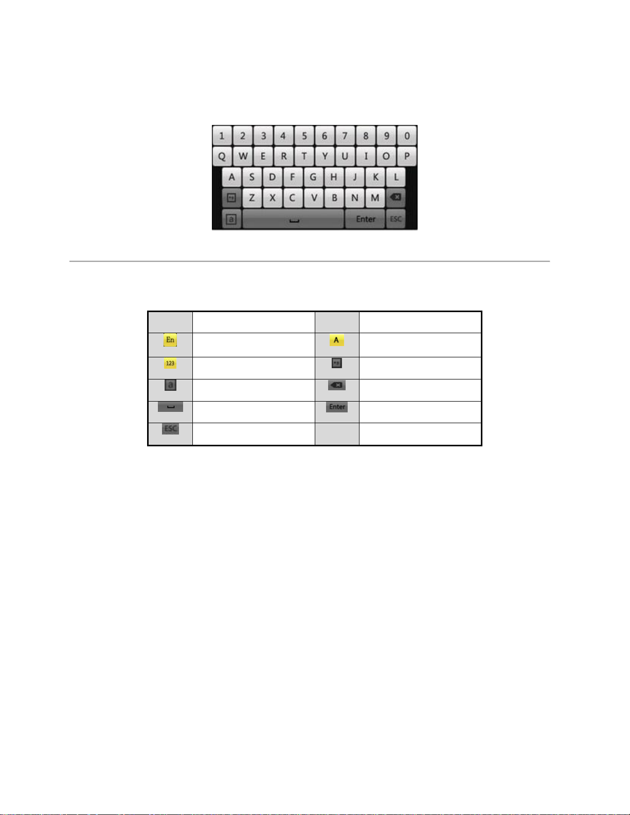
Icons
Description
Icons
Description
English
Capital English
Numbers
Symbols
Lowercase/Uppercase
Backspace
Space
Enter
Exit
2.3 Input Method Description
Figure 2.2 Soft Keyboard
Description of the buttons on the soft keyboard:
Table 2.2 Description of the Soft Keyboard Icons
26
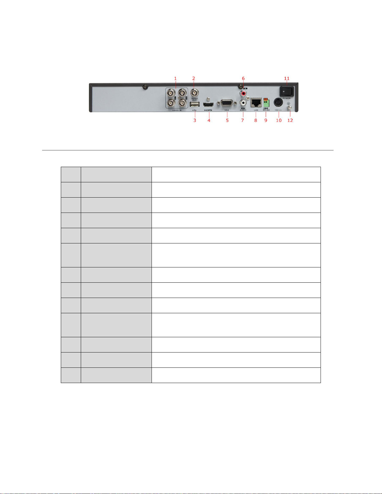
No.
Item
Description
1
VIDEO IN
BNC connector for analog video input.
2
VIDEO OUT
BNC connector for video output.
3
USB Interface
Connects USB mouse or USB flash memory devices.
4
HDMI
HDMI video output.
5
VGA
DB15 connector for VGA output. Display local video output and
menu.
6
AUDIO IN
RCA connector for audio input.
7
AUDIO OUT
RCA connector for audio output.
8
LAN Interface
Connector for LAN (Local Area Network).
9
RS-485 Interface
Connector for RS-485 devices. Connect the D+ and D- terminals
to T+ and T- of PTZ receiver respectively.
10
12V
12VDC power supply.
11
POWER
Switch for turning on/off the device.
12
GND
Ground (needs to be connected when DVR starts up).
2.4 Rear Panel
Table 2.4 Descriptions of the Rear Panel Interfaces
Figure 2.3 Rear Panel
27

2.5 Starting Up and Shutting Down the DVR
Purpose:
Proper startup and shutdown procedures are crucial to exptend the life of the DVR.
Before you start:
Check that the voltage of the power supply is the same with the DVR’s requirement, and the ground connection is
working properly.
Note:By default the DVR boots to all-day recording.
Starting up the DVR:
Steps:
1. Check the power supply is plugged into an electrical outlet. It is HIGHLY recommended that an Uninterruptible
Power Supply (UPS) be used in conjunction with the device.
2. Press the POWER button on the rear panel. The Power indicator LED should turn green indicating that the unit
begins to start up.
Shutting down the DVR
Steps:
1. Enter the Shutdown menu.
Menu > System->Basic->Shutdown
Figure 2.4 Shutdown Menu
2. Click the Shutdown button.
3. Click the Yes button.
Rebooting the DVR
28

In the Shutdown menu, you can also reboot the DVR.
Steps:
1. Enter the Shutdown menu by clicking Menu > System->Basic->Shutdown
2. Click the Reboot button to reboot the DVR.
29

C H A P T E R 3
Getting Started
30
 Loading...