

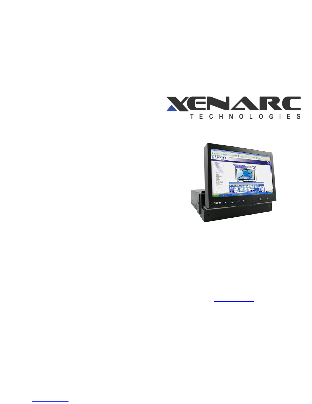
700IDT In-dash Touchscreen VGA LCD Monitor
Owner’s Records
The model and serial numbers are located on the rear of the unit. Please record these
numbers in the spaces provided below, as well as the dealer name, address, and
telephone number. Please refer to these records whenever speaking to your dealer
regarding this product.
Model # _______________________ Serial # ______________________
Dealer Name _________________________________________________
Street Address ________________________________________________
City ___________________ State _______________ Zip ____________
Phone # ( ) _________________Purchase Date ____/____/____
www.xenarc.com

2
NOTE
NOTE 1: If you are trying to connect the monitor to a laptop computer, please make
sure to enable the 15-Pin D -SUB external monitor output located at the back of your
laptop computer. Some laptop computers have three modes: Laptop Display Only,
Laptop Display plus External Monitor, and External Monitor Only. If this is the case,
please switch to the External Monitor Only mode.
NOTE 2: Touch Screen device driver must be installed onto your computer in order for
the Touch Screen to become functional. Xenarc Technologies uses 4-Wire Resistive
Touch Screen panels in the 700IDT monitor. Touch Screen drivers and software for
different operating systems can be found in the included CD-ROM disc. You can refer
to this manual for a walkthrough of Touch Screen Driver installation under Microsoft
Windows XP. You can find other instruction manuals inside the folder named “Doc”
on the CD.
NOTE 3: The maximum voltage supported by the monitor is 24V DC. Feeding the
monitor with higher voltage will damage the monitor and void the warranty. Please use
a fused power source if you decide to wire the monitor directly to your car’s electrical
system. It is also crucial that you check the polarity of the connection.
NOTE 4: If the monitor is not displaying the VGA signal properly, the VGA signal
might be out of range. Try changing your display refresh rate to 60, 70, 72, or 75Hz.
NOTE 5: Please note that the LCD screen is made with high-precision technology.
However, black points or bright points of light (red, blue, or green) may appear
constantly on the LCD screen, and irregular colored stripes or brightness may appear on
the LCD screen. This is not malfunction. (Effective dots: more than 99.999%)
NOTE 6: Make sure your monitor has a Xenarc Laser Hologram sticker to validate the
authenticity of your monitor.
For Technical Support, please contact us at:
Xenarc Technologies Corp.
2770 S. Harbor Blvd., Unit A
Santa Ana, CA 92704
TEL: 714-546-1018
Toll Free: 888-656-6536
E-mail: service@xenarc.com
URL: www.xenarc.com
14
8. Click Finish to finish the installation. You will be asked to restart your
computer.
9. Remove the CD and Restart your computer. After Windows XP is finished
loading, connect the 700TS or 700TSV USB cable to one of your computer’s
USB Ports.
10. Windows XP will start “Found New Hardware Wizard” automatically upon
detection of the USB Touch Controller. Click on Next to continue.
11. Click on Next to continue.
12. Click Finish to finish Setup. Your Touchscreen is ready to use now. You can
click on the icon Touchkit located on your desktop to launch the Touchscreen
program for various settings and adjustments.
3
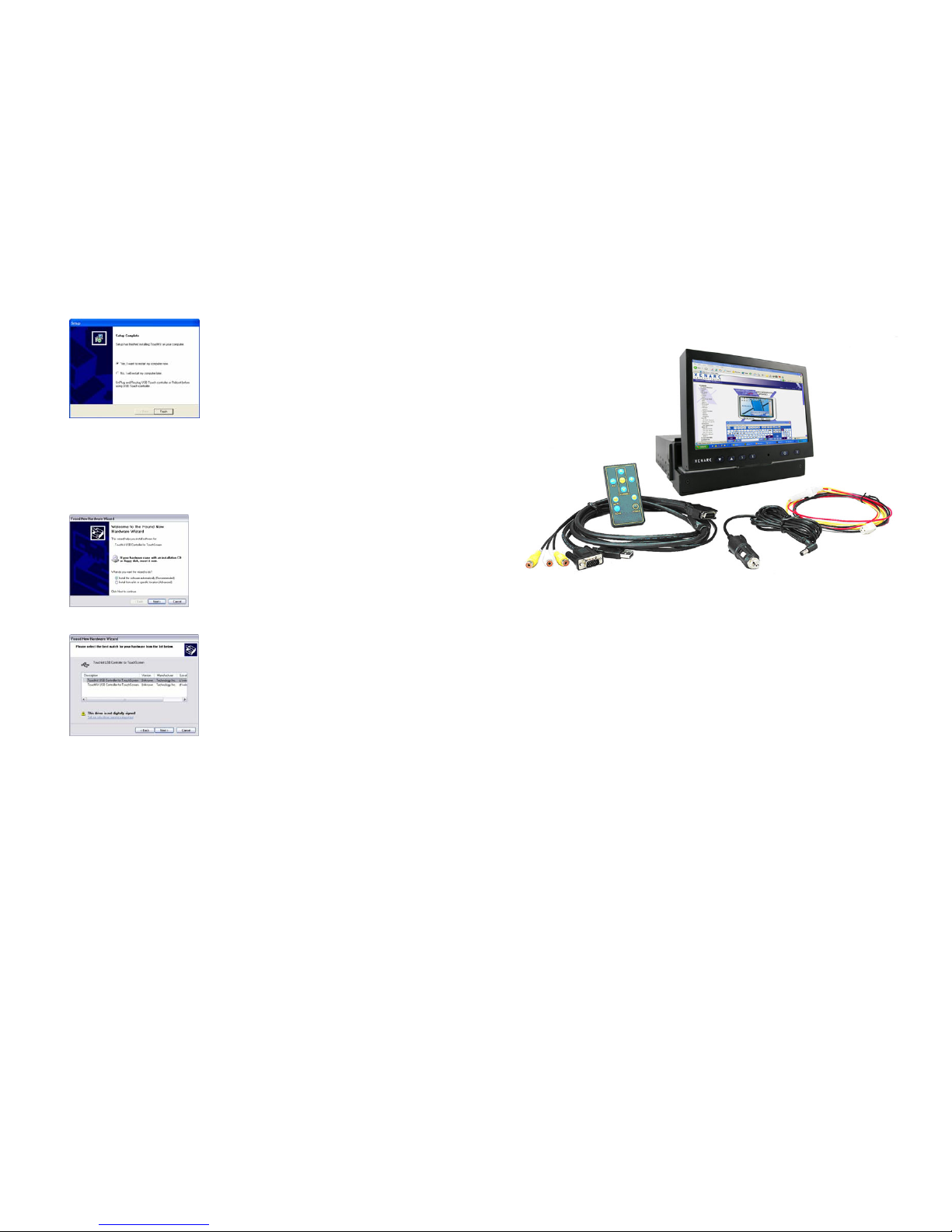
Package contents
1. 7” In-Dash Touch Screen monitor
2. Monitor cable - monitor to VGA (15 pin) and 2 x Composite
Video
3. Power cable
4. Cigarette lighter car adaptor
5. Remote control
* User Manual and Touch Screen Driver CD are included

4
7” In-Dash Touch Screen Monitor package contents
1. 7” In-Dash Touch Screen Monitor Main Unit
2. Trim Plate
3. Sleeve
700IDT Overview
1. Front View
13
4. Select the Rotating Monitor Utility and/or the Shutdown Utility if you want to
install them and click on Next to continue. The Rotating Monitor Utility
allows you to rotate your display while the Shutdown Utility provides you
with one-click shutdown.
5. Click Next to accept the Destination Directory default, shown below. Click on
Browse to change Destination Directory.
6. Click Next to accept the Program Folder default, shown below. Files will then
start to be copied to your computer.
7. When the warning that says this software has not passed Windows Logo test,
please click on Continue Anyway to continue the installation. File will
continue to be copied to your computer.
12
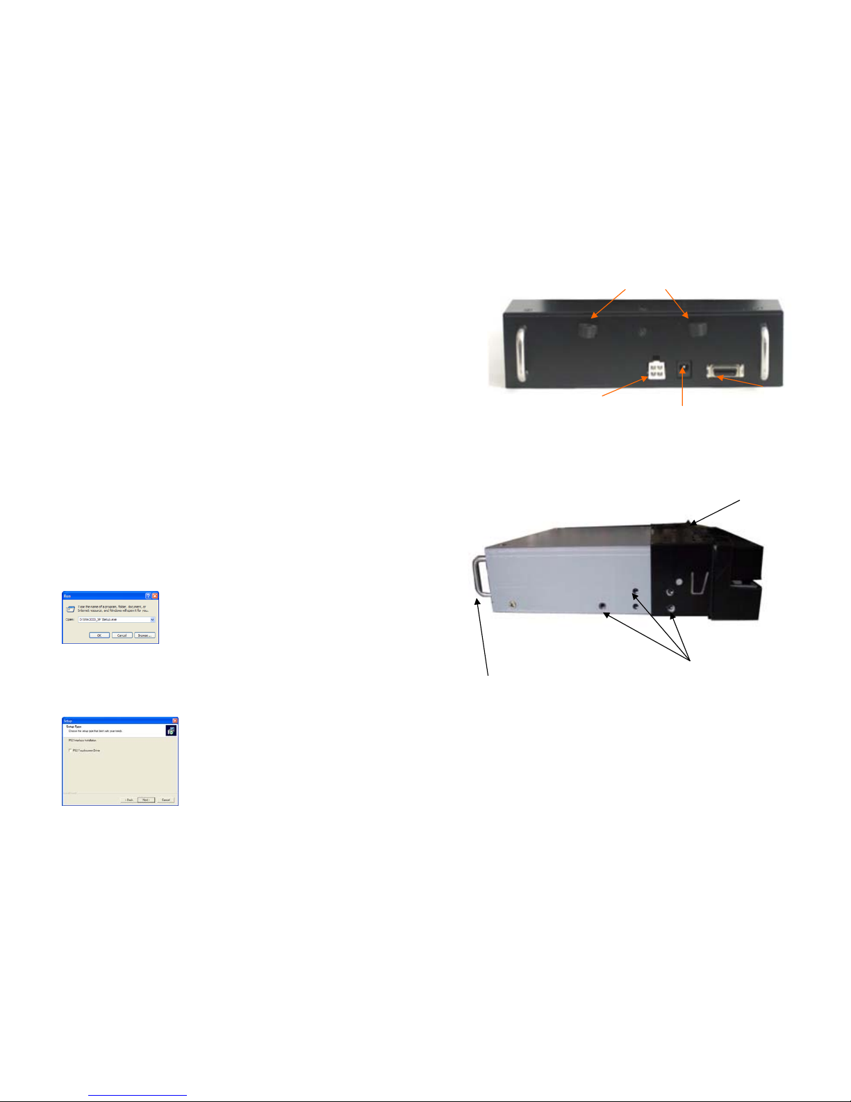
Connect signal source
1. Connect the 20-PIN connector on the black monitor cable to the back of the
700IDT. Route the cable through the dash to your PC.
2. Connect the D-Sub15 15-PIN VGA connector to your computer’s monitor output.
3. Connect the Yellow RCA plug labeled 1 and 2 to your composite video sources if
required (e.g. Video Game console, Camera, DVD-Player, etc.) The white RCA
plug labeled 3 is non-functional.
4. Connect the USB connector to your computer’s USB port after you have installed
the Touch Screen driver.
Install the Touch Screen Driver for Microsoft Windows XP:
Here is a simple walk through of Windows XP Touch Driver Installation for 800TSV.
You can skip this step if you have the 800YV.
1. Click on Start, Run, and Enter D:\Win2000_XP \Setup.exe (Please change the
drive letter corresponding to the drive containing the installation CD). Click
OK.
2. The Install Wizard window appears. Click Next.
3. Click Next to continue. Please leave the check box next to “PS2 Touchscreen
Driver” unchecked.
5
2. Rear View
3. Side View
Signal Cable socket
Screw holes for
Mounting Sleeve
Sleeve
6
4. Swivel Left/Right 150
Swivel Left 150 Swivel right 150
- Hold the top of the
monitor with both
hands
- Push and pull as
illustrated
- Hold the top of the
monitor with both
hands
- Push and pull as
illustrated
11
Method one: Power the unit through Cigarette lighter:
- Connect the power cable with one yellow wire, one red wire, and one black
wire to the back of the 700IDT. Connect the Red and Yellow wires together
and plug the cigarette lighter adaptor into your car’s cigarette lighter socket.
Method two: Power the unit through your car’s electrical system:
- Connect the power cable with one yellow wire, one red wire, and one black
wire to the back of the 700IDT.
Connect the Power Cable:
Connecting the leads
– Twist the Core
wires when
connecting
Solder the
core wires to
connect them
Caution:
To prevent short – circuit, cover
the terminals of the UNUSED
leads with insulating tape
* Screw and
connector Not
In
cluded
Ignition
Switch
Fig.1
Fuse Block
Connect Black wire (Ground) to metallic
body or chassis
Connect Yellow wire (+) to a live terminal
in the fuse block (Constant 12V DC)
Connect Red wire (VCC) to an
accessory terminal in the fuse block
(
Switched 12V DC
)

10
In-dash Monitor installation:
1. Remove the trim plate and sleeve
2. Install the sleeve into the dashboard
3. After the sleeve is correctly installed into the dashboard, bend the
appropriate tabs to hold the sleeve firmly in place
4. Slide the main unit into the sleeve
5. Apply screws (not included) to secure the unit
6. Re-attach the Trim Plate
7. To slide out the In-Dash Monitor, press the front panel firmly towards
dashboard (as the direction illustrated) and release.
1
2
3
4
5
6
7
Dashboar
d
7
External Buttons, Hot keys description:
Note1: The OSD Menu is only available when a video source is present.
Note2: The Hot keys are only available while the OSD menu is off.
“M”– Stands for Menu. This button is for OSD menu on/off toggling.
“S” – Stands for Select. Use this button for selection while OSD menu is on. Use
this button as a hot key to switch video channel directly when OSD menu is
off, following this rotation: VGA ->Video1 -> Video2 ->VGA.
“/\” – Stands for Increase. Use this button to increase value while OSD menu is
on.
“\/” – Stands for Decrease. Use this button to decrease value while OSD menu is
on.
Primary On Screen Display functions description:
The Primary OSD can be turn on by pressing the button “M”.
Bright
- Adjust brightness by pressing the Increase/Decrease buttons. Increase the
number for higher brightness. Decrease the number for lower brightness.
Contrast
- Adjust contrast by pressing the Increase/Decrease buttons. Increase the
number for higher contrast. Decrease the number for lower contrast.
Horz Pos
- Adjust Horizontal position by pressing the Increase/Decrease buttons.
Vert Pos
- Adjust Vertical position by pressing the Increase/Decrease buttons.
Phase
- Adjust CLK phase alignment by pressing the Increase/Decrease buttons.
(Image flicker can by avoided by CLK phase adjustment. This function is valid
on the VGA mode only)
Auto Detect
- Adjust display automatically. (Valid on the VGA mode only)
Secondary On Screen Display functions description:
The Secondary OSD can be turn on by pressing “M” twice.
Backlight
- Adjust the CCFL backlight output level.
8
Default
- Load default setting.
AV2 First
- Set whether to have monitor switch to Video Input 2 automatically if a signal
is present. Good for car reverse monitoring system.
Scaler
- Set the display mode to 16:9 or 4:3. Set it to 4:3 if your video signal is in 4:3
aspect ratio and you don’t want the display to be stretched out. Default is
16:9.
External Specifications:
Video Source Input
• RGB analog male connector (15-Pin D-SUB) x 1
• RCA composite video female connector x 2
Audio Source Input
• RCA audio female connector x 1 is of no function
Touch Panel I/O
• USB connector x 1
Power Source Input
• Single 12V DC_IN (Supports 11V ~ 24V)
External Buttons Input
• OSD buttons for Menu/Select/Increase/Decrease
• PWR button for power switch
Internal Specifications:
LCD Module : 7” Digital TFT LCD
LCD Native resolution : 800 x 480 (2400 x 480 dots)
Pixel Pitch : 0.1905 x 0.1905 mm
LCD Panel Brightness : 400 NIT
Contrast : 150 : 1
Response Time : 56ms
Viewing Angle : Vertical: 90 / Horizontal: 120
Supported display resolution : 640 x 480 ~ 1600 x 1200
Supported refresh rate : 60 ~ 75 Hertz
Video Format : NTSC/PAL Auto-detect
Colors : 18-b it (262,144 Colors)
Inverter Inside : Adjustable output w/ Power Mgmt
9
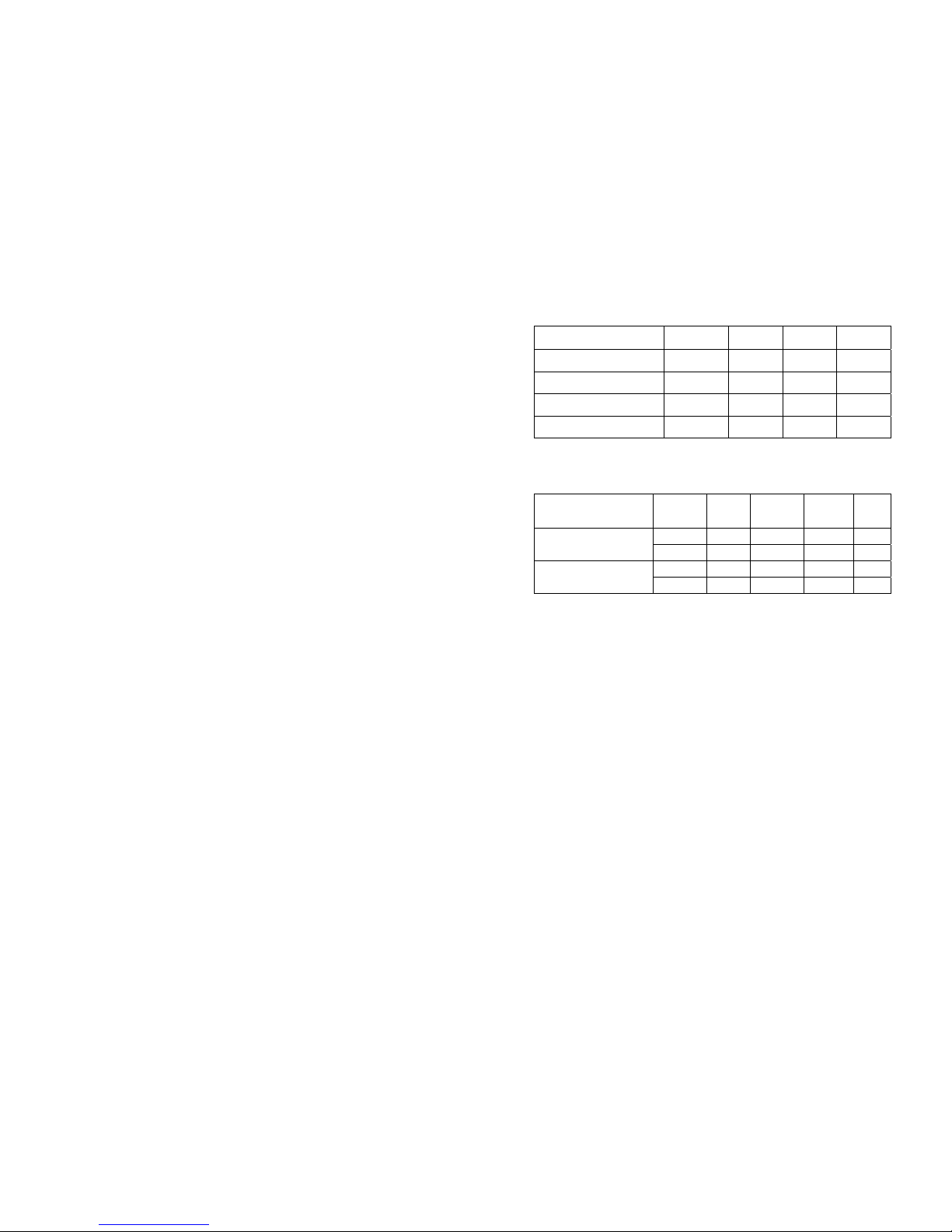
Electrical Characteristics:
Absolute Maximum Ratings:
Parameter Symbol Min Max Unit
Analog Signal Input Level Signal 0 1.4 Vp-p
Power Supply DC IN 11 24 V
Digital Signal Input Level - - 5+0.3 V
Operation Temperature - -14 176 ºF
Recommended Operating Conditions:
Parameter
Symbol Min Typical Max
Unit
Signal 0.5 0.7 1.2 Vp-p Analog Signal Input Level
RGB/Composite AV
DC GND - 0.3 V
DC IN 11 12 24 V
Power Supply
Current 0.59 0.72 0.74 A
Power Consumption:
Standby mode < 0.3W
Suspend mode < 3W
Continue mode < 4W (w/o inverter), <9W (w/ inverter)
Inverter output specifications:
Power supply: +12V
Lamp frequency: 50KHz
Max output open voltage: 1300Vrms
Power consumption: < 5W
 Loading...