


Slim-Link® W eb Server-Controller
June 2001
Micro-Controller incorporates Web-Enabled, Real-time Operating System
DESCRIPTION
The Slim-Link family of Web Server-Controller products
provides the ideal core technology for Internet enabled
instruments and control systems. The Slim-Link Web Server
Controllers are based on a 40 MHz AMD186ES microcontroller and feature MicroRTOS, a web enabled, real-time
operating system developed spedifically for control system
applications. MicroRTOS is embedded into each Slim-Link
Web Server-Controller product with no additional cost or
licensing fees.
MicroRTOS
MicroRT OS was created to simplify the process of designing a
web enabled instrument or control system. This is
accomplished by integrating a Preemptive Real-time Kernel,
thin Web Server, and TCP/IP Stack into the fully-functioning
operating system. The designer can then concentrate on the
design of his application rather than integrating source codes
from disparate applications. Three editions of MicroRT OS are
available to support your application; the Basic edition, PPP
Client Edition with Point-to-Point protocol for dial out
applciations and the PPP Server Editon with Point-to-Point
protocol for in bound dial-up applications.
Models
Six models of the Slim-Link
currently offered. Each model is described below .
A WC86: Features the Basic Edition of MicroRT OS and 34
Digital I/O Lines
AWC86A: Features the Basic Edition of MicroRTOS with
both Analog and Digital I/O Lines
AWC86C: Features the PPP Client Edition of MicroRTOS
and 34 Digital I/O Lines
®
Web Server-Controller are
CONTROLLER FEATURES
* Fully integrated microcontroller based on a 40 MHz AM186
Processor.
* 34 I/O function pins software selectable and configurable;
- Two serial ports (RS232-TTL)
- Eight 12-bit analog inputs; Two 12-bit analog outputs
- Digital I/O, Timers, IRQs
* 512KByte Flash memory for user application code, Web
page layouts and control data;
* 512KByte SRAM for run time code and data buffering
* Development kits available
MicroRTOS™ OPERATING SYSTEM FEA TURES
* Multi-User, Multi-Task, Real-time Operation
Preemptive real-time kernel for multi-tasking applications
*
* TCP/IP Stack supported by Ethernet datalink/physical layer
* Multi-user console tasks provides a user development and
application platform
AWC86AC: Features the PPP Client Edition of MicroRTOS
with both Analog and Digital I/O Lines
AWC86S: Features the PPP Server Edition of MicroRTOS
and 34 Digital I/O Lines
AWC86AS: Features the PPP Server Edition of MicroRTOS
with both Analog and Digital I/O Lines
SOFTW ARE DESIGN TOOLS
* Compatible with Borland Turbo C++ versions 3.0, 3.1, 4.5
and 4.52 and Microsoft Visual C++ Versions 1.0 to 1.52.
P ACKAGING FEATURES
* Small size: 2.75" L x 1.38" W x 0.42” H
* Sturdy, encapsulated construction seals circuits from
harsh environment;
* Industrial temperature range available (-40C to +85C)
Advanced W eb Communication (1) Slim-Link® Server
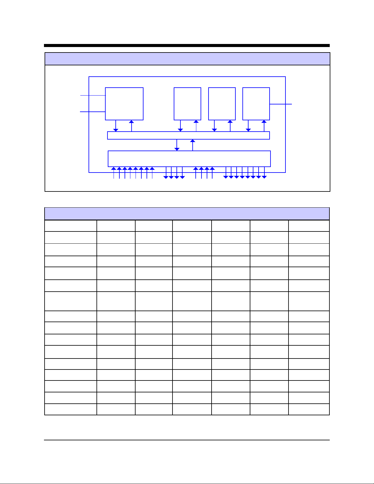
Slim-Link® Server Functional Block Diagram
Serial Port 1
Serial Port 0
AM186ES-40
CPU
System Bus
Analog/Digital I/O’s T imers, IRQ’s
Slim-Link® Server Feature Table
FEA TURE
CPU
Flash
RAM
A WC86 A WC86C A WC86 A WC86A A WC86AC A WC86AS
AM186-ES AM186-ES AM186-ES AM186-ES AM186-ES AM186-ES
512 KBytes 512 KBytes 512 KBytes 512 KBytes 512 KBytes 512 KBytes
512 KBytes 512 KBytes 512 KBytes 512 KBytes 512 KBytes 512 KBytes
Flash
Memory
512KB
SRAM
512KB
10Base-T
Ethernet
RJ45 to LAN
Network I/F
Programmable I/O
Dedicated Digital
Inputs
Analog Inputs
Analog Outputs
Real-Time Clock
MicroR TOS 2.0
TCP/IP Stack
PPP Client
PPP Server
W eb Server
T elnet Server
10BASE-T 10BASE-T 10BASE-T 10BASE-T 10BASE-T 10BASE-T
26 26 26 22 22 22
888---
---888
---222
N/A N/A N/A Y e s Y e s Y e s
Basic Edition Client Edition Server Edition Basic Edition Client Edition Server Edition
Yes Yes Yes Yes Yes Yes
No Y es No No Y es No
No No Y es No No Y es
Yes Yes Yes Yes Yes Yes
Yes Yes Yes Yes Yes Yes
Advanced W eb Communication (2) Slim-Link® Server
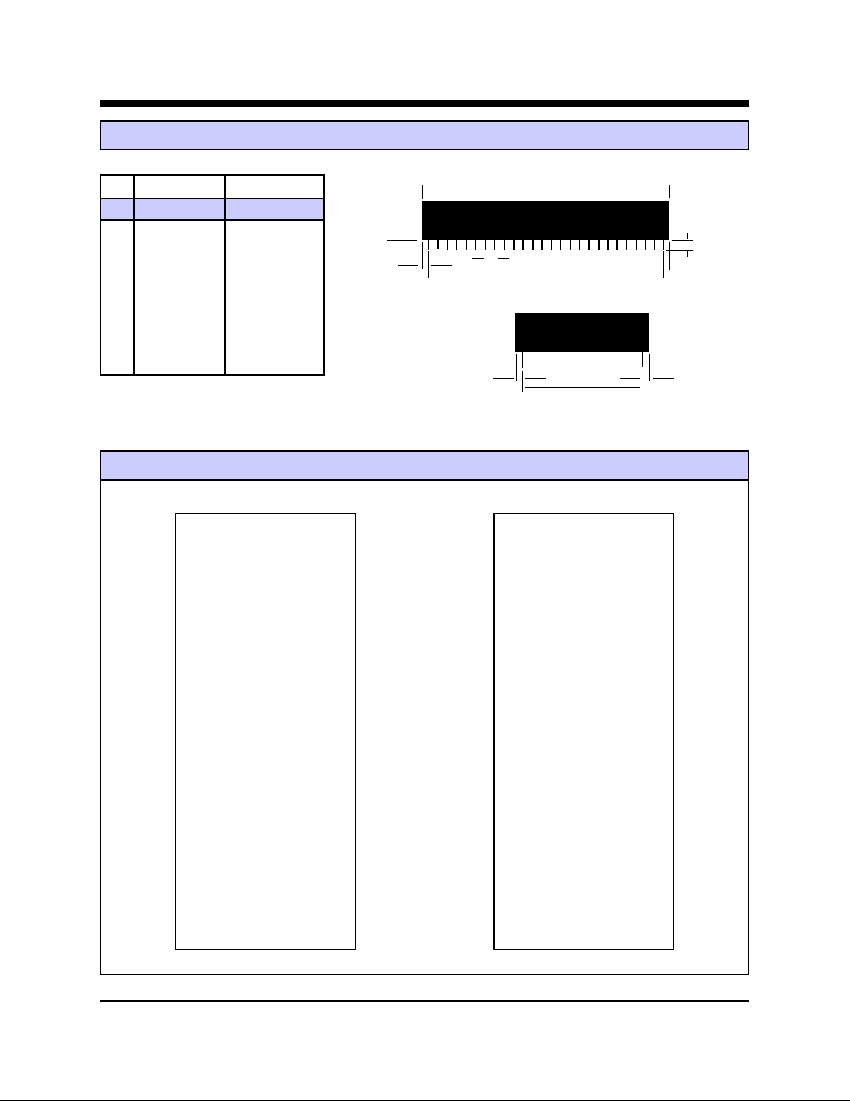
Slim-Link® Server Mechanical Specifications
INCHES METRIC(MM)
A
PIN MIN MAX MIN MAX
A 2.740 2.760 69.60 70.10
B
F
B 0.420 0.430 10.67 10.92
C 1.370 1.390 34.80 35.31
J
H
E
H
D 1.190 1.210 30.23 30.73
E 2.490 2.510 63.25 63.75
C
F 0.125 0.200 3.18 5.08
G 0.080 0.100 2.03 2.54
H 0.115 0..135 2.92 3.43
J 0.090 0.110 2.29 2.79
G
D
G
AWC86 and AWC86A Pin Configurations
AWC86 AWC86A
TD+ O 1 52 O VCC TD+ O 1 52 O VCC
TD- O 2 51 O DIO21(TIN1) TD- O 2 51 O DIO21(TIN1)
RD+ O 3 50 O DIO20(TOUT) RD+ O 3 50 O DIO20(TOUT1)
RD- O 4 49 O DIO19(DT/R) RD- O 4 49 O DIO19(DT/R)
48 O DIO18 48 O DIO18
NSTAT O 6 47 O DIO17 NSTAT O 6 47 O DIO17
NXMT O 7 46 O DIO16(TOUT0) NXMT O 7 46 O DIO16(TOUT0)
N/C O 8 45 O DIO15(TIN0) N/C O 8 45 O DIO15(TIN0)
N/C O 9 44 O DIO14(INT5) N/C O 9 44 O DIO14(INT5)
DIO0(TXDA) O 10 43 O DIO13(INT6) DIO0(TXDA) O 10 43 O DIO13(INT6)
DIO1(RXDA) O 11 42 O DIO12 DIO1(RXDA) O 11 42 O DIO12
DIO2(/RTSB) O 12 41 O DIO11 DIO2(/RTSB) O 12 41 O DIO11
DIO3(/CTSB) O 13 40 O DIO10 DIO3(/CTSB) O 13 40 O DIO10
DIO4(TXDB) O 14 39 O DIO25 DIO4(TXDB) O 14 39 O D/A1
DIO5(RXDB) O 15 38 O DIO24 DIO5(RXDB) O 15 38 O D/A0
DIO6 O 16 37 O DIO23 DIO6 O 16 37 O MUXOUT
DIO7 O 17 36 O DIO22 DIO7 O 17 36 O ADCIN
DIO8(INT2) O 18 35 O DIN7 DIO8(INT2) O 18 35 O AIN7
DIO9(INT4) O 19 34 O DIN6 DIO9(INT4) O 19 34 O AIN6
NMI O 20 33 O DIN5 NMI O 20 33 O AIN5
INT1 O 21 32 O DIN4 INT1 O 21 32 O AIN4
INT3 O 22 31 O DIN3 INT3 O 22 31 O AIN3
CLKOUT O 23 30 O DIN2 Vref O 23 30 O AIN2
RESETOUT O 24 29 O DIN1 V.BAT O 24 29 O AIN1
/RESET O 25 28 O DIN0 /RESET O 25 28 O AIN0
GND O 26 27 O GND DGND O 26 27 O AGND
Advanced W eb Communication (3) Slim-Link® Server

Slim-Link® Server Pin Descriptions
Pin Signal Model Description
1 TD+ All TD+ is the positive lead of the 10Base-T transmit pair . The transmit pair presents
an impedance of 100 ohms.
2 TD- All TD- is the negative lead of the 10Base-T transmit pair. The transmit pair presents
an impedance of 100 ohms.
3 RD+ All RD+ is the positive lead of the 10Base-T receive pair. The receive pair presents
an impedance of 100 ohms.
4 RD- All RD- is the negative lead of the 10Base-T receive pair . The receive pair presents
an impedance of 100 ohms.
5 All No Pin
6 NSTAT All NSTAT is an active low output which indicates the status of the LAN connection
to the Slim-Link® Server. A low indicates the LAN connection is active. The
NSTAT output can sink up to 12 milliamps to drive an LED indicator.
7 NXMT All NXMT is an active low output. It goes low to indicate that the Slim-Link
Server is transmitting data onto the Local Area Network. The function of this
signal can be altered in the Ethernet Controller’s ISA Controller Status Register
7. The NXMT output can sink up to 12 milliamps to drive an LED indicator.
®
8 N/C All No Connection; reserved for future use.
9 N/C All No Connection; reserved for future use.
10 DIO0(TXDA) All This pin provides access to Programmable Input/Output 27 from the AMD186
controller. This I/O line can also be used as the Transmit Data input for Serial
Port A. Hardware Flow Control is not available on Serial Port A.
11 DIO1(RXDA) All This pin provides access to Programmable Input/Output 28 from the AMD186
controller. This I/O line can also be used as the Received Data output for Serial
Port A. Hardware Flow Control is not available on Serial Port A.
12 DIO2(/R TSB) All This pin provides access to Programmable Input/Output 20 from the AMD186
controller. This I/O line can also be used as the Request to Send output for
Serial Port B. Request to Send is used for hardware flow control. The Slim-
Link® Server deactivates Request to Send to stop the flow of data from the
peripheral equipment.
13 DIIO3(/CTSB) All This pin provides access to Programmable Input/Output 21 from the AMD186
controller. This I/O line can also be used as the Clear to Send input for Serial
Port B. Clear to Send is used for hardware flow control. When Clear to Send is
inactive, the Slim-Link® Server will not transmit data to the peripheral equipment.
14 DIO4(TXDB) All This pin provides access to Programmable Input/Output 22 from the AMD186
controller. This I/O line can also be used as the Transmit Data input for Serial
Port B.
15 DIO5(RXDB) All This pin provides access to Programmable Input/Output number 23 from the
AMD186 controller. This I/O line can also be used as the Transmit Data input
for Serial Port B.
Advanced W eb Communication (4) Slim-Link® Server

®
Slim-Link
Server Pin Descriptions (continued)
Pin Signal Model Description
16 DIO6 All This pin provides access to Programmable Input/Output 24 from the AMD186
controller.
17 DIO7 All This pin provides access to Programmable Input/Output 25 from the AMD186
controller.
18 DIO8(INT2) Al l This pin provides access to Programmable Input/Output 31 from the AMD186
controller. It also provides the input for Interrupt Request 2 to the Slim-Link
Server.
19 DIO9(INT4) Al l This pin provides access to Programmable Input/Output 30 from the AMD186
controller. It also provides the input for Interrupt Request 4 to the Slim-Link
Server.
20 NMI All This input provides access to the non-maskable interrupt to the microcontroller .
This is the highest priority interrupt available on the Slim-Link® Server
21 INT1 All INT1 provides the input for Interrupt Request 1 to the to the microcontroller.
22 INT3 All INT3 provides the input for Interrupt Request 3 to the to the microcontroller.
23 CLKOUT AWC86 This output provides the clock signal for the rest of the embedded control system
in the AWC86. Depending upon the value set in the System Configuration
Register of the AMD186 controller CLKOUT can be at 40 MHz, at the Power-
Save frequency , or may be tri-stated. The Power-Save frequency is programmable
from 1/2 (20 MHz) to 1/128 (312.5 KHz) of the system clock
VREF AWC86A This input provides the reference voltage for the Slim-Link® Server analog inputs.
VREF should not exceed VCC by more than 50 millivolts.
24 RESETOUT AWC86 This output provides an active high reset pulse for the complete embedded
control system. The duration of the reset pulse is typically 13 milliseconds. The
reset pulse is sent each time power is applied to the AWC86 or the /RESET
signal is driven low .
®
®
V.BAT AWC86A This input the battery backup voltage for the AWC86A Real-Time Clock. A
minimum of two volts must be maintained on VCC1 to maintain the Real-Time
Clock.
25 /RESET ALL This input allows an the Slim-Link® Server to be reset from an external source.
Reset must be held low for a minimum of one millisecond to initiate a Slim-Link
Server reset.
26 DGND ALL DGND provides the reference ground for the Slim-Link® Server’s Digital I/O
signals.
27 GND AWC86 This signal provides the reference ground for the AWC86 I/O signals.
AGND A WC86A This signal provides the reference ground for the A WC86A Analog I/O signals.
Advanced W eb Communication (5) Slim-Link® Server

®
Slim-Link
Server Pin Descriptions (continued)
Pin Signal Model Description
28 DIN0 AWC86 The AWC86 buf fers this digital data input and passes it to the AMD186 Address
and Data Bus bit 0. The buffer for this input is controlled by Programmable
Input/Output 2 from the AMD186 controller.
AIN0 AWC86A AIN0 provides one of 8 analog input channels to the AWC86A. The integral
Analog to Digital Convertor creates a serial digital representation and sends it to
Programmable Input/Output 26 of the AMD186 controller.
29 DIN1 AWC86 The AWC86 buf fers this digital data input and passes it to the AMD186 Address
and Data Bus bit 1. The buffer for this input is controlled by Programmable
Input/Output 2 from the AMD186 controller.
AIN1 AWC86A AIN1 provides one of 8 analog input channels to the AWC86A. The integral
Analog to Digital convertor creates a serial digital representation and sends it to
Programmable Input/Output 26 of the ABD186 controller.
30 DIN2 AWC86 The AWC86 buf fers this digital data input and passes it to the AMD186 Address
and Data Bus bit 2. The buffer for this input is controlled by Programmable
Input/Output 2 from the AMD186 controller.
AIN2 AWC86A AIN2 provides one of 8 analog input channels to the AWC86A. The integral
Analog to Digital Convertor creates a serial digital representation and sends it to
Programmable Input/Output 26 of the AMD186 controller.
31 DIN3 AWC86 The AWC86 buf fers this digital data input and passes it to the AMD186 Address
and Data Bus bit 3. The buffer for this input is controlled by Programmable
Input/Output 2 from the AMD186 controller.
AIN3 AWC86A AIN3 provides one of 8 analog input channels to the AWC86A. The integral
Analog to Digital Convertor creates a serial digital representation and sends it to
Programmable Input/Output 26 of the AMD186 controller.
32 DIN4 AWC86 The AWC86 buf fers this digital data input and passes it to the AMD186 Address
and Data Bus bit 4. The buffer for this input is controlled by Programmable
Input/Output 2 from the AMD186 controller.
AIN4 AWC86A AIN4 provides one of 8 analog input channels to the AWC86A. The integral
Analog to Digital Convertor creates a serial digital representation and sends it to
Programmable Input/Output 26 of the AMD186 controller.
33 DIN5 AWC86 The AWC86 buf fers this digital data input and passes it to the AMD186 Address
and Data Bus bit 5. The buffer for this input is controlled by Programmable
Input/Output 2 from the AMD186 controller.
AIN5 AWC86A AIN5 provides one of 8 analog input channels to the AWC86A. The integral
Analog to Digital Convertor creates a serial digital representation and sends it to
Programmable Input/Output 26 of the AMD186 controller.
34 DIN6 AWC86 The AWC86 buf fers this digital data input and passes it to the AMD186 Address
and Data Bus bit 6. The buffer for this input is controlled by Programmable
Input/Output 2 from the AMD186 controller.
Advanced W eb Communication (6) Slim-Link® Server

Slim-Link® Server Pin Descriptions (continued)
Pin Signal Model Description
34 AIN6 AWC86A AIN6 provides one of 8 analog input channels to the AWC86A. The integral
Analog to Digital Convertor creates a serial digital representation and sends it to
Programmable Input/Output 26 of the AMD186 controller.
35 DIN7 AWC86 The AWC86 buf fers this digital data input and passes it to the AMD186 Address
and Data Bus bit 7. The buffer for this input is controlled by Programmable
Input/Output 2 from the AMD186 controller.
AIN7 AWC86A AIN7 provides one of 8 analog input channels to the AWC86A. The integral
Analog to Digital Convertor creates a serial digital representation and sends it to
Programmable Input/Output 26 of the AMD186 controller.
36 DIO22 AWC86 This pin provides access to Programmable Input/Output 29 from the AMD186
controller.
ADCIN AWC86A ADCIN provides the input to the Analog to Digital Convertor. This input is
normally tied to the MUXOUT line.
37 DIO23 AWC86 This pin provides access to Programmable Input/Output 26 from the AMD186
controller.
MUXOUT AWC86A MUXOUT is the output of the eight to one multiplexor which serves the eight
Analog Input lines on the A WC86A. This output is normally tied to ADCIN.
38 DIO24 AWC86 This pin provides access to Programmable Input/Output 15 from the AMD186
controller.
DA0 AWC86A This pin provides one of the two analog outputs (VoutA) from the Digital to
Analog Convertor Output integrated into the AWC86A. The digital data is
supplied by Programmable Input/Output 26 from the AMD186 controller.
39 DIO25 AWC86 This pin provides access to Programmable Input/Output 3 from the AMD186
controller.
DA1 AWC86A This pin provides one of the two analog outputs (VoutB) from the Digital to
Analog Convertor Output integrated into the AWC86A. The digital data is
supplied by Programmable Input/Output 26 from the AMD186 controller
40 DIO10 ALL This pin provides access to Programmable Input/Output 17 from the AMD186
controller.
41 DIO11 ALL This pin provides access to Programmable Input/Output 16 from the AMD186
controller.
42 DIO12 ALL This pin provides access to Programmable Input/Output 14 from the AMD186
controller.
43 DIO13(INT6) ALL This pin provides access to Programmable Input/Output 13 from the AMD186
controller. It also provides the input for Interrupt Request 6 to the Slim-Link
Server.
44 DIO14(INT5) ALL This pin provides access to Programmable Input/Output 12 from the AMD186
controller. It also provides the input for Interrupt Request 5.
®
Advanced W eb Communication (7) Slim-Link® Server

Slim-Link
®
Server Pin Descriptions (continued)
Pin Signal Model Description
45 DIO15(TIN0) ALL This pin provides access to Programmable Input/Output 11 from the AMD186
controller. It also provides the input for Timer 0.
46 DIO16(TOUT0) ALL This pin provides access to Programmable Input/Output 10 from the AMD186
controller. It also provides the output for Timer 0.
47 DIO17 ALL This pin provides access to Programmable Input/Output 6 from the AMD186
controller.
48 DIO18 ALL This pin provides access to Programmable Input/Output 5 from the AMD186
controller.
49 DIO19(DT/R) ALL This pin provides access to Programmable Input/Output 4 from the AMD186
controller. As DT/R, this controls the data flow through an external data-bus
transceiver. When DT/R is high, the AMD186 transmits data; the AMD186
receives data when DT/R is low .
50 DIO20(TOUT1) ALL This pin provides access to Programmable Input/Output 1 from the AMD186
controller. It also provides the output for Timer 1.
51 DIO21(TIN1) ALL This pin provides access to Programmable Input/Output 0 from the AMD186
controller. It also provides the input for Timer 1.
52 VCC ALL Plus 5 V olt Power for the Slim-Link® Server
Slim-Link® Server Absolute Maximum Ratings
VCC 5.5 Volts
DC Input Voltage -0.5 to +5.5 Volts
Storage Temperature Range -20C to +100C
Operating Temperature Range 0C to 70C (-40C to +85C Available)
Lead T emperature During Soldering 260 C for 2 seconds maximum
Slim-Link® Server Power Supply Characteristics
Symbol Parameter Min Typ M ax Units
VCC Supply Voltage 4.75 5.0 5.25 Volts
ICC Supply Current 250 milliamps
V.bat* Battery Voltage for Real-Time Clock 2.0 3.0 5.5 V olts
I.bat* Battery Current Draw 0.2 0.3 microamps
Vref A/D Reference Voltage 1.500 4.096 5.000 Volts
* External Battery Backup for Real-Time Clock
Advanced W eb Communication (8) Slim-Link® Server

Slim-Link® Server I/O Characteristics
Digital I/O Signals
Signal Mode Maximum Voltage Low Minimum Voltage High
Programmable I/O Lines
Digital Input INPUT 0.8 Volts 2.0 Volts
Interrupt Lines OUTPUT 0.8 Volts 2.0 Volts
Reset INPUT 0.8 Volts 2.4 Volts
NXMT INPUT 0.8 Volts 2.4 Volts
NSTAT OUTPUT 0.8 Volts 2.4 Volts
1
DIO22, DIO23, DIO24, and DIO25 are not provided on the AWC86. On the AWC86A these signals are used to
1, 2
INPUT 0.8 Volts 2.0 Volts
OUTPUT 0.45 Volts 2.4 Volts
control analog inputs and outputs.
2
DIO8, DIO9, DIO13, DIO14, include a 10K pull down resistor.
Analog I/O Signals (A WC86A only)
Signal Mode Maximum Voltage Minimum Voltage
Analog Inputs INPUT -0.3 Volts VCC+ .3 Volts
Analog Outputs OUTPUT 0.0 Volts 4.096 Volts
Network Interface Signals
Signal Description Impedance for Line Pair Maximum Loop Length
TD + Ethernet 10Base-T Transmit Data Positive 100 Ohms Transmit Pair 100 Meters
TD - Ethernet 10Base-T Transmit Data Negative 100 Ohms Transmit Pair 100 Meters
RD+ Ethernet 10Base-T Receive Data Positive 100 Ohms Receive Pair 100 Meters
Advanced W eb Communication (9) Slim-Link® Server

Slim-Link® Server Local Area Network Connection
The Slim-Link® Server integrates a 10Base-T connection.
An AMD AM79C961A Ethernet Controller is linked to
the AMD186 main controller to handle the local area
network interface. The AM79C961 provides both the
Ethernet Control functions and 10Base-T transceiver
facilities.
The integrated AM79C961A supports an IEEE 802.3 or
ANSI 8802-3 compliant 10Base-T network connection.
The ethernet controller handles all data framing,
addressing and error detection tasks, and manages
collision handling and avoidance.
Slim-Link® Server Serial Ports
The Slim-Link® Server includes a pair of serial ports for
local communications. These ports come directly from
the AM186 controller. Serial Port B supports hardware
flow control lines as well as transmit and received data.
Serial Port A supports only transmit and received data.
Serial Port A
Serial Port A corresponds to Serial Port 1 of the AM186
micro-controller. Serial Port A includes only the TXD
(Transmit Data) and RXD (Received Data) signals.
These signals are active low.
Serial Port A does not support Hardware Flow Control.
In-band flow control should be used instead. When using
in-band flow control, predefined XON and XOFF
characters serve as flow control signals from the
controller and peripheral. The equipment places an
XOFF character in the data stream when it can no longer
accept data. An XON character is sent when data traffic
can again be accepted.
Serial Port A Signal AM186 Signal
TXDA PIO27
RXDA PIO28
The AM79C961A operates in Bus Master mode
permitting it to directly address all memory locations. The
fixed Ethernet Physical address is stored in an on-board
EEPROM with other configuration data.
Serial Port B
Serial Port B corresponds to Serial Port 0 of the AM186
micro-controller. Serial Port B includes hardware flow
control lines RTS (Request to Send) and CTS (Clear to
Send) as well as TXD (Transmit Data) and RXD
(Received Data). All signals are active low.
The hardware flow control lines regulate the flow of data
between the Slim-Link® Server and its serial peripheral.
When both devices can receive data the RTS and CTS
lines remain active. The Slim-Link® Server should keep
RTS active as long as it can accept data from the
peripheral equipment. It should drop RTS to signal the
peripheral equipment that it cannot accept data on RXD.
The peripheral equipment will likewise manipulate CTS
to indicate when it is unable to accept data on TXD.
Serial Port B Signal AM186 Signal
TXDB PIO22
RXDB PIO23
RTSB PIO20
CTSB PIO21
Advanced W eb Communication (10) Slim-Link® Server

AWC86A Analog Outputs
The AWC86A includes two Analog Output pins. These
outputs are supported by a 12-bit internal digital to analog
convertor within the Slim-Link Server. Three of the
AM186 Programmable Input/Output lines are used to
support this function.
Digital to Analog Convertor
The Digital to Analog Convertor converts 24-bit serial
data bytes into two analog output signals. The serial data
is transmitted synchronously from the AM186 controller
to the Digital to Analog Convertor. The first 12 bits define
the level at DA0; the remaining 12 bits define the level at
DA1. The maximum output voltage on either analog
output is 4.095 volts, the Least Significant Bit equals 1
millivolt.
AWC86A Analog Input Lines
The Slim-Link® Server is available with 8 Analog Input
pins, AWC86A only. These inputs feed into a common
12-bit Analog to Digital Convertor, ADC. Three of the
Programmable Input/Output lines from the AMD186
support these analog inputs.
Analog to Digital Convertor, ADC
An integral Analog to Digital Convertor converts the
analog inputs to a serial digital data stream. The maximum
sampling rate of the ADC is 16.8 KHz. The ADC provides
12-bit resolution; the least significant bit equals .00122
volts.
The AWC86A multiplexes all eight analog inputs into a
single ADC under the control of the AMD186 controller.
With Programmable Input/Output 2 high the AMD186
controller sends the 4-bit multiplexor address on
Programmable Input/Output 26. When Programmable
Input/Output 2 is low , serial data flows from the ADC to
the AMD186 controller on Programmable Input/Output
26. The synchronizing clock for the data is provided by
the AMD186 on Programmable Input/Output 29.
The three signals which control the integral Digital to
Analog Convertor are PIO3, PIO26 and PIO29. Serial
data is presented to the digital to analog convertor on
PIO26. The serial data clock is presented by PIO3. PIO3
controls the flow of data within the Digital to Analog
Convertor. PIO3 low permits the serial data to be clocked
into the input shift register. When PIO3 is high data is
transferred from the shift register to the DAC Registers
and updates the DA0 AND DA1 outputs.
Analog Channel Selection
As mentioned above, a 4-bit word is issued by the
AMD186 controller to select the analog channel. The
logic table below shows how each channel is addressed.
Selected EN D2 D1 D0
Channel (bit 3) (bit 2) (bit 1) (bit 0)
All Off 0 x x x
Ch 01000
Ch 11001
Ch 21010
Ch 31011
Ch 41100
Ch 51101
Ch 61110
Ch 71111
Advanced W eb Communication (11) Slim-Link® Server

AWC86A Real-Time Clock
The AWC86A version of the Slim-Link® Server
incorporates a Real-Time Clock. The Real-Time Clock
tracks month, date, year, day , hours, minutes and seconds.
Applying a battery voltage to Pin 24 permits the RealTime Clock to maintain the time when power is shut down
to the A WC86A.
The Real-Time Clock interfaces to the AM186 controller
through Programmable Input/Output lines 15, 26, and 29.
PIO15 controls the Real-Time Clock Reset. Reset must
be high during serial communications and should be held
low otherwise. PIO26 provides the serial data path to the
Real-Time Clock. PIO29 provides the serial clock which
synchronizes the data exchange with the AM186. Data
sent to the Real-Time Clock is read on the T railing edge
of the serial clock; data is sent from the Real-Time Clock
on the failing edge of the serial clock. Clock frequency
should be no greater than 2 MHz.
The Real-Time Clock stores Clock/Calendar data in seven
registers. Other registers store control information and
access a thirty byte RAM. Data can be read or written
from the Real-Time Clock one register at a time or
multiple registers may be addressed in a single burst.
Command Byte:
A command byte precedes each data transfer in the RealTime Clock. The bit mapping of the 8-bit command byte
is shown below.
Bit 7 - Most Significant Bit, Always 1
Bit 6 - 0 - Clock/Calendar Data
1 - RAM Data
Bits 1-5 - Register Address
Bit 0 - 0 - Write to Real-Time Clock
1 - Read from Real-Time Clock
Clock/Calendar Registers:
Seven registers store the clock and calendar information
for the Real-Time Clock. Each of these registers is
described below.
Seconds: Register Address 00000
This register stores the second count in BCD form. The
Clock Halt Flag is stored in bit seven. When this flag is
set the clock’s oscillator is stopped.
Minutes: Register Address 00001
This register stores the minute count in BCD form.
Hours: Register Address 00010
This register stores the hour count in BCD form. Bit seven
selects whether a 12-hour or 24-hour clock will be used.
A 1 selects a 12-hour clock. When a 12-hour clock is
used bit 5 stores AM/PM status.
Date: Register Address 00011
This register stores the Date in BCD form.
Month: Register Address 00100
This register stores the month in BCD form.
Day: Register Address 00101
This register stores the day in BCD form.
Year: Register Address 00110
This register stores the year in BCD form.
Write Protect Register:
Register address 0011 1 provides write protection for the
Clock/Calendar Registers. New values cannot be written
into these registers if bit seven of the Write Protect
Register is set.
T rickle Charge Register:
The A WC86A can char ge the battery used to backup the
Real-Time Clock. The T rickle Char ge Register , address
0100, controls the function. The bit-mapping of this
register is shown below. The remaining bits set the
maximum charging current as shown below .
Bit 0 1 2 3 Max. Charge Current*
0 1 0 1 2.2 milliamps
0 1 1 0 1.1 milliamps
0 1 1 1 0.55 milliamps
1 0 0 1 1.8 milliamps
1 0 1 0 0.9 milliamps
1 0 1 1 0.45 milliamps
* All register settings not shown are invalid.
Clock Burst Register:
The Clock Burst Register, address 01 11 1, allows the seven
Clock/Calendar Registers and the Write Protect Register
to be addressed with a single, continuous data string.
RAM Burst Register:
The RAM Burst Register, address 11 1 11, allows all thirty
of the RAM registers to be addressed with a single,
continuous data string.
Advanced W eb Communication (12) Slim-Link® Server

Slim-Link® Server Interactive Command Modes
The Slim-Link® Server includes three Interactive command modes: A WE86MON Monitor and MicroR TOS™ Real-Time
Operating System are included in the Slim-Link Server module. The MicroRT OS™ Debug Utility is available as a User
Command. The A WE86Mon is an enhanced version of the AMD 186 Monitor for the AM186ES-40 Microcontroller.
MicroRT OS™ is Advanced W eb Communication’ s proprietary multi-user real-time operating system. The MicroRT OS™
Debug Utility permits designers to manipulate MicroRT OS™ features for applications development. If the Debug Utility
is loaded into Flash memory , it can be accessed with the #Debug command. The table below shows how the developer
moves between these three command modes.
Command Modes Flow Chart
Shutdown <Enter> Y <Enter>
Power On
Enter Monitor
at
A WE86MON
Prompt
l1<Enter>
g <Enter>
Enter
MicroRTOS™ at
console_a/admin
Prompt
#Debug <Enter>
Q <Enter>
Enter Debug at
W eb_Controller
Prompt
Advanced W eb Communication (13) Slim-Link® Server

AWE86MON Monitor Commands
The Slim-Link® Server includes a 186 micro-controller monitor utility in firmware. This monitor program permits the
developer to manipulate memory contents, execute and debug application programs through either of the Slim-Link
Server’s serial ports. Control is provided through the commands listed below . These commands must be issued in tenbit character format (8 data bits, no parity). The Slim-Link® Server will auto baud at data rates from 300 to 115,200 bits
per second when an “a” is received in the first 3 seconds after power is applied.
Command Format Description
B B[Addr] Set Break Point at listed address
C C [Range, Addr] Compare contents of listed memory Range with the contents
beginning at the listed Address.
D D [Start Addr, End Addr] Display contents of the specified range of Memory Locations.
E E [Addr, List} Load data from list into memory beginning at the Memory
Address shown.
F F [Range, List] Fills locations in the listed Memory range with the listed
values.
G G [Addr] Activate program with the start address shown
H H Help, display AWE86MON monitor commands
I I List System Information
I I[Word] Input word from serial port
J J Automatically determine new baud rate
®
L Ln Load file n
M M [(Start Addr, End Addr), Move data in memory range to new location beginning with
New Addr] New Memory Address
N N[Argument List] List all .exe arguments
O O [Word] Output Word to serial port
P P [Parameter, Value] Load V alue into selected Parameter. Parameters include baud
rate setting, cpu speed to Monitor, automatically run selected
file, monitor port, and protect flash memory.
R R [Register Name] Display Register value
S S[(Start Addr, End Addr), Search for the Listed data within the range of Addresses given.
List]
T T [address, word] Step through the execution of the program beginning at the
selected Address or Word.
W W [Name] Write hex file Name into Flash Memory
X X [Sector] Erase selected Sector of Flash memory
Z Z Upgrade Boot Monitor, Replace the Monitor in Flash Memory,
or Lock the Monitor into RAM.
Advanced W eb Communication (14) Slim-Link® Server
Slim-Link® Server Multi-User, Multi-Task Real-Time Operating System
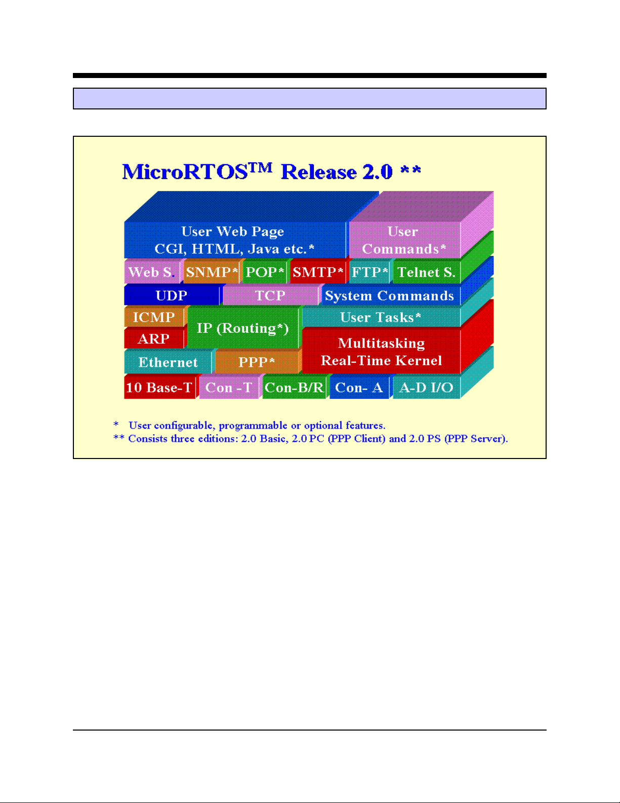
MicroRT OS™ V ersion 2.0 Diagram
The Slim-Link® Server operates with MicroRT OS™, Multi-User, Multi-T ask Real-T ime Operating System. This operating
system permits the Slim-Link Server to support multiple users and to run multiple tasks simultaneously in real-time.
Multiple users can be connected to either serial port or over the ethernet connection to the HTTP server.
MicroR TOS™ includes a preemptive real-time kernel to permit simultaneous support of multiple tasks. Up to 64 tasks
can be managed. The tasks are juggled based on their assigned priority level.
MicroR TOS™ handles network communications through the TCP/IP stack and Ethernet link. Both Ethernet’ s datalink
and physical layers are contained within the Slim-Link® Server module. The TCP/IP stack includes the Transport
Control Protocol, Internet Protocol, User Datagram Protocol, Internet Control Message Protocol, and Address Resolution
Protocol. In the future additional protocols will be added to the TCP/IP stack.
Descriptions of the operating system commands appear on the following page. Only the first 3 letters of each command
need to be entered and the commands are not case sensitive. Each command is terminated by striking the “Enter” key.
Advanced W eb Communication (15) Slim-Link® Server

MicroRTOS™ COMMANDS
Command Format Description
? ? Causes the Slim-Link® Server to list the operating system commands
Adduser ADD<cr> Allows the Root user to create a new user account
ARP ARP<cr> Causes the Slim-Link® Server to list the last 10 IP and Ethernet addresses
Buffer BUF<cr> Checks the data bufer usage and permits selective clearing of the data buffer .
This command can only be executed by the Root user.
Deluser D EL<cr> Allows the Root user to delete an existing user account
Dir DIR<cr> Causes the Slim-Link® Server to list all of the files in both SRAM and Flash
memory . It also shows the total amount of memory used for these files.
Erase ERA[file]<cr> Marks the listed file as erased although the file remains resident in Flash
Memory until the memory sector is erased. This command can only be executed
by the Root user.
Exit EXI<cr> Causes the Slim-Link® Server to exit operating system and return to the XE186
Monitor .
Host HOS<cr> Causes the Slim-Link® Server to list the latest IP host sites visited
Level LEV <cr> Allows the Root user to check command security levels and make alterations
as required.
Login LOG<cr> Allows a user to log into the system
Password PAS<cr> Allows the user to change their password. A Root user may change any
users password.
Ping PIN [IP Address] <cr> Causes the Slim-Link® Server to send out a test call to the listed IP Address
and report on the successful response.
PPP PPP<cr> In the PPP Client Edition this command causes the Slim-Link® Server to
display the loaded ISP parameters.
Reboot REB<cr> Allows the Root user to initialize a system reboot.
Resume RES[priority]<cr> Allows the Root user to resume a suspended task.
SetIP SET<cr> A l lo w s t he u s e r to r ead, and if desired change, the Slim-Link® Server’s IP
configuration.
Shutdown SHU<cr> Initiate a shutdown of MicroRTOS. This command can only be executed by
a Root user from Console_A.
Status STA<cr> Causes the Slim-Link® Server to report on the status of the operating system,
HTTP Server, and Serial Ports.
Stop STO[priority]<cr> Allows the Root user to Suspend the the listed task.
Task T AS<cr> Causes the Slim-Link® Server to list the tasks currently in memory . The list
includes the assigned priority and size of each task.
Telnet Tel[on/off]<cr> Allows the Root User to select or deselect the T elnet Server Function.
Time TIM<cr> Causes the Slim-Link® Server to report the date and time stored in the on
board real-time clock and permits the user to set a new date and time. This
command is only supported by the A WC86A module.
User USE<cr> Displays the user list and allows the Root user to change user priority levels.
V ersion VER<cr> Displays the MicroR T OS V ersion level
Web WEB[ON/OFF/Status]<cr> Controls the Web Server status of the Slim-Link® Server. This command can
only be executed by a Root user
<TAB> <tab> Striking the TAB key causes the Slim-Link® Server to re-execute the last
operating system command.
Advanced W eb Communication (16) Slim-Link® Server

Slim-Link® Server Debug Utility Commands
A Debug utility can be loaded in the Slim-Link Server’s Flash memory . This Debug program permits the developer to
exercise Flash Memory, the Real-Time Clock, Analog to Digital Convertor, and Digital to Analog Convertor through
either of the Slim-Link® Server’s serial ports. The file debug.cmd must be loaded into the MicroRT OS system subdirectory
in the Slim-Link Server’s Flash memory . The Debug Utility provides the commands listed below. These commands must
be issued in ten-bit character format (8 data bits, no parity) at 38,400 bits per second.
Command Format Description
A/D A/D Read the values on each of the 8-Channels of the Analog to
Digital Convertor. This command is available only on the
AWC86A.
C C [Start Addr, End Addr] Compare listed Memory Locations
D D [Start Addr, End Addr] Display contents of memory in the selected range
D/A D/A Convert Digital Inputs to Analog V alue. This command is avail-
able only on the AWC86A.
E E [Start Addr, List new values] Enter new values beginning with selected memory address.
F F [(Start Addr, End Addr), Fill Memory Range with Listed values
List new values]
H H Help! List Monitor Commands
I I[Word] Input Word
M M [(Start Addr, End Addr), Move data in memory range to new location beginning with
New Addr] New Memory Address
O O[Word] Output Word
Q Q Quit MicroRTOS™ Debug utility and Return to MicroR T OS™
S S [(Start Addr, End Addr), Search range of addresses for listed value
List V alue]
Advanced W eb Communication (17) Slim-Link® Server

Slim-Link® Server HTTP Server
The Slim-Link® Server includes an HTTP Server to support user web pages. The Slim-Link® HTTP Server is compatible
with all currently popular W eb Browsers including Internet Explorer and Netscape. The Slim-Link® HTTP server can
dynamically create W eb pages using the Common Gateway Interface(CGI) to show system status or process data.
A sample web page is included in the Slim-Link® Server embedded firmware. Developers can modify the firmware to
quickly develop a Web Page to suit their application.
Slim-Link® Server TCP/IP Stack
The Slim-Link® Server includes an embedded TCP/IP Stack to support Internet Communications. This stack is
illustrated below using the OSI architechure model. TCP/IP includes four clearly defined layers; Application,
Transport, Network, and Data Link. The presentation and session layers have been bypassed by TCP/IP.
Layer Definition Embedded in Slim-Link® Server
7 Application Web Server / Telnet Server / PPP / SMTP / SNMP
4 Transport TCP / UDP
3 Network IP / ICMP
2 Data Link ARP / Ethernet / PPP
1 Physical 10Base-T
Protocol Definition Description
TCP Transport Control Protocol The Transport Control Protocol provides the means to insure that
internet communications are reliable.
UDP User Datagram Protocol The User Datagram Protocol facilitates the communication from one
machine to another.
IP Internet Protocol The Internet Protocol performs three functions in internet
communications: It defines the format of all data. It performs routing
of the data through the network. I defines how hosts an routers should
process the data packets.
ICMP Internet Control Message The Internet Control Message Protocol allows routers on the internet
Protocol to report errors and unexpected occurrences.
ARP Address Resolution Protocol The Address Resolution Protocol increases internet efficiency by
binding together machine IP addresses.
PP P Point to Point Protocol Point ot Point Protocol permits the transport of datagrams over a point
to point link such a analog modem connection.
10Base-T IEEE 802.3 10Base-T Ethernet provides a 10 Mbps communications bus over a
twisted wire pair.
Advanced W eb Communication (18) Slim-Link® Server

Terms of Sale
Devices sold by the Advanced Web Communication Division of Xecom are covered by the warranty provisions
appearing in its Terms of Sale only. Advanced Web Communication™ makes no warranty, express, statutory,
implied, or by description regarding the information set forth herein, or regarding the freedom of the described
devices from patent infringement. Advanced Web Communication™ makes no warranty of merchantability or
fitness for any purposes. Advanced Web Communication™ reserves the right to discontinue production and change
specifications and prices at any time and without notice. This product is intended for use in normal commercial
applications. Applications requiring extended temperature range, unusual environmental requirements, or high
reliability applications, such as military, medical life-support or life-sustaining equipment, are specifically not
recommended without additional processing and authorization by Advanced Web Communication for such
application.
Advanced Web Communication assumes no responsibility for the use of any circuitry other than circuitry embodied
in an Advanced Web Communication product. No other circuits, patents, or licenses are implied.
Life Support Policy
Advanced Web Communication’s products are not authorized for use as Critical Components in Life Support Devices or Systems.
Life Support Devices or Systems are devices or systems which, (a) are intended for surgical implant into the body,
or (b) support or sustain life, and whose failure to perform, when properly used in accordance with instructions provided in the labeling, can be reasonably expected to result in significant injury to the user.
A Critical Component is any component of a life support device or system whose failure to perform can be reasonably expected to cause failure of the life support device or system, or to affect its safety or effectiveness.
Copyright, Advanced W eb Communication™ © 2001
While Advanced Web Communication™ has made every effort to ensure that the information presented here is accurate, Advanced Web Communication™ will not be liable for any damages arising from errors or omission of fact.
Advanced Web Communication™ reserves the right to modify specifications and/or prices without notice. Product
mentioned herein are used for identification purposes only and may be trademarks and/or registered trademarks of
their respective companies.
Advanced Web Communication Division of Xecom Inc.
374 Turquoise Street, Milpitas, CA. 95035
Ph: 408-945-6640 Fax: 408-942-1346
Email: info@xecom.com
Web Addr ess: www.xecom.com
Advanced W eb Communication (19) Slim-Link® Server
 Loading...