

Page 1

Xerox
Data
Systems
Reference
Manual
Page 2
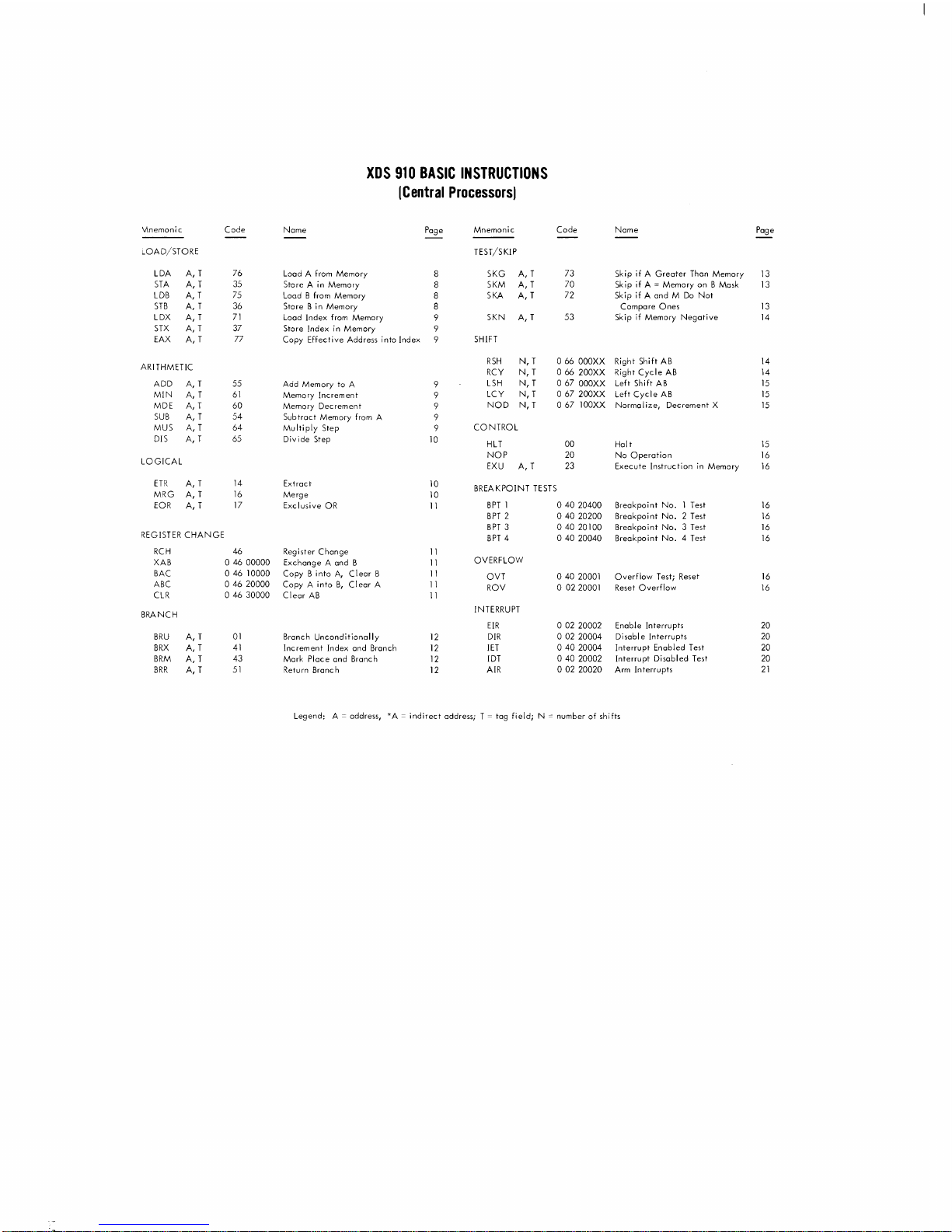
XDS
910
BASIC
INSTRUCTIONS
ICentral
Processorsj
Vlnemonic Code
Name
Page
Mnemonic Code Name
Page
LOAD/STORE
TEST/SKIP
LDA
A,
T
76
Load A
from
Memory
SKG
A,
T
73 Skip if A
Greater
Than Memory
13
STA
A,
T
35
Store A
in
Memory
SKM
A, T
70
Skip if A = Memory on B Mask
13
LDB
A,
T
75
Load B
from
Memory
SKA
A, T
72 Skip if A and M
Do
Not
STB
A,
T
36 Store B in Memory Compare
Ones
13
LDX
A, T
71
Load Index
from
Memory
SKN
A,
T
53 Skip if Memory
Negative
14
STX
A,
T 37
Store Index
in
Memory
EAX
A, T
77
Copy Effective Address into Index
SHIFT
ARITHMETIC
RSH
N, T
066
OOOXX
Right Shift
AB
14
RCY
N, T
066
200XX
Right
Cycle
AB
14
ADD
A,
T 55
Add
Memory to A
LSH
N, T
067
OOOXX
Left Shift
AB
15
MIN
A,
T
61
Memory Increment
LCY
N, T
067200XX
Left
Cycle
AB
15
MDE
A,
T 60
Memory Decrement
NOD
N, T
067
100XX Normalize, Decrement X
15
SUB
A,
T
54
Subtract Memory
from
A
MUS
A,
T 64
Multiply Step
CONTROL
DIS
A,
T 65 Divide Step
10
HLT
00 Halt
15
NOP
20 No
Operation
16
LOGICAL
EXU
A, T 23 Execute Instruction
in
Memory
16
ETR
A,
T
14
Extract
10
BREA
KPOINT
TESTS
MRG A, T
16
Merge
10
EOR
A,
T
17
Exclusive
OR
11
BPT
1
04020400
Breakpoint No. 1 Test
16
BPT
2
04020200
Breakpoint
No.2
Test
16
BPT
3
04020100
Breakpoint
No.3
Test
16
REGISTER
CHANGE
BPT
4
04020040
Breakpoint
No.4
Test
16
RCH
46
Register
Change
11
XAB
04600000
Exchange A and B
11
OVERFLOW
BAC
046
10000 Copy B into
A,
Clear
B
11
OVT
o 40 20001 Overflow Test; Reset
16
ABC
046
20000
Copy A into
B,
Clear
A
11
ROV
o 0220001 Reset Overflow
16
CLR
046
30000
Clear
AB
11
BRANCH
INTERRUPT
EIR
002
20002 Enable Interrupts 20
BRU
A,
T
01
Branch Unconditionally
12
DIR
00220004
Di
sabl e Interrupts 20
BRX
A,
T
41
Increment Index and Branch
12
lET
04020004
Interrupt Enabled Test
20
BRM
A, T 43 Mark Place and Branch
12
!DT
040
20002
Interrupt Disabled Test
20
BRR
A,
T
51
Retu
rn
Bronc
h
12
AIR
002
20020
Arm
Interrupts
21
Legend: A = address,
*A = indirect
address; T = tag field; N = number
of
shifts
Page 3
Price: $3.25
XOS
910
COMPUTER
REFERENCE
90
00
080
February 1970
MANUAL
Xerox
:91963-1970,
Data
Systems/70i
Xerox
Data
Systems,
Inc
South
Aviation Bouievard/Ei Segundo, Caiifornia 90245
Printed
in
U.S.A
Page 4
This
publication,
Manual,
cated
by a vertical
90
00
90
08C,
00
dated
line
08D,
in
the
is a minor
April
1966.
margin
REVISION
revision
Changes
of
the
of
to
affected
the XDS
the
page.
910
previous
Computer
edition
Reference
are
indi-
Title
XDS SYMBOL
XDS MONARCH Reference
XDS
910/925
XDS
910/920
Manual
XDS FORTRAN II Reference
XDS
900
XDS
ALGOL
XDS
Project
XDS Business Language
XDS
Sort/Merge
XDS
900 Series
and
META-SYMBOL
Programmed
Computer EXAMINER
Series
FORTRAN II
60
Reference
Management
Reference
Reference Manual
Utility
and Debug
Operators
System
RELATED
Reference
Manual
Technical
Diagnostic
Manual
Operations
Manual
Reference
Manual
Package
PUBLICATIONS
Manual
Manual
System
Manual
Manual
(AID)
Technical
Publication
90
05 06
900566
90 00 18
90
00 19
90
00 03
9005
87
90 06 99
90
08 18
90
1022
9009
01
20
No.
97
13
ii
Page 5
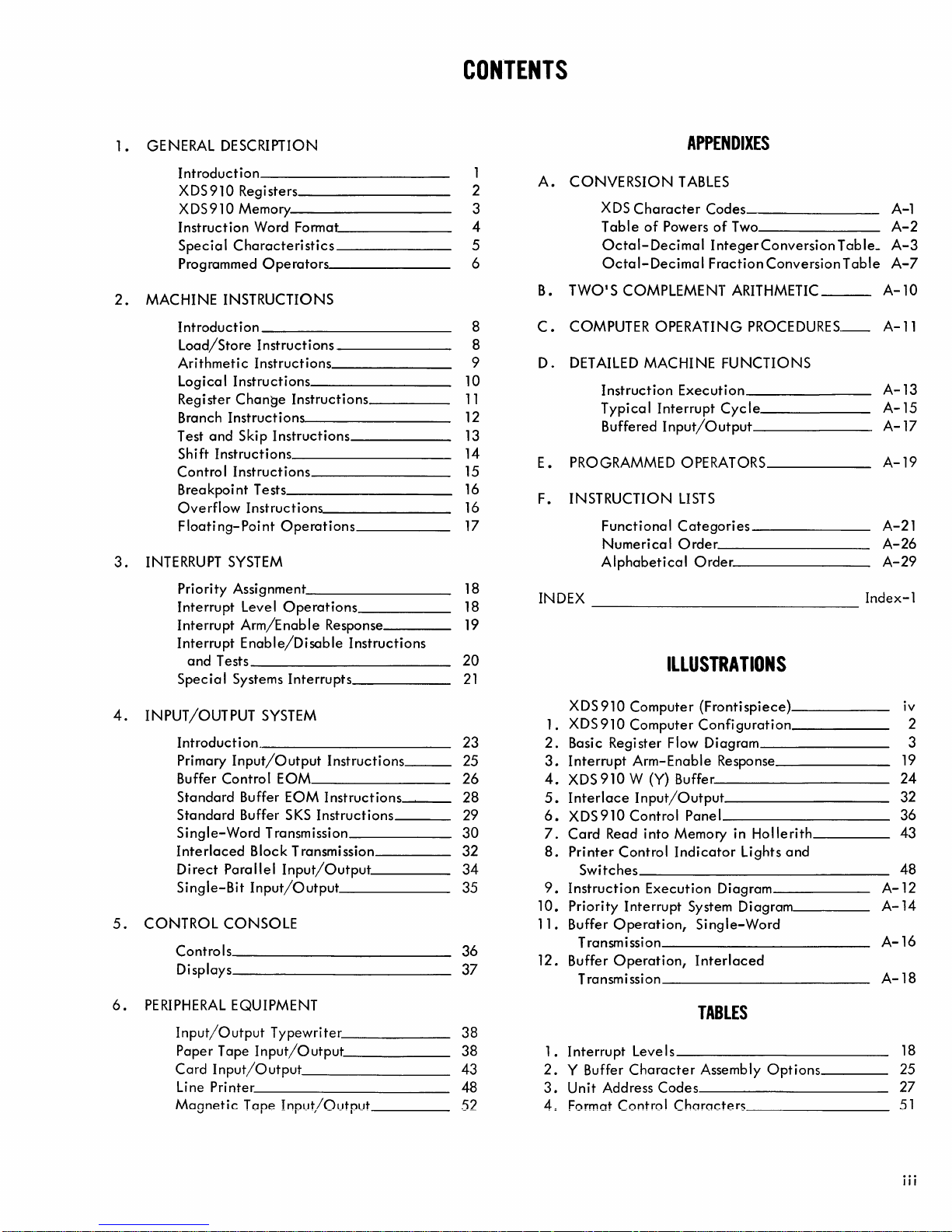
CONTENTS
GENERAL DESCRIPTION
1.
Introduction
XDS910
XDS910
Instruction
Specia I Characteristics
Programmed
MACHINE INSTRUCTIONS
2.
Introduction
Load/Store
Arithmetic
Logical
Regi
Branch
Test
Shift
Contro I Instructions
Breakpoint
Overflow
Floating-Point
INTERRUPT SYSTEM
3.
Priority
Interrupt
Interrupt
Interrupt
and
Special
Registers
Memory
Word Format
Instructions
Instructions
Instructions
ster
Change
Instructions
and
Skip
Instructions
Tests 16
Instructions
Assignment 18
Level
Arm/Enable
Enable/Disable
Tests
Systems
Operators
Instructions
Instructions
Operations
Operations
Interrupts
Response
Instructions
10
11
12
13
14
15
16
17
18
19
20
21
APPENDIXES
1
2
3
4
5
6
8
8
9
A.
CONVERSION
XDS
Table
Octal-Decimal
Octal-Decimal
B.
TWO'S
COMPUTER
C.
D.
DETAILED MACHINE
PROGRAMMED OPERATORS
E.
INSTRUCTION
F.
INDEX
COMPLEMENT ARITHMETIC
Instruction
Typical
Buffered
Functional
Numerical
Alphabetical
TABLES
Character
of
Powers
OPERATING
Execution
Interrupt
Input/Output
LISTS
Categories
Order
Codes
of
Two
IntegerConversion
Fraction
Order.
Conversion
PROCEDURES_
FUNCTIONS
Cycle
Table_
Table
Index-1
A-1
A-2
A-3
A-7
A-10
A-11
A-13
A-15
A-17
A-19
A-21
A-26
A-29
ILLUSTRATIONS
4.
INPUT/OUTPUT
Introduction.
Primary
Buffer
Standard
Standard
Single-Word
Interlaced
Direct
Single-Bit
CONTROL
5.
Controls
Displays
6.
PERIPHERAL
Input/Output
Paper
Card
li
Moanetic
Input/Output
Control
Parallel
CONSOLE
EQUIPMENT
Tape
Input/Output
ne Pri
nter
v
SYSTEM
Instructions
EOM
Buffer
EOM
Instructions
Buffer SKS
Transmission
Block Transmission
Input/Output
Input/Output
Tone T
• - 1- . -
Instructions
Input/Output
Typewriter
nnut/Outnut
'.---,
- - - 1- - -
___
23
25
26
28
29
30
32
34
35
36
37
38
38
43
48
52
XDS910
XDS
l.
Basic Register Flow Diagram 3
2.
Interrupt
3.
XDS
4.
Interlace
5.
6.
XDS910Controi
Card
7.
8.
Printer
Switches
9.
Instruction
10.
Priority
Buffer
1l.
Transmission
12.
Buffer
Transmission
Computer
910
Computer
Arm-Enable
910
W (Y) Buffer.
Input/Output
Read
into
Control
Interrupt
Operation,
Operation,
(Frontispiece)
Configuration
Panel
Memory in
Indicator
Execution
System Diagram
Single-Word
Interlaced
Response
Hollerith
lights
Diagram
and
TABLES
I
nte
l.
2.
3.
4=
rru pt Leve I s
Y Buffer
Unit
Address
Format
Character
Codes
Control
Assembly
Characters
Options
iv
2
19
24
32
36
43
48
A-12
A-14
A-16
A-18
18
25
27
51
iii
Page 6

XDS
910
Computer
iv
Page 7
1.
GENERAL
DESCRIPTION
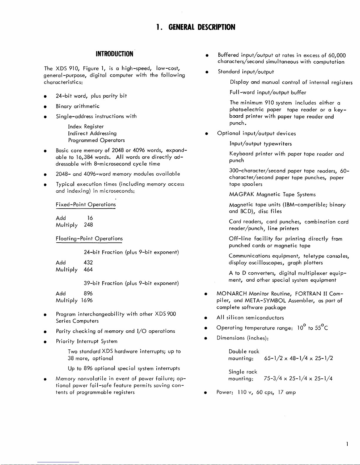
INTRODUCTION
The XDS 910, Figure 1,
general-purpose,
characteristi
24-bit
•
Bi
•
nary
Single-address
•
Index Register
Indirect
Programmed
• Basic
•
• Typical
core
able
to
dressable
2048-
and
indexing)
Fixed-Point
Add
Multiply
digital
cs:
word, plus
arithmetic
instructions
Addressing
memory
16,384
and
execution
words. All words
with
8-microsecond
4096-word
in microseconds:
Operations
16
248
Operators
is a high-speed,
computer
parity
bit
with
of
2048
or
4096
cycle
memory modules
times
(including
with
are
low-cost,
the
following
words,
di
rectly
time
available
memory
expand-
ad-
access
Buffered
•
characters/second
Standard
•
Display
Full-word
The minimum
photoelectric
board
punch.
Optional
•
Input/output
Keyboard pri
punch
300-character/second
character/second
tape
MAGPAK
Magnetic
and
Card
reader/punch,
input/output
simultaneous
input/output
and
manual
input/output
910
printer
input/output
spoo I ers
BC
readers,
with
typewriters
nter
Magnetic
tape
D), disc
card
at
rates
control
buffer
system
paper
units
line
tape
paper
devices
with
paper
paper
paper
tape
Tape Systems
(IBM-compatible;
fi
les
punches,
printers
in
excess
with
of
internal
includes
reader
tape
reader
tape
tape
punches,
combination
of
60,000
computation
registers
either
reader
readers,
a
or a key-
and
and
paper
binary
card
60-
Floating-Point
Add
Multiply
Add 896
Multiply
Program
•
Series Computers
Parity
•
Priority
•
Two
38
Up
Memory
•
tional
tents
of programmable registers
Operations
24-bit
432
464
39-bit
1696
interchangeability
checking
Interrupt
standard
more,
to 896
nonvolatile
power
Fraction
Fraction
of
memory
System
XDS
optional
optional
fail-safe
hardware
special
in
event
feature
(plus
(plus
with
and
of
9-bit
9-bit
other
I/O
operations
interrupts;
system
power
permits
exponent)
exponent)
XDS 900
up to
interrupts
failure;
saving
con-
op-
Off-line
punched
Communications
display
A to D
ment,
MONARCH
•
pi I
er,
and
complete
All
•
•
•
•
silicon
O
Dimensions (inches):
Power:
. t 100 to
peratmg
Doubl e
mounting:
Single
mounting:
110v,
facility
cards
osci 1I0scopes,
converters,
and
other
Monitor
META-SYMBOL Assembl
software
semiconductors
emperature
rack
rack
60
for
printing
or
magnetic
equi
pment, tel
graph
digital
special
Routine, FORTRAN
package
65-1/2 x 48-1/4 x 25-1/2
75-3/4 x 25-1/4 x 25-1/4
cps,
range:
17
amp
system
directly
tape
etype
plotters
multiplexer
equipment
er,
as
0
55
from
consol es,
equip-
II
Com-
part
of
C
Page 8
Up
to
896
special
I I I I
I I I I I I , , I I I
I I I I I I I I I : I
system
interrupts
Items with
dotted
lines
are
optional.
Single-Bit
and
Sense
Word
Parallel
(24 lines) .....
Buffer
Interrupt
Character
(6
bits,
plus
Buffer
parity)
XDS
The
910
Central
control
the
The A,
are
ison,
The
metic
The
register.
doubl
The
address
least
provide
The
memory address
time
wise
registers.
programmer
REGISTERS AVAILABLE TO
B,
available
test,
24-bit A register
operations.
24-bit B register
e-prec
24-bit X register
modification.
significant
an
14-bit P register
the
instruction
specified
Processor
Four
and
four
X,
and P registers
to
the
branch,
It
contains
i sion numbers.
indexing
by
bits
of
and
an
is
the
programmer for
(address
capability
Control
to
Device
910
of
are
program
is
the
is used as an
the
is used to
Indexing
(Program
instruction
being
program (with a
---l
.....
I/O
I/O
---
...
~~~,-----~~--~
Lines
----------------~
Full-word
I/O
33
(24 bits)
W Buffer
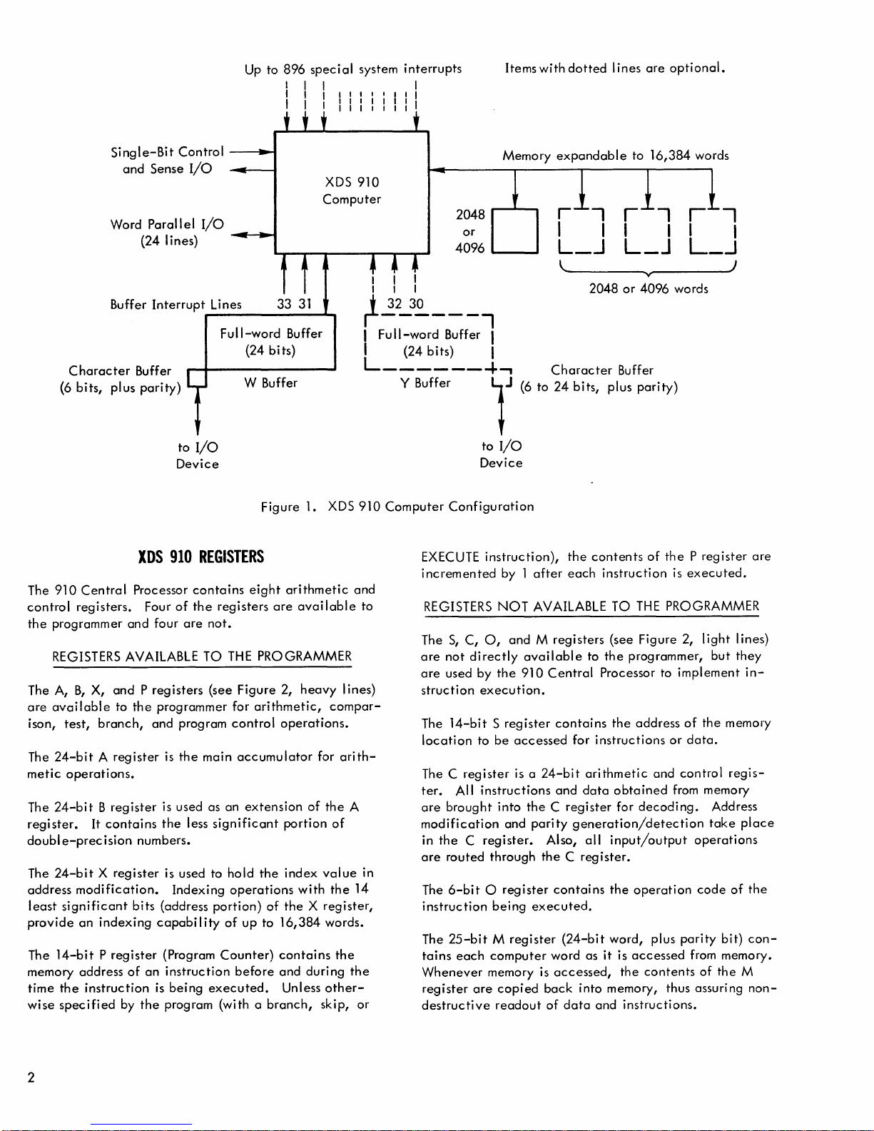
Figure 1.
XDS
Computer
31
Buffer
XDS
REGISTERS
contains
the
main
less
eight
registers
not.
THE
(see Figure 2,
significant
hold
operations
portion)
of
Counter)
executed.
are
PROGRAMMER
arithmetic,
control
accumulator
before
operations.
extension
the
of
up
to
16,384
contains
and
Unless
branch,
arithmetic
available
heavy
lines)
compar-
for
arith-
of
the
portion
index
the X register,
with
during
skip, or
of
value
the
words.
the
other-
910
2048
4096
I I
I I I
~2~~
I
Full-word
___
Buffer I
I (24 bits) I
L------4-,
Y Buffer
910
Computer
and
to
A
in
14
the
Configuration
EXECUTE
incremented
REGISTERS
The
S,
are
not
are
used by
struction
The
14-bit S register
location
The C
ter.
All
are
brought
modification
in
the C register.
are
routed
The
6-bit 0 register
instruction
The
25-bit M register
tains
each
Whenever
register
destructive
Memory
or
__
..,
lJ
to
I/O
Device
instruction),
by 1
NOT
C,
0,
directly
the
execution.
to
be
register
instructions
into
and
through
being
computer
memory is
are
copied
readout
expandable
_
l~--------_v~--------~)
2048
Character
(6 to
24
bits,
the
contents
after
each
AVAILABLE TO
and M registers
available
910
accessed
is a 24-bit
the C register
parity
the C register.
executed.
back
to
Central
contains
for
instructions
arithmetic
and
data
generation/detection
Also,
all
contains
(24-bit
word as
accessed,
into memory, thus assuring
of
data
and
to
16,384
or
4096
Buffer
plus
parity)
of
the P register
instruction
THE
PROGRAMMER
(see Figure 2,
the
programmer,
Processor to
the
address
and
obtained
for
decoding.
input/output
the
operation
word, plus
it
is
accessed
the
contents
instructions.
words
r
-,
I I
L_..J
words
is
executed.
light
but
implement
of
the
memory
or
data.
control
from memory
parity
regis-
Address
take
operations
code
of
bit)
from memory.
of
the
are
lines)
they
in-
place
the
con-
M
non-
2
Page 9
A
(Main
Accumulator)
(Ins
P
(Program
S
Register
(Memory
Register
0
Reg.
true
tion)
Register
Counter)
Address)
B
Register
(Extended
1
.
C
Register
(Arithmetic
-----------------~
Accumulator)
II
and
Control)
X
Register
(Index)
•
,
M
~
Register
(Memory
Memory
Access)
The
basic
2048-
or
size
of
24
word
memory
cessor
and
all
memory.
octal
location
through
memory),
memory
memory
An
available
into
eration,
ecuted.
termine
is
Before
the
can
loss,
be
transient
The
checks
07777
in a 16K
where
attempt
such a location
the
operating.
accessing a memory
power
be
successfu
the
inc I uded
computer
for
XDS
910
4096-word
bits,
plus
modules
the
input/output
Addresses
00000
(4K
or
00000
the
to
read
causes
with
the
Thus, a
memory
to
ensure
Ily
computer
that
power
failure
automatically
it
during
XDS
910
memory
magnetic
parity.
are
through
memory),
through
system
next
from a
zeros
to
essentially
next
instruction
program
size
that
compl
halts.
prevents
or
each
MEMORY
consists
core
Additional
available.
buffers
for
memory
03777
00000
37777
is a
IIwrap-aroundli
location
location
be
read.
can
use
of
the
word,
the
entire
eted.
Special
loss
of
manual
generates
read/write
Figure
of
one
module
The
can
directly
words
(2K
through
(16K
memory).
after
37777
whose
An
attempt
results
machine
in a IIno-opli
in
sequence
this
property
the
computer
read/write
If
it
detects a power
logic
information
power
even
cycle.
2.
random
with a word
2048-
or
Central
extend
memory),
17777
or
circular
is
00000.
address
to
being
to
within
shutoff.
which
checks
cycle
(optional)
due
pari
ty
Setting
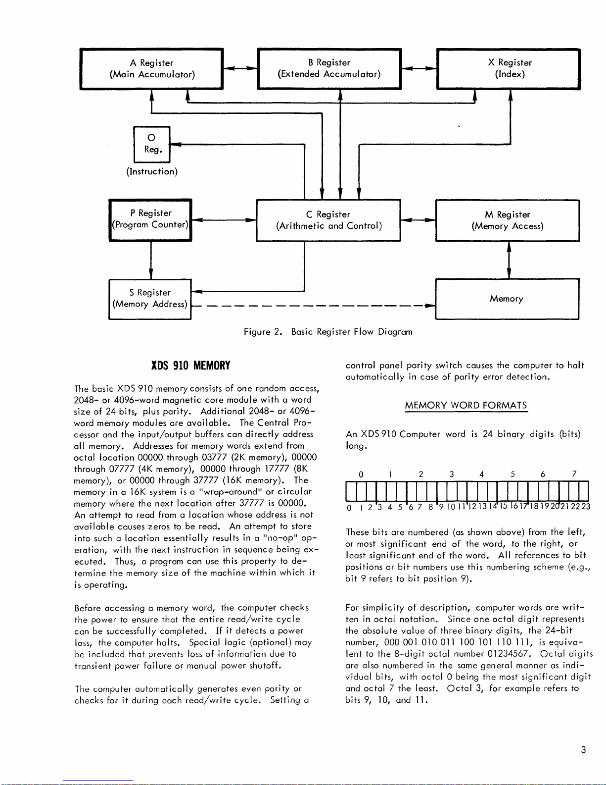
Basic
access,
4096-
Pro-
address
from
00000
(8K
The
is
not
store
op-
ex-
de-
may
to
or
a
Register
it
Flow
Diagram
control
automatically
An XDS
long.
panel
910
pari
ty
in
case
MEMORY
Computer
swi
of
tch
parity
WORD
word
causes
error
FORMATS
is
24
the
computer
detection.
binary
digits
o I 2 3 4 5 6 7
IIIIIIIIIIIIIIIIIIJ
o
123
4 5
67 8 9101112131415161
These
bits
are
or
most
significant
least
significant
positions
bit 9 refers
For
ten
the
number,
lent
are
vidual
and
bits
or
simplicity
in
octal
absolute
000001010011100101110111,
to
the
also
numbered
bits,
octal 7 the
9,
10,
numbered
bit
numbers
to
bit
of
notation.
value
8-digit
with
least.
and
11.
end
description,
octal 0 being
end
of
the
position
Since
of
three
octal
in
the
Octal
(as
shown
of
the
word.
use
this
9).
binary
number
same
above)
word,
All
numbering
computer
one
octal
digits,
01234567.
general
the
most
3,
for
example
II
18192
from
to
the
references
scheme
words
digit
the
is
Octal
manner
significant
to
hal
(bits)
Jill
212223
the
left,
right,
or
to
(e.g.,
are
writ-
represents
24-bit
equiva-
digits
as
indi-
digit
refers
to
t
bit
3
Page 10
The
computer
012
Bit
position
coding
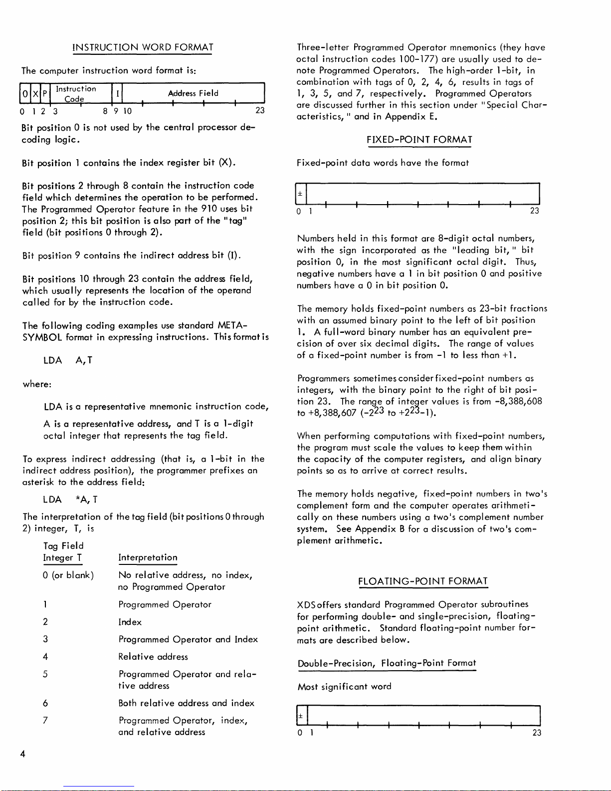
INSTRUCTION WORD FORMAT
3
instruction
0 is
not
word format is:
8910
used
by
the
Address
centra
logic.
I I
I processor
Field
de-
23
Three-I
octal
note
etter
instruction
Programmed
combination
1,
3,
5,
and
are
discussed
acteristics,
Programmed
codes
Operators.
with tags
7,
respectively.
further
II
and in
FIXED-POINT
Operator
100-177)
of
0, 2, 4, 6, results in tags
mnemonics (they
are
usually used to
The
high-order
Programmed
in this
Appendix
section
E.
under
FORMAT
1-bit,
Operators
"Special
have
dein
of
Char-
Bit
position 1 contains
Bit positions 2 through 8
field
which
determines
The Programmed
position
field
Bit position 9
2;
this
bit
(bit
positions 0 through
contains
Bit positions 10 through
which
usually
called
for by
The following
represents
the
coding
the
contain
the
Operator
position
the
23
the
instruction
examples
index
operation
feature
is a
indirect
contain
SYMBOL format in expressing
LDA
A,
T
where:
LDA
is a
representative
A is a
octal
To
express
indirect
address
asterisk to
LDA
interpretation
The
2)
integer,
representative
integer
that
indirect
position),
the
address
*A, T
of
T,
is
address,
represents
addressing
the
field:
the
tag
Tag Field
Integer
T
Interpretation
register
the
in
Iso
bit
instruction
to
be
the
910
part
of
performed.
the
2).
address
the
location
address
of
the
bit
code.
use
standard
instructions.
mnemonic
This format is
instruction
and T is a 1-digit
the
tag
field.
(that
is, a
1-bit
programmer
field
(bit positions 0 through
prefixes
(X).
code
uses
bit
II
tag"
(I).
fie Id,
operand
META-
in
code,
the
an
Fixed-point
data
o 1
Numbers
with
position
negative
numbers
The memory holds
with
1. A
cision
of a fixed-point
Programmers
integers,
tion
to
When performing
the
the
points
The memory holds
complement
cally
system.
plement
held
the
sign
0, in
numbers
have
an
assumed
full-word
of
over
sometimesconsiderfixed-point
with
23.
The
+8,388,607
program must
capacity
so
as to
form
on
these
See
arithmetic.
in this format
incorporated
the
a 0 in
six
the
range
(-2
of
arrive
numbers using a
Appendix
words
have
the
format
are
8-digit
as
the
"Ieading
most
have
a 1 in
bit
fixed-point
binary
binary
point
number has
decimal
significant
position
digits.
octal
bit
position 0 and
O.
numbers as
to
the
left
an
equivalent
The
number is from -1 to less
binary
23
computations
scale
the
negative;
and
point
of
integer
to +223_1).
the
values
computer
at
correct
fixed-point
the
computer
to
the
right
values
with
is
fixed-point
to
keep
registers, and
results.
operates
two's
complement
B for a discussion
octal
bit,
digit.
23-bit
of
bit
range
of
than
numbers as
of
from
-8,388,608
them
align
numbers in
arithmeti-
of
two's
numbers,
II
bit
Thus,
positive
fractions
position
pre-
values
+ 1.
bit
posi-
numbers,
within
binary
two's
number
com-
23
o (or
blank)
2
3
4
5
6
7
No
relative
address, no
no Programmed
Programmed
Operator
Index
Programmed
Relative
Programmed
tive
address
Both
relative
Programmed
and
relative
Operator
address
Operator
Operator,
address
Operator
address
4
index,
and Index
and
rela-
and
index
index,
FLOA
XDS
offers
standard
for performing
point
arithmetic.
mats
are
double-
described
Double-Precision,
Most
significant
o 1
lING-POINT
Programmed
and
Standard
below.
Floating-Point
word
FORMAT
Operator
subrouti nes
single-precision,
floating-point
Format
floating-
number
for-
23
Page 11
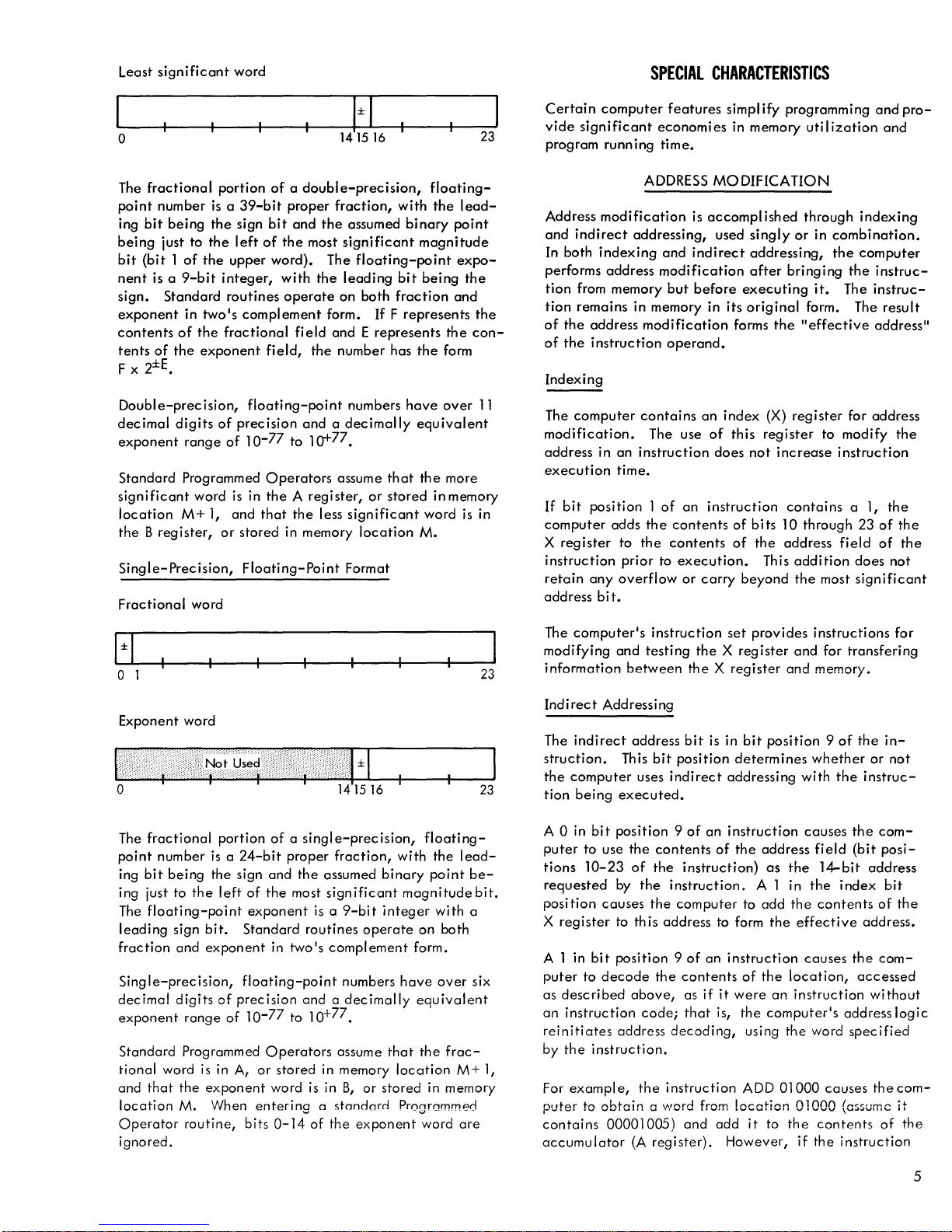
Least
significant
word
SPECIAL
CHARACTERISTICS
o
The
fractional
point
number
ing
bit
being
just
bit
(bit 1 of
nent
is a
sign.
Standard
exponent
contents
tents
of
x 2±E.
F
Double-precision,
decimal
exponent
Standard
significant
location
the B register,
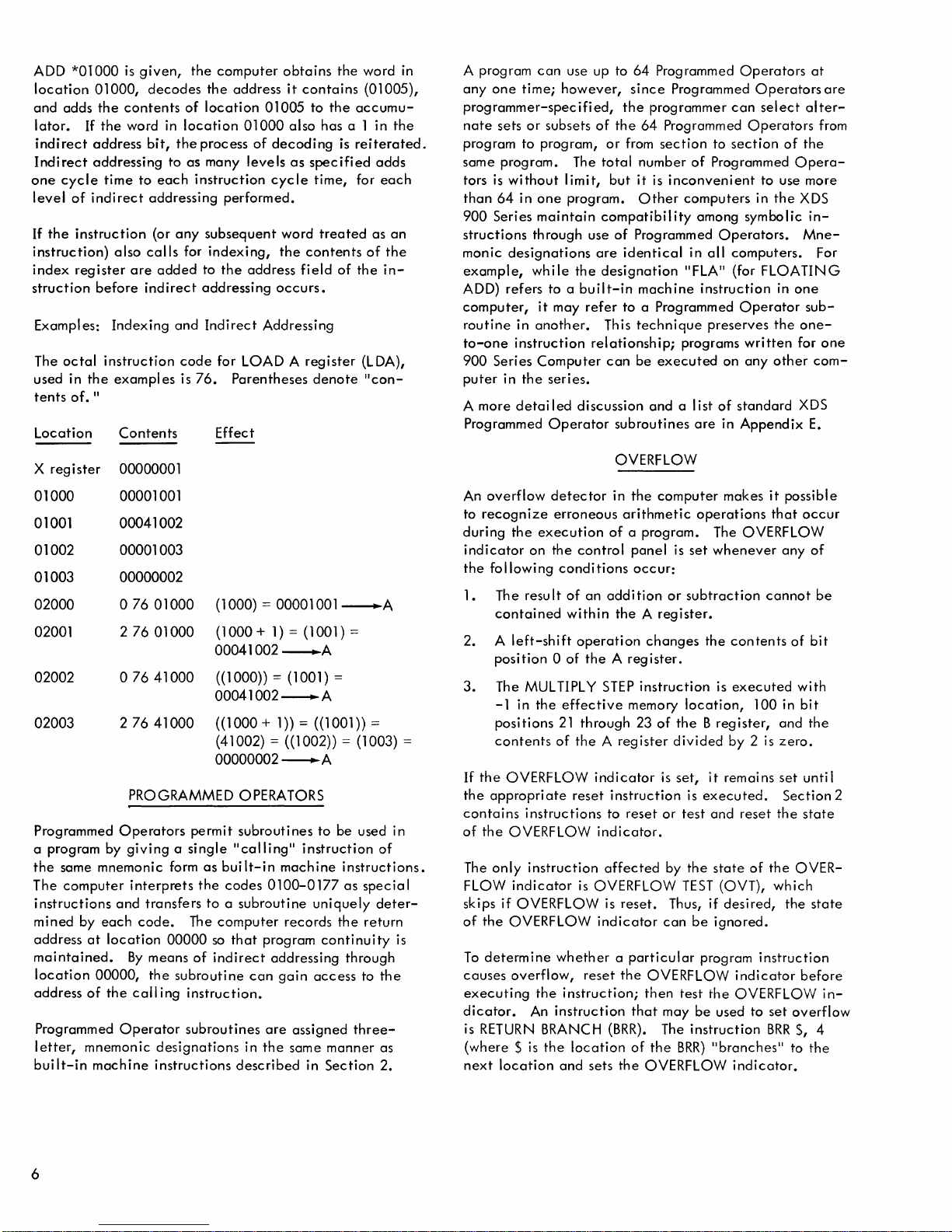
Single-Precision,
Fractional
is a 39-bit
being
the
to
the
the
9-bit
in
two's
of
the
the
exponent
digits
of
range
Programmed
word
M+
1,
word
portion
sign
left
of
upper
integer,
routines
complement
fractional
field,
floating-point
precision
of
10-
Operators
is
in
the A register,
and
that
or
stored
Floating-Poi
141516
of a double-precision,
proper
bit
and
the
the
most
word).
with
77
The
the
operate
form.
fi
eld
and E represents
the
and a decimally
to
10+77•
the
less
in memory
nt
fraction,
assumed
significant
leading
on
number
numbers
assume
significant
Format
with
floating-point
bit
both
fraction
If
F
has
that
or
stored
location
floating-
the
binary
represents
have
point
magnitude
expo-
being
and
the
the
form
over
equivalent
the
more
in memory
word
M.
lead-
the
the
con-
is in
23
11
Certain
vide
program
Address
and
In
performs
tion
tion
of
of
Indexing
The
modification.
address
execution
If
computer
X
instruction
retain
address
computer
significant
running
modification
indirect
both
indexing
address
from
remains
the
address
the
instruction
computer
in
bit
position 1 of
register
any
bi
memory
an
time.
adds
t.
economi
time.
ADDRESS
addressing,
and
modification
in
memory
modification
contains
The
instruction
the
to
the
prior
to
overflow
features
es
MODIFICATION
is
accomplished
used
indirect
but
before
in
operand.
an
use
of
does
an
instruction
contents
contents
execution.
or
carry
simplify
in
memory
singly
addressing,
after
executing
its
original
forms
index
this
register
not
of
bits
of
the
This
beyond
programming
uti I ization
through
or
in
bringing
it.
form. The
the
"effective
(X)
register
increase
contains
10
through
address
addition
the
and
indexing
combination.
the
computer
the
instruc-
The
instruc-
address"
for
address
to
modify
instruction
a 1,
23
of
field
of
does
most
significant
pro-
and
result
the
the
the
the
not
" 1
v I
Exponent
word
o
The
fractional
point
number
ing
bit
ing just
The
floating-point
leading
fraction
Single-precision,
decimal
exponent
Standard
tional
word
and
that
location
Operator
ignored.
is a 24-bit
being
the
to
the
sign
bit.
and
exponent
digits
range
Programmed
is
the
exponent
M. When
routine,
portion
sign
left
of
the
exponent
Standard
floating-point
of
precision
of
10-
Operators
in A,
or
enterina
bits
141516
of a single-precision,
proper
and
in
77
stored
word is in
0-14""
fraction,
the
assumed
most
significant
is a
9-bit
routines
two's
and a decimally
to 10+77•
of
operate
complement
numbers
assume
in memory
B,
or
a stcmcJrm1
the
ex~onen;:~;d··;r-e
.
binary
integer
that
stored
floating-
with
the
point
magnitude
with
on
both
form.
have
over
equivalent
the
frac-
location
in memory
Prnnrnmmpej
lead-
be-
a
M+
23
23
bit.
six
1,
The
computer's
modifying
information
Indirect
The
struction.
the
tion
A 0 in
puter
tions
requested
posi
X
A 1 in
puter
as
an
reinitiates
by
For
puter
contains
accumulator
Addressing
indirect
computer
being
bit
to
use
10-23
tion
causes
register
bit
to
decode
described
instruction
the
instruction.
example,
to
obtain
00001005)
instruction
and
testing
between
address
This
uses
executed.
position 9 of
the
of
by
the
to
this
position 9 of
above,
code;
address
the
(A
the X register
bit
bit
position
indirect
contents
the
instruction)
instruction.
the
computer
address
the
contents
as
that
decoding,
instruction
a
\AlOrd
and add
register).
set
provides
the X register
is in
bit
position 9 of
determines
addressing
an
instruction
of
the
address
as
A 1 in
to
add
to form
an
if
is,
from
it
the
instruction
of
the
were
an
the
computer's
using
ADD
location
it
to
However,
instructions
and
and
memory.
whether
with
causes
field
the
14-bit
the
the
contents
effective
causes
location,
instruction
the
word
01000
01000
the
contents
if
the
for
transfering
the
the
instruc-
the
(bit
index
address.
the
accessed
address
specified
causes
(assume
instruction
for
in-
or
not
com-
posi-
address
bit
of
the
com-
without
logic
the
com-
it
of
the
5
Page 12
ADD
*01000
location
and
lator.
indirect
Indirect
one
level
If
the
01000,
adds
If
address
addressing
cycle
of
indirect
instruction
instruction)
index
register
struction
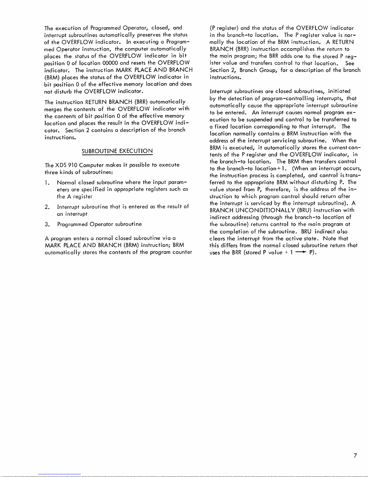
Exampl es:
The
octal
used in
tents
of.
the
"
Location
is
given,
decodes
the
contents
the
word in
bit,
time
to
addressing
also
calls
are
before
indirect
Indexing
instruction
examples
Contents
to
each
(or
any
added
and
the
computer
the
of
location
location
the
process
as
many
instruction
subsequent
for
indexing,
to
addressing
Indirect
code
for LOAD A
is
76.
Effect
address
01005
01000
of
decoding
levels
cycle
performed.
word
the
the
address
occurs.
Addressing
Parentheses
obtains
it
contains
to
also
has
as
specified
time,
treated
contents
field
register
denote
the
the
accumu-
a 1 in
is
reiterated.
for
of
the
word
in
(01005),
the
adds
each
as
an
of
the
in-
(L
DA),
"con-
A program
anyone
can
time;
use up to
however,
programmer-specified,
nate
sets
or
subsets
of
program to program,
same program. The
tors
is
without
than
64
900
Series
structions
monic
designations
example,
ADD) refers to a
computer,
routine
to-one
900
puter
A more
in
instruction
Series
in
detailed
Programmed
limit,
in
one
program.
maintain
through use
whi Ie
it
may
another.
Computer
the
series.
Operator
are
the
built-in
refer
relationship;
discussion
64
Programmed
since
Programmed
the
programmer
the
64
Programmed
or
from
section
total
number
but
it is
inconvenient
Other
compatibil
of
ity
Programmed
identical
designation
machine
to a Programmed
This
technique
can
be
executed
and
a list
subroutines
Operators
Operators
can
select
Operators
to
section
of
Programmed
to use more
computers
in
among symbolic
Operators.
in
all
computers.
"FLA"
(for FLOA TIN G
instruction
Operator
preserves
programs
are
written
on
any
of
standard
in
Appendix
of
Opera-
the
in
one
the
other
at
alter-
the
XDS
in-
Mne-
sub-
one-
for
com-
XDS
E.
are
from
For
one
X
register
01000
01001
01002
01003
02000
02001
02002
02003
00000001
00001001
00041002
00001003
00000002
076
276
07641000
27641000
PROGRAMMED OPERATORS
Programmed
a program by
the
some mnemonic form
The
computer
instructions
mined by
address
maintained.
location
address
Programmed
letter,
built-in
Operators
giving a single
interprets
and
each
at
location
By
00000,
of
the
Operator
mnemonic
machine
01000
01000
transfers
code.
00000
means
the
subroutine
call
ing
designations
instructions
(1000) = 00001001
( 1
000 + 1) = (1
00041002
( ( 1 000)) =
00041002~A
( ( 1
000
----.A
(1
+ 1)) =
001) =
001) =
((1
001 )) =
~A
(41002) = ((1002)) = (1003) =
00000002~A
permit
as
the
to a
The
of
so
indirect
subroutines
"calling"
built-in
codes
0100-0177
subroutine
computer
that
program
can
to be used in
instruction
machine
instructions.
as
uniquely
records
the
continuity
addressing through
gain
access
instruction.
subroutines
are
in
the
same
described
assigned
manner
in
Section
of
special
deter-
return
to
the
three-
as
2.
OVERFLOW
An
overflow
to
recognize
during
indicator
the
following
1. The
contained
2. A
position 0 of
3.
The MULTIPLY
-1 in
positions
contents
If
the
the
appropriate
contains
of
the
The
only
FLOW
skips
if
of
the
detector
erroneous
the
execution
on
the
control
conditions
result
of
within
left-shift
the
of
operation
effective
21
through 23
the
OVERFLOW
reset
instructions
OVERFLOW
instruction
indicator
is
OVERFLOW is
OVERFLOW
in
the
computer
arithmetic
of
a program. The OVERFLOW
panel
is
makes
operations
set
whenever
occur:
an
addition
or
subtraction
the A register.
changes
the
the A register.
STEP
instruction
memory
A reg
ister
indicator
instruction
to
reset
of
is
or
is
location,
the B register,
divided
set,
it
remains
is
executed.
test
and
indicator.
affected
OVERFLOW
indicator
reset.
by
the
TEST
Thus, if
can
be
state
(OVT),
desired,
ignored.
it
that
cannot
contents
executed
100 in
by 2 is
reset
of
the
which
possible
occur
any
of
of
bit
with
bit
and
the
zero.
set
untii
Section
the
state
OVER-
the
state
be
2
is
To
determine
causes
executing
dicator.
is
RETURN
(where $ is
next
location
whether a particular
overflow,
the
An
reset
instruction;
instruction
BRANCH
the
location
and
sets
the
then
that
(BRR).
of
the
OVERFLOW
program
OVERFLOW
test
the
may
be
used to
The
instruction
the
BRR)
"branches" to
instruction
indicator
before
OVERFLOW i
set
overflow
BRR
$, 4
the
indicator.
n-
6
Page 13
The
execution
interrupt
of
med
places
position a of
indicator.
(BRM)
bit
not
The
merges
the
location
cator.
instructions.
The XDS
three
1.
2.
3.
A program
MARK
automatically
subroutines
the
OVERFLOW
Operator
the
places
position a of
disturb
instruction
the
contents
and
Section 2 contains a description
910
kinds
Normal
eters
are
the A register
Interrupt
an
interrupt
Programmed
enters
PLACE
of
Programmed
automatically
indicator.
instruction,
status
of
the
location
The
the
the
OVERFLOW
contents
of
places
SUBROUTI·NE EXECUTION
Computer
of
subroutines:
closed
specified
subroutine
AND
stores
00000
instruction
status
the
effective
RETURN
of
bit
position a of
the
subroutine
Operator
a normal
BRANCH
the
Operator,
In
the
computer
OVERFLOW
and
MARK
of
the
OVERFLOW
memory
indicator.
BRANCH
the
OVERFLOW
the
result
in
makes
it
possible
where
in
appropriate
that
is
entered
subroutine
closed
(BRM)
contents
executing a Program-
resets
the
subroutine
of
closed,
preserves
automatically
indicator
the
PLACE
(BRR)
AND
location
automatically
indicator
effective
OVERFLOW
of
to
the
input
registers
as
instruction;
the
program
and
the
status
in
bit
OVERFLOW
BRANCH
indicator
memory
the
execute
the
via
and
with
indi-
branch
param-
such
result
a
BRM
counter
in
does
as
of
(P
register)
in
the
branch-to
mally
the
location
BRANCH
the
ister
Section
i
nstruc
Interrupt
by
automatically
to
be
ecution
a
fixed
location
address
BRM
tents
the
to
the
the
ferred
value
struction
the
BRANCH
indirect
the
the
clears
this
uses
(BRR)
main
program;
value
2, Branch
ti
ons.
subroutines
the
detection
entered.
to
be
location
normally
of
the
is
executed,
of
the P register
branch-to
branch-to
instruction
to
the
stored
to
interrupt
UNCONDITIONALLY
addressing
subroutine)
completion
the
interrupt
differs
the
BRR
and
the
status
location.
of
the
instruction
the
BRR
and
transfers
Group,
are
of
program-controlling
cause
the
An
interrupt
suspended
corresponding
contains a BRM
interrupt
it
automatically
and
location.
location
process
appropriate
from
P,
therefore,
which
program
is
serviced
(through
returns
of
the
subroutine.
from
from
the
norma I
(stored P value
of
the
The P
BRM
accompl
adds
control
for a
closed
appropriate
causes
and
control
servicing
the
OVERFLOW
The
BRM
+ 1. (When
is
completed,
BRM
without
control
by
the
the
control
the
to
active
closed
+ 1
OVERFLOW
register
instruction. A RETURN
ishes
one
to
to
that
description
subroutines,
interrupt
normal program
to
to
that
interrupt.
instruction
subroutine.
stores
then
an
and
disturbing
is
the
address
should
interrupt
(BRU)
branch-to
the
main
BRU
state.
subroutine
---..
P).
indicator
value
the
return
the
stored P reg-
location.
of
the
initiated
interrupts,
subroutine
be
transferred
with
When
the
current
indicator,
transfers
interrupt
control
of
return
subroutine).
instruction
location
program
indirect
Note
return
is
nor-
to
See
branch
that
ex-
The
the
the
con-
control
occurs,
is
trans-
P.
The
the
in-
after
with
of
at
also
that
that
to
in
A
7
Page 14
This
section
groups.
and
A-21,
A
companies
ing
identifies
ter
used
indicates
instruction,
cates
ory.
If
indexing
tion 9 of
addressing
instructions
field;
memory,
tion
The
criptions:
Lists
alphabetical
A-26,
diagram
each
diagram
X in
bit
with
that
bit
position 1 of
cannot
the
these
but
code
following
INTRODUCTION
describes
of
and
representing
the
description
the
instruction.
position 1 indicates
the
instruction,
that
indirect
and
the
instruction
instruction
cannot
are
instructions
use
of
the
statements
XDS
instructions
order
are
A-29
respectively.
the
is
the
mnemonic
addressing
the
letter
the
instruction
be
used with
diagram
be
used
shown
with
do
the
address
instruction.
apply
910
in
given
format
of
each
Within
the
letter
M in
obtains
the
with
octal
not
field
instructions
functional,
in
Appendix
of
the
instruction.
code
and
the
diagram,
that
indexing
I in
bit
can
be
the
address
an
operand
diagram
instruction;
contains
the
instruction.
numbers in
require
to
an
to
extend
the
instruction
2.
MACHINE
in
functional
numerical,
F,
pages
instruction
Preced-
name
that
the
can
be
position
used
with
the
field
indi-
from
mem-
contains a 0,
if
bit
a 0,
indirect
Some
the
address
operand
the
from
opera-
de-
ac-
let-
9
posi-
INSTRUCTIONS
The
interrupt
of
any
BRANCH
Instruction
where
required
Indexing
but
each
ditional
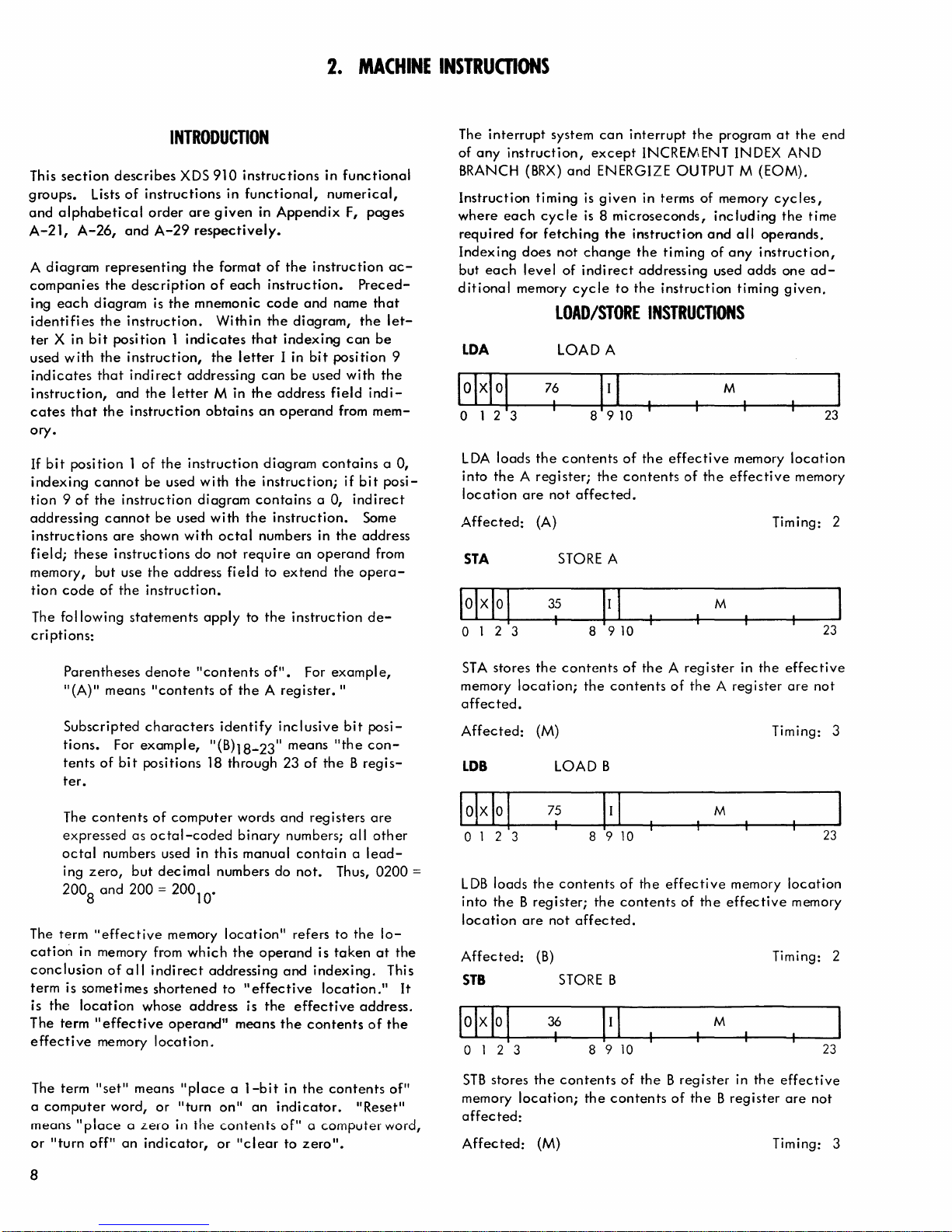
LOA
o 1 2 3
LOA
loads
into
the A register;
location
Affected:
STA
o 1 2 3
system
instruction,
(BRX)
timing
each
cycle
for
fetching
does
level
memory
except
and
is
is 8 microseconds,
not
change
of
indi
cycle
LOAD/STORE
LOAD A
76
I
the
contents
are
not
affected.
(A) Timing: 2
STORE A
8 9
can
interrupt
INCREMENT INDEX
ENERGIZE OUTPUT M (EOM).
given
in terms of memory
the
instruction
the
rect
addressing
to
the
the
program
including
and
timing
instruction
of
used
all
operands.
any
instruction,
adds
timing
at
the
AND
cycles,
the
one
given.
INSTRUCTIONS
M
of
the
the
contents
10
effective
of
the
M
memory
effective
location
memory
end
time
ad-
23
23
Parentheses
"(A)"
means
Subscripted
tions.
tents
ter.
The
expressed
octal
ing
2008 and
The term
cation
conclusion
term is sometimes
is
the
The term
effective
The term
a
computer
means
or
IIturn
For
of
bit
contents
as
numbers used in this
zero,
but
200 = 200
"effective
in memory from
of
all
location
"effective
memory
"set"
means
word,
"place
off"
a z.ero
an
denote
characters
example,
positions 18 through
whose
indicator,
"contents
"contents
"(Bh8-23"
of
computer
octal-coded
decimal
memory
indirect
shortened
operand
location.
or
numbers do
,
10
which
addressing
address
"place a l-bit
"turn
in
the
or
of
the A register."
identify
words
binary
manual
location"
the
operand
to
"effective
is
ll
means
on"
an
contents
"clear
of".
For
example,
inclusive
means
"the
23
of
the B regis-
and
registers
numbers;
contain a leadnot.
refers
to
is
taken
and
indexing.
location."
the
effective
the
contents
in
the
contents
indicator.
of" a computer
to
zeroll.
bit
all
Thus,
the
address.
II
posicon-
are
other
0200
lo-
at
the
This
of
the
of"
Reset"
word,
It
STA
stores
the
contents
memory
affected.
Affected:
LOB
location;
(M)
LOAD B
75
,
o 1 2 3
=
LOB
loads
into
the B register;
location
Affected:
STB
o 1 2 3
STB
stores
memory
affected:
Affected:
the
contents
are
not
affected.
(B)
STORE B
36
I
the
contents
location;
(M) Timing: 3
the
8 9
the
8910
the
of
the A register
contents
10
of
the
contents
of
the B register
contents
of
the A register
M
effective
of
the
M
of
the B register
in
the
Timing: 3
memory
effective
Timing: 2
in
the
effective
are
not
23
location
memory
23
effective
are
not
8
Page 15

LOX
LOAD
INDEX
MIN
MEMORY INCREMENT
o 1 2 3
L
DX
loads
memory
the
effective
Affected:
STX
o 1 2 3
STX
stores
ter
in
the
index
register
Affected:
EAX
o 1 2 3
EAX
copies
into
bit
ten
most
tents
of
71
I
the
entire
location
memory
(X)
STORE INDEX
37
I
the
entire
effective
are
(M)
COpy
REGISTER
77
I
the
address
positions
significant
the
effective
8 9 10
24-bit
into
the
index
location
contents
register;
are
8910
24-bit
contents
memory
not
EFFECTIVE ADDRESS
8 9
10
- 23
bits
affected.
10
of
the
of
the
of
the X register
memory
location;
effective
index
location
M
of
not
M
of
the
M
(X)
the
effective
the
contents
affected.
the
index
contents
INTO
memory
register;
and
are
not
23
of
Timing: 2
23
regis-
of
the
Timing: 3
INDEX
23
location
the
the
con-
affected.
o 1 2 3
MIN
increases
cation
Overflow
37777777
the
Affected:
by
location.
result
MOE
o 1 2 3
MDE
decreases
cation
same
change.
An
40000000.
Affected:
SUB
by
location.
overflow
61
I
8 9 10
the
contents
one,
and
places
The
contents
occurs
before
in
only
execution.
M.
(M),
Of
MEMORY DECREMENT
of
the
the
resulting
of
the A register
when
the
In
contents
this
60
I
8910
the
contents
one
and
places
The
contents
occurs
The
(M),
if
result
Of
SUBTRACT MEMORY FROM A
of
the
the
resulting
of
the A register
the
initial
contents
inmemoryinthiscaseis37777777.
M
effective
sum
do
case,
M
effective
difference
memory
in
the
not
change.
of
Mare
40000000
Timing: 3
memory
do
of
memory
Timing: 3
same
in
not
23
lo-
is
23
lo-
the
are
The
addressing
a
load
instruction,
contents
memory
executed
bit
into
Affected:
of
address
with
configuration
bit
positions
ADD
101+1
o 1 2 3
This
instruction
ory
location
the
result
in
the
sign
of
flow has
FLOW
Affected:
occurred
indicator.
(A),
process for this
except
the
effective
is
the
zeros
in
10
(X)
10-23
ARITHMETIC
ADD MEMORY TO A
55
I
that
.memory
operand.
in
bit
positions 1 and
the
address
-23
of
1 I I
the X register.
INSTRUCTIONS
8910
adds
the
contents
to
the
the
A.
If
result
and
Of
contents
both
in
of
numbers
the A register
the
computer
instruction
instead
location,
For
field
of
the A register
are
of
exampl
of
EAX
M
the
effective
of
the
is
opposite,
has
set
operates
obtaining
9,
the
effective
e,
if
EAX
the
actual
is
copied
Timing: 2
mem-
and
places
same
sign
the
OVER-
Timing: 2
as in
the
23
but
over-
54
I
the
contents
are
address
the
sign
overflow
Of
MUL
64
I
indicator
the
contents
8 9 10
of
and
of
the
same
have
of
the
has
occurred
indicator.
TIPL Y STEP
8910
extends
is
set,
of
the
places
been
result
indicator
the
is
o 1 2 3
SUB
subtracts
tion
from
reg i
ster.
If
both
of
the
effective
addition
opposite,
has
set
Affected:
the A register
numbers
but
an
the
OVERFLOW
(A),
MUS
1 2 3
The sign
the
OVERFLOW
zeros.
of A temporarily
left
if
the OVERFLOW
Then
effective
sign
in
two
two
the
the
compl
and
memory
M
memory
result
in
after
the
contents
emented
the A register
the
computer
Timing: 2
M
bit
positions
is
reset.
bits
extended
location
the
for
If
23
loca-
A
is
23
to
the
are
9
Page 16
determined
tracted
three
operation
ing
from
low-order
table:
B21
by
the
the
A reg ister,
bits
performed
B22
effective
of
the B register.
takes
place
B
23
address
based
Arithmetic
are
on
according
added
the
contents
The
arithmetic
to
Operation
to
the
or
sub-
of
the
follow-
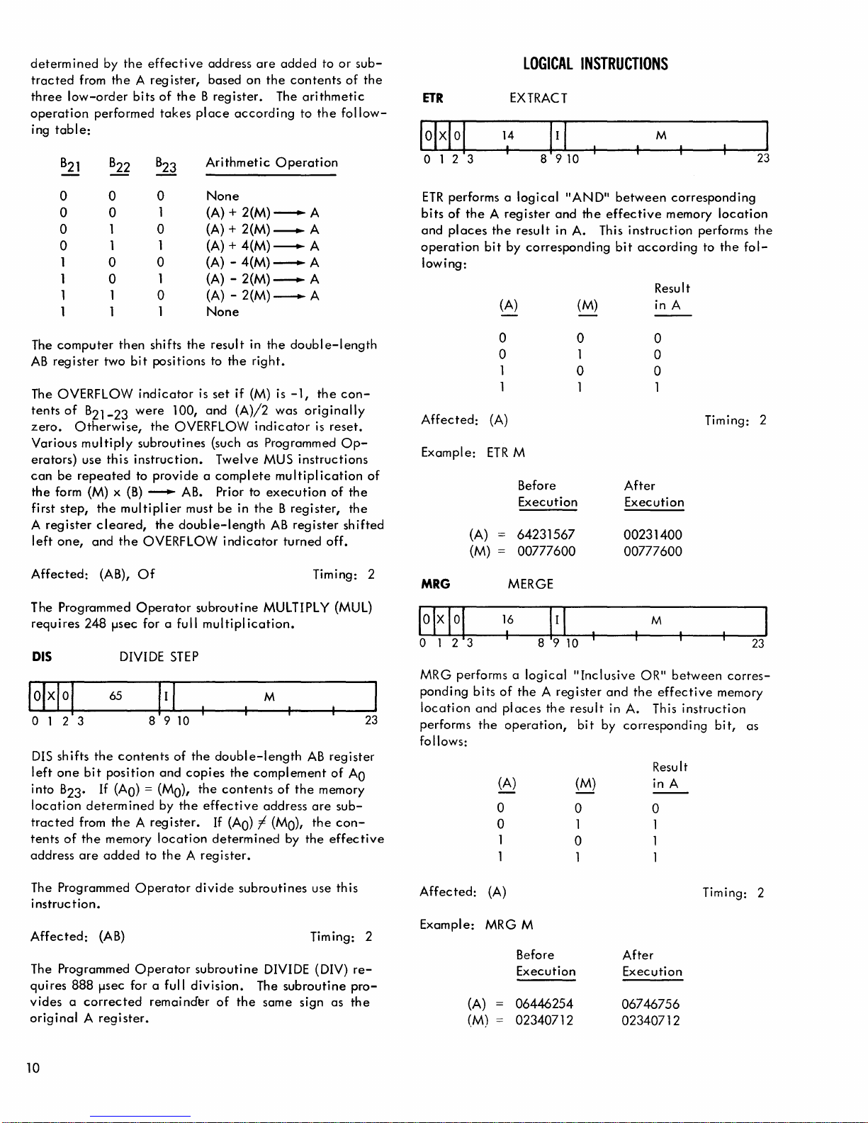
ETR
012
LOGICAL
EXTRACT
14
3
INSTRUCTIONS
M
23
0 0
0 0
0 1 0
0
1
1
1
1 1
The
computer
AB
register
The OVERFLOW
tents
of
zero.
Various
erators)
can
be
the
form (M) x
first
step,
A
register
left
one,
Affected:
The Programmed
requires
DIS
1
0
0
1
then
two
B21-23
Otherwise,
multiply
use
this
repeated
the
multipl
cleared,
and
the
(AB),
248
fJsec for a full
DIVIDE
65
o 1 2 3
DIS
shifts
the
contents
left
one
bit
position
into
B23.
If
(AO)
location
tracted
tents
address
of
determ
from
the A register.
the
memory
are
added
0
1 (A) + 2(M)
1
0
1
0
1
shifts
bit
positions
indicator
were
the
subroutines
instruction.
to
provide a complete
(B)
--+-
the
OVERFLOW
Of
Operator
8 9
and
= (MO),
ined
by
location
to
the A register.
None
(A) + 2(M)
(A) +
(A) - 4(M)
(A) - 2(M)
(A) - 2(M)
None
the
is
100,
and
OVERFLOW
AB. Prior to
ier
must
double-length
subroutine
multiplication.
STEP
10
of
the
copies
the
the
effective
---.
A
----.
A
4(M)
----.
A
---.
A
---.
A
---.
A
result
in
the
double-length
to
the
right.
set
if
(M) is
-1,
the
(A)/2
was
originally
indicator
(such as Programmed
Twelve
be
double-length
If
determined
MUS
execution
in
the B register,
AB
indicator
MULTIPLY (MUL)
M
the
complement
contents
address
(AO)
-I
(MO),
is
instructions
multiplication
register
turned
off.
Timing: 2
AB
of
the
memory
are
the
by
the
con-
reset.
Op-
of
of
the
the
shifted
23
register
of
AO
subcon-
effective
ETR
performs a
bits
of
the A register
and
places
operation
lowing:
the
bit
by
(A)
o
o
1
1
Affected:
Example:
MRG
o 1 2 3
MRG performs a
ponding
iocation
performs
follows:
(A)
(M)
bits
and
the
(A)
ETR
MERGE
16
I
of
piaces
operation,
(A)
0
0
1
1
logical
result
"AND"
and
the
in A. This
corresponding
(M)
o
1
o
1
M
Before
Execution
64231567
00777600
89
10
logical
the A register
"Inclusive
the
result
bit
(M)
0
1
0 1
1
between
effective
instruction
bit
according
Result
in A
o
o
o
1
After
Execution
00231400
00777600
M
OR"
and
the
in A. This
by
corresponding
Result
in A
0
1
corresponding
memory
between
effective
location
performs
to
Timing: 2
memory
instruction
bit,
the
corres-
the
fol-
23
as
The Programmed
i nstruc
tion.
Affected:
The Programmed
quires
888
vides a corrected
original A register.
10
Operator
(AB)
Operator
fJsec for a full
remainder
divide
subroutine
division.
of
the
subroutines
DIVIDE (DIV)
The
subroutine
same
use this
Timing: 2
sign
as
reprothe
Affected:
Example:
(A)
(M)
(A)
MRGM
Before
Execution
06446254
02340712
Timing: 2
After
Execution
06746756
02340712
Page 17
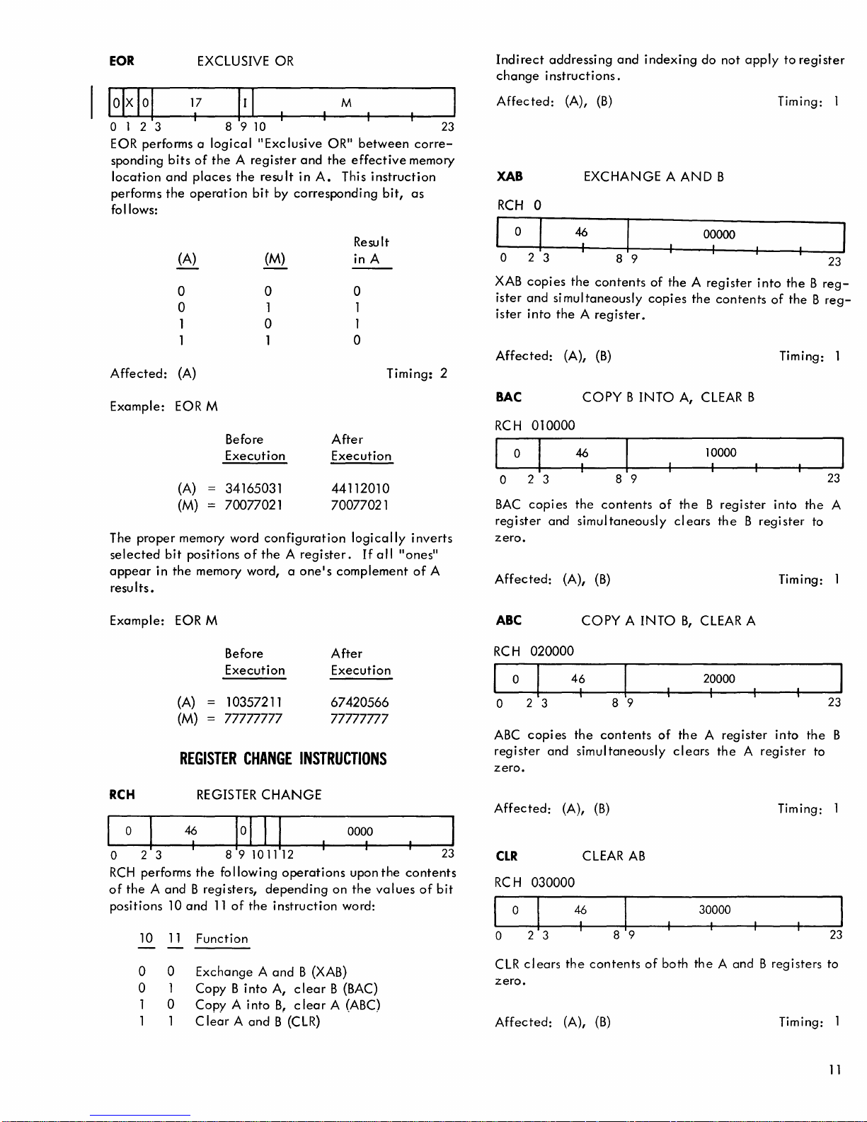
EOR
EXCLUSIVE
OR
Indirect
change
addressing
instructions.
and
indexing
do
not
apply
to
register
I
IOIXIOI
17
o 1 2 3 8 9
EOR performs a
sponding
location
performs
follows:
Affected:
Example:
The
selected
appear
resu
proper
in
Its.
bits
of
and
places
the
operation
(A)
0
0
1
1
(A)
EORM
(A)
(M)
memory word
bit
positions
the
memory word, a
I I I
10
logical
the A register
II
Exc lusive
the
result
bit
(M)
0
1
0
Before
Execution
34165031
70077021
configuration
of
the A register.
by
M
OR"
between
and
the
effective
in
A.
This
corresponding
Result
in A
o
1
1
o
After
Execution
44112010
70077021
logically
If
one's
complement
corre-
memory
instruction
bit,
as
Timing:
inverts
all
"ones"
of
A
23
2
Affected:
XAB
RCH
0
o 2 3
XAB
copies
ister
and
ister
into
Affected:
BAC
RCH
010000
o 2 3
BAC
copies
register
zero.
Affected:
(A),
(B)
EXCHANGE A AND
46
I
8 9
the
contents
si
mul
taneously
the A register.
(A),
(B)
COpy B INTO
46
I
8 9
the
contents
and
simultaneously
(A),
(B)
of
the A register
copies
the
A, CLEAR B
of
the B register
clears
B
00000
I
into
contents
10000
I
the B register
Timing: 1
the B reg-
of
the B reg-
Timing: 1
into
the
to
Timing: 1
23
23
A
Example:
RCH
023
RCH
performs
of
the A and
positions
10
o 0
o 1
1
1 1 C
EOR M
Before
Execution
(A)
(M)
10357211
77777777
REGISTER
REGISTER
46
I
89101112
the
following
B regi sters,
10
and
11
11
Function
Exchange A and
Copy B into
0
Copy A into
lear A and
CHANGE
CHANGE
depending
of
the
instruction
A,
B, c lear
B (CLR)
After
Execution
67420566
77777777
INSTRUCTIONS
0000
I
operations
B (XAB)
clear
upon
on
the
word:
B (BAC)
A (ABC)
va
the
lues
23
contents
of
bit
ABC
RCH
020000
023
ABC
copies
register
zero.
Affected:
CLR
RCH
030000
o 2 3
CLR
clears
zero.
Affected:
COpy A INTO
46
I
the
and
simultaneously
(A),
(B)
CLEAR
46
I
the
contents
(A),
(B)
8 9
contents
AB
B,
of
the A register
clears
of
both
CLEAR A
20000
I
into
the
the A register
to
Timing: 1
30000
the A and B registers
Timing:
23
B
23
to
11
Page 18
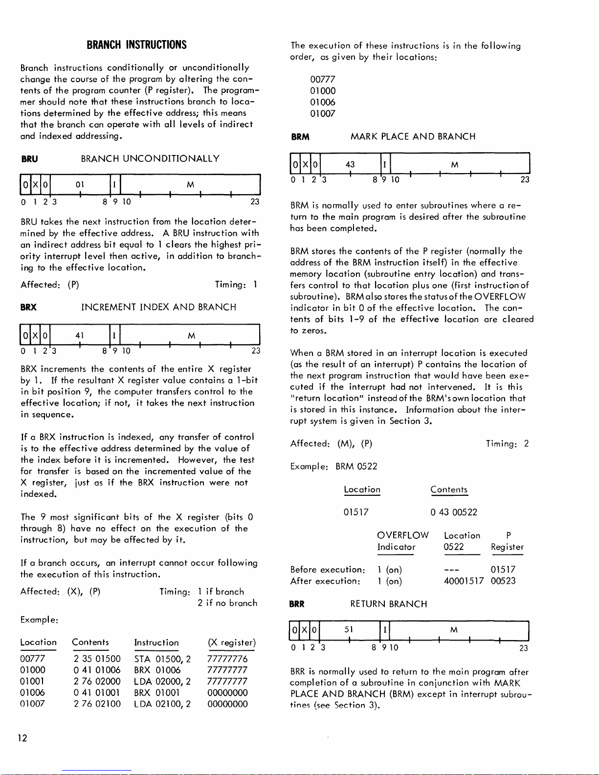
Branch
change
tents
mer
should
tions
that
the
and
indexed
instructions
the
course
of
the
program
note
determined
branch
addressing.
BRANCH
that
by
can
INSTRUCTIONS
conditionally
of
the
program by a
counter
these
the
effective
operate
or
(P
reg
ister).
instructions
address;
with
all
unconditionally
Itering
levels
The
branch
this
of
the
con-
program-
to
loca-
means
indirect
The
order,
BRM
execution
as
given
00777
01000
01006
01007
of
these
by
MARK
instructions
their
PLACE
locations:
AND
is
in
the
BRANCH
following
BRU
o 1 2 3
BRU
takes
mined
an
ority
Affected:
indirect
ing to
by
interrupt
the
BRX
o 1 2 3
BRX
increments
by
1.
If
in
bit
position
effective
in
sequence.
If
a
BRX
is
to
the
the
index
for
transfer
X
register;
indexed.
BRANCH
01
the
next
the
effective
address
level
effective
(P) Timing:
INCREMENT INDEX
41
I
the
the
resultant X register
9,
location;
instruction
effective
before
is
based
just
UNCONDITIONALLY
8910
instruction
address. A BRU
bit
equal
to 1
then
active,
location.
8 9
10
I
contents
the
computer
if
not,
is
indexed,
address
it
is
incremented.
on
as
if
it
determined
the
the
BRX
of
takes
incremented
M
from
the
location
instruction
clears
the
in
addition
AND
M
the
entire X register
value
contains a 1-bit
transfers
any
instruction
control
the
next
transfer
by
However,
highest
to
BRANCH
,
instruction
of
the
value
value
were
deter-
with
pri-
branch-
to
the
control
of
the
test
of
the
not
23
23
o 1 2 3
BRM
is
normally
turn
to
the
main
has
been
completed.
BRM
stores
the
address
memory
fers
subroutine).
indicator
tents
to
When a BRM
(as
the
cuted
II
is
rupt
Affected:
Exampl
control
zeros.
the
next
re
turn
stored
system is
of
location
of
bits
result
program
if
location
in this
e:
the
in
the
(M),
BRM
43
I
used
program
contents
BRM
(subroutine
to
that
BRM
also
bit 0 of
1-9
of
stored
of
an
instruction
interrupt
ll
instead
instance.
given
(P)
0522
Location
M
to
enter
subroutines
is
desired
of
the P register
instruction
location
the
the
in
interrupt) P contains
in
stores
effective
effective
an
interrupt
had
of
Section
plus
the
not
the
Information
itself)
entry
location)
one
status
location.
that
would
intervened.
BRM's own
3.
Contents
after
in
(first
of
location
location
where a re-
the
subroutine
(normally
the
effective
and
instruction
the
OVERFLOW
The
are
is
the
location
have
been
It
location
about
the
Timing: 2
the
trans-
concleared
executed
exe-
is
this
that
inter-
23
of
of
The 9 most
through
instruction,
If
a
branch
the
execution
Affected:
Example:
Location
00777
01000
01001 2
01006
01007
12
significant
8)
have
but
occurs,
(X),
Contents
2 35
041
041
2
of
76
76
no
may
an
this
(P)
01500
01006
02000
01001
02100
bi ts
of
effect
on
be
affected
interrupt
instruction.
Instruction
STA
BRX
LDA
BRX
LDA
the
X regi
the
execution
by
it.
cannot
Timing: 1
01500,2
01006
02000,2
01001
02100/2
occur
2
ster
(bits 0
of
the
following
if
branch
if
no
branch
(X
register)
77777776
77777777
77777777
00000000
00000000
Before
After
execution:
execution:
BRR
o 1 2 3
BRR
is
normally
completion
PLACE
tines
AND
(see
01517
OVERFLOW
Indicator
1 (on)
1 (on)
RETURN
51
I
8
910
used to
of a subroutine
BRANCH
Section
3).
BRANCH
return
in
conjunction
(BRM)
except
o
to
43
0522
40001517
the
00522
Location
M
mai n program
with MARK
in
interrupt
P
Register
01517
00523
23
after
subrou-
Page 19
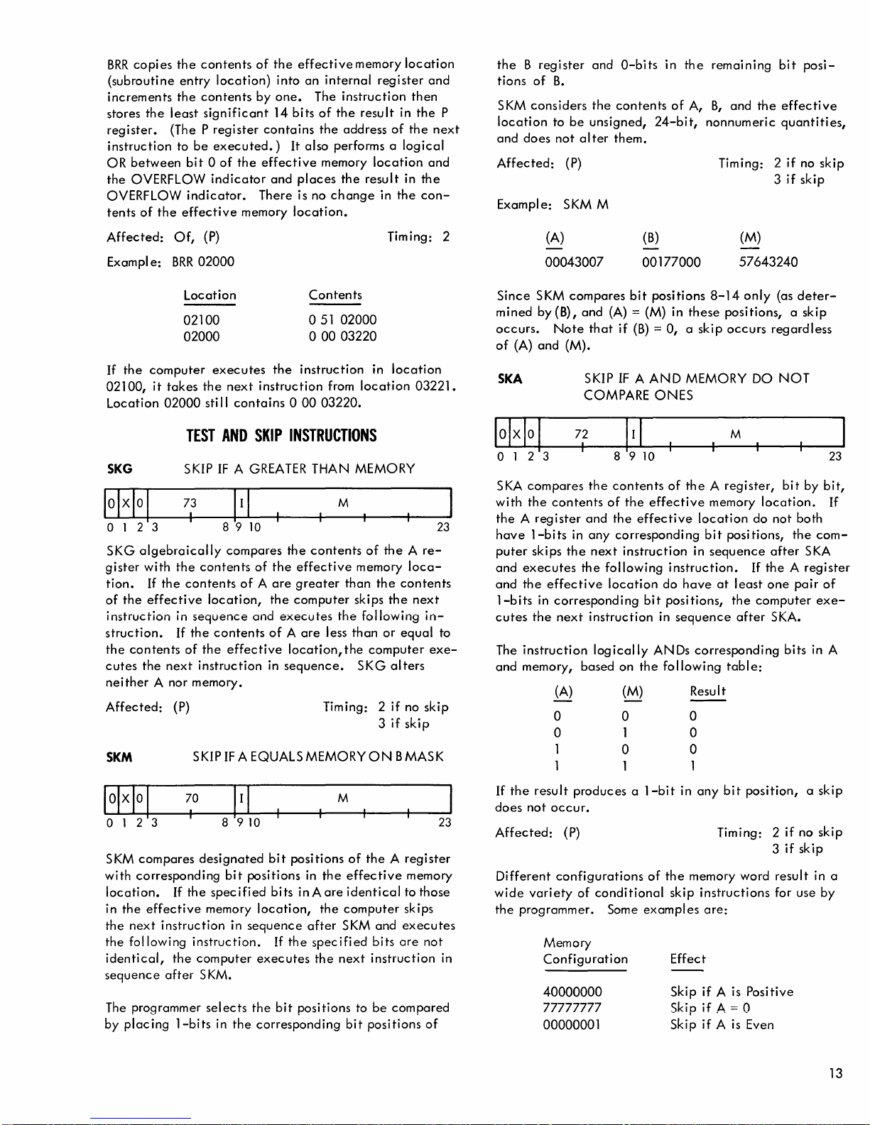
BRR
copies
(subroutine
increments
stores
the
least
register.
instruction
OR
the
OVERFLOW
tents
(The P
between
OVERFLOW
of
the
the
contents
entry
location)
the
contents
significant
register
to
be
executed.)
bit 0 of
indicator
indicator.
effective
of
the
by
one.
14
contains
the
effective
and
There is no
memory
effective
into
an
bits
It also performs a
places
location.
internal
The
instruction
of
the
the
address
memory
the
change
memory
register
result
location
result
in
location
then
in
of
the
logical
in
the
and
the
and
the
con-
P
next
the B register
tions
of
B.
SKM
considers
location
and
Affected:
Example:
does
to
be
not
(P)
SKM M
and
the
contents
unsigned,
al
ter
them.
O-bits in
24-bit,
of
the
A,
remaining
B,
and
the
nonnumeric
Tim
ing: 2
bit
posi-
effective
quantities,
if
no
skip
3
if
skip
Affected:
e:
Exampl
If
the
computer
02100,
Location
it
SKG
o 1 2 3
SKG
algebraically
gister
with
tion.
If
of
the
effective
instruction
struction.
the
contents
cutes
the
neither
Affected:
SKM
A nor memory.
Of,
(P)
BRR
02000
Location
02100
02000
executes
takes
the
next
instruction
02000
sti II
contains 0 00
TEST
AND
SKIP
SKIP
IF A GREATER
73
I
8 9
10
compares
the
contents
the
contents
location,
in
sequence
If
the
of
the
next
instruction
(P) Timing: 2
SKIPIFAEQUALSMEMORYON
of
of A are
and
contents
effective
Contents
o
51
02000
o
00
03220
the
instruction
from
03220.
INSTRUCTIONS
THAN MEMORY
M
the
contents
the
effective
greater
the
computer
executes
of A are
location,
in
sequence.
the
less
than
than
the
Timing: 2
in
location
location
of
the A re-
memory
the
skips
the
following
or
computer
SKG
alters
if
3
if
03221.
loca-
contents
next
in-
equal
exe-
no
skip
skip
BMASK
23
to
(A)
00043007
Since
SKM
compares
mined
by (B), and (A) = (M) in
occurs.
of
(A)
and
Note
(M).
SKA
o 1 2 3
SKA
compares
with
the
contents
the A register
have
1-bits
puter
skips
the
and
executes
and
the
effective
1-bits
in
corresponding
cutes
the
next
The
instruction
and
memory, based on
(A)
0
0
1
1
that
SKIP
COMPARE
72
I
the
contents
of
and
the
in
any
corresponding
next
the
following
location
instruction
logically
(B)
00177000
bit
positions
if
(B) = 0,
IF A AND
ONES
of
the
effective
effective
instruction
instruction.
do
bit
positions,
in
sequence
ANDs
the
following
(M)
0
1 0
0
1
(M)
57643240
8-14
only
these
positions, a skip
a skip
occurs
MEMORY DO
M
the A register,
memory
location
bit
in
sequence
have
corresponding
Result
0
0
1
do
positions,
If
at
least
the
computer
after
table:
(as
deter-
regardless
NOT
23
bit
by
bit,
location.
not
after
the A register
one
SKA.
bits
both
the
pair
If
com-
SKA
of
exe-
in A
70
o 1 2 3
SKM
compares
with
corresponding
location.
the
effective
in
the
next
the
following
identical,
sequence
The programmer
by
placing
I
designated
If
the
specified
memory
instruction
instruction.
the
computer
after S KM.
selects
1-bits
in
bit
bit
positions
bits
location,
in
sequence
executes
the
the
corresponding
positions
If
the
bit
M
of
in
the
effective
in A
are
identical
the
computer
after
SKM
specified
the
next
positions to
bit
23
the A register
memory
to those
skips
and
executes
bits
are
not
instruction
be
compared
positions
in
of
If
the
result
produces a 1-bit
does
not
occur.
Affected:
Different
wide
the
programmer. Some
(P)
configurations
variety
of
Memory
Configuration
40000000
77777777
00000001
of
conditional
examples
in
any
the
memory word
skip
instructions
are:
Effect
Skip
if
Skip
if
Skip
if A is
bit
position,
Timing: 2
A is Positive
A = 0
Even
if
3
if
result
for use by
a skip
no
skip
skip
in a
13
Page 20
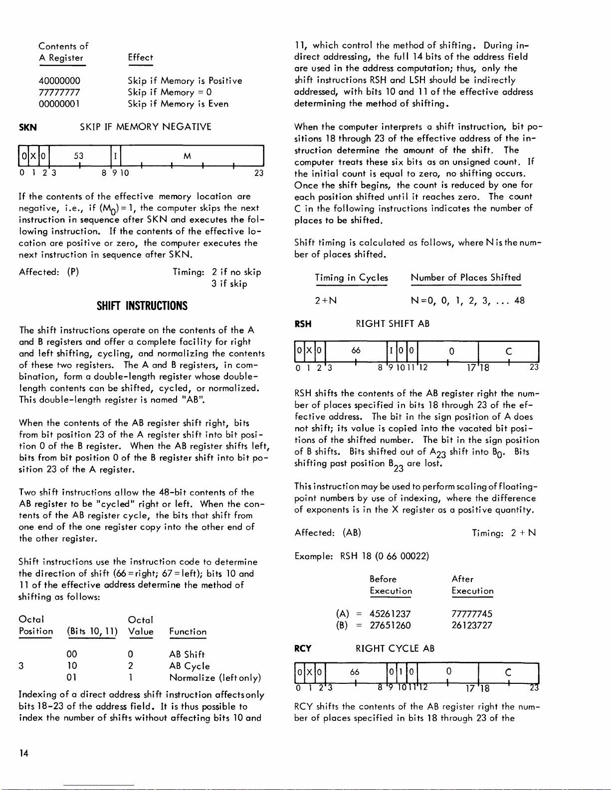
Contents
A Register
40000000
77777777
00000001
SKN
o 1 2 3
If
the
contents
negative,
instruction
lowing
cation
next
instruction.
are
instruction
of
SKIP
53
I
of
i.e.,
if
in
sequence
positive
Effect
Skip
if
Skip
if
Skip
if
IF
MEMORY NEGATIVE
8 9 10
the
effective
(MO)
= 1,
the
after
SKN
If
the
contents
or
zero,
the
in
sequence
after
Memory is
Memory = 0
Memory is Even
memory
computer
and
of
computer
SKN.
M
location
skips
executes
the
effective
executes
Positive
the
the
are
next
the
fol-
lo-
23
11,
which
direct
addressing,
are
used in
shift
instructions
addressed,
determining
When
the
sitions
struction
computer
the
Once
each
C in
places
Shift
ber
18
initial
the
position
the
to
timing
of
places
determine
treats
following
be
control
the
address
RSH
with
bits
the
method
computer
through
these
count
is
shift
begins,
shifted
shifted.
is
calculated
shifted.
the
method
the
full 14
computation;
and
LSH
10
and
of
shifti
interprets
23
of
the
the
amount
six
bits
equal
to
the
count
unti I
it
instructions
as follows,
of
shifting.
bits
of
should
11
of
the
ng.
a shift
effective
of
as
an
zero,
no
is
reaches
indicates
During
the
address
thus,
only
be
indirectly
effective
instruction,
address
the
shift.
unsigned
shifting
reduced
zero.
the
where
N is
in-
field
the
address
bit
of
the
in-
The
count.
occurs.
by
one
for
The
count
number of
the
num-
po-
If
Affected:
The
and B registers
and
of
these
bination,
length
This
When
from
tion 0 of
bits from
sition
Two
AB
register
tents
one
the
other
Shift
the
direction
11
of
shifting
Octal
Position
3
Indexing
bits
index
(P) Timing: 2
shift
instructions
left
shifting,
two registers. The A and B
form a
contents
double-length
the
contents
bit
position
the B register.
bit
position 0 of
23
of
the A register.
shift
instructions
to
of
the
AB
end
of
the
register.
instructions
the
effective
as
follows:
(Bits
00
10 2
01
of a direct
18-23
of
the
number
SHIFT
operate
and
offer a complete
cyc
ling,
double-length
can
be
register
of
the
23
of
allow
be
"cycled"
register
one
regi
use
the
of
shift
(66
address
10, 11)
address
the
address
of
shifts
INSTRUCTIONS
on
the
contents
faci I ity
and
normal
izing
registers,
register
shifted,
the A register
cycle,
ster
= right;
Octal
Value
0
1
cycled,
is named "AB".
AB
register
When
the
AB
the B register
the
48-bit
right
or
left.
the
bits
copy
into
instruction
67=
determine
Function
AB
AB
Normalize
shift
instruction
field.
It
without
is
affecting
shift
shift
register
contents
that
the
code
left); bits 10
the
Shift
Cycle
thus
if
3
if
of
for
the
in
whose
double-
or
normalized.
right,
into
shift
into
When
shift
other
to
determine
method
(left
affects
possible
bits
no
skip
skip
the
A
right
contents
com-
bits
bit
posi-
shifts
left,
bit
of
the
the
con-
from
end
of
and
of
only)
only
to
10
and
po-
Timing in
2+N
RSH
o 1 2 3
RSH
shifts
ber
of
places
fective
not
tions
of
shifting
This
point
of
Affected:
Example:
RCY
lolxlo
address. The
shift; its
of
the
B shifts. Bits
past
instruction
numbers by use
exponents
I
o 1 2 3
RCY
shifts
ber
of
places
Cycles
RIGHT SHIFT
66
I
the
contents
specified
value
shifted
position
may be used
is in
(AB)
RS
H 18 (0
(A)
(B)
RIGHT eye
66
I
the
contents
specified
Number
N
=0,
AB
89101112
of
the
AB
in bits 18 through 23
bit
in
the
sign
is
copied
number. The
shifted
B
of
the X register
66
Before
Execution
45261237
27651260
1011
89
into
out
of
A
are
23
lost.
to
perform
indexing,
00022)
LE
AB
10
I
10
1112
of
the
AB
in bits 18 through 23 of
of
0,
1,
o
I
register
position
the
bit
in
shift
23
scaling
where
as a
After
Execution
77777745
26123727
0
,
register
Places
2,
3,
right
vacated
the
sign
into
the
positive
Timing:
17118
right
Shifted
...
48
C
I
the
num-
of
the
ef-
of A does
bit
posi-
position
BO'
Bits
of
floating-
difference
quantity.
2+N
C
I
the
num-
the
23
1
23
14
Page 21
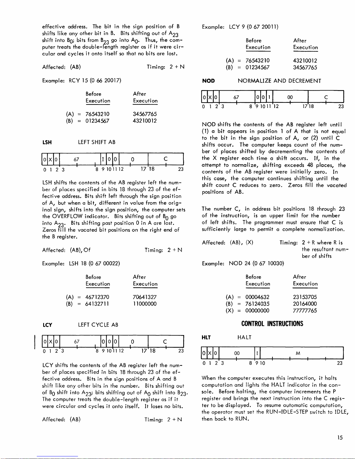
effective
like
shifts
shift
into
puter
treats
cular
and
Affected:
address. The
any
other
bit
BO;
bits from B
the
double-length
cycles
(AB)
it
onto
bit
in
B.
go
23
itself
in
the
Bits
into
register
so
sign
shifting
AO.
that
position
out
of
Thus,
the
as
if
it
were
no
bits
are
Timing: 2 + N
of
A
23
com-
cir-
lost.
B
Example: LCY 9
(A)
(B)
(067
20011)
Before
Execution
76543210
01234567
After
Execution
43210012
34567765
Example: RCY 15 (0 66 20017)
Before
Execution
(A)
(B)
LSH
IoIxIol
o 1 2 3
LSH
shifts
ber
of
places
fective
of
inal
the
into
Zeros
the B register.
Affected:
Example:
address. Bits
A,
but
when a
sign,
OVERFLOW
A23. Bits
fi
II
the
LEFT
67
I
the
contents
specified
shifts
vacated
(AB),
LSH
76543210
01234567
SHIFT
8 9
shift
bit,
into
the
indicator.
shifting
Of
18 (0
67
AB
101112
of
the
in bits 18 through 23
left
different
sign
Bits
past
position
bi t
positions
00022)
After
Execution
34567765
43210012
o
I
AB
register
through
in
value
position,
shifting
on
left
the
of
the
sign
from
the
the
computer
out
of
0 in A
are
the
right
Timing: 2 + N
C
I
num-
the
ef-
position
orig-
sets
BO
go
lost.
end
of
23
NOD
10Ho
1
o 1 2 3
NOD
shifts
(1) a
bit
appears
to
the
bit
in
occur.
shifts
ber
of
places
the X register
attempt
contents
this
shift
positions
The number
of
of
sufficiently
Affected:
Example:
to
normalize,
of
case,
the
count C reduces
of
the
instruction,
left
shifts.
(A
NOD
NORMALIZE
67
I
the
the
AB.
C,
large
B)
101
8 9
contents
in
the
sign
The
computer
shifted
each
AB
register
computer
in
address
is
The programmer must ensure
to
, (X)
24 (0
AND
DECREMENT
0
1
1
10
11
of
position 1 of A that
position
by
decrementing
time
shifting
continues
to
zero.
an
permit a complete
67
10030)
00
1
12
the
AB
of
A,
keeps
a shi ft
upper
occurs.
exceeds
were
initio
Zeros
bit
positions 18 through
limit for
Timing: 2 + R
)18
register
or
count
the
48
Ily
shifting
fill
norma
the
ber
C
I
left
unti I
is not
(2) unti I C
of
If,
zero.
the
resultant
of
equa
the
num-
contents
in
the
places,
until
the
the
vacated
number
that
C is
Ii
zation.
where
shifts
In
R is
num-
23
I
of
the
23
(A)
(B)
Ley
11+/01
o 1 2 3
LCY shifts
ber
of
fective
shift
of
BO
The
were
Affected:
the
places
address. Bits in
like
any
shift
into
computer
circular
(AB)
Before
Execution
46712370
64132711
LEFT
67
I
contents
specified
other
A23; bits
treats
and
cycles
CYC
LE
I
1010
89101112
of
the
in bits
the
bits in
shifting
the
double-length
it
After
Execution
70641327
11000000
AB
JoI
the
onto
o
I
AB
register
18
through 23
sign positions
number. Bits
out
of
itself.
C
left
the
num-
of
the
of
A and B
shifting
AO
shift
into
register
as
if
It
loses no bits.
Timing: 2 + N
ef-
out
B23.
it
23
(A)
(B)
(X)
CONTROL
HLT
lolxlol
o 1 2 3 8
When
the
computation
sole.
Before
register
ter
to
be
the
operator
then
back
HALT
00
I
computer
and
halting,
and
brings
displayed.
must
to RUN.
Before
Execution
00004632
76124035
00000000
1 I I
910
executes
lights
the
the
the
next
To
resume
set
the
After
Execution
23153705
20164000
77777765
INSTRUCTIONS
M
this
instruction,
HALT
indicator
computer
instruction
RUN-IDLE-STEP switch to
increments
automatic
it
in
the
into
the C regis-
computation,
halts
con-
the
23
P
IDLE,
15
Page 22

The
computer
cording
Indirect
instruction,
When
putation
ing
it
resumes
the
and
The
is
to
addressing
the
ceases
executed.
continues
with
RUN-IDLE-STEP
the
interrupt
HALT
set
to
IDLE,
then
executes
the P register.
and
nor
does
the
computer
until
the
light
at
the
If
an
input/output
completed.
occurrence
system
turns
or
when
executes
switch
off
indexing
instruction
end
of
is
is
enabled.
when
an
interrupt
the
next
instruction,
do
not
access
HLT,
all
the
present
operation
Computation
of a program
still
in
the
the
RUN-IDLE-S
occurs.
apply
to
memory.
internal
instruction
is
in
progress,
automatically
interrupt,
RUN
position
TEP
ac-
this
com-
be-
if
switch
This
instruction
switches
BREAKPOINT
the
lowing
is
set
in
Mnemonic
BPT
(S
KS
singly
next
instruction
instruction.
(on),
sequence.
1
020400)
the
BREAKPOINT
tests
the
status
or
in
any
switch
is
reset
in
sequence
If
the
tested
computer
Name
BREAKPOINT 1
executes
of
Instruction
TESTS
of
the
combination.
(off),
the
and
executes
BREAKPOINT
the
Test
BREAKPOINT
If
a
tested
computer
the
switch
next
instruction
Octal
Configuration
04020400
skips
fol-
Affected:
NOP
o 1 2 3
Executing
X
register,
do
not
apply
access
Affected:
EXU
sequence
If
branch
address
sequence
If
skip
If
cade
Affected:
o 1 2 3
EXU
causes
tion
to
the
contents
location
tion,
the
tive
location
the
contents
the
contents
instruction,
program
next
instruction
the
contents
EXU,
the
ing
the
indefinitely.
memory.
initial
Halt
flip-flop
NO
20
I
NOP
does
or
memory.
to
this
None
EXECUTE
23
I
the
contents
be
executed
of
the
is
not a branch,
computer
and
following
of
instruction,
of
the
branch
following
of
control
above
returns
plus
of
the
process
EXU
Determined
cuted
Timing: 1
OPERATION
M
not
affect
Indirect
instruction,
8
910
of
as
an
program
executes
then
executes
the
EXU.
the
effective
program
and
the
EXU.
the
effective
then,
depending
to
one,
effective
repeats,
location
(See
Figure 9 in
by
instruction instruction
the A register, B register,
addressing
nor
does
the
M
the
effective
instruction
counter.
skip,
or
another
the
contents
the
memory
control
not
to
the
memory
on
the
next
following
memory
wi th
plus
one.
exe-
Timing: 1 +
memory
without
If
the
EXU
of
next
instruction
location
goes
to
next
instruction
location
the
skip
instruction,
the
EXU.
location
the
norma I return
This
process
Appendix
and
indexing
instruction
Timing:
loca-
altering
effective
instruc-
the
effec-
are
the
effective
are
deci
or
are
another
can
D.)
executed
sion,
the
23
23
in
a
in
a
be-
cas-
BPT
2
(S
KS
020200)
BPT
3
(SKS
020100)
BPT4
(S
KS
020040)
If
more
than
the
test,
the
any
of
the
1
skip
the
next
es
are
set.
causes
switches 1 and 3 are
case).
Affected:
the
OVT
(SKS
020001)
This
instruction
cator.
next
(clears
skips
following
Affected:
ROV
(EOM
ROV
(clears
Affected:
If
the
instruction
to
zero).
the
next
instruction.
020001)
unconditionally
to
zero).
BREAKPOINT 2
BREAKPOINT 3
BREAKPOINT 4 Test
one
BREAKPOINT
computer
specified
instruction
Thus,
computer
(P)
OVERFLOW
OVERFLOVI INDICATOR
RESET
tests
indicator
in
instruction
(P),
Of
RESET
Of
ski ps
switches
the
instruction
to
skip
both
the
status
is
sequence,
If
the
indicator
OVERFLOW
resets
the
are
if
all
the
set
(2
INSTRUCTIONS
of
on,
the
and
in
sequence
the
Test
Test
switch
next i nstructi
of
next
and 4 are
the
computer
turns
is
OVERFLOW
040
040
040
is
specified
reset,
BPT
Timing: 1
but
the
specified
1,3
instruction
ignored
(040
TEST
OVERFLOW
executes
the
indicator
off,
the
and
executes
Timing: 1
20200
20100
20040
on
if
does
switch-
20500)
unless
in
if
no
skip
2
if
skip
AND
o
40
20001
indi-
computer
the
if
no
skip
2ifskip
o
02
20001
indicator
Timing: 1
in
not
this
the
off
16
Page 23
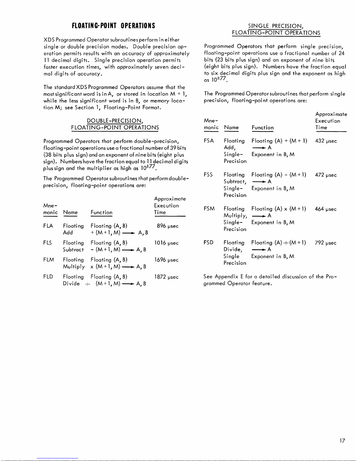
FLOATING-POINT
XDS Programmed
single
or
double
eration
11
faster
mal
The
mostsignificantword
whi
tion
permits
decimal
execution
digits
standard
Ie
the
M;
see
less
Operator
precision
resul ts
digits.
times,
of
accuracy.
XDS Programmed
significant
Section
DOUBLE-PRECISION,
FLOATING-POINT
subroutines
modes.
with
an
Single
precision
with
is
inA,
word is in
1,
Floating-Point
OPERATIONS
perform
D~uble
accuracy
approximately
Operators
or
stored
OPERATIONS
precision
of
approxi
operation
assume
in
location
B,
or
memory
Format.
seven
in
either
permits
that
op-
matel
deci-
the
M + 1,
loca-
SINGLE
FLOATING-POINT
Programmed
y
floating-point
bits
(23
(eight
to
six
as
10±77.
The Programmed
precision,
Mnemonic
Operators
bits
plus
bits
plus
decimal
floating-point
Name
operations
sign)
sign).
digits
Operator
Function
that
and
Numbers
plus
sign
subrouti
operations
use a
PRECISION,
OPERATIONS
perform si ng I e
fractional
an
exponent
have
and
the
nes
that
are:
number
of
nine
the
fraction
exponent
perform
Approxi
Execution
Time
prec i si
bits
as
si
on,
of
24
equal
high
ng I e
mate
Programmed
floating-point
(38
bits
sign).
plussign
The Programmed
precision,
Mnemonic
FLA
FLS
FLM
FLD
Operators
operations
plus
sign)
Numbershave
and
the
floating-point
Name
Floating
Add
Floating Floating
Subtract
Floating Floating
Multiply
Floating
Divide
that
use a fractional
and
an
exponent
the
fraction
multiplier
Operator
Function
Floating
+ (M + 1, M)
- (M +
x (M + 1, M)
Floating
(M +
perform
of
equal
as
high
subroutines
operations
(A,
B)
----.
(A,
B)
1!
M)
----.
(A,
B)
----.
(A,
B)
1,
M)
----.
double-precision,
nine
as
are:
number
to
lo±77.
that
bits
(eight
11
decimal
perform
Approxi
Execution
Time
of
double-
896 !-,sec
A,
B
1016 !-,sec
A,
B
1696 !-,sec
A, B
1872 !-,sec
A,
B
39
plus
digits
mate
bits
FSA
FSS
FSM
FSD
See
grammed
Floating
Add,
Single-
Precision
Floating
Subtract,
SinglePrecision
Floating
Multiply,
SinglePrecision
Floating
Divide,
Single
Precision
Appendix E for a detailed
Operator
Floating
Exponent
Floating
---.A
Exponent
loati
ng (A) - (M +
F
---.A
Exponent
Floating
--.A
Exponent
--.A
feature.
(A) + (M +
in
B,
M
in
B,
M
(A) x (M +
in
B,
M
(A)
+(M
+
in
B,
M
discussion
1)
1)
1)
1)
432
472 !-,sec
464 !-,sec
792 !-,sec
of
the
!-,sec
Pro-
17
Page 24
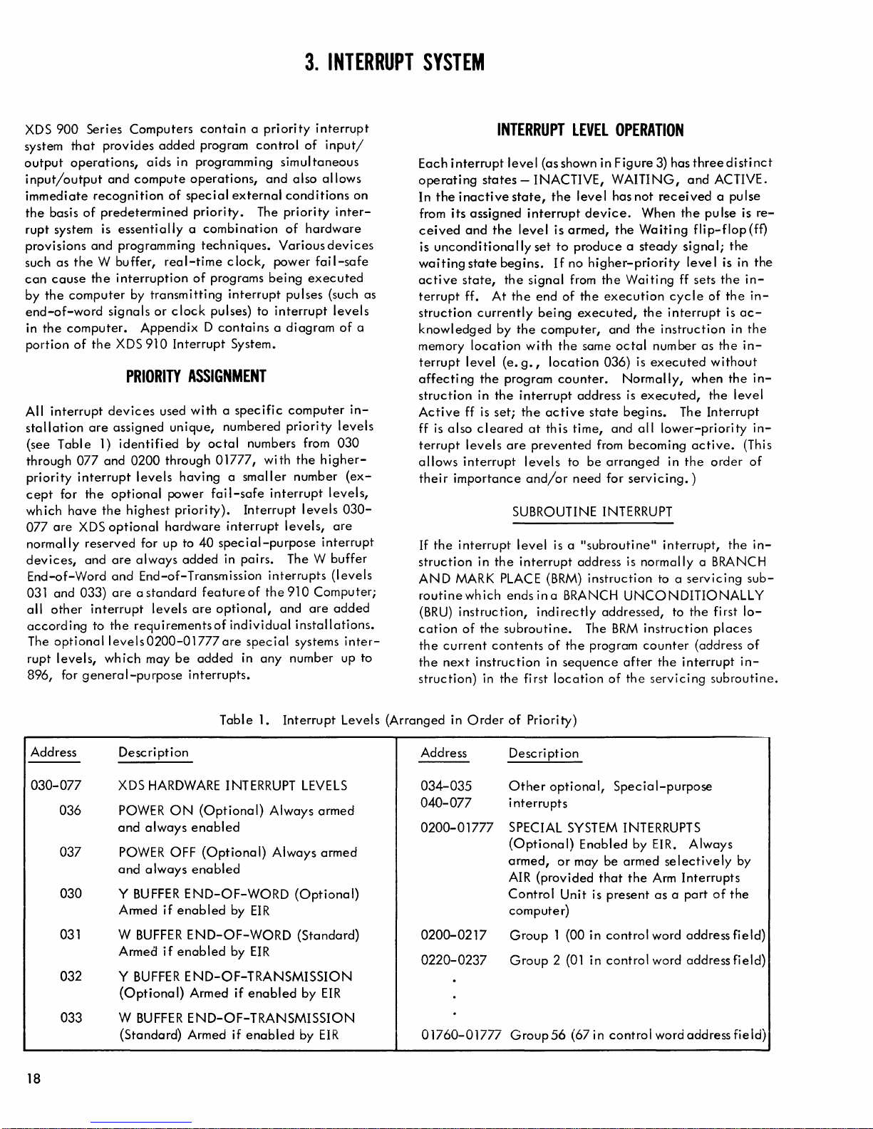
XDS
900
Series
system
output
input/output
immediate
the
rupt
provisions
such
can
by
end-of-word
in
portion
All
stallation
(see
through
priority
cept
which
077
normally
devices,
End-of-Word
031
all
according
The
rupt
896,
that
operations,
basis
of
system is
as
the W buffer,
cause
the
computer
the
computer.
of
interrupt
Table
077
interrupt
for
the
have
are
XDS
reserved
and
and
033)
other
optional
levels,
for
general-purpose
Computers
provides
aids
and
compute
recognition
predetermined
essentially a combination
and
programming
the
interruption
by
transmitting
signals
the
or
Appendix D contains a diagram
XDS
910
PRIORITY
devices
are
assigned
1)
identified
and
0200
levels
optional
the
highest
optional
for up to
are
always
and
End-of-
are a standard
interrupt
to
levels0200-01
which
levels
the
requirementsof
may
contain a priority
added
program
in programming
operations,
of
special
priority.
techniques.
real-time
of
programs
clock
pulses) to
Interrupt
ASSIGNMENT
used
with a specific
unique,
by
octal
through
having a smaller
power
hardware
fail-safe
priority).
40
added
Transmission
feature
are
777
be
added
interrupts.
control
simultaneous
and
also
external
clock,
interrupt
System.
numbered
01777,
interrupt
special-purpose
in
pairs.
optional,
individual
are
in
conditions
The
priority
of
Various
power
being
pulses
interrupt
computer
priority
numbers from
wi
th
number
interrupt
Interrupt
levels,
The W
interrupts
of
the
910
and
installations.
special
any
systems
number
3.
INTERRUPT
interrupt
of
input!
allows
on
inter-
hardware
devices
fail-safe
executed
(such as
levels
of
a
in-
levels
030
the h igher-
(ex-
levels,
levels
030-
are
interrupt
buffer
(levels
Computer;
are
added
inter-
up
to
SYSTEM
INTERRUPT
Each
interrupt
operating
In
the
inactive
its
from
ceived
is
unconditionally
waiting
active
terrupt
struction
knowledged
memory
terrupt
affecting
struction
Active
ff
terrupt
allows
their
If
struction
AND
routine
cation
the
the
struction)
is
the
(BRU)
current
next
state,
also
interrupt
importance
interrupt
MARK
instruction,
of
level
states -INACTIVE,
state,
assigned
and
the
level
state
begins.
the
ff.
At
the
currently
by
the
location
level
(e.
the
program
in
the
interrupt
ff is
set;
cleared
levels
are
SUBROUTINE INTERRUPT
level
in
the
interrupt
PLACE
which
ends
the
subroutine.
contents
instruction
in
the
LEVEL
(as shown in
the
level
interrupt
is
armed,
set
to
produce a steady
If
no
signal
from
end
of
being
executed,
computer,
with
the
g.,
location
counter.
address
the
active
at
this
time,
prevented
levels
to
and/or
first
need
is a
address is
(BRM)
in a BRANCH
indirectly
of
the
in
sequence
location
OPERATION
Figure
WAITING,
has
not
device.
higher-priority
the
same
state
from
be
"subroutine"
instruction
The
program
When
the
Waiting
the
Waiting
execution
the
and
the
octal
036) is
Normally,
is
executed,
begins.
and
all
becoming
arranged
for
servicing.
normally
UNCONDITIONALLY
addressed,
BRM
instruction
counter
after
of
the
3) has
three
and
ACTIVE.
received
the
pu Ise is
flip-flop(ff)
signal;
level
ff sets
cycle
of
interrupt
instruction
number as
executed
lower-priority
in
interrupt,
to a
the
servicing
when
The
active.
the
)
a BRANCH
servicing
to
the
(address
interrupt
without
the
Interrupt
order
first
places
subroutine.
distinct
a pulse
the
is in
the
in-
the
in-
is
ac-
in
the
the
in-
the
level
(This
of
the
sub-
lo-
of
in-
re-
the
in-
in-
in-
Table
1.
Interrupt
Address
030-077
036
037
030
031 W
032
033
Description
XDS
HARDWARE
POWER
and
POWER
and
Y
Armed
Armed
Y
(Optional)
W
(Standard)
ON
always
OFF
always
BUFFER
if
BUFFER
if
BUFFER
BUFFER
INTERRUPT
(Optional)
enabled
(Optional)
enabled
END-OF-WORD
enabled
END-OF-WORD
enabled
END-OF-TRANSMISSION
Armed
END-OF-TRANSMISSION
Armed
by
EIR
by
EIR
if
enabled
if
enabled
Always
Always
18
Levels
LEVELS
armed
armed
(Optional)
(Standard)
by
EIR
by
EIR
(Arranged
Address
034-035
040-077
0200-01777
0200-0217
0220-0237
01760-01777
in
Order
of
Priority)
Description
Other
optional,
interrupts
SPECIAL SYSTEM INTERRUPTS
(Optional)
armed,
AIR
(provided
Control
computer)
Group
Group 2 (01
Group56
or
may
Unit
1 (00
(67in
Enabled
be
that
is
present
in
control
in
control
control
Special-purpose
by EIR.
armed
the
Always
selectively
Arm
Interrupts
as a part
word
address
word
address
word
address
of
by
the
field)
field)
field)
Page 25
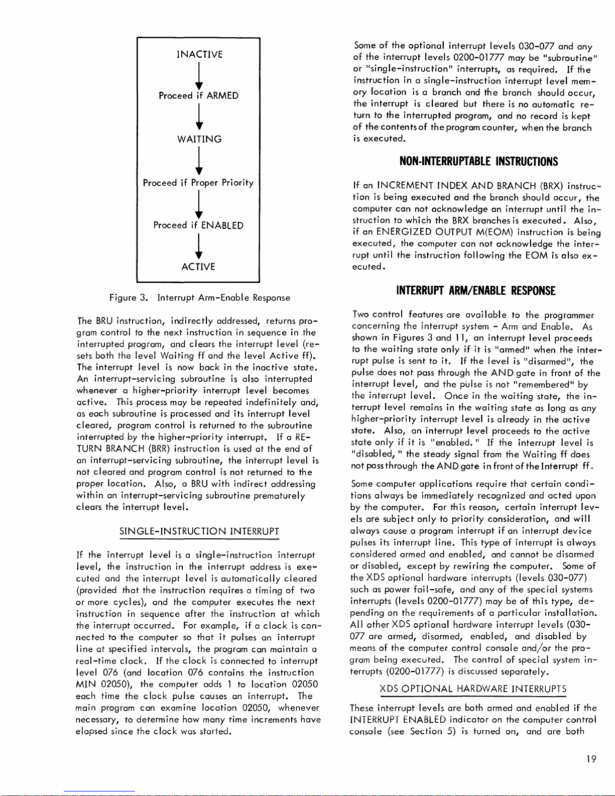
INACTIVE
Proceed
WAITING
~
if
ARMED
~
Some
of
the
optional
of
the
interrupt
or
"single-instruction"
instruction
ory
location
the
interrupt
turn
of
the
is
executed.
to
the
contents
in a
is a
is
interrupted
interrupt
levels
0200-01777
interrupts,
single-instruction
branch
cleared
of
the
and
but
program,
program
levels
may
as
interrupt
the
branch
there
is no automati<;:
and
counter,
030-077
be
"subroutine"
required.
should
no
record
wh
en
and
level
the
any
If
the
mem-
occur,
re-
is
kept
branch
Proceed
Figure
The
BRU
gram
control
interrupted
sets
both
The
interrupt
An
interrupt-servicing
whenever a higher-priority
active.
as
each
cleared,
interrupted
TURN BRANC H
an
interrupt-servicing
not
cleared
proper
within
clears
If
level,
cuted
(provided
or
instruction
the
nected
line
real-time
level
MIN
each
main
necessary,
elapsed
location.
an
the
the
interrupt
the
and
more
interrupt
to
at
specified
076
02050),
time
program
3.
instruction,
to
the
program,
the
level
level
This process may
subroutine
program
by
the
(BRR)
and
program
interrupt-servicing
interrupt
SINGLE-INSTRUCTION
level
instruction
the
interrupt
that
the
cyc
I es),
in
sequence
occurred.
the
computer
clock.
(and
location
the
the
clock
can
to
determine
since
the
if
Proceed
ACTIVE
Interrupt
indirectly
next
instruction
and
Waiting H and
is now
subroutine
is
processed
control
higher-priority
instruction
subroutine,
control
Also, a
level.
is a single-instruction
in
level
instruction
and
the
after
For
so
intervals,
If
the
clock
computer
pulse
examine
how
clock
was
~
Proper
Priority
~
if
ENABLED
~
Arm-Enable
addressed,
clears
the
the
back
in
is
interrupt
be
repeated
and
is
returned
interrupt.
is used
the
is
not
BRU
with
subroutine
INTERRUPT
the
interrupt
is
automatically
requires a timing
computer
the
instruction
example,
that
it
pulses
the
program
is
connected
076
contains
adds 1 to
causes
location
started.
many
an
time
Response
in
sequence
interrupt
level
the
inactive
also
level
indefinitely
its
interrupt
to
the
at
interrupt
returned
indirect
prematurely
address
executes
if a
an
can
the
location
interrupt.
02050,
increments
returns
interrupted
subroutine
the
clock
to
instruction
pro-
in
level
Active
state.
becomes
and,
level
If
a RE-
end
level
to
the
addressing
interrupt
is
exe-
cleared
of
two
the
next
at
which
is
interrupt
maintain
interrupt
02050
The
whenever
have
the
(re-
H).
of
con-
NON·INTERRUPTABLE
If
an
INCREMENT INDEX
tion
is
being
executed
computer
struction
if
an
executed,
rupt
ecuted
can
not
to
which
ENERGIZED OUTPUT M(EOM)
the
computer
until
the
instruction
.•
INTERRUPT
Two
control
concerning
shown in
to
the
rupt
pulse
pulse
does
interrupt
the
interrupt
terrupt
higher-priority
state.
state
only
is
a
"disabled,
not
pass
Some
computer
tions
always
by
the
els
are
always
pulses
considered
or
disabled,
the
XDS
such
as
interrupts
pending
All
other
077
are
means
of
gram
being
terrupts
interrupt
These
INTERRUPT ENABLED
console
features
the
interrupt
Figures 3 and
waiting
level
Also,
through
computer.
subject
cause
its
power
(0200-01777)
XDS
is
sent
not
level,
level.
remains
an
if
it
II
the
be
a program
interrupt
armed
except
optional
fail-safe,
(levels
on
the
XDS
optional
armed,
the
computer
executed.
OPTIONAL
(see
Section
state
pass
interrupt
is
steady
theANDgate
appl
immediately
only
requirements
disarmed,
levels
and
and
acknowledge
the
BRX
can
following
ARM/ENABLE
are
avai
system - Arm
11,
only
if
to
it.
If
through
the
pulse
Once
in
the
level
interrupt
"enabled.
signal
ications
For
this
to
priority
interrupt
line.
This
and
enabled,
by
rewiring
hardware
and
0200-01777)
hardware
control
The
is
discussed
HARDWARE
are
both
indicator
5)
is
INSTRUCTIONS
AND
BRANCH
the
branch
an
interrupt
branches
not
is
instruction
acknowledge
the
RESPONSE
labl
e to
an
interrupt
it
is
"armed"
the
level
is
the
AN D gate
is
not
II
remembered
in
the
waiting
waiting
level
II
require
recognized
reason,
interrupts
any
of a particular
enabled,
control
turned
state
is
already
proceeds
If
the
interrupt
from
the
in
front
of
that
certain
consideration,
if
an
type
of
interrupt
and
cannot
the
computer.
(levels
of
the
may
be
interrupt
and
consol e
of
special
separately.
INTERRUPTS
armed
and
on
the
on,
(BRX)
should
executed.
and
"disarmed",
Waiting
interrupt
of
and/or
computer
until
EOM
is
the
programmer
Enable.
level
when
in
front
state,
as
long
in
the
to
the
the
Interrupt
certain
and
acted
interrupt
be
030-077)
special
this
type,
installation.
levels
disabled
enabled
and
are
occur,
the
proceeds
and
is
disarmed
the
system
instruc-
the
Also,
is
being
inter-
also
ex-
As
the
inter-
the
of
II
by
the
in-
as
any
active
active
level
ff
does
H.
condi-
upon
lev-
will
device
always
Some
systems
de-
(030-
by
pro-
if
the
controi
both
the
in-
the
is
of
in-
19
Page 26
disarmed
terrupt
not
button
interrupt
INTERRUPT ENABLED
after,
with
being
Whenever
position,
ditionally
receiving
proceed
proceed
lows.
turns
If
any
ENABLE
able
the
rupt
terrupt
interrupt
cleared.
leased,
els
and
disabled
levels
considered
affected
the
to
ff is in
INTERRUPT ENABLED
levels
remain
by
this
on
the
computer
levels
and
the
indicator
INTERRUPT ENABLE
executed.
INTERRUPT ENABLE SWITCH
this
switch
the
INTERRUPT ENABLED
turned
an
to
to
When
the
interrupts
switch
levels
levels
If
the
on.
interrupt
the
waiting
the
active
the
switch
COMPUTER
occur
is in
the
reset
030-077
0200-01777
in the
the
Enable
indicator
armed
and
INTERRUPT
INSTRUCTIONS
Two
mach
ine
instructions
Enable
of
EIR
EOM
EIR
INTERRUPT ENABLED
are
ity
Interrupt
interrupt
the
INTERRUPT ENABLE
Affected:
OIR
EOM
DIR
INTERRUPT ENABLE
ff,
and
two
the
INTERRUPT ENABLED
E!"~ABLE
020002
unconditionally
in
the
waiting
is
acknowledged,
levels
levels
Enable
unconditionally
ff is
INTERRUPT ENABLED
020004
state,
030-077
0200-01777
set,
DISABLE
if
the
indicator
always
indicator.)
control
the
Interrupt
indicator
may
be
is
manually
Any
pulse
state.
state
is
position.
during
the
ENABLE
state
are
disarmed
active
ff
remains
enabled.
armed
Whenever
console
ff
is
controlled
switch
held
controllable
while
Any
in
as
soon as
released,
the
time
position,
when
the
indicator
and
are
disabled.
state
is
set
when
on
and
ENABLE/DISABLE
AND
are
used
instructions
INTERRUPTS
sets
the
indicator.
and
regardless
switch.
INTERRUPTS
resets
switch
indicator.
Enable
the
one
proceeds
remain
remain
the
is in
are
If
with
armed
of
the
Enable
the
is
turned
and
enabled
the
is
pressed,
are
cleared,
turned
the
off.
by
the
and/or
in
the
indicator
interrupt
indicator
the
waiting
their
it
automatically
the
switch
is
turned
disabled,
However,
are
processed
the
switch
the
interrupt
the
priority
INTERRUPT
and
is
TESTS
to
set
and
used to
ff
to
enabled)
COMPUTER
test
and
turns
any
interrupt
the
higher
the
active
and
enabled
position
ff. Also,
002
as
002
off.
(In-
are
START
all
and
the
There-
operator
program
ENABLE
is
uncon-
levels
is
on
state
al-
re-
the
En-
released,
off,
inter-
and
in-
any
unti I
is
re-
lev-
reset
the
the
status
20002
on
the
levels
prior-
state.
(and
long
as
of
the
Timing: 1
20004
if
the
position,
the
INTERRUPT ENABLED
rupt
levels
030-077
terrupt
interrupt
unti I the
by
the
tion
cator
Thus,
never
has
rupt
rupt
in
Affected:
lET
S
If
puter
cutes
Affected:
lOT
S
If
instruction
puter
the
Affected:
Note:
levels
0200-01777
pulses
to
indicator
execution
ENABLE
resets
and
the
on
been
levels
levels
the
KS
020004
the
INTERRUPT ENABLED
skips
the
KS
020002
the
indicator
skips
following
of
position
the
Enable
does
not
switch
EIR.
When
executed,
030-077
0200-01777
active
state
INTERRUPT ENABLED Timing:
INTERRUPT ENABLED
(Skip
the
next
following
(P) Timing: 1
INTERRUPT DISABLED
(Skip
in
sequence.
the
next
instruction.
(P)
EIR
and
DIR
mode,
nal Test
Output
and
mode
Instructions).
END·OF·WORD/END·OF·
INTERRUPT
A program
direct,
ial
input/output
trol
In
the
interrupts
buffer
as
the
input).
can
use
program-controlled,
mode,
buffer
occur
to
the
buffer
This is
see
Section
control
peripheral
is
filled
the
are
disarmed
levels
is
again
an
EIR.
when
H,
disarm
may
be
the
the
indicator
are
disarmed
are
are
processed
if
Interrupt
instruction
instruction.
if
Interrupt
is
on,
the
If
instruction
are
EOM's
lET
and
(see
the
Wand
instructions
4)
mode,
as
each
word is
device
from
end-of-word
indicator
are
030-077
turned
However,
DIR
but
or
disable
used to
swi
tch
disabled,
indicator
computer
the
IDT
Section
is
turned
and
disabled,
disabled.
are
not
on
by
if
the
is
executed,
does
not
turn
the
override a DIR,
is
released
is
turned
and
disabled,
but
until
cleared.
System
is
in
sequence
TEST
System
executes
indicator
in
sequence
Tim
ing:
in
the
Internal
are
SKS's in
4,
Primary
TRANSMISSION
OPERATIONS
Y buffers
input/output
(EOM's
control
the
the
in
this
type
program
transmitted
(on
output),
peripheral
interrupt.
off,
and
Any
subsequent
IIrememberedll
the
switch
switch
the
off
the
interrupt
after a DIR
off,
interinter-
any
interrupts
Enabled)
0
40
on,
the
and
exe-
if
2
if
Disabled)
0
40
the
is
off,
the
and
executes
1 if no
" • r
L
IT
SKiP
Control
the
Inter-
Input/
as
single-word,
buffers.
the
buffer
of
operation.
can
specify
from
or
as soon
device
The program
inter-
in-
or
is in
instruc-
indi-
levels.
but
20004
com-
no
skip
skip
20002
next
com-
skip
~ I .~_
Spec-
con-
that
the
(on
20
Page 27
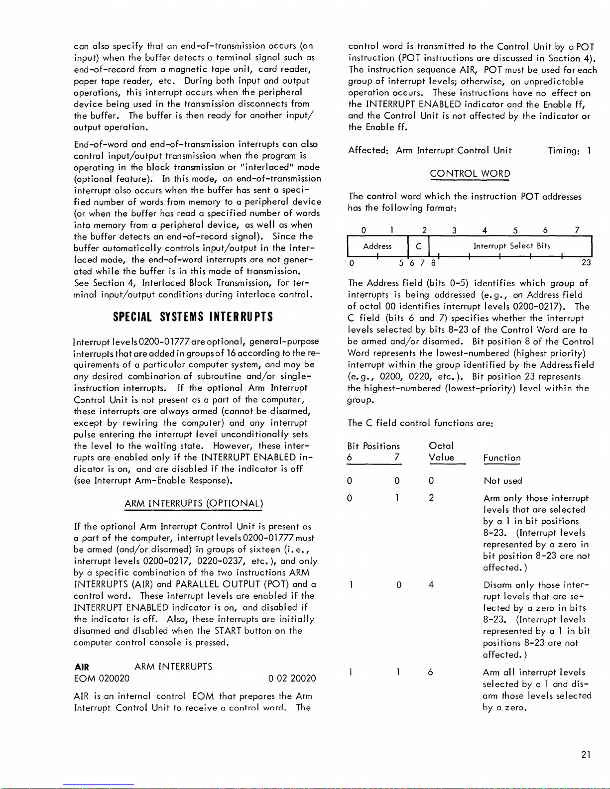
can
also
specify
input)
when
end-of-record
paper
tape
operations,
device
the
output
.
End-of-word
control
operating
(optional
interrupt
fied
(or
into
the
buffer
laced
ated
See
minal
being
buffer.
operation
input/output
in the
feature).
also
number
when
the
memory from a
buffer
automatically
mode,
while
Section
input/output
SPECIAL
Interrupt
interrupts
quirements
any
instruction
Control
these
except
pulse
the
rupts
dicator
(see
levels
that
desired
Unit is
interrupts
by
entering
level
are
enabled
is
Interrupt
to
on,
that
an
end-of-transmission
the
buffer
detects a terminal
from a
reader,
this
used in
The
and
occurs
of
buffer
detects
the
the
4,
magnetic
etc.
During
interrupt
buffer
•
end-of-transm
block
words from memory to a
an
end-of-word
buffer
Interlaced
occurs
the
transmission
is
then
transmission
transmission
In
this
mode,
when
the
has
read a specified
peripheral
end-of-record
con-trois
is in
this
Block Transm ission, for
conditions
SYSTEMS
0200-0
are
of a particular
combination
interrupts.
rewiring
the
the
and
Arm-Enable
added
not
present
are
always
interrupt
waiting
only
are
1777
in
If
the
computer)
state.
if
disabled
are
groups
computer
of
the
as a part
armed
the
Response).
occurs
signal
tape
unit,
card
both
input
and
when
the
peripheral
disconnects
ready
for
another
ission
interrupts
when
the
program is
or
lIinteriaced
an
end-of-transmission
buffer
has
sent a speci-
peripheral
number
device,
input/output
interrupts
mode
during
as
well
signal).
in
are
of
transmission.
interlace
as
Since
the
not
control.
INTERRUPTS
optiona
subroutine
optional
level
INTERRUPT ENABLED
if
I,
genera
of
16
according
system,
and/or
Arm
of
the
computer,
(cannot
unconditionally
However,
the
and
any
indicator
be
these
I-purpose
and
Interrupt
disarmed,
interrupt
(on
such
reader,
output
from
input/
can
also
li
mode
device
of
words
when
the
inter-
gener-
ter-
to
the
may
single-
sets
inter-
in-
is
off
as
re-
be
control
instruction
The
group
operation
the
and
the
Affected:
The
has
word is
(POT
instruction
of
interrupt
occurs.
INTERRUPT ENABLED
the
Control
Enabl e ff.
Arm
control
the
word
following
o
Address
I
o
The Address
interrupts
of
octal
C
fi
eld
levels
be
armed
Word
interrupt
(e.
g.,
the
highest-numbered
group.
The C
Bit Positions
6 7
o
567
field
is
being
00
identifi
(bits 6 and
selected
and/or
represents
with
in
0200,
0220,
field
control
o
transmitted
instructions
sequence
levels;
Unit
Interrupt
CONTROL
which
format:
2
AIR, POT must
These
instructions
is
not
Control
the
3
8
(bits
0-5)
addressed
es
interrupt
7)
spec
by
bits
8-23
disarmed.
the
lowest-numbered
the
group
etc.)e
(lowest-priority)
functions
Octal
Value
o
to
the
Control
are
discussed
otherwise,
indicator
affected
instruction
Interrupt
I I I
identifies
ifies
of
Bit
identifi
Bit
are:
an
and
by
Unit
WORD
4
Select
(e.g.,
levels
whether
the
Control
position 8 of
ed
by
position
Function
Not
used
Unit
by a POT
in
Section
be
used for
unpredictable
have
no
effect
the
Enabl,e ff,
the
indicator
Timing: 1
POT
addresses
6
5
Bits
which
an
0200-0217).
(highest
level
Address
the
interrupt
Word
the
the
Address
23
represents
within
group
priority)
4).
each
on
or
7
23
of
field
The
are
to
Control
fi
eld
the
ARM
INTERRUPTS
If
the
optional
a
part
of
be
armed
interrupt
by a
specific
INTERRUPTS (AIR)
control
INTERRUPT ENABLED
the
disarmed
computer
AIR
EOM
AIR
Interrupt
word.
indicator
020020
is
an
Arm
the
computer,
(and/or
levels
combination
is
and
disabled
control
ARM
internal
Control
Interrupt
interruptlevels0200-01777must
disarmed)
0200-0217,
and
PARALLEL
These
interrupt
indicator
off.
Also,
when
console
INTERRUPTS
control
Unit to
Control
in
0220-0237,
of
the
these
the
is
pressed.
EOM
receive a control
(OPTIONAL)
Unit
groups
of
sixteen
etc.),
two
instructions
OUTPUT (POT)
levels
are
enabled
is
on,
and
interrupts
START
button
that
prepares
is
present
(i.
and
disabled
are
initially
on
o
02
the
word.
as
e.,
only
ARM
and
if
the
if
the
20020
Arm
The
o
a
o
2
4
6
Arm
only
I
evels
that
by
a 1 in
8-23.
represented
bit
affected.
Disarm
rupt
lected
8-23.
represented
posi
affected.
Arm
sel
arm
by
(Interrupt
position
only
levels
by a
(Interrupt
tions
all
ected
those
a
zero.
interrupt
by a 1
those
are
bit
positions
by a zero
8-23
)
those
that
zero
by
8-23
)
levels
interrupt
selected
level
are
not
inter-
are
se-
in
bits
levels
ali n bit
are
not
levels
and
dis-
selected
s
in
21
Page 28
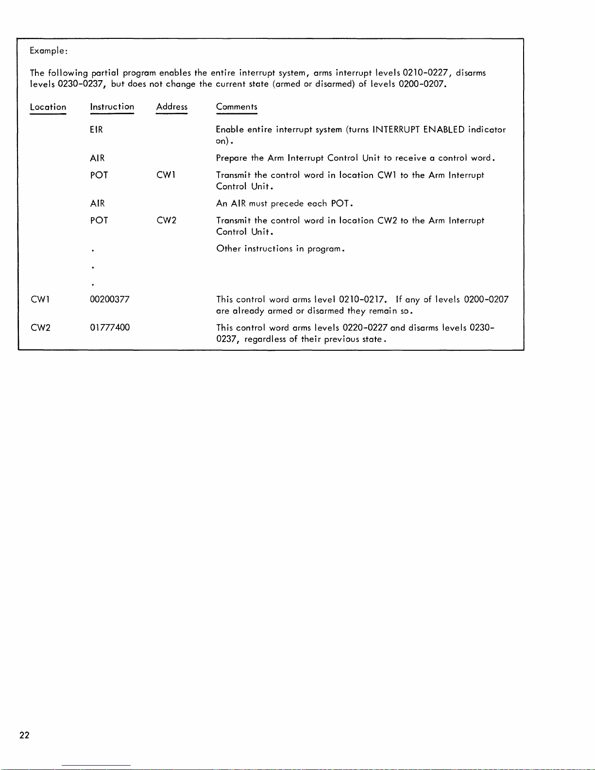
Example:
The
following
levels
0230-0237,
partial
but
program
does
not
enables
change
the
the
entire
current
interrupt
state
system,
(armed or
arms
interrupt
disarmed)
of
levels
levels
0210-0227,
0200-0207.
disarms
Location
CW1
CW2
Instruction
EIR
AIR
POT
AIR
POT
00200377
01777400
Address
CW1
CW2
Comments
Enable
entire
on) •
Prepare
the
Transmit
Control
An
AIR
Unit.
must
Transmit
Control
Other
This
are
This
0237,
Unit.
instructions
control
already
control
regardless
Arm
the
control
precede
the
control
word arms
armed
word arms
interrupt
Interrupt
word in
word in
in
or
of
their
system (turns INTERRUPT ENABLED
each
Control
POT.
Unit to
location
location
receive a control
CW1
to
the
CW2 to
the
Arm
Arm
program.
level
disarmed
levels
previous
0210-0217.
they
0220-0227
state.
remain
and
If
any
so.
disarms
of
levels
Interrupt
Interrupt
0200-0207
levels
indicator
word.
0230-
22
Page 29
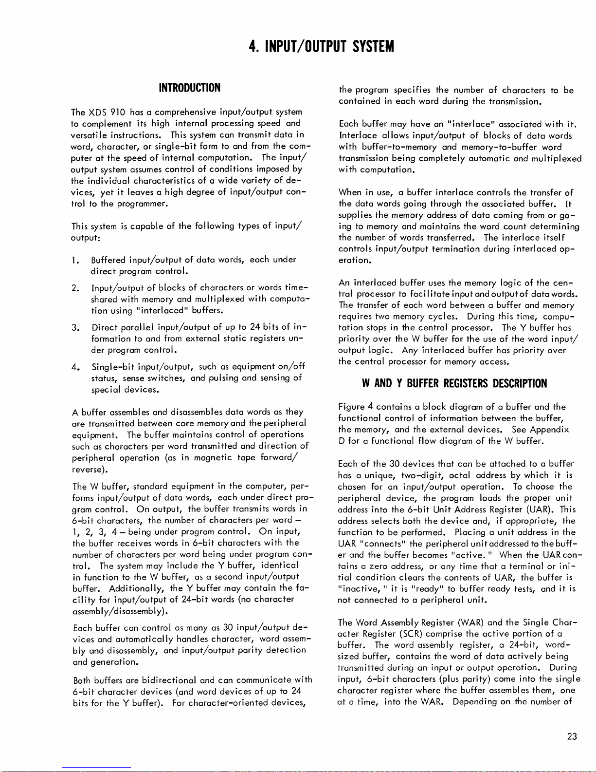
4.
INPUT/OUTPUT
SYSTEM
The
XDS
910 has a
complement
to
versatile
word,
puter
output
the
vices,
trol to
This system is
output:
1. Buffered
2.
3.
4.
instructions.
character,
at
the
system assumes
individual
yet
it
the
programmer.
direct
program
Input/output
shared
tion
using
Direct
formation to
der
program
Single-bit
status,
spec ial
INTRODUCTION
comprehensive
its high
or
single-bit
speed
of
internal
characteristics
leaves a high
capable
input/output
control.
of
blocks
with
memory
"interlaced"
parallel
sense
devices.
input/output
and
from
control.
input/output,
switches,
internal
This system
control
degree
of
the
following
of
data
of
and
multiplexed
buffers.
external
and pulsing
input/output
processing
can
form to and from
computation.
of
conditions
of a wide
of
words,
characters
of
up to
static
such as
speed
transmit
imposed by
variety
input/output
types
each
or words
with
24
registers
equipment
and
system
data
the
The
input/
of
of
input/
under
computa-
bits
of
on/off
sensing
and
in
com-
decon-
time-
in-
un-
of
the
program
contained
Each
buffer
Interlace
with
buffer-to-memory
transmission
with
computation.
When in use, a
the
data
supplies
ing to memory
the
number
controls
eration.
An
interlaced
tral
processor to
transfer
The
requires
tation
priority
output
the
central
specifies
in
each
may
allows
being
words
the
memory
of
input/output
of
two memory
stops in
over
the W buffer
logic.
processor for memory
WAND Y BUFFER
word
have
input/output
completely
buffer
going
through
address
and
maintains
words
transferred.
buffer
uses
faci I itate
each
word
cycles.
the
central
Any
interlaced
the
number
during
an
"interlace"
and
interlace
termination
the
input
between a buffer
processor. The Y buffer
for
REGISTERS
of
characters
the
transmission.
associated
of
blocks
memory-to-buffer
automatic
controls
the
associated
of
data
coming from
the
word
count
The
interlace
during
memory
During this time,
the
buffer
and
output
use
access.
logic
of
has
DESCRIPTION
with
of
data
word
and
multiplexed
the
transfer
buffer.
determining
itself
interlaced
of
the
of
data
and memory
compu-
the
word
priority
to
be
words
or
go-
op-
cen-
words.
has
input/
over
it.
of
It
A
buffer
assembles
are
transmitted
equipment.
such as
peripheral
reverse).
The W buffer,
forms
gram
6-bit
1, 2, 3, 4 - bei
the
number
trol.
in
buffer.
cil
assembly/disassembly).
Each buffer
vices
bly
and
Both
6-bit
bits for
characters
operation
input/output
control.
characters,
buffer
receives
of
characters
The system may
function
ity
and disassembly, and
generation.
to
Additionally,
for
input/output
and
automatically
buffers
character
the
Y buffer). For
and
between
The
buffer
per
standard
of
On
output,
the
ng
under
words in
the W buffer,
can
control
are
bidirectional
devices
disassembles
core
memory
maintains
word
transmitted
(as in
magnetic
equipment
data
words,
the
buffer
number
per
include
of
program
6-bit
word bei ng
the
as a
the Y buffer
of
24-bit
as many as
handles
input/output
and
(and word
character-oriented
data
words as
and
the
control
in
each
characters
control.
characters
Y buffer,
second
words (no
character,
can
of
and
tape
the
computer,
under
transmits words in
under
input/output
may
contain
character
30
input/output
parity
communicate
devices
of
they
peripheral
operations
direction
forward/
direct
per
word -
On
input,
with
the
program
identical
the
word
assem-
detection
up to
devices,
of
per-
pro-
con-
fa-
de-
with
24
Figure 4 contai
functional
the
memory,
D for a
Each
has a
chosen
peripheral
address
address
function
UAR
er
tai
tial
"inactive,
not
The Word Assembly Register
acter
buffer.
sized
transmitted
input,
character
at a time,
functional
of
the
unique,
for
into
selects
"connects"
and
the
ns a zero
condition
connected
Register (SCR)
buffer,
6-bit
ns a
block
control
an
device,
to
buffer
II
The word assembly
during
register
into
of
and
the
flow
30
devices
two-digit,
input/output
the
the
6-bit
both
the
be
performed.
the
peripheral
becomes
address, or
clears
it
is
"ready"
to a
peripheral
comprise
contains
an
characters
where
the
WAR.
information
external
diagram
that
program loads
Unit Address Register (UAR). This
device
any
the
contents
the
input
(plus
the
diagram
octal
Placing a unit
"active.
to
word
or
Depending
of a buffer
between
devices.
of
the W buffer.
can
be
attached
address
operation.
the
and,
if
appropriate,
unit
addressed
II
When
time
that
a term inal
of
UAR,
buffer
ready
unit.
(WAR)
and
the
the
active
register, a 24-bit,
of
data
actively
output
parity)
buffer assembles
operation.
come
on the number
and
the
buffer,
See
Appendix
to a
by
which
To
choose
proper
address
to
the
the
the
buffer is
tests, and
Single
portion
into
the
them,
the
buffer
it
the
unit
in
buff-
UAR
or i ni-
it
Char-
of
a
wordbeing
During
single
is
the
the
con-
is
one
of
23
Page 30
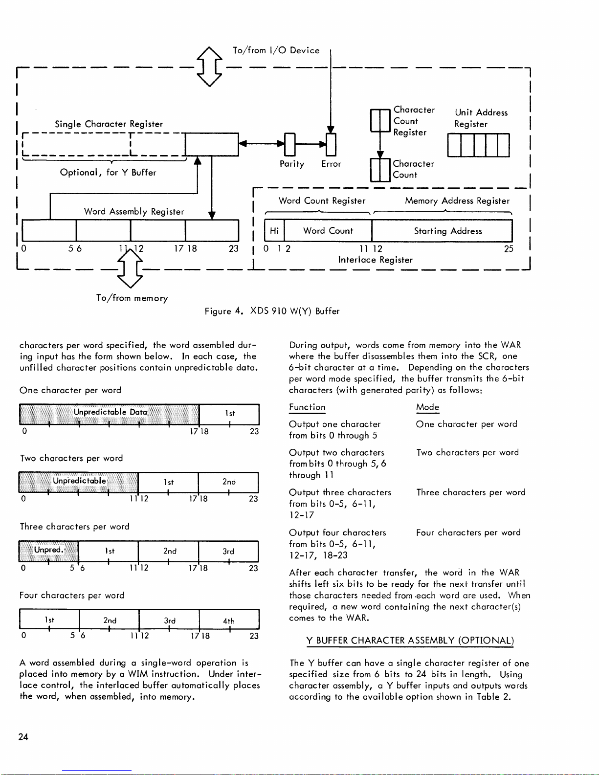
,------
------1
I
I
I r -
__
~~~_~h~~~~
IL
___________
I \ T
I 1
Optional,
I I Word
:~~t:.r
L____
for Y Buffer C t
__
-.-
____
..,
~
Parity
_________
Co~nt
Register Memory
Character
;::i~;er
Character
0:
_______ 1
Unit Address I
Register I
IIIIII
~ddress
Register I
I
II
I Word Assembly Register "
I
r-I-H-i
"'II--W-o-r-d-C-o-un-t---.----S-t-a-rt-i
lO
....
-_-_-=~-5~6~-=~-U.-.....1-2~~-~_1-7~1-~8-----~23-10-1
characters
ing
input
unfilled
One
character
per
word
has
the
character
per
To/from
form shown
positions
word
memory
specified,
contain
the
word assembled
below.
unpredictable
In
Figure
each
case,
4.
XDS 910 W(Y) Buffer
dur-
the
data.
2
__
During
where
the
6-bit
character
per
word mode
characters
~terl~~~2RegiS~
output,
words
buffer
disassembles them
at a time.
specified,
(with
generated
come
from memory into
the
parity)
n-g-A-d-d-re-s-s--"'" I
____
into
the
Depending
buffer
on
the
transmits
as follows:
2_5_J
the
WAR
SeR,
one
characters
the
6-bit
o
Two
characters
o
Three
characters
o 5 6
Four
characters
1 st
o 5 6
A word
placed
lace
the
assembled
into
memory by a WIM
control,
word, when
per
word
1112
per
word
1 st
I
per
word
2nd
I
during a single-word
the
interlaced
assembled,
buffer
into
1718
1 st
I
2nd
3rd
I
1718
instruction.
automatically
memory.
1 st
2nd
3rd
I
4th
operation
Under
I
I
is
inter-
places
23
23
23
23
Function
Output
from
Output
from
through
Output
from
12-17
Output
from
12-17,
After
shifts
those
required,
comes
The Y
specified
character
according
one
bits
bits
bits
bits 0 -5
each
left
characters
to
Y
BUFFER
buffer
Mode
ready
from
to 24
option
One
Two
Three
Four
the
for
.each
character
character
0 through 5
two
characters
0 through
11
three
0-5,
four
18-23
character
six
a new word
the
size
assembly, a Y buffer inputs
to
5,6
characters
6-11,
characters
, 6 - 1
1,
transfer,
bits
to
be
needed
containing
WAR.
CHARACTER ASSEMBLY
can
have a single
from 6
the
bits
available
character
characters
characters
characters
word in
the
next
word
are
the
next
(OPTIONAL)
bits
in
length.
and
shown in
per
word
per
word
per
word
per
word
the
WAR
transfer
character(s)
register
outputs
until
used. When
of
Using
words
Table
2.
one
24
Page 31

Table
2.
Y Buffer
Character
Assembly
Options
10
1 1
12
1
0 3
1:1:1:::I:I'I:I:I:!:::!'!:!:1
1 2
0
0
Input
2nd
13
I
12
13
)12
3rd
I I
)18
14
2nd
st
J6
4
I
2nd
I
)12
1
st
1
st
I
1
2nd
2nd
I
I
4th
23
23
23
23
II
I
I
I
I
1
st
I I
0
1
0
0
0
I
5 6
st
6 7
1
st
7 8
1
st
1
st
1
st
I
1
st
I
2nd
I
8 9
1
9
Output
I
1112
2nd
I
10
1011
11
12
1314
2nd
3rd
2nd
I
I
'1516
2nd
1718
3rd
2nd
I
I
4th
20
3rd
I
23
23
23
212223
23
I
No
character
Character
treats
the
truncated
A
buffer
Word
Count
Register (MAR).
for
an
interlaced
struction
of
the
word
starting
Transmission"
pages
33
EOM ENERGIZE OUTPUT M
023
ENERGIZE OUTPUT M (EOM)
struction
functional
input/output
troL in
assembly/disassembly
Register
contents
word.
INTERLACE
interlace
transmits to
count
address
and
PRIMARY
that
configurations.
the
sizes
of
contains
Register (WCR)
In
the
input/output
the
(that
of
the
and
"Programming
34.
INPUT/OUTPUT
02
I
operates
control,
third
IIII
8 9 101112
and
of
13 bits
the
Single
REGISTERS
set-up
interlace a data
is,
length
block.
Character
two
working
and
sequence
operation,
See
the
and
(OPTIONAL)
the
of
"Interlaced
INSTRUCTIONS
is a multipurpose
in four
internal
distinct
The modes
control,
fourth modes, EOM
occurs
with
Single
larger;
memory Address
the
Interlace
modes
are
the
Register as a
registers,
- EOM,
the
POT
word
block)
Register,
with
buffer
and
system
initiates
made
and
Block
control,
buffer
the
POT-
in-
up
the
23
in-
many
con-
and
controls
tems transmissions. Each
instruction
the
standard
Buffer EOM Instruc tions,
The
setting
format
of
EOM:
Bit Positions
10
a
II
a
1
1
An EOM in
as a
setup
or
other
in
this
ripheral
sired
character
and
its
binary
er
(as in
(as in forward
Execution
peripheral
non-buffer
configurations
assembler,
of
two
determines
11
a
1
a
1
the
buffer
or
preparation
peripheral
mode
specifies
unit
on
that
format. EOM
"connected"
data
transmission,
paper
or
of
such
unit
to
bits
the
activities
buffer,
peripheral
tape),
reverse
an
the
operations
of
has a mnemonic
META-SYMBOL (see
II
page
(la,
different
control
facility
the
buffer
the
and
directions
EOM
buffer.
such
the
frequently
28).
11) with in
modes for
Mode
Buffer
Control
Input/Output
Internal
System
the
allowance
the
also
Contro
mode
operates
for
data
using
the
to
be
operation,
also
detai
unit
the
direction
for
connects
EOM in this
Control
magnetic
as
special
used
EOM
recognized
II
Standard
the
instruction
the
operation
Control
I
essentially
transmissions
buffer.
used,
the
and
the
Is
to
the
buffer
use
of
BCD
or
not
of a lead-
of
operation
tape).
the
specified
mode
sys-
by
EOM
pe-
de-
or
can
25
Page 32

also
alert
tic,
buffer
An EOM in
vices
to perform
wi nd
magnetic
alert
peripheral
or
PARALLEL
EOM
can
10
to
12
bits
4095
words).
this
EOM
An
EOM
ables
the
can
prepare
arming
Interrupt
An
for a
bility
c
If
in
cution
completed.
EOM in
ial
system
an
any
of
given
is 15
interrupt
mode,
of
SKS
o 2 3
SKS
is a multipurpose
the
states
their
attached
internal
instruction
to
quire
terna I test,
special
the
Each
tions
(see
The
format
SKS:
and
all
buffers,
it.
system
SKS
tests
of
the
has a
"Standard
setting
determines
Bit Positions
10
o
o
1
1
the
interlace,
control
the
input/output
nontransmitting
tape
devices
OUTPUT (POT)
also
give
(for transmission
Without
can
also
in
the
internal
interrupt
the
system for
the
system
System.
the
system
installation
bits
or
designations.
occurs
no
acknowledgement
the
instruction
SKIP
40
I
and
responses
peripheral
external
providing a decision
devices,
It
operates
input/output
test.
buffer-oriented,
frequently
mnemonic
Buffer SKS
of
two
11
which
for
input/output.
and
upspace
that a PARALLEL
an
extension
disturbing
set
up
control
system. The
interrupt
control
and
32,768
during
following
IF
SIGNAL
IIII
test
of
indicators.
indicators,
in
four
In
the
used SKS
recognized
bits
(10, 11)
the
different
o
1
o
1
is
the
optional,
mode
directs
operations
the
pri
nter.
instruction
of
of
blocks
the
the
interlace.
mode
internal
the
selective
levels.
mode is
system. Addressing
combinations
the
execution
NOT
instruction
input/output
devices
and
distinct
unit
test, i nte
input/output
input/output
instruction
by META-SYMBOL
Instructions, " page
within
modes
Special
Input/Output
Internal
Special
follows.
the
word
of
associated
enables
control
arming
See
specially
for
can
occur
the
EOM has
SET
used for
as
well
SKS
is a "skip
transfer
and
systems
modes:
rna I
unit
the
of
operation
Internal
Test
System Test
buffers
as for
automa-
peripheral
such
It
INPUT (PIN)
count
from 1024
and
Section
these
of
an
unti I
capability
special
test,
test
functions.
configura-
instruction
Test
Unit
as
re-
can
This
from
buffer,
dis-
EOM
and
3,
coded
capa-
spe-
EOM
exe-
been
testing
and
testing
class"
that
and
mode,
29).
of
Test
de-
to
dis-
re-
in-
23
In
the
input/output
devices
magnetic
tape,
In
interrupt
breakpoint
Other
buffer
In
SKS
systems
The ENERGIZE OUTPUT M (EOM) in
mode
lects
format
directly.
tape
file-protect
the
internal
system is
configurations
ready
the
special
tests
signals
require.
addresses
the
desired
is:
switch
and
o
02
023
Bit
Designation
002
00
F/R
L/N
unit
test
mode,
These
include
unit
such
as
beginning
ring
present,
test
mode,
is
for
internal
of
BUFFER
and
connects
unit
2
I
8910111213141516111819
Octal
Position
0-2
SKS
enabled
set,
of
buffer
special
II
or
and
whether
this
SKS
error.
and
special
configuration
CONTROL
the
address.
3
ioI
°lt~l~
Octal
Value
002
3 4
3 o
4
o
4
4
o
2
testing
and
tests
disabled,
also
specified
The
4
Function
Bit
positions
contain
code
A
1-bit
alerts
Bit
positions
contain
the
buffer
Bit
position
the
direction
peripheral
erate.
forward
should
devices
erating
(octal
verse
Bit
position
whether
be
started
as
in
specifies a start
leader.
spec
leader,
be
used for a
pableofproducing
SKS
tests
indicators
of
tape,
end-of-file.
whether
whether
Overflow
perform
system
EOM
detailed
Y
for EOM.
the
di
as
the
buffer
buffer
5
w
IB
IcM
the
instruction
in
position
buffer
the
indicator
control
12
device
A 0
specifies
direction,
always
incapable
in
reverse.
4)
specifies
rection.
test
0 through 8
13
the
device
with a leader
paper
tape.
A 1
ifi es a
and
start
should
peripheral
in a
end
of
or
not
the
a
is
set.
tests
for
modes,
the
specific
control
and
instruction
6
7
Unit
I
9
interlace.
10
and
11
mode.
specifies
in
which
will
and
be
used for
of
A 1
the
specifies
should
A 0
with
(octal
2)
wi
thout
always
device
leader.
se-
23
for
the
op-
the
op-
re-
inca-
26
Page 33

Bit
Designation
Octal
Posi
tion
Octal
Value
Function
Bit
Octal
Designation Position
Octal
Value
Function
D/B
4
0
1
c/W
5
0
2
4,
6
Octal
Value
00
01
02 Type Input
03
04
Input
Function
Disconnect
Type Input
No.
No.
Type Input
No.
Paper Tape Input
05 Paper Tape Input No. 2
06
07
Card
Reader Input No. 1
Card
Reader Input
Bit position 14
the
character
o spec ifi es
specifies
a 1
format. A
BC
D format;
Binary
mat.
Bit positions
specify
characters
bled
into,
from,
word.
per
word
15
the
number
to
be
ordisassembled
each
transm
One
character
is
specified
(octal 0), two by
tal 2),
4) and four by
three
by 10 (octal
11
Table
1
2
3
No.
1
No.
2
specifies
for-
and 16
of
assem-
itted
by
01
(oc-
(octal
6).
3.
B 5
I/O
UNIT
00
Unit Address
Octal
Value
40
41
42
43
44
45 Paper Tape Punch
46
47
6 Bit position 18
6-7
Codes
Output
Function
Not
used
Type
Output
Type
Output
Type
Output
Paper Tape Punch
Card
Punch
Card
Punch
0
1
0
4
No.
No.
No.
Output
Output
Bi
t posi tion 17 spec i
the
buffer to
A 0
specifies
a 1 spec ifi es th e
the
direction
sion. A 0
1-bitspecifiesoutput.
a
Bit positions
fy
the
peripheral
to
be
used in
output
operation.
Table 3 for
codes
for
vices.
)
1
2
3
Output
Output
No.
No.
No.
No.
1
2
be
controlled.
the W buffer;
Y
specifies
of
transmis-
specifies
19-23
the
unit
address
peripheral
1
2
fi
es
buffer.
input;
specidevice
input/
(See
de-
10
11
12
13
14
15
16
17
Magnetic
Magnetic
Magnetic
Magnetic
Magnetic
Magnetic
Magnetic
Magnetic
20
21
22
23
24
25
26
27
Disc
Disc
30 Scan
31
Scan
32 Scan
33
34
Scan
Scan
35 Scan
36 Seen
37
Scan
Tape Input
Tape Input
Tape Input
Tape Input
Tape Input
No.
No.
No.
No.
No.
Tape Input No.
Tape Input
Tape Input
File
Input
Fi
Ie Input
Magnetic
Magnetic
Magnetic
Magnetic
Magnetic
Magnetic
~YA.cgnetic
Maanetic
-
'"
- - •
No.
No.
No
..
No.2
Tape
No.
Tape No.
Tape
No.
Tape No.
Tape
No.
Tape No.
Tape
f'~o.
Tane
No_
--1--.•
0
1
2
3
4
5
6
7
50
51
52
53
54
55
56
57
60
61
Magnetic
Magnetic
Magnetic
Magnetic
Magnetic
Magnetic
Magnetic
Magnetic
High-Speed
High-Speed
Tape
Tape
Tape
Tape
Tape
Tape
Tape
Tape
Printer
Printer
Output
Output
Output
Output
Output
Output
Output
Output
Output
Output
No.
No.
No.
No.
No.
No.
No.
No.
0
1
2
3
4
5
6
7
No.
No.
1
2
62
63
64
65 Incremental Plotter
66
67
0
1
2
3
4
5
t..
v
7
- -
70
71
72
73
74
75
7L
'v
77
Incremental Plotter
Disc
File
Output
Disc
Fi
Ie
Output
Magnetic
Magnetic
Magnetic
Magnetic
Magnetic
Magnetic
Magnetic
tv\agnetic
Tape Erase
Tape Erase No. 1
Tape Erase
Tape Erase
Tape Erase
Tape Erase
Tape Erase
Tape
Erase
Output
Output
No.
No.2
1
No.
No.
No.
No.
No.
No.
t'-Jo.
0
2
3
4
5
L
0
7
No.
No.
1
2
27
Page 34

IN
PUT/OUTPUT
CONTROL
EOM
STAN
DARD
BUFFER
EOM INSTRUCTIONS
in
EOM
peculiar
paper,
so
Output.
the
to a given
or
controls
o
023
Bit
Designation
002
01
I/o
skip
to format
certain
02
Octal
Position
0-2
3 4
3
control
device
buffer
2
8
controls
such
channel
functions
3 4 5 6
9101112
Octal
Value
002
various
as
rewind
on
the
such as
16171819
Function
Bit
positions 0 through
contain
code
A 1
alerts
tached
specified
Bit
specify
of
the
for
in
bit
the
to
positions
I/O
EOM.
operations
tape,
printer.
Terminate
instruction
EOM.
position
interlace
the
buffer
by
bit
10
control
space
It
Unit
I
17.
and
al-
7
9
at-
11
mode
23
8
Severa I EOM
These
have
separate
ALC
EOM
instructions.
0
050000
o 2 3
ALC 0
does
end-of-word
I/O
ALe 1
EOM
Affected:
DSC
EOM
alerts
not
disturb
operation
050100
W(or Y)
0
0
function
standard
ALERT W BUFFER
configurations
assembler-type
02
I
8 9
the W buffer
the
interrupt
terminates.
ALERT Y BUFFER
Interlace
DISCONNECT W BUFFER
buffer
is
interlace.
in
any
inh
ibited
way,
02
I
have
mnemonics
50000
I
This
except
unti I the
00000
standard
and
instruction
that
interlaced
o
02
50100
Timing: 1
uses.
are
23
the
23
Function
B
I/O
UNIT
I/O
An
alert
EOM
count
bits
When
bits
12
terminates
to
"scanll.
control
and
equal
18-23
4-5
5
6
6-7
EOM
the
to
are
outputs
0
1
0
4
occurring
POT sets
bit
positions
all
zeros, a 1-bit
or
converts
Bit
positions
ify
control
each
peripheral
Bit
position
the
buffer
to
ed.
A 0
specifies
buffer;
Y
Bit
the
mission. A 0
input;
put.
Bit
fy
to
output
Table
address
ripheral
the
buffer.
position
direction
a 1
positions
the
peripheral
be
used in
operation.
3 for
between
high-order
22
and
magnetic
a 1
specifies
specifies
codes
devices.
an
23
in
bit
12-16
peculiar
device.
.17
specifi
be
controll-
18
specifies
of
trans-
specifies
19-23
device
the
input/
I/O
and
for
pe-
)
interlace
interlace
of
the
position
tape
inputs
spec-
to
es
the
W
the
out-
speci-
(See
unit
EOM.
DSC 0
ditionally
of
vice.
buffer.
ready
OSC
EOM
Affected:
TOP
EOM
disconnects
sets
whether
DSC
This
and
or
disconnects
clears
1
0100
W(or
0 TERMINATE OUTPUT
014000
the W buffer.
the
unit
not
the
buffer
instruction
the
error
DISCONNECT Y BUFFER
Y)
Buffer, Error
02
I
The
execution
disconnect
character
the
peripheral
terminate a noninterlaced
TOP
1
EOM
014100
.Affected:
of
this
instruction
when
the
buffer
of
the
word
in
device.
TERMINATE OUTPUT
W(
or
Y)
Buffer
This
address
any
unconditionally
register
is
currently
device
indicator.
Indicator
connected
14000
I
causes
delivers
the
word
assembly
TOP
must
always
buffer
output
instruction
to
00
regardless
addressing a de-
to
the
makes
the
o 02
Timing:
ON W BUFFER
the
buffer
the
last
specified
register
be
used to
operation.
ON Y BUFFER
o
02
Timing: 1
uncon-
buffer
00100
23
to
to
14100
28
Page 35

ASC
EOM
0
012000
ALERT
TO
STORE ADDRESS
IN W BUFFER
Bit
Designation
Octal Octal
Position
Value
Function
o
2 3
o
This
instruction
Option)
struction
ory
address
in
no
other
section,
ASC
and
er.
The
ASC 0
PIN
When
the
effective
struction
Bit
o
through
9
02
I
8 9
(available
alerts a PINabie
that
follows
register.
way.
See
for a
detai
led
PIN
determine
two
instructions
M
program
memory
contains:
Pos
iti
executes
location
ons
8
through
23
with
interlace
can
store
This
instruction
Direct
discussion
the
are
designated
Contents
Zero
Contents
Memory
the
the
Parallel
current
written
these
of
Address
12000
I
Memory
so
that
contents
affects
Instructions,
of
PIN.
status
together:
two
instructions,
by
the
W buffer1s
Register
Interlace
the
PIN
of
the
the
buffer
of
the W buff-
PIN
in-
mem-
this
the
in-
23
xxxx
STANDARD
BRTW
SKS 021000
BRTY
SKS 022000
If
the
buffer
is
struction,
quence
buffer
periphera I unit,
tion
BETW
SKS 020010
and
is
active,
in
sequence.
the
executes
4-7
BUFFER
W
BUFFER
Y
BUFFER
ready
computer
or
in
the
computer
W
BUFFER
to
the
the
READY
accept
skips
Bit
23
of
computer
the
Selecting
test
to
condition
the
SKS
READY
TEST
a new
the
following
process
executes
ERROR
TEST
positions
specify
these
test
causes
skip
se I ected
INSTRUCTIONS
TEST
12
the
tests
cause
to
skip
condition
more
the
only
when
exists
tests.
through
test.
than
computer
040
040
input/output
next
instruction
instruction.
of
disconnecting
the
next
040
the
when
is
skip
on
all
21000
22000
in-
in
If
the
a
instruc-
20010
Each
true.
one
of
se-
ASC
1
EOM
012100
Affected:
The SKIP IF
test
mode tests
nstructi
i
on
o
Bit
Designation
040
010
ALERT
W(or
SIGNAL
format
40
I
Octal
Position
0-2
3
TO
Y)
Interlace
INTERNAL
the
indicators
is:
234
STORE ADDRESS
TEST
SKS
NOT
SET
(SKS) in
in
the
selected
Octal
Value
040
2
Function
Bit
positions 0 through
contain
code
for SKS
Bit
positions
contain
mode
selection
IN Y BUFFER
o 02 12100
Timing: 1
the
internal
buffer.
5 6 7
XXXX
I
the
instruction
10
and
the
internal
11
test
The
23
8
BETY
SKS 020020
BETW
(BETY)
er.
If
the
error
skips
the
next
following
the
Affected:
SKS in
the
vidual
contained
instruction.
computer
(P) Timing: 1
the
peripheral
test
in
o
023
Y
BUFFER
tests
detector
instruction
executes
INPUT/OUTPUT
input/output
devices
condigurations
Section
2 3 4 5 6 7
the
8 9
error
If
the
in
6.
ERROR
detector
has
not
in
sequence
the
error
next
UNIT
test
mode
the
system
for SDS
10
1 1
12 16 17
TEST
in
been
set,
and
detector
instruction
TESTS
tests
directly.
peripheral
the
selected
the
executes
has
in
the
condition
18
04020020
buff-
computer
the
been
sequence.
if
no
skip
2
if
skip
The
indi-
devices
set,
of
are
23
29
Page 36

Bit
Desi9nation
040
Octal
Position
0-2
Octal
Value
040
Function
Bit positions 0
contain
code
the
for S
instruction
KS
through
MEMORY
from a
W
buffer
8
eral
specified
to
device
INTO
W (MIW)
be
output
connected
memory
to
to
causes
location
the
currently
the
buffer.
a word
and
operating
to
be
placed
taken
in
periph-
the
3
Unit
Tests
B 5
Unit
Address
3-4
6-7
SINGLE·WORD
Using
the
Wand
data
words
between
der
the
direct
control
plish
this,
the
program first
peripheral
tion;
mission.
instruction,
buffer.
tions
For
the W buffer, W INTO
word
VI
buffer
location
device
then
the
program performs
One
of
ENERGIZE OUTPUT M
The program performs
with
two
instructions
from a
peripheral
and
placed
without
0,
Y
buffers,
memory
of
single
with
an
the
configurations
transmission
directly
disturbing
Central
Processor
Bit
position 9 contains
Bit positions 10
zero.
and
11
contain
unit
test
mode
Bit
16
1
Bit
the
A 0
er;
Bit
23
dress. (See
positions
select
position
buffer
specifies
a 1
positions 18
specify
12
the
17
to be
the Y buffer.
the
Table
TRANSMISSION
a program
and
peripheral
instructions.
alerts
energize
the
the
direct
associated
MEMORY (WIM)
in
the
any
internal
can
the
buffer
or
"alert"
di
rect
control
of
the
multipurpose
(EOM),
control
with
to
be
taken
specified
registers.
Memory
devices
each
the
I/O
selection
through
test.
specifies
activated.
the W buff-
through
unit
ad-
3)
transmit
un-
To
accom-
and
the
instruc-
trans-
alerts
the
operabuffer.
causes
a
from
the
memory
o
I/O
YIM
and
MIY
for
the Y buffer.
SIGNAL
ing
devi
MIW
MIW transfers
cation
until
word.
The
device
se
lects
control
peripheral
Affected:
NOT
error
indicators
ce
indicators.
into
the W buffer.
the
buffer
buffer
must be
by a
the
buffer,
functions
device.
W Buffer Timing: 2 +
Device
instructions
The
SET
(S
and/or
MEMORY
the
contents
is
empty
connected
previous
the
and
Central
Processor
function
general
KS), provides
buffer
unit
connects
test
for
testing
INTO W BUFFER
of
the
The
centra
and
ready
to
the
control
address,
the
Memory
in a simi
instruction,
the
faci I ity for
various
WHEN
effective
I processor
to
accept
desired
EOM
instruction
and
a
II
buffer
to
lar
manner
SKIP IF
peripheral
EMPTY
memory
waits
the
data
peripheral
appropri
the
desi red
test-
lo-
that
ate
wait
I/O
Device
30
MIY
&..-L-1o1
0
X.....I.......iI
1---+\0--+1
MEMORY
° 1 2 3 8 9
MIY transfers
cation
unti I the
word.
Affected:
into
the
contents
the Y buffer.
buffer
is
empty
Y Buffer
INTO Y BUFFER
I.....&-.-I
-+---+-M--+----+-----.l11
10
I
of
the
effective
The
central
and
ready
processor
to
accept
Timing: 2
WHEN
memory
the
EMPTY
lo-
waits
data
+
wait
23
Page 37

WIM W
32
I
WIM
transfers
effective
until
the
memory
buffer
word.
BUFFER
the
is
contents
location.
full
and
INTO
of
The
ready
MEMORY
WHEN
M
I
the W buffer
central
to
processor
deliver
the
into
data
FULL
the
waits
23
word
assembly
shift
takes
fers
the
contents
bits
of
the
the
SCR, a seventh
If
a
parity
trol
panel
error
does
in
the
computer
and
reset
place
WAR.
error
ERROR
not
this
register
through
of
When
occurs,
indicator
stop
that
bit
at a later
the
parity
the
allow
(WAR)
and a 6-bit
the
WAR. This
SCR
into
the
character
bit
is
the
parity
is
lighted.
computer.
the
time.
the
least
checked
bit
Facilities
program
circular
process
significant
is
transferred
by
the
is
set
and
Note
are
to
interrogate
that
left
trans-
to
buffer.
the
con-
such
an
provided
Affected:
(M)
YIM
I
101+1
30
o 1 2 3
YIM
transfers
fective
unti I the
word.
Affected:
Using
structions
tween
trol.
buffer
this
mitting
The
device
rupt,
gram;
the
memory,
interrupt
ready. A service
MARK PLACE (BRM)
terrupt
contains
that
An
(see
ies
counter
sets
As
SCR. In
the
ed.
innllf'
•••
memory
buffer
the
the
Between
is
ready
delay
or
interrupt
to
and
this
buffer
the
location
location
the
can
execute
input/output
Primary
the
number
(CC),
the
single
soon
as
addition, a signal
data
to
With
,.1,...+,...
,....--
""""""."" • ....,....,,...., , ••
(M)
SINGLE-WORD
buffer
(MIW,
buffer
is
normally
receiving
system
be
used
then
eliminates
empties
End-of-Word
instruction
Input/Output
the
the
the
11"\1"\r'\
Y
BUFFER
I
the
contents
location.
is
full
control
WIM,
and
data
to
perform
in
to
continue
or
notifies
routine
processing
immediately
operation
of
characters
clears
character
first
character
buffer,
arrival
+h", ,rJ:l :
- -
INTO
The
and
EOM
etc.),
memory
words,
the
that
the
the
previously
allows
the
transfer,
the
central
fi lis
during
interrupt
the
is
instruction
(MIW
is
Instructions).
the
error
register
indicating
of
this
..
........ " 1.;1
MEMORY
of
the Y buffer
central
ready
to
del
OPERATIONS
and
input
data
words
under
direct
the
computer
transfer.
buffer
requested
the
program
to
processing
processor
the
to
program
entered
the
via
in
the
interrupt.
or
WIM,
without
started
per
by
word
switch
(SCR)
arrives,
is
sent
from
that
signal,
"'I"\nl"\o",+o,.l
......
....,
which
••••
""
.......
""',..
Timing:
WHEN
M
into
processor
iver
Timing:
or
output
transfer
program
waits
The
is
actively
to
connect
enable
in
the
tie-up.
transfer
the
corresponding
that
a BRANCH
appropriate
Th
for
example)
computer
executing
EOM
into
the
(E)
and,
to
receive
it is
stored
the
source
the
SCR is
closes
"0
..
:,...11"
..J"'II""I'1 • ....,
the
the
3 +
until
cause
data
the
main
from
the
buffer
is
routine
also
character
for
+1"\
3 +
wait
FULL
ef-
waits
data
wait
inbe-
con-
of
trans-
word.
the
inter-
pro-
When
or
AND
in-
tie-up.
EOM
input,
inputs.
in
of
load-
the
+ho
Illv
23
the
to
cop-
the
As
soon
as
the
contents
to
the
WAR
the
contents
decremented
are
still
next
character.
SCR
and
above.
positions
contents
sitions
zero,
it
that
forces
word
of
of
the
abled
(see
An
alternate
tape
and
tape
generates a second
end
of a block.
gram
may
complete
er
is
ready,
output
The
input/output
actly
analogous
ated
rather
loop
synchroniz
is
lost.
the
is
to
the
input
the
output
character
character
Data
can
WAR
and
correct)
be
entered.
magnetic
will
be
been
loaded
has
been
empty.
rence
of
The W
f..? "nn
"""_,...,vv
by
one.
greater
than
When
the
WAR
The
information
of
the
WAR
of
the
SCR
of
the
WAR.
generates
the
computer
information
buffer,
providing
Section
method
magnetic
During
ascertain
by
testing
the
transfer
operation
may
to
than
checked.
ing
During
source
input
indicating
buffer.
device
into
the
be
lost in
the
SCR
at
the
time
If,
for
tape
unit,
lost.
Similarly,
into
used, a position
In
either
the
error
buffer
can
,..h,...
..
,...r+",
____
.. " r'\"'''
1_,..,
_1,
If
zero,
the
repeat
are
are
When
an
interrupt
he
Id
3).
may
tape.
when
the
be
system
input.
system
th
is
is
used
character
one
can
both
that
example,
information
the
WAR
case
the
and
lights
operate
"",rl"\n,.l
,...._ •
..,
__
of
the
SCR
have
of
the
character
the
new
contents
the
buffer
next
character
the
that
shifted
shifted
the
shifting
was
operation
in
the 6 right-hand
left 6 bits,
into
the 6 right-hand
character
pulse
to
into a subroutine
in
the
word
assembly
that
the
interrupt
be
used
with
In
these
cases, a gap
interrupt
the
the
status
is
complete
input
transfer
of
which
process
the
buffer.
and
initiated.
outputs
takes
During
data
Parity
As
noted
is
used
the
that
the
output, a signal
to
time
in a
in
this
previously, a closed-
to
assure
form
data
the
loading
register.
of
two
ways.
be
full
(if
another
character
the
source
cannot
during
output,
by
the
on
the
magnetic
computer
the
ERROR
up
to a maximum
Iln,.l",
"'
•• _ ...,.1--.
time a II
detects
.. rl"\l'Y'Ir'\II+O ..
__
been
counter
of
will
wait
arrives,
counter
the
computer,
to
system
punched
signifies
the
of
information
another
manner
case
that
of a signa
has
During
the
program
is
of
data
be
delayed
if
data
previous
tape
the
indicator.
frequency
t",....VI'-.
sh
if
this
for
described
and
handle
register
paper
on
main
If
the
is
gener-
no
been
of
each
input,
ready
has
will
occur-
"'1"\1"\+
","V
••
ted
in-
are
counter
the
the
bit
the
new
po-
reaches
the
is
en-
the
the
pro-
is
buff-
input/
ex-
data
I from
sent
from
the
is
not
to
is a
and
not
data
be
..
",1
'IVI.
of
31
Page 38

Input Termination
When
the
end-of-record
buffer,
device,
and
buffer
cator
still
in
characters
End-of-Transmission
is
to
End-of-Word
word.
WIM
number
of
puter
either
if
WIM
had
safe
disengaged
When
Transmission
is
to
system is
the
buffer
generates
the
buffer
logic
is
be
in
the
input
disconnected,
the
least
The
instruction
of
the
number
word,
the
they
were
instruction,
been
to
issue
the
enabled. A special
test
the
is
then
is
reset,
maintained
the
word
record
assembled
and
significant
interrupt
partial
after
characters
of
characters
then
the
last group
not
previously
transferred
one
WIM
without
buffer
automatically
interrupt
buffer
not
being
or
for
signal
automatically
an
End-of-
ready
for
except
and
register.
was
into
Interrupt
zeros
word
in
word
of
zeros
to
hanging
ready
employed.
that
the
last word of
If
not a multiple
each
is
are
positions
is
not
generated
can
be stored in memory by a
the
buffer
the
input
assembled
remaining
characters
transferred
if
the
memory. In
instruction
up
is
actuated
SKS
instruction
is provided
is
detected
disengages
Transmission
another
the
computer
generated,
automatically
of
has
last group
the
disengages,
operation.
the
state
the
number
of
the
word,
the
last
for this
disengaged.
record was a
into
in
the W buffer
from
the
to
memory by a
either
after
the
computer.
if
the
interrupt
(BRTW
if
the
by
the
from
Interrupt,
of
error
input
of
characters
number
then
the
buffer
forced
word.
partial
multiple
each
com-
input
of
characters
case,
it
buffer
an
End-of-
or
BRTy)
interrupt
W
the
The
indi-
wi
II
of
an
in-
The
If
the
is
device,
is
has
system
tape, a tape
disengaged.
buffer
system
nal
is
ready
is
enabled,
is
generated.
INTERLACED
Using
the
Wand Y buffers,
blocks of
interlace
W Buffer
data
control.
gap
is
generated
After
the
for
another
an
to
and
(See Figure
Interlace
o
I/O
Interlace
before
output
End-of-Transmission
from
Device
unit
operation.
BLOCK
TRANSMISSION
a program
core
the
is
disengaged,
If
storage
5.)
Central
Processor
Interlace
Central
Processor
tape
the
interrupt
interrupt
can
transmit
under
Memory
Output
Memory
unit
buffer
is
the
sig-
Scan
During
vert
(see
is
is
that
an
still
tape
continues.
tape
rupt,
interrupt
scanned
Output
When
formation
should follow this
instruction.
sent
matically
the
input
the
operation
Magnetic
operating
shifted
it is
End-of-Word
moving.
within
wi
and
to
status
in
into
full.
500
If
II
stop,
disconnect
occurs,
(not zeros)
Termination
the
computer
of
an
The last word in
the
output
disengage
of
from
Tape
the
the W buffer
When
If
no command is
generate
output
the
magnetic
to a scan
Input/Output).
scan
interrupt
a read
microseconds,
the
are
has transferred
with
device
from the
error
tape
by a
mode,
but
the
end-of-record
is
generated
or
scan
an
End-of-
the
buffer. When
last four
held
record
a TERMINATE OUTPUT (TOP)
and
indicator.
the
proper
character
the
buffer
command is
the
reading
given
in this
Transmissioo
characters
in
the
W buffer.
the
to
the
the
buffer
then
the
device,
In
the
program may
EOM
instruction
When
the
W buffer
after
character
never
(gap)
is
while
the
sent
or
scanning
interval,
the
End-of-Word
of
the
last word
W (or Y)
buffer
maintaining
will
case
buffer,
be
wi
of
magnetic
con-
signals
detected,
tape
is
to
the
the
inter-
record
of
in-
it
properly
II
auto-
only
Control
W Buffer
Figure
interlace
The
the W buffer
26-bit
two
bit
ed
by
MAR
of
bits
mode)
now be
fering
interlace
parts, a 12-bit
memory address
with a 24-bit
execution
and
10 bits of
the
WCR
are
required,
instruction.
copied
with
I/O
5.
control,
previously
register.
word
of POT
permit
they
into
other
activities
Device
Interlace
which
described
word
count
register
taken
instruction
the
WCR. The
the
counter
are
An
entire
or
read
Interlace
Output
is
optional
and,
This
register
register
(MAR). The
from the
which
two
to
reach
set by
an
block
of
out
of memory
of
the
computer.
Input
and
Input
equipment,
additionally,
is
divided
(WCR)
computer's
loads
high-order
EOM
information may
register
the
4095.
(I/O
without
and a 14-
is
If
control
uses
a
into
load-
memory
14-bit
bits
these
inter-
32
Page 39

The
WCR
holds
the
number of words
output
number
MAR
is
Because
to
Aswith
output
time
acters
the
new
When
not
At
character
halted.
ory
portion
ed,
ed
operations
that
ing new information for
operation
and
switch.
operation.
of
contains
to
be
placed,
of
any
memory
single-word
operation.
into
are
character
character
the
initiated.
the
end
The
location
of the
the
computer
by
one,
during this
regardless
words
the
or from
it's
14
location.
the
single
shifted
counter
is
entered,
character
Instead,
of
the
counter
contents
specified
interface
and
the
require
interval
occurs
of
For
that
initial
bit
operations,
Information flows
character
into
counter
memory
has
is
started
WCR
16
regardless
the
position
input
the
WCR
the
computer
address
which
capacity,
the
(CC) is
a number of
reached
of
the
by
the
register.
is
microseconds.
the
the
into
information
the
EOM
register
word assembly
decremented
and
parity
reaches
cycle
during
zero,
WAR
are
present
After
again,
reduced
buffer's
next
word.
of
the
of
the
in a block
holds
the
maximum
wi
II
accept.
which
information
is
to
obtained.
MAR
permits
initiates
one
(SCR),
errors
zero
other
the
stored in
contents
the
MAR
by
It
SCR
HALT
RUN-IDLE-STEP
the
character
the
register
each
are
an
interrupt
events
which
the
computer
of
this is
accomplish-
is
increment-
one.
All of
should be
can
be
The
interlace
indicator
of
The
access
input/
at
char-
(WAR),
time a
sensed.
occur.
buffer's
is
the
mem-
the
MAR
these
noted
accept-
status
an
a
02
,
1000X
23
Bits
22
and
23 of this EOM
significant
to
bit
capabi I ity
(03777),
the
values
is
Before
gages
must be
interlace
ster
without
the
same
the
I/O
EOM
field
The
instruction
or ALC) may be
significant
instructions
the
POT
bits of
positions 0
is
3071
1,
PROGRAMMING
the
execution
the
interlace,
"alerted".
may
buffer
device,
{coded
of
the
bits of
instruction
the
and 1 of
thus
extended
(05777),
2,
or3,
the
The EOM
be
ALC
otherwise
control
with a I-bit
with
an
instruction},
following
another
the
be programmed
word
respectively,
of
(which
affecting
asterisk
WCR. It
contain
count,
the
from 1023 (01777)
or
4095
THE
the
appropriate
EOM
the
EOM
between
and
WCR. The
(07777) words by using
INTERLACE
POT
instruction
instruction
alerts
the
the
buffer)
that
connects
in
bit
position 9 of
prefixed
alert
EOM
to
set
is
important
the 2 most-
are
transmitted
word-count
forX.
REGISTER
which
interlace
that
interlace
or
the
to the
(buffer
the
two
that
the
alert
to
2047
en-
register
alerts
regi-
it
may
buffer
the
operand
control
mostno
EOM
and
the
be
to
other
After
the
next
word has
counter
stored in
of
unti I
input,
The system
to
word.
The
the
o
The word
the
of
output
of the
sitions
positions
ing addressing of memory
(16,385)1.
second
instruction,
will
the
interlace
the
unti I a
input
data
POT
Word
I I
data
word,
the
interlace
of up
input/output
10-23
EOM
have
gone
the
new address
register:
interlace
outputs
and,
word
instruction
count
12-25
For word
register's
gap
or
end
data
simi
larly,
transmitted
has
Count
and
to
1023 (01777) words. The
of the
is
used
and
I
'9
10
is
right-justified
is
transmitted
register
operation
data
of
the
interlace
counts
between
has
the
been
assembled,
to
zero
again.
specified
this
WCR
of
record
in a manner
requires
to
the
following format.
(WCR),
word,
locations
of more
following format:
by
procedure
reaches
is
encountered.
exactly
16
microseconds
the
interlace
Starting
, , ,
in
bit
to
bit
providing
is
right-justified
and
is
register
0 through 037777
than
the
alert
the
transmitted
EOMand
the
character
This word
MAR
wi II
continue
zero
analogous
register
Address
positions
positions
for
starting
(MAR),
1023
will
portion
or,
on
per
by
0-9
2-11
input/
address
in
bit
to
provid-
words,
the
POT
be
23
of
po-
bit
The
next
instruction
which
sets
the
sets
the
MAR,
has not
EOM,
out
ing
buffer
1.
a
been
previously
it
can
be
disturbing
sequences
operation,
RPT
*0,
1,4
(buffer
EOM 01000X
POT WORD
control)
must
be
least-significant
and
started
the
can
engages
interlace,
be
the
started
after
used
to
Alert
the
buffer
operation
Transmit
tions
22
tion
to
(If
this
bits 0 and 1 of
zero
.)
Transmit
tions
0-9
bit
positions
transmit
tions
10-23
bit
positions
lace
register
the
End-of-Word
the
POT
instruction,
portion
interlace.
with a buffer
the
Thus,
initiate
interlace,
to
the
at 4 characters
the
and
bits 0 and 1 of
instruction
the
of
the
of
POT
instruction
either
an
device
contents
23
of
the
contents
location
2-11
contents
of
location
12-25
(MAR),
interrupt.
interlaced
is
WCR
of
of
the
WCR,
If
the
buffer
control
with-
of
the
follow-
connect
and
start
word
of
bit
this
instruc-
the
omitted,
wi
II
of
bit
WORD to
the
WeR,
of
bit
posi-
WORD
the
inter-
and
inhibit
the
the
posi-
WC
be
posi-
R.
to
33
Page 40

2. EOM *
(or ALC)
EOM
OlOOOX
Alert
the
interlace.
Set 2 high-order
bits
of
WCR.
automatically
rupt
signal
returns
to
normal,
disengage,
is
generated,
an
and
single-word
End-of-Transmission
the
End-of-Word
operations.
interrupt
inter-
POT WORD
RPTO,1,4
The
second
ually
single
Terminating
If
the
word
input
record,
engage
rupt
and
tion.
words in
buffer
of-record
rupt
not be
the
characters
This
out
If
record,
Then
buffer
in the W
ated.
program
into
up
let
words
er
SRR).
er
in a
disconnects
Terminating
When
eration,
sent
word
sent
simultaneously,
signa
I is
the
End-of-Word
If
the
the
(UAR) both
is
is
generated,
stored
record
last,
"hanging
the
word
the
the
interlace
continues
buffer,
If
the
can
memory by
the
interlace
the
interlace
to
memory; or
(DSC) or
If
the
continues
character
the
the
by
the
count
out
the
method
step
through
Interlaced
count
is
both
actuated
word
count
input
detected.
in memory if
is
not
an
per
word
partial
interlace
word may be
up"
count
interlace
to
an
interrupt
then
single-word
again
register
skip
the
remainder
to
input
rate
the
buffer.
Interlaced
terminate
interlace
reaches
last
Set
10
low-order
MAR,
and
inhibit
interrupt.
Connect
ber 1 and
characters
allows
Inputs
equal
the
interlace
if
interrupt
record,
automatically
The End-of-Transmission
but
the
integra I mul
specified
the
computer.
is
less
register
automatically
input.
End-of-Word
system
store
that
without
the
remainder
of
characters
error) unti I
Outputs
register
output
register
zero.
word,
the
buffer
start
per
the
computer
the
sequence
to
the
number of words in
and
the
End-of-
the
interrupt
returns
is
greater
the
last
the
than
When
transfer
program
the
When
the
than
interlace
disengage
characters
number of
tiple
by
the
stored
the
number of words in
word
disengages,
the
interrupt
is
enabled,
word
and
transmission; or it
disturbing
the
can
of
the
record
into
an
end
is
control
command
to
the W buffer
the
buffer
bits
of
WCR,
the
End-of-Word
to
device
the
operation
word
operator
of
instructions.
the W buffer
Transmission i
system
to
of
buffer
with
count
next
following
word
disconnect
record
is
the
of
I ing
buffer
and
is
normal
the
number of
register
when
received
characters
the
number of
control
a WIM
reaches
but
word
signal
the
interrupted
can
the
buffer
and
(SRC or
ignored-,
SCR
(resulting
record
an
output
is
automatically
after
has
the
interlace
set
num-
of
4
to
man-
the
dis-
nter-
enabled,
opera-
and
the
the
end-
inter-
wi
II
in
EOM.
with-
the
zero.
the
W
is
ready
is
actu-
words
set
and
following
the
buff-
the
buff-
signa
I
op-
the
properly
DIRECT
EOM
and
SKS
instructions
operations
tions.
Two
PARALLEL
to
be
or,
inverse
tor
to
cution
sent
output
data
becomes
transmits a
the
same time
places
without
puter
the
ready
During
processor transmits a
alerting
comes
tra I processor,
peripheral
cution
external
Special
of
control
central
PIN or
this
specific
quired
all
special
standard
EOM
POT transfers
location
up,
special
If
the
the
priority
tion
transmit
the
interrupt
no
computer
like
they
instructions,
INPUT
presented
be
stored
of
a POT or PIN
to
the
operation.
word as soon as
operational
the
disturbing
waits
the
it
operationa
of POT unti I
device.
system
processor
POT
requirement.
address
word.
peripheral
activates
specified.
the S KS
device
ready
can
occur
or
in
Iy,
cause
in
peripheral
ready
signal
presenting
data
word
during
signal from
execution
to
receive a data
I,
wh
device.
requirements
information
and
preceded
and
Thus,
systems as
and
24
bits
instruction
after
signal
interrupts,
as
soon as
receive.
persists through
hang-up
(PIN),
any
This signal
any
the
ich
The EOM
PARALLEL
control
PARALLEL
parallel
signa
core
device
it
is
during a
into a specified
arithmetic
execution
the
of
signal
it
transmits a
re leases
The
computer
it
rece
or
the
by
the
the
they
equipment
alerts
to
To
avoid
the
from
the
Since
occurs.
INPUT/OUTPUT
control
single-word
OUTPUT (POT)
cause
anyword
at a peripheral
Is
sent
memory
instruction
involved
tells
operational.
read
to
the
central
its
data
external
a POT
EOM
or from
can
the
instruction,
to
word.
the
ives
the
demand
data
be
special
the
activating
alerts
PIN or POT transfers
and
do
in
operations.
the
special
a possible
test
EOM
but
external
para
Ilel
the
externa I device
the
ready
the
parallel
to a periphera I connec-
causes a signal
the
or PIN
word.
registers.
of PIN until
device.
the
When
ready
data
waits
ready
transferred
external
the
PIN/POT
interlaced-W
the
the
prior
input/output
POT or PIN
input/output
buffer
and
in
core
connector,
location.
in
device
When a device
processor
memory
peripheral
signa I
during
that
system
device
effective
ready
to
device
signal
The
the
input/
to
operation,
The
computer
location
The
it
the
the
device
to
word
the
signa
I from the
complete
between
devices.
EOM
satisfies
device
the
operate
buffer/
That
and
memory
computer
signal
the
PIN/POT.
sets
is
initiating
execution,
opera-
memory
exe-
to be
send its
while
com-
receives
central
device,
be-
the
cen-
to
the
exe-
words
re-
is,
the
the
hang-
of
one
opera-
able
The
in
the
of
it
at
the
by
PIN/
to
34
Page 41

PIN
PARALLEL
INPUT
EOM
ENERGIZE OUTPUT M
Ilolxlol
o 1 2 3
PIN
stores
the
effective
Affected:
POT
Ilolxlol
o 1 2 3
POT
transmits
cation
vice.
Affected:
EOM
output
vices.
signal
external
a
tests
connector
and
15-bit
for
in
parallel
SKS
control
One
of
approximately 8 microseconds
connector
address
the
and
33
I
the
memory
(M)
Externa I Device
I [ I
8 9
contents
location.
PARALLEL
the
contents
to
24
10
of
OUTPUT
output
SINGLE·BIT
instructions
and
testing
configuration
and
also
for
the
destination
presence
skips
of a similar
accordingly.
M
I
24
input
lines
in
parallel
Timing: 4 +
M
of
the
effective
lines
of
memory
an
external
Timing: 3 +
INPUT/OUTPUT
also
perform
for
special
of
EOM
provides
single-bit
or
standard
transmits a single
duration
the
connector
of
this
signal.
signal
on
an
in
wait
lo-
de-
wait
input/
de-
to
an
with
SKS
external
23
23
02
89
Bit
positions 3 through 8 contain
code.
Bit
positions
Bit
positions
field
that
Bit
positions
tem
address
Affected:
Execution
dress
field
lection
device
the
next
If
there
skipped
The SKS
responding
format.
SKS
10
and
12
through
specifies
0,
1,
bits.
Special
of
an
SKS (system
of
the
SKS
of
special
is
supplying a set
instruction
is no
and
system
signal,
the
bit-set
SKIP
system
following
test
11
the
and 9 are
Device
instruction
in
sequence
the
format
being
IF
SIGNAL
101112
contain
23
contain
special
test
devices.
signal
next
instruction
is
identical
the
EOM
the
system mode
the
system
reserved
mode)
causes
to
be
presented
If
the
to
the
central
from
the
instruction
is
as
follows
to
the
NOT
SET
instruction
indicator.
12-bit
address
destinations.
for
special
Timing: 1
the
15-bit
to
the
addressed
processor,
SKS is
executed.
in
sequence
executed.
with
each
system
EOM
23
sys-
ad-
col-
external
is
cor-
Operating
ENERGIZE OUTPUT M (EOM)
NOT
missions.
Execution
microsecond
ble
32,768
SET
in
the
(SKS),
of
an
signal
signal
system
provide
EOM
destinations.
mode,
single-bit
(system mode)
to
be
transmitted
the
and
SKIP
input/output
two
instructions,
IF
causes
to
one
SIGNAL
trans-
an
8-
of a possi-
Affected:
(P)
40
I
Timing: 1
23
if
no
sk
ip
2
if
skip
35
Page 42

5.
CONTROL
CONSOLE
The
basic
910
Computer
system
includes a console
for
operator
control.
This
console
contains a control
panel
(
see
Figure
6)
and
may
contai n an
input/output
type-
writer (see
Section
6,
Peripheral
Equipment).
The
con-
trol
panel,
which
is
connected
directly
to
the
central
processor,
contains
switches
for
control
of
operation,
and
illuminating
indicators
for vi sual
display.
See
Ap-
pendi
x C for
computer
operating procedures.
CONTROLS
POWER
The POWER
switch
turns
the
computer
powe r system on
or
off, and
is
lighted
in
the
on
condition
.
REGISTER
Th
is
four-posi
tion,
rotary
swi
tch
sel
ects
the
internal
reg-
is
ter
to
be
displayed
in REGISTER DISPLAY. The
selec-
table
registers
are
:
C
register (arithmetic
and
control)
A
register (main
accumulator)
B
register (extended
accumulator)
X
register (index)
RUN-IDLE-STEP
This
three-position,
toggle
switch
has
two
stationary
po-
sitions
(RUN
and
IDLE)
and a spring-loaded,
momentary
position
(STEP).
With
this
switch
in
the
RUN
position,
instruction
execution
occurs
automatically
at
computer
speed.
When
this
switch
is
placed
in
the
IDLE
position,
the
computer
"idles"
immediately
after
obtaining
an
instruction
from memory.
If
at
the
same
time,
the
REGISTERswitch is in
position
C,
the
contents
of
the
C
---
IN!'IJTWTPUT ---
---tlftl---
ER
....
register (the
next
instruct ion to
be
executed)
is
shown in
REGISTER DISPLAY.
Moving
the
switch
to
STEP
causes
the
computer
to
execute
the
current
contents
of
the
C
register,
load
the C register
with
the
next
instruction
in
sequence,
and
automatically
return to
an
idle
state.
The
STEP
switch
must be
allowed
to
return
to
IDLE
before
it
can
be
activated
again
to
execute
the
next
instruction.
START
This
switch
initializes
the
control
section
of
the
compu-
ter:
it
resets
the
Wand
Y buffers;
clears
the P register,
OVERFLOW
indicato
r, MEMORY
PARITY
error
indicator
,
clears
all
interrupt leve
ls,
disables
the
interrupt
system;
and
sets a
HALT
(00)
instruction
in
the C register
. For
proper
operation,
operator
shou
Id
set
the
RU N-ID
LE-
STEP
switch
to
IDLE
and
the
REGISTER SELECT
switch
to C before
pressing
this
switch.
Placing
the
HOLD swi
tch
in
the
up
position
causes
the
current
contents
of the program
counter
to
be
held
and
prevents
it from c ounti
ng.
At
this
time,
the
operator
can
insert
instructions
into
the C register
and
execute
them
without
stepping
the
program
counter
(P
register).
FILL
Raising
and
releasing
this
switch
automatically
readsone
word (4
characters)
from
Paper
Tape Reader 1
into
memory
location
00002,
simultaneously
sets
the X register
to
the
value
77777771 (
-7),
and
executes
the
instruction
in
lo-
cation
00002.
A short program
(called a "bootstrap"
then
loads
and
executes
itself
without
further
action
by
the
operator.
The
bootstrap
program
loads
a bi
nary
tape
of
any
length
into
any
portion
of
memory.
------FROGWl
lOCATiIlN--
----
I •
.
--
36
MAPLIIllSJ
"""'"
Yr\"
~
~
RtGiSIEJI'
-------
~
:
•
Figure
6.
XDS 910
Control
Panel
Page 43

Bootstrap
Location
0002
0003
0004
0005
0006
0007
0010
0011
Appendix
to
load a program
If
an
counters a pari
the
the
parity
clears
continues
CONTINUE
the
Program:
C,
operand,
switch
computer
computer
below
error
the
MEMORY
normal
Instruc
WIM
BRX
LDX
WIM
SKS
BRX
(First
(Starting
occurs.
position
tion
012,2
02
011
0,2
021000
05
instruction)
page
A-ll,
using
MEMORY
instruction,
ty
error,
the
enters
the
Setting
PARITY
operation.
ignores
address
indicator
when a memory
the
with
"Fill
Procedure",
the
FILL
PARITY
or
access
MEMORY
is in
idle
state
the
switch
indicator
If
error.
switch.
PARITY I
whenever a memory
the
indirect
from
the
HALT
to
and
switch
parity
address
specifies
memory
ights.
CONTINUE
the
error
position,
computer
is in
occurs,
tag)
en-
When
the
how
display
This
contents
With
CLEAR
By
the
bits
changes
register
This
current
the
this
tion
may
the C register
the
of
the
RUN-IDLE-STEP
pushbutton
pressing
operator
into
the
this
change
display
contents
RUN-IDLE-STEP
display
to
be
executed.
be
changed
BRU
instruction.
consists
the
register
the
pushbuttons
may
selected
display,
identically.
PROGRAM
consists
of
contain
by
with
DISPLAYS
REGISTER DISPLAY
of
24
binary
selected
switch
clears
the
enter
any
register.
the
actual
of
14
binary
the P register
switch
the
memory
This
display
entering a BRU
the
set
HALT
indicators
by
in IDLE,
selected
beneath
desired
If
the
contents
LOCATION
indicators
(Program
is
in
IDLE,
address
(and
buttons
and
that
the
REGISTER
pressing
register
selected
configuration
operator
of
and
to
of
the
that
Counter).
the
indicators
the
next
thus
the P register)
an
address
then
executing
indicators,
show
switch.
the
all
zeros.
of
clears
selected
show
When
instruc-
into
the
1-
or
the
in
This
indicator
and
is
off
th is
indicator
system.
interrupt
COMPUTER
enable
tionary
the
The BREAKPOINT
internally
instructions
Pressing
cators
or
ENABLE
and
if
In
system
disable
in
the
testable
this
register
is
the
allows
the
EN.A.BLE
position,
COMPUTER
position.
test
button
INTERRUPT ENABLED
on
if
the
interrupt
system is
regardless
the
switches
them.
disabled.
the
operator
position,
of
the
switch
interrupt
position
BREAKPOINT
are
program
clears
selected
switches.
CLEAR
the
by
to
the
program
allows
system.
externally
REGISTER DISPLAY
the
REGISTER
system is
The
switch
enable
switch
operations;
the
The
and
momentary
Breakpoint
enabled,
below
the
interrupt
enables
in
program
switch
controlled,
test
indi-
switch.
is
in
the
the
to
sta-
indicator
This
flop.
tion,
the
turned
clears
The
UNIT
W
buffer
address
ed
to
the W buffer
displays
When
error
has
eration.
START.
This
display
If
the
Hal t
on.
the
Halt
indicators
unit
code
the
the
occurred
The
displays
computer
fl
Placing
flip-flop
address
for
current
ERROR
indicators
shows
the
executes a HALT
ip-flop
the
is
the
RUN-IDLE-STEP
and
INPUT
display
register,
peripheral
(see
Table
status
indicator
during
can
OVERFLOW
the
status
current
set
and
turns
-OUTPUT
the
current
which
device
3).
of
the W buffer
is
on,
the
previous
be
cleared
of
the
status
of
the
(HL
T) i nstruc-
the
HALT
switch
off
the
HALT
contents
is
the
6-bit
currently
The
ERROR
error
it
indicates
input/output
by
pressing
OVERFLOW
Halt
indicator
in
IDLE
indicator.
of
unit
connect-
indicator
flip-flop.
that
indicator.
flip-
is
the
an
op-
37
Page 44

6.
PERIPHERAL
EQUIPMENT
This
section
that
can
SKS
instruction
programming
liar
to
octal
specified,
and
all
interlace.
descri
be
attached
approaches
each
device.
integers
decimal
instructions
are
INPUT/OUTPUT
The
electric
control,
The
typewriter
ways
ready.
The
typewriter
interlace,
unit
1.
RKB
0,
EOM
This
instruction
turns
on
tializes
When a typewriter
typewriter
onds
(5000
before
transmitted
character
TYP
0,1,4
EOM
error
using
1,4
02601
the
the
buffer
output,
computer
executing
to
read
02641
input/output
or
has
TYPEWRITER
instructions
READ
typewriter
the
back
WRITE
bes some
for
each
preceded
integers
are
to a
In
of
buffer,
device,
for
hardware
the
programming
by a zero
are
coded
the
input/output
specifies
and
not
for
the W buffer
TYPEWRITER
typewriter
status
messages,
no
ready
INSTRUCTIONS
the W buffer
KEYBOARD
connects
RKB.
typewriter
the
(lights
to
assemble 4 characters/word.
input
operation
the
program must
cycles)
Otherwise,
into
the
TYPEWRITER
and
test
and
to
follow
at 4 characters/word,
typewriter
the
input
immediately
after
the
may
reappear
buffer.
the
provides
conditions
examples,
unless
preceded
is used for
simi
lar
is
considered
are
coded
to
the
light)
allow
40
buffer
the
last
devi
EOM
standard
pecu-
otherwise
by a
zero,
without
operator
functions.
without
o 02 02601
buffer,
and
ini-
follows
millisec-
disconnects
character
as
the
first
o
02
02641
ces
and
all
al-
on
terminate
OUTPUT (TOP)
register
the W BUFFER
computer
The
put
by
the
ERROR
The
one
one
the
tape
frames
is
punched)
block
frame
1 0
200
4
0
8
A
~
0000
f
Channel
designation
the
is
not
to
skip
typewriter
or
output
pari
buffer
the
indicator
paper
tape
for
odd
parity
inch
wide,
direction
in
blocks. A block
set
off
at
of
tape
of
information
00
••
00
•••
0
"-v--'\..'--------.
Gap
output
instruction.
cleared
READY
an
instruction.
ERROR
does
not
ty
error
error
on
the
PAPER
of
TAPE
uses six
check
with
ten
travel.
by a gap
either
is
called
Direction
.....................
•••
800800
block
operation
after a typewriter
TEST
CONDITIONS
generate
or
fl
ip-flop
control
with
If
the
(BRTW)
error
character
in
the
panel
INPUT/OUTPUT
hole
positions
in
each
frame.
frames
of
information
Information
is
any
number
(in
which
only
end.
Gap
in front
"leader"
o 0
•
of
travel
00
00
,----------)
y
of
information
0
00
a TERMINATE
buffer
unit
input
wi
II
not
cause
signals,
rate
buffer
for
is
------
Sprocket
but
error
is
is
set
is
turned
information
The
paper
per
organized
of
information
the
sprocket
of
the
holes
o
0 0
0000
'-
address
or
output,
the
if
an i ndetected
and
the
on.
and
tape
inch
on
the
hole
first
..
._
--y--
Leader
is
in
j
This
instruction
turns
on
the
put 4 characters/word.
TERMINATING
Since
the
provides
disconnect
DISCONNECT
writer
lace
unit
mission is used for
no
output
control
address
connects
typewriter,
typewriter
terminating
the
typewriter
CHANNEL
is
accomplished
automatically
register
the
typewriter
and
initializes
TYPEWRITER
is
not a record-oriented
signals.
at
the
end
(DSC)
using
terminates
in
the
buffer).
typewriter
output,
to
the
INPUT/OUTPUT
Thus,
the
of
an
instruction.
inteilace,
output
If
single-word
the
program
38
the
buffer,
buffer
device,
program
input
If
the
(clears
to
with
type-
intei=
must
out-
it
must
a
the
trans-
The
paper
grams
andlor
for
operation
ing
the
EOM
be-loaded
1.
Place
2.
Insert
gu i de,
spool
er
and
3. P lace
tape
reader
data
and
instruction
into
the
the
tape
the
tape
with
of
tape
thread
the
tape
PAPER
into
no
ready
reader.
actuator
(from
channe
is
used,
the
actuator
TAPE
is
primarily
memory.
test is requ
to
read a tape,
The
left
I P
toward
mount
tape
into
READER
The
loading
in
the
to
right)
the
in
the
used for
reader
ired.
LOAD
the
operator.
the
spool
takeup
RUN
loading
is a Iways
Before
the
tape
procedure
position.
into
the
on
spool.)
position.
execut-
must
tape
(I f a
the
pro-
ready
is:
spool-
Page 45

Example:
This
routine
acter.
determine
Input
Typewriter
types
out
termi
nates
when
the
Output
the
message:
wi th a
carriage
then
carriage
return
Input
PROGRAM,
return
has
been
typed
input
then
are
returns
by
the
not
the
operator;
given.
carriage
thehousekeepi
to
await
the
input
ng
operations
of a single
necessary
char-
to
Location
TYPE2
Instruction
TYP
MIW
TOP
BRTW
BRU
LDX
NOP
BRX
Address
0,1,4
MSSGE
MSSGE
o
$-1
WAIT
$-1
Comments
Connect W buffer
Output
The
+ 1
character
into
ing
Terminate
The
acter.
rent
location
Load
which
complement
No
This
2500
program.
first word
central
the
the W buffer
program
setting
the X register
operation
instruction
times,
processor
from
single
output
IIhangs
The symbol $ is
of
the
of
this
furnishes a
form) in
providing a 5000-cyc
to
typewriter
of
message.
IIhangs
the
preceding
character
with
when W buffer
Up"
location
instruction.
with
1-bit
causes
the
here
an
in
bit
positions
the
buffer
assembler
the
bit
instructions
1
Upll
on
this
instruction
instruction
for
contents
system is
unti I the
counter
contents
at
position 9 and a count
10-23.
Ie
has
output.
of
location
clear.
buffer
expression
assembly
of
location
NOP
and
(40-mi
lIisecond)
transmi
until
cleared
This MIW
MSSGE + 1.
ts
the
which
means lithe
time" -the
WAIT
(-2500
BRX
to
the
fourth
the W buffer
executes
last
memory
(00043073),
be
executed
delay
in
char-
two·s
in
fill-
cur-
the
At
this
point,
When
executed, a test
and/or
the
MSSGE
indirect
following
47514627
51214452
RKB
WIM
the
word in KEYWD is
addressing
is
exeucted.
DSC
BRU
is
made
0,
1,
1
KEYWD
to
can
be
o
OUT
These
placed
determine
used
with
two
locations
Connect
word.
The
the W buffer
into
through
This
unit
o
02
Return
typewriter 1 to
The
computer
location
23
elsewhere
if
the
new
the
WIM
instruction
address
00000.
to
main
contain
octal
configuration
"hangs
from
the
KEYWD. The
of
KEYWD. Bit
in
memory
input
character
to
facilitate
disconnects
register
to
program.
the
octal
the W buffer
is 0
Up"
on
this
keyboard;
input
positions 0 through
and
the
is
input.
the W buffer
zero.
The
configuration
for
02
02601.
instruction
then
the
character
routine
the
carriage
When
the
octal
configuration
of
the
input
at
unti I a
word
in
is
in
returns
return
carriage
by
immediately
message.
17
one
the
bit
are
to
character
positions
the
code.
return
character
buffer
unpredictable.
WIM
of
this
enters
is
placed
18
above.
Indexing
is
detected,
clearing
EOM
per
the
is
39
Page 46

RPT
0,
1,4
EOM
02604
This
instruction
buffer,
information
reader
another
tween
and
address
In some
such as a
this
one
a DSC
mainder
paper
30
have
Since
frame is missed
starts
(1
ignores
EOM,
blocks,
disconnects
register).
operations a tape
source
case,
the
time,
but
instruction,
or
another
tape
reader
milliseconds
elapsed
the
paper
READ
PAPER
connects
the
tape
moving,
character
leader
generates
program
may stop
following
and,
stops
within
from
the
language
need
the
and
then
portion
must not
(approximately
the
tape
reader
between
TAPE
the
paper
and
at
a time) to
unless
the
first frame
an
End-of-
buffer
(c lears
may
consist
tape
prepared
not
read
reader
start
of
the
be
restarted
3700
previous
stops
subsequent
tape
reader
transmits a
the
buffer. The
otherwise
of
Transmission
the
of
only
off-I
the
entire
between
again
to
block.
between
However,
unti I
computer
read
operation.
read
operations.
o
02
02604
to
the
block
instructed
the
gap
signal,
buffer
unit
one
block,
ine.
In
block
frames
read
frames, no
the
at
least
cycles)
with
re-
W
of
by
be-
at
the
TERMINA
Once a paper
tape
reader
least 4 characters
the
read
is to be
ond
(approximately
character
enter
the
program may
record
disconnects,
Transmission
enabled.)
If
tape
the
turned
a
parity
read
ERROR
in
on.
tape
should
mechanism. Also,
read,
DSC must
is
read.
buffer
also
an
unused
after
interrupt
or
character
operation,
indicator
lING
read
not
have
40
Otherwise,
and a
store
portion
reading
occurs
ERROR
the
on
PAPER
operation
be
disconnected
been
read,
if
only a portion
be
executed
computer
character
the
CONDITIONS
rate
buffer
the
cycles)
characters
rate
unwanted
of
memory. When
the last
if
the
error
error
computer
TAPE
INPUT
is
started,
(by DSC) unti I
to
prevent
within
error
remainder
character,
interrupt
occurs
flip-flop
control
the
paper
damaging
of a block
0.3
mi
Ilisec-
after
the
last
continue
occurs.
system is
during a paper
of
the
an
is
panel
to
(The
the
reader
End-of-
set
and
at
is
Example: Read a
This
routine
Location
READ
IN
reads
Instruction
PZE
LDX
RPT
WIM
BRTW
BRX
block
data
of
into
binary
memory,
Address
START
0,
1,4
0,2
$-2
tape
of
any
length
at 4 characters/word,
Comments
Reserve
the
wi
Load
tains
Initiate
at 4 characters/word.
Transfer
10-23
T
est
frame,
instruction
reader
paper
Add 1
from
the
last program
II
be
stored
the X register
the
starting
the
the
of
the X register.
for
buffer
the
has
tape
to
the
location
using
entry
in
paper
contents
readi
unit
address is
and
execute
not
sensed a
reader,
contents
IN.
the W buffer
starting
location.
instruction
bits
10-23
with
the
address
tape
for
read
of
the W buffer
ness.
cleared,
the
blank
and
the
of
the X register
without
at
location
This
executed
of
the
contents
storage.
on
the W buffer
If
the
paper
following
frame,
computer
interlace
02000.
routine
before
PZE
instruction.
of
location
into
tape
and
the
instruction.
the
wi
II
and
assumes
the
with
the
location
reader
computer
buffer
execute
take
or
interrupts.
that
the
routine
START,
paper
specified
has sensed a
will
If
the
is sti
II
connected
the
next
the
next
address
was
entered
which
tape
reader
skip
the
paper
tape
instruction.
instruction
of
con-
by bits
blank
next
to
1,
the
BRR
START
If
the
If
the
least
significant
40
number
number
00042000
of
characters
of
characters
portion
of
READ
on
is
not
the
the
an
word.
tape
integral
Return program
word
stored
in
This
location
dress
02000
for
in
bit
9 (0004) to
is
an
integral
multiple
control
memory is
(as
set
storage
provide
multiple
of
4,
the
to
up by
of
of
last word
the
main program. The address
contained
the
the
for
4,
the
in
the X register.
main program)
paper
tape
incrementing
last word stored in memory is
stored
contains
i nformati
the X register.
in memory
the
on,
as
contains
of
the
starting
we
II
all
zeros
as
last
ad-
a 1
zeros.
in
the
Page 47

Example: Read
This
uses
tine
routine
the
is a
reads a 64-character
4-character/word
closed
paper
tape
subroutine
of
known
mode,
using
length
block
from
making
interrupts.
the
paper
input
tape
into
16 words;
memory
it
uses
beginning
the
optional, W buffer
at
location
02000.
interlace.
The
routine
The
rou-
the
Instruction
PZE
CLR
STA
EIR
RPT
POT
BRR
01002000
buffer
033
occurs,
BRM
Location
RDPT
REED
When
location
033
FNISH PZE
has
transmitted
executing
Address
SWICH
*0,
1,4
REED
RDPT
the
FNISH
the
16
instruction
Comments
This
assembler
These
two
instructions
Enable
This
4-characters/word
figuration
This
terlace.
This
input
This
and
words
This
of
This
program.
the
instruction
instruction
The
instruction
is
in
location
the
word
into
memory,
in
that
instruction
this
routine.
assembler
interrupt
for
progress.
instruction
system.
connects
mode
this
EOM
transmits
input
operation
branches
contains
count
16(020)
the
location.
branches
instruction
reserves
clear
paper
and
is 0
the
back
the
starting
End-of-Transmission
to
reserves
the
entry
an
"input-finished"
tape
reader 1 to
alerts
the
interlace
02
42604.
word
count
begins.
to
the
main
location
in
bit
positions
the
End-of-Transmission
the
entry
location.
and
starting
program
02000
0-9
(I2W)
location
indicator.
the W buffer,
(the
*). The
address
whi Ie
the
in
bit
positions
(right
justified).
interrupt
processing
from
the
specifies
octal
to
the
paper
transfer
portion
interrupted
con-
in-
tape
10-23
to
The
paper
tape
grams
and/or
The
punch
is a Iways
test
is
required.
tape,
the
operator
tape
on
the
that
the
tape
ing
operations,
up
reel.
After
operator
chad
jam
If
RUN
switch
turned
(with
punching
must
from
the
during a punching
the
toggle
position,
is in
on
only
an
automatic
speed)
MIN
BRU
punch
data
supply
is
properly
the
each
empty
tape
switch
the
the
AUTO
when
or
PAPER
Before
TAPE
is used primari
to
be
loaded
ready
executing
should
reel
punch
for
tape
roll
the
guide.
operation.
on
the
position,
the
delay
when
determine
threaded.
should
of
chad
motor
punch
to
the
SWICH
*FNISH
PUNCH
back
for
operation
the
punching
be
tape
has
box
and
Otherwise,
punch
panel
runs
the
is
addressed
allow
the
FEED
An
This
level
Iy
for
punching
into
memory
and
no
the
EOM to
if
there
is
operation
For
extensive
threaded
been
continuously.
punch
button
onto a take-
punched,
brush a
the
punch
is
placed
motor is
by
motor to
on
operation-finished
instruction
033
from
pro-
later.
ready
punch
a
enough
and
punch-
the
II
loose
may
in
the
If
the
the
buffer
reach
the
punch
branches
the
active
panel
by
of
The
W
out
PPT
EOM
This
buffer,
initializes
bit
fore
PTL
EOM
This
position
switch
depressing
leader
buffer,
position
is
back
state
is
pressed.
is
punch
tape
using
interlace.
0,1,4
02644
instruction
starts
the
punching
0,
1,4
0644
instruction
13
set.
to
the
main
(*
means
indirect
Tape
the
FEED
produced.
instructions
unit
number 1 at 4 characters/word,
PUNCH
the
buffer
13
contains
the
PUNCH
contains a 0,
PAPER
connects
punch
to
first
PAPER
is
identical
frame.
program
leader
button
and
address
may
be
unti I
to fo Ilow
TAPE
WITHOUT
clears
bit
punched
the
desi
are
interrupt
set).
red
coded
LEADER
o
the
paper
tape
punch
motor {if
output 4 characters/word.
a 1, no
TAPE
to
to
not
leader
WITH
PPT,
specify
a I
ready
is
except
that
on},
generated
LEADER
002
that
the
manually
amount
for
the
with-
02
02644
to
the
and
Since
be-
00644
bit
punch
41
Page 48

generate
first
information
operations
approximately 1 inch
frame.
PTL
on a
are
TERMINATING
The
tape
punch
characters
of
transmission. The
second,
characters
waits
blank
Thus,
end
address
not
skip
from
asynchronously.
fast
for
each
frames, unless so
the
program
of
the
output
register
the
next
may
be
single
executed.
continues
the
buffer,
punch
enough
character,
must
operation.
is
not
cleared,
instruction
of
used to form
tape,
when
PAPER
to
punch
regardless
operates
If
the
for
operation
losing no
instructed
disconnect
Otherwise,
when
leader
TAPE
as long as
buffer
data
by a
the
and
BRTW
preceding
separate
successive
OUTPUT
of
the
at
60
characters
does
at
60
cps,
and
PTL
instruction.
tape
punch
the
the
computer
is
subsequently
the
blocks
of
punching
it
receives
infrequency
per
not
supply
the
punch
creating
buffer
wi
at
no
the
unit
II
executed.
interlace
tion
is
automatically
are
completed.
program
The
after
the
desired
the
lowed
If
ation,
dicator
must
paper
punching a block
operator
gap.
punch
immediately
a
parity
the
on
If
the
punch
control,
a TERMINATE OUTPUT (TOP)
generated
If
single-word
contain
tape
punch
may
depress
Alternatively,
to
produce a 1-inch
by a TOP
ERROR
error
occurs
buffer
error
the
computer
operation
when
transmission is used,
the
TOP
instruction.
does
not
automatically
of
information.
the
FEED
the
program may
gap
instruction.
CONDITIONS
during a paper
flip-flop
control
is
panel
is
accomplished
punch
If
gap
button
set
by
executing
tape
and
is
to
punch
the
turned
under
instruc-
operations
the
produce
is
desired,
produce
instruct
PTL
oper-
ERROR
on.
gap
the
fol-
in-
Example: Punch
This
routine
follows
abled.
Location
PUNCH
punches a block
the
block.
The
routine
Instruction
PZE
BRTW
BRU
LDX
PTL
BACK
MIW
BRX
TOP
BRTW
BRU
EXU
EXU
BRR
Paper
The
uses
Tape
routine
the
Address
$-1
COUNT
0,
02010,2
BACK
o
$-1
$-6
$-4
PUNCH
of
eight
is a
index
1,4
words from
closed
register
Comments
Reserve
W
W
Load
assumed to
This
fi
punched.
This
modifipd
----~-------
instruction
tion
word
Increment
transfer
This
following
to
buffer
Output
Output
This
a
This
ing
Return
locations
subroutine
and
does
not
the
subroutine
buffer
ready?
buffer
not
ready.
the X register
contain
instruction
es
4-character/word
The
instruction
bv
thp
--,
----
in
and
"hangs
of
data.
the X register,
to
BACK,
instruction
TOP
be
disconnected
and
transmitted
completed?
not
complete
instruction
l-inch
gap
at
instruction
the
buffer
to
the
02000
that
does
restore
with
07777770
connects
octal
transfers
indpx
.-.-----
sequence
up"
if
is
executed
is
executed.
when
causes
the
end
causes
after
the
main
program.
through
not use
interrupts;
it.
entry
location.
the
contents
(-8)
the W buffer
mode.
The
configuration
to
the W buffer
rpoidpr
--.;;1"----
is
executed.
unti I
the W buffer
then
test
positive
in
(or
one
The
the
last
out
of
the
the
PTL
instruction
of
the
block.
the
TOP
blank
frames
02007. A l-inch
the
interrupt
of
location
to
paper
instruction
asks for
for this EOM is 0
the
word
{?OlO + {X))---..
,-_.-
single
instruction
'--II
The
is
for
negative
zero),
execute
cycle
execution
character
character
have
routine
free
and
of
has
to
to be
been
then
be
gap
COUNT.
tape
in
hllffpr
~-
.. -......
returns
and
can
result.
the
the
TOP
causes
been
register.
executed,
executed,
punched.
precedes
system is
COUNT
punch 1 and
leader
02
location
next
00644.
_
Thpn
_
to
this
receive
If
negative,
instruction.
next
instruction
to
02010
••••• -.• _ .....
a new
the W buffer
shifted
out
producing
disconnect-
and
dis-
speci-
be
thp
np)(t
instruc-
of
the
is
42
Page 49

CARD
INPUT/OUTPUT
CARD
READER
CARD FORMAT
Two formats
column
as shown in Figure
coded
sented
up to
Hollerith
Binary format consi sts
The top 6 rows (rows
character
bottom 6 rows (rows
the
most
in column 1
word;
6-11,
to
160
binary
u:>
L'
T
--
"'"
- -
~,
<.C
are
cards:
characters
by a single
80
characters
format.
(with
significant
enters
the
second
and
so
on.
characters
format.
'"
....
....
~
-
available
Hollerith
7,
per
card,
column.
(20 words
of
12-3)
the
most
4-9)
bit
bit
character
Thus, a
(40 words
Card
....
Con
~
~
J>o,
J>o,
J>o,
....
....
....
--...
....
J>o,
....
....
....
....
for
reading
and
binary.
consists
two
positions
of
with
Thus, a
at 4 characters/word)
6-bit
of
column
significant
form
the
in
row
4).
of
column 1 enters
single
at 4 characters/word)
A
-
-
.....
......
-
-
-
......
-
......
.....
.....
.....
....
....
.....
.....
....
and
Hollerith
up to
80
each
character
card
characters
1 form
bit
next
character
The first
0-5
of
the
card
may
-
_ w
c>
--
-
~-
_e
..
c::t
-
-~-
-~-
c>
-0
-;::~
-;:;-
- .-
c>
-;;;
c>
-..
c>
:::
-
-;
c>
-u;~
-~=
c>
-~
-~c:::::t
::lc>
-
-~=
-~c::t
-~=
-~c:::::t
-~c::t
c>
~
-
c>
2:
-
c>
-
punching
format,
Hollerith-
repre-
may
represent
per
col umn.
the
first
in row 12),
character
first
computer
positions
represent
v'l
---;
D
)JJ
-
--;
C")
;u
-
-t
0
9
80-
in
the
(with
up
in
Before
should
1.
2.
Card
If
the
card
column,
B
B
+
I/O
~
beginning a card
be
loaded
Loading
a.
b.
c.
Testing
a.
b. Test
Reader
card
EOM
procedure:
Press POWER
Place
cards
towards
on
the
cards.
Press 5
TART
procedure:
Test
buffer
card
Instructions
reader
isexecuted,
starting
with
5
62
1
T
63
T
63
0
00
and
the
reader
is
in a
I
I
I
I
I
(BRTW
read
tested
as follows:
ON
switch.
in
hopper
operator)
switch.
or
(see
ready
the
reader
column
Memory
T
63
f)
60
1)
60
,
73
operation,
(face
down with row 12
and
place
BRTY)
CRT)
condition
reads 1
1), transmits
A
21
C
23
i)
60
1
01
the
plastic
when
card
80
I
I
I
I
I
card
reader
weight
the
(column
Hollerith
R
51
R
51
1)
60
i)
60
read
by
....
U\
Co>
.... ....
....
....
....
....
....
W
..
....
....
.....
....
....
....
.....
N
0')
0')
....
~
~
~
~
~
0')
....
....,
en
~
-
::
-
:::
-
c;
-
~
-
~
-
~
-
~
-
~
-
;;;
-
::::
-
-
~-
;;:c>
-
-
~-
Figure 7.
19
B
+
~
c>
c>
c>
c>
c>
c>
c>
c>
c>
<:>
C)
Card
Read
into
Memory in Hoi
1)
60
ierith
0
00
1
01
0
00
43
Page 50

Example:
This
program
Read
reads
Hollerith
one
Card
card
in
Hollerith
format
under
interrupt
control,
using
single-word
transmission.
Location
CARDR PZE
The
reader
location
031
Instruction
EIR
CLR
STA
BRTW
BRU
CRT
BRU
RCD
BRR
reads
031.
BRM
characters
Address
DONE
$-1
0, 1
$-1
0,
1,4
CARDR
into
RETRN
the
Comments
Reserve a location
Enable
C
Store
Skip
Computer
a
Skip
feed
Computer
too,
Connect
and
Branch
buffer.
interrupt
lear A and B registers.
zeros
the
next
hangs
routine
that
the
next
and
read.
hangs
BRM
to
card
assemble 4 characters/word
back
When
the
system.
in
{clear}
instruction
up
alerts
instruction
up
an
operator-alert
reader 1 to
to
main
buffer
for
subroutine
location
in
this
the
in
this
program.
is
full,
entry.
DONE.
if
the W buffer
loop
unti I
operator
if
the W buffer,
card
loop
routine
an
could
reader 1 on
until
in
End-of-Word
is
ready.
the W buffer
be
used
the
card
may
appear
start a feed
Holleri
th
is
ready.
instead.)
the W buffer
reader
format.
interrupt
is
ready.
instead.}
and
is
(A
is
ready
read
cycle,
initiated
BRM
to
{Here
at
to
RETRN
When
the
reader
T ransmi ssion
033
LAST
PZE
WIM
MIN
BRU
reads
interrupt
BRM
PZE
BETW
BRM
MIN
BRU
the
to
location
*READ
READ
*RETRN
last
four
LAST
ERR
DONE
*LAST
characters
033
occurs
Reserve
Transfer
tents
of
Increment
Branch
W
Reserve
Skip
cause
Branch
Increment
inspected
read
Branch
back
from
(the
buffer
the
of a read
to
operation.
the
return
the
word in
location
End-of-Word
is
location
next
error-servicing
by
back
READ.
the
input
to
the
the
card
disconnected.
for
instruction
or
contents
the
main
to
main
entry
location
the W buffer
location
main
program
and
reaches
interrupt
subroutine
if
feed
check,
subroutine.
of
location
program
program
by
one.
the
is
entry.
End-of-
or
DONE
to
and
from
the
into
the
and
clear
end
of
inhibited).
Transmission
if
no
error
by
verify
successful
clear
interrupt
main
location
interrupt
the
card,
has
1.
Location
program.
specified
level
the
interrupt
occurred.
completion
level
031.
End-of-
was
DONE
033.
by
not
may
of
the
oe-
the
con-
be
44
Page 51

(or
160
binary-coded)
an
end-of-record
The
card
reader
interlace,
unit
RCB
EOM
This
feed
As
each
binary-coded
RCD
EOM
This
feed
As
each
na I code.
words
The
by
executing
mat
have
binary.
information
the
computer
formation,
mainder
SRC
EOM
This
characters
not
checked
or
end-of-record
T ransmi
from
Card
using
number
0,
1,4
03606
instruction
from
the
column
0,1,4
02606
instruction
from
the
column
at 4 characters/word)
reading
code.
some
At
of
0, 1 S KIP REMAINDER
012006
instruction
to
ssion
the
buffer.
Reader
signal,
instructions
the W buffer
1.
READ CARD
alerts
hopper,
is
read,
characters.
READ CARD
alerts
hopper,
is
read,
This
mode
mode
may
EOM
instructions
This
provides a means
fields
punched
times,
requi
the
the
only
red
time
required
reader
card.
READ
caUSes
the
buffer.
for
validity,
condition
interrupt
Tests
characters
and
BINARY
the
card
and
it
DECIMAL
the
card
and
specifies
it
can
read
be
changed
the
by
the
may
be
the
reader
The
but a read
and
disconnect
to
the
buffer,
waits
for
the
to
follow
at 4 characters/word,
reader,
specifies
is
reader,
is
translated
up
from a
in
Hollerith
first
program.
to
process
instructed
remaining
still
are
causes a card
the
transmitted
(HOLLERITH)
causes a card
the
to
80
single
between
with
the
of
reading
portion
In
the
OF
CARD
to
stop
check,
cause
an
the
coded
binary
Hollerith
to
characters
appropriate
and
of a card
order
unwanted
to
transmission
characters
End-of-
card
generates
next
EOM.
00203606
format.
as
two
002
an
SDS
card.
card
cards
others
to
skip
the
BEING
0
02
feed
reader
without
for
to
6-bit
02606
to
format.
inter-
(20
columns
for-
that
in
has
save
in-
re-
12006
of
are
check,
'
executes
not
ready,
sequence
before
FCT
SKS
This
by
ecution
column
ter
other
less
cyc
computer
cutes
milliseconds
be
sequence
CFT
SKS
This
exists
the
is
the
condition
tion
conti
resets
not
quence
Error
If
card
is
each
0,
1 FIRST
014006
test
determines
the
card
of a card
is
cycles),
operations
than
les)
before
the
read,
0,
1 CARD READER
011006
test
determines
for
hopper
on
(lighted).
END
in
sequence
nues
the
exist,
and
and
the
card
reader
as
follows:
the
following
the
computer
(does
not
skip).
EOM
instruction
(Skip
reader.
reader
approximately
this
test
in
the
1.2
milliseconds
the
fi
skips
the
next
following
(or
more)
the
computer
(does
not
skip).
(Skip
if
the
card
reader.
is
empty
(When
OF
FILE
indicator
exists,
unti I the
EOF
the
Disconnect
ON
computer
executes
reader
response
the
(does
operator
switch.
has
instruction.
executes
This
COLUMN
if
First
Column)
if
the
first
Since
the
EOM
85
milliseconds
allows
rst
instruction.
if
and
the
interval.
(approximately
col
umn is
instruction
before
executes
Card
Reader
an
end-of-file
This
the
EOF
an
end-of-file
is
computer
not
skip),
adds
If
skips
the
following
Conditions
been
instructed
to
error
If
the
the
next
ready
test
that
initiates a read
TEST
column
elapsed
and
computer
is
time
reading
If FCT
due
to
be
in
sequence
If
FCT is
the
first
column
the
next
END-OF-FILE
not
at
(EOF)
condition
ON
indicating
condition
also
lighted.)
executes
the
the
and
disconnect
and
cards
next
the
the
to
EOF
condition
instruction
instruction.
to
card
reader
instruction
should
about
(10,625
is
instruction
EOF
read a card,
0
40
between
of
the
to
perform
executed
150
computer
read,
executed
is
TEST
End
of
040
condition
exists
If
next
condition
the
hopper
conditions
be
cyc
14006
to
be
first
compu-
the
and
due
File)
11006
when
switch
exists,
the
instruc-
does
in
is
in
made
Ie.
read
ex-
exe-
1.2
to
in
EOF
or
se-
the
The
card
reader
er,
using
CRT
0, 1 CARD
SKS
012006
The
card
reader
the
following
1. POWER
2.
Hopper
3.
Stacker
4.
Feed
5.
Read
6. S TART
7.
No
feed
If
the
card
computer
tests
unit
number
(Skip
is
conditions
ON
switch
is
not
is
not
mechanism
mechanism
switch
or
read
reader
skips
the
to
READER
if
Card
ready
empty
full
is
is
has
cycle
is
ready
next
follow
1.
Reader
to
feed
exist:
is
on
operating
operating
been
pressed
is
when
instruction
READY
in
are
and
properly
properly
process
CRT is
coded
Ready)
for
TEST
read
when
executed,
insequence
the W buff-
040
12006
all
of
the
and
Condition
Feed
1.
malfunction
2.
Read
malfunction
Card
Reader
Disengage
Turn
on
Turn
on
Set
error
BETW)
Disconnect
(clear
unit
Generate
rupt
signal
Turn
on
responses
function)
Response
card
read
motor
FEED
CHECK
NOT
READY
flip-flop
card
address
End-of-Transmission
READ
CHECK
are
identical
in
reader
register)
indicator
indicator
buffer
indicator
to
from
feed
(test
buffer
inter-
mal-
with
(other
45
Page 52

Condition
3.
Validity
error
End
4.
(end
cycle)
When
reading
sion,
a W
before
each
become
the
computer
er
become
columns
Controls
The
card
controls
POWER
ON
and
NOT
READY This
card
reader
has
been
START
pressed)
the
NOT
EOF
ON
per
is
empty,
If
the
switch
tion
is
inhibited -whether
END
OF
the
end-of-file
FEED
CHECK This
proper
READ
a
feed
CHECK This
malfunction
Card
Turn
Set
of
of
card
read
Disconnect
Generate
rupt
Disengage
Wait
cards
BUFFER
WIM
READY
to
disconnected
wi
II
hang
disconnected
has
been
read.
and
Indicators
reader
and
ON
NOT
control
indicators:
Pressing
READY
is
in a not
pressed).
Pressing this
puts
the
reader
READY
FILE
If
this
the
is
indicator).
end-of-file
off
This
condition
cyc
Ie
occurs.
occurs
Reader
on
error
signal
for
in
the
ensure
(read
up
before
pane I provides
this
indicators
indicator
ready
switch
in a
switch
(not
is
lighted),
indicator
indicator
indicator
in
the
Response
VALIDITY CHECK
flip-flop
card
.in
reader
buffer
from
End-of-Transmission
card
reader
new
EOM
single-word
TEST
(BRTW)
that
the
or
feed
on
the
WIM
the
mode
should
card
check).
should
desired
motor
reader
the
switch
on
the
is
read
causes
to
is
lighted
condition
(after
POWER
ready
condition
(lights)
condition
the
hopper
turns
satisfied.
turns on
turns on
station
the
be
lighted.
whenever
(and POWER
and
can
end-of-file
is
empty
on
(I
ights)
whenever
(lights)
during a read
indicator
buffer
inter-
of
transmis-
be
issued
has
Otherwise,
the
buff-
number
followi
POWER
the
ON
has
(turns
the
card
be
satisfied.
condi-
or
not.
whenever
an
whenever
not
of
ng
ON
been
off
hop-
cyc
im-
Ie.
Before
starting a card
be
loaded
and
1. Loading
a.
Turn
b.
Load
c.
Press
panel
and
ing
2.
Testing
a.
Test
b.
Test
Card
Punch
Instructions
If
the
card
punch
executed,
(starting
Since
program
punch
consists
or
160
each
age
into
buffer
The
interlace,
unit
PCD
Cf"'UA
L'-',VI
This
past
the
with
the
card
must
coupler
of
80
characters
row
is
punched,
and
forms
the
buffer.
is
cleared
card
punch
using
number
0,1,4
'VH.A.L
VLV'""!'V
instruction
the
punch
A transmission
word)
must
follow
mission
card
to
of
be
characters
punched.
CARD
PUNCH
punch
tested
as
follows:
operation,
the
punch
procedure
the
POWER
the
hopper
the
START
(This
establishes
and
punching
switch
with
pushbutton
procedure
the
ready
the
ON
blank
cards
on
initializes
condition
cards.)
the
control
the
for
coupler
procedure
buffer
(BRTW
card
punch
is
ready
punch
row 12)
punch
present
12
times for
characters
of
an
appropriate
After
and
instructions
the W buffer
or
BRTY)
(see
CPT)
when
punches
and
operates
an
then
entire
one
waits
by
card
each
of
Hollerith-coded
binary-coded
the
coupler
row
each
row is
the
coupler
to
follow
at 4 characters/word,
the
punch
card
80-digit
row in a
for a new
rows,
the
image
to
card. A card
information.
examines
image
which
punched,
waits
for
the
are
coded
EOM.
card
the
image
information
the
it
the
next
1.
PUNCH CARD DECIMAL (HOLLERITH)
"
"'J
v
VL.
alerts
the
station,
of
80
this
punch,
and
characters
instruction.
must be
causes a card
specifies
(20words
executed
Hollerith
at 4 characters/
The
EOM
12
times for
format.
and
should
feed-
EOM
card
punch
card
Before
card
im-
loads
punch
EOM.
without
for
"'J.LA.L
VL.v-rv
to
feed
trans-
each
is
VALIDITY CHECK This
ever
an
(RCD)
operation.
RESET
CHECK,
STOP
turns
on
reader
POWER
the
card
EOF
ON
invalid
This
READ
Pressing
the
after
OFF
reader
and
character
switch
CHECK,
NOT
the
card
Pressing
and
END
this
READY
indicator
is
is used to
and
switch
indicator,
currently
this
turns
off
OF
FILE.
turns
on
read
during a Hollerith
clear
(turn off)
VALIDITYCHECK
causes a not
being
switch
all
indicators,
ready
and
stops
read.
removes
46
(lights)
the
FEED
indicators.
condition,
the
power
except
when-
read
card
from
the
PCB
0,
1,4
PUNCH
EOM
03646
This
instruction
format
The
of
the
a
lowed
is
is
specified.
EOM
must
be
160
characters
single-word
card,
each
character
by a TERMINATE OUTPUT (TOP)
automatically
CARD BINARY
is
identical
fa!
lowed
(40
words
mode
of
generated
transmission for a row must
002
to
peD,
each
except
time
that
by
a transmission
at 4 characters/word).
transmission is used for
instruction.
with
interlace
outputs.
03646
binary
When
punch
be
TOP
ing
fol-
Page 53

Example: Punch
Hollerith
Card
This program
The
contents
Location
CARDP
GETRW
punches
of
location
Instruction
PZE
EIR
LDA
STA
MIN
LDA
STA
BRTW
BRU
CPT
BRU
PCD
one
card
in
COUNT
Address
CARDP
ENTR2
ENTR2
NEG
COUNT
$-1
0,
1
$-1
*0,
1,4
Hollerith
counts
12
mode.
the
12
times
Comments
Reserve
Enable
LDA
executed
Add 1 to
main
These
counter.
Test
This
Test
Th
to
operator
here.
This
er
card
Hollerith
tion
the
and
program.
two
the W buffer
instruction
card
is
instruction
the
test,
instruction
with
interlace,
moving
is 0
It is a
the
the
entry
interrupt
STA
place
into
location
the
stored
instructions
punch
CPT. An
that
the
toward
format
02
02646.
closed
program
location
system.
the
ENTR2.
contents
initialize
for a ready
is
executed
1 on
the W buffer
is
executed
exit
card
punch
is
executed
connects
the
are
specified.
subroutine
presents
for
this
location
of
ENTR2, forming a
a memory
condition.
if
the
if
the
to a time
will
if
the
card
punch
station.
The
that
uses
the
card
subroutine.
of
the
last
buffer
is
for a
ready
punch
is
loop
with
not
become
punch
is
punch 1 to
Four
octal
configuration
interlace
image
to
the
program
location
not
not
ready.
the W buffer,
characters
instruction
return
to
ready.
condition.
ready.
the
facility
ready
can
It
alerts
and
punch.
address
be
used
It
branches
also
per
of
interrupts.
to
as
a row
back
to
tell
the
be
placed
the W buff-
and
starts
word
and
this
instruc-
the
a
PNCH
COUNT
NEG
12
The
execution
finishes
location
033
ENTR2
POT
BRU
01202000
77777764
77777764
of
with
the
for
the W buffer.
BRM
PZE
MIN
SKN
BRU
the
main program
output
for
PNCH
*ENTR2
punching
ENTR2
COUNT
COUNT
*ENTR2
Transmits
Branch
returns
The
beginning
Note
to
continues
one
row,
Reserve a
Inc
value
skipped
Return
the
word
back
to
to
GETRW).
word
in
PNCH
in
location
that
the
card
punch a card.
wh i
Ie
the
an
interrupt
locatton
rease
the
contents
results;
and
the
control
if
to
count
the
main program
specifies
02000.
image
interlaced
occurs
for routi
of
more rows
following
the
main
and
starting
that
must
buffer
at
interrupt
ne
entry.
CO
UN T (the
are
to
instruction
program
(and
20
be
sent
performs
be
punched,
and
address
clear
words
to
level
row
is
executed.
clear
to
the
the
interrupt
will
be
the
buffer a total
the
output.
033,
counter)
the
the
.interrupt.
buffer.
on
subsequent
output
the
next
from memory
of
12 ti mes
When
the
End-of-Transmission
by
1 unti I a
instruction
zero
buffer
is
BRU
GETRW
Transfer
to
the
initiate-punch
EOM.
47
Page 54

Card
Punch Tests
The
card
er,
using
PBT
0,
SKS
012046
This
instruction
buffer.
for
loading
the
next
ing
instruction.
PBT
is
tion
in
always
punch
unit
number
1
If
the
when
instruction
executed,
sequence
clear
if
tests
PUNCH
(Skip
is used
punch
PBT
in
If
the
the
(does
the
punch
that
follow
1.
BUFFER
if
Punch Buffer Ready)
to
buffer
is
executed,
sequence
punch
computer
not
test
is
skip).
is
ready
are
TEST
the
status
clear
the
and
buffer
executes
The
to
coded
of
(empty)
computer
executes
is
not
the
punch
feed
for
the W buff-
o
40
the
punch
and
the
clear
next
buffer
and
punch.
12046
ready
skips
follow-
when
instruc-
is
space
con
control
format
An
operator
to-printer
(see
The pri
consists
loop),
optional,
Off-line
tro I Q Upspaci ng
(upspacing
to
operations
nter
controls,
of
eight
may
be
off-I
initiate
Printing).
PRINTER
switches
to
ine
~
of 1 to 7 lines,
line
positions
accompl
card-to-printer
Figure
ished
fac
ility
allows
simultaneous
CONTROLS
8,
for XDS
and
inc!:c~tors.
designated
by
program
the
program
or
magnetic
with
computation
line
as
we
II
on
instructions.
pri nters
as
the
or
tape-
page
the
CPT
0,1
SKS
014046
The
card
all
of
the
1.
POWER
2.
Hopper
3.
Stacker
4.
Chip
5.
Feed
6.
START
7.
No
If
the
card
computer
cutes
the
not
ready,
in
sequence
be
made
a
punch
Error
Conditions
If
the
card
a
card
punch
flop
in
punch
following
switch
is
is
box
mechanism
pushbutton
feed
punch
skips
following
the
before
cycle.
punch
but
the
buffer
the
buffer
CARD PUN
(Skip if Card Punch Ready)
is
ready
is
not
empty
not
full
is
not
or
punch
is
the
next
computer
(does
not
each
has
card
is
not
loaded
is
CH
to
feed
conditions
ON
full
is
operating
has
been
cycle
ready
when
instruction
instruction.
executes
skip).
EOM
been
instructed
does
not
at
set.
READY
and
exist
properly
pressed
is
in
process
CPT
in
If
the
This
ready
instruction
feed
punch
TEST
o
40
punch a card
is
executed,
sequence
the
card
next
that
to
feed
properly
time),
and
punch
instruction
test
should
initiates
and
(or
the
error
14046
when
the
exe-
is
punch
the
fl
ip-
POWER/ON
The
computei
vated.
indicator,
supply,
proper
indicating
Pressing
and
speed.
~
B
TOPOF
FORM
MANUAL "
OFF
LINE
CARD
8
Figure
8.
Printer
Lights
This
switch
must be turned on for th is svvitch to be
POWER/ON
turns on
starts a timer
that
After
the
the
motors
20
seconds,
printer
SINGLE
SPACE
FORMAT
SPACE
"
..J
EJ
Control
and
is
an
that
is
operable.
Switches
alternate
lights
and
hammer
allows
the
Indicator
the
top
the
bottom
action
driver
motors
half
half
switch.
act;
of
the
power
to
reach
lights,
=-
LINE
PRINTER
XDSbuffered
1000
lines
standard
with a rotating
hammers. The drum
132
each,
the
computer:
drive
the
ate
character
characters
fer for
format
per
set
of
pas
paper
are
storage
tape
loop
line
printers
minute
56
characters.
character
rotates
the
hammer
the
print
against
typeface
transmitted
before
provides
are
capable
at
132
characters
Printing
drum
and a bank
56 c harac
bank.
hammers
the
ribbon
as
it
passes
sequentially
printing. A program-controlled
fixed
ters,
Upon
selected
and
the
(or
preselected)
of
printing
per
is
accompl
of
command
by
onto
print
to
the
48
line,
132
in I ines
the
buffer
the
appropri-
position.
printer
line
up to
with
ished
print
of
from
a
The
buf-
READY
indicator
1.
paper
20
the
and
3.
the
This
indicator
conditions
either
on-line
turned
vention
the
on.
TOP
When
the
printer
is
off.
When
pressed,
is
loaded
lower
hammer
are
READY
while
OF
FORM or SINGLE SPACE
in
the
half
of
the
power
supply
automatically
not
realized.
or
off-line
is
reset
changing
paper
POWER/ON
operation
is
line
goes
The
to
initially
it
is
printer,
is
on.
off
printer
when
prec
lude
or
ribbon,
turned
turned
switch
when
is
READY
computer
or
switches.
on,
on if:
is
lighted,
the
above
ready
for
is
inter-
operating
this
Page 55

TOP
OF
FORM Pressing
printer
This
positioned
standard
is
SI
printer
of
when
FAUL
a
to
in
an
next
the I ight
fault
MANUAL/OFF
one
puter
which
nation
If
operation,
lighted
normally
input
is by
ready"
indicator
paper
to position
at
tape
in
the
paper
is
lighted
channell,
loop.
printer
NGLE SPACE Pressing SINGLE SPACE
to
the
vertical
there
T This
parity
the
print
incoming
off-line
EOM
upspace
is
error
addresses
paper
format
paper
indicator
as
information
hammers
data
from
operation.
corresponds to
indicator
in
the
LlNEt This
switch
and
two
independent
or
the
operator
is
indicated
of
the
bottom
the
operator
until
unit.
switching
the
reset
Pressing
presses
top
the
when
the
half
switch
printer
state.
according
only
This
and
one
tape.
in
the
lights
or
It remains
the
the
printer.
may
as
being
half
this
(MAN
the
end-of-file
READY
TOP
OF
when
that
is,
switch
the
READY
single
This
machine
when
transfers from
when
it
magnetic
printer.
status
control
initiate
in process by
of
this
switch
UAL)
is
again
also
from
the
FORM
to
the
top-of-form
is
operative
space
switch
and
the
detects a parity
tape
lighted
The
of a program-testable
indicators.
off-line
switch
to
is
pressed.
resets
"ready"
causes
format
format
indicator
independently
is
operative
READY
printer
or
condition
is a
combination
(OFF-LI
initiate
lighted
OFF-LINE
is
detected
OFF-LINE,
the
channell.
tape
is
on a
when
there
is
off.
causes
is
the
off.
detects
the
buffer
error
cards
during
until
the
of
The
com-
operation,
the
illumi-
NE).
off-line
and
remains
from
to
the"not
of
is
the
that
channel 0 controls
no format
spacing
loop
occurs
inserted
regardless
LINE
PLP
0,1,4
EOM
02660
This
instruction
and
specifies a character
per
word.
This
instruction
characters.
132
on
the
page
unused
right
count
character
side
is more
PRINT LINE
connects
is
if
the
of
the
than
detectabl e error.
The
buffer
POL
EOM
This
an
off-I
for
the
also
following
using
0, 1
010260
instruction
printer
goes
ine
unit
print
off-I
control
places
(card
ine.
single
PRINTER
followed
The
characters
character
positions
printed
132,
instructions
number
PRI
NTER
the
operation.
reader 1 or
(See
spacing.
in
the
of
printer,
the
When
channel
INSTRUCTIONS
PRINTER
the I ine
transmission
page.
the
by
the
are
count
appear
printer
printer
of 4 characters
transmission
printed
is
less
as
blanks
If
the
are
coded
1:
OFF-LI
printer
The
NE
off-I
selected
magnetic
Off-line
Printing.)
printing
single
specified.
00202660
to
the
left-justified
than
on
character
produces
for th e W
o
ine
and
input
tape
with
up-
buffer
of
up to
132;
the
an
un-
02
10260
initiates
device
unit
7)
FORMAT/SPACEt This dual
in
off-line
spacing a single
the
first
format
TAPE/CARDt This
desired
A
paper
upspacing
on
the
paper
the
desired
Channel
bottom of form
space
tlf
an
MANUAL/OFF
indicatois
operation.
character
character.
input
device.
PAPER
tape
format
to
proceed
print
page.
tape.
Putting a punch in
vertical
1 is
the
channel.
off-line
neither
The
space
after
stored on
dual-indicator
TAPE
FORMAT
loop,
placed
to
prespecified
The format loop is
spacing
top
of
form
channel,
In
coupler
the
and
off-I
is
not
LINE, FORMAT/SPACE,
light
nor
indicator
operator
each
line
tape
or
the
selects
channel,
channel
ine
mode
attached
effect
may use
of
cards
switch
LOOP
in
the
vertical
an
specified
the
channel
channel
0 is
with
to
printer
switch
is used
either
print,
or
as a vertical
selects
printer,
allows
positions
eight-channel
channel
upspace.
7 is
the
single
SPACE
the
printer,
and
TAPE/CARD
operation.
mode,
using
the
at
the
up-
control,
the
PSC
0,1,
n
EOM
01n460
Th
is
instruction
the
paper
tape
hole
in
the
(See
PSP
for
PSP
0,1,
n
EOM
01n660
This
instruction
lines.
rated
PSP
Consecutive
by a
sufficient
instructions
Approximate
of
instruction
Upspace 1
Upspace more
(l')t:;n
,..",..10<'\
\ll-vV
'-'1"""V<J1
PRINTER SKIP
causes
format
channel
specified
timing.)
PRI
NTER
causes
upspace
time
may
be
completion
to
paper
line:
than 1 line:
f",
..
."'.
TO
FORMAT CHANNEL n
the
loop
UPS
the
printer
printer
to
detects
by
the
PACE n LI
to
instructions
delay.
merged by
Otherwise,
the
times for PSP (from
stop)
are:
25
milliseconds
add
0,.,,..1..
,..,rlrli+-i"
'-,,",,",II
'-4I~""""''''II,,",,'
...
o
eject
paper
the
first
punched
number n (0
NES
0
upspace
must be
printer.
initiation
(3125
cycles)
10
milliseconds
,..,1
linn
"'1",.
02
1n460
until
to
02
1n660
n (0 to
sepa-
the
two
7).
7)
49
Page 56

LINE PRINTER
The
line
printer
buffer,
PFT
SKS
This
error
buffer
a
lighted.
executed,
in
is
sequence
PRT
SKS
Th
The
1 •
2.
3.
If
puter
cutes
ready,
sequence
ready
a
or PSP
A dummy
space
tion
used
when
EPT
SKS
using
0,1
011060
test
determines
during a transfer
to
fault
detector
sequence
not
set,
0,1
012060
is
instruction
criteria
Paper
The lower
lighted
The hammer power supply is
the
printer
skips
the
the
while
definite
instruction
instructions
will
after
the
0, 1
014060
tests
unit
PRI
(Skip
the
print
If
the
the
computer
(does
the
computer
and
executes
PRI
(Skip
tests
for a
is
loaded
half
and
is
ready
the
next
following
computer
(does
not
ejecting
time
interval
PLP
instruction
provide
the
dummy
second
END
(Skip
number
NTER
if
hammers.
is
set
faul t
not
NTER
printer
in
of
skip).
before
(PSC
the
paper
that
follow
1.
FAULT
if
no
Printer
the
printer
of
information
and
the
detector
executes
skip).
skips
the
following
READY
if
Printer
the
the
the
when
instruction
instruction.
executes
paper,
timing
PLP
OF
if
Not
Ready)
printer
ready
machine,
POWER/ON
PRT
Since
the
to pass (see
executing
may
or
PSP). This dummy
required.
instruction
space
PAGE
End
TESTS
are
coded
TEST
Fault)
has
detected a parity
from
If
such
an
FAULT
is
set
when
the
next
If
the
fault
the
next
instruction.
TEST
for a
ready
condition
switch
on.
is
executed,
in
sequence
If
the
the
next
the
printer
program
PSP)
new
be
issued
to
instruction
TEST
of
Page)
for
the
040
the
error
indicator
PFT
instruction
detector
instruction
040
condition.
are:
is
the
and
printer
is
instruction
tests
should
after
PSC
or
between
instruc-
PRT
may
determine
may
be
040
14060
W
11060
printer
occurs,
is
is
in
12060
com-
exe-
not
in
allow
a PSC
PSP.
two
be
sent.
When
the
printing
I ine must be
for a
(TOP)
instruction.
with
interlaced
1.
Print
acter
mers.
2.
Buffer
transfer
3.
Input
cards
only)
The
facility
allowing
from
card
attention.
from
the
be
used by
tions
(e.g.,
paper
tape
initiated,
source
of-file
for
The
ted
printer
data.
lights,
goes
computer
validity
lights,
back
next
printer
the
off
operation
of
and
appropriate
FAULT
during
If
the
back
the
on-line
EOM
error
and
clearing
TERMINATING LINE
single-word
on
the I ine
fault -parity
information
error -parity
of
fault -parity
or
magnetic
•
for
the
line
or
magnetic
Character
source
the
computer
card
read/punch,
the
printing
proceeds
signal
(see
indicator
the
reading
rereads
this
reread
off-line
on-line
and
check
operation
the
the
occurs
if
addressing
is
on-line.
condition
then
on
initiated
the
mode of transmission is used for
printer,
followed
TOP
is
outputs.
ERROR
information
OFF-LINE
off-line
to
end-of-fj
the
again.
error
CONDITIONS
error
from
or
error
tape
printing
printer
tape
transmission
the
printer,
for
reading
disk
operation
unti I
card
input
Ie
lights
of a tape
record
record
operation
if
physically
MANUAL
during a card
terminates,
MANUAL
the
If
the
may
be
If
by
the
is:
to
on
the
when a
in
printer
MANUAL
a
computer,
PRINTER
each
character
by a
TERMI
automatically
during
print
character
through
(during
PRINTING
produce
sources
other
card
read/write,
conditions).
an
contains
indicator
cleared
fault
transfer
buffer
rate
buffer.
in
incoming
off-I
is
an
optional
printed
without
proceeds
and
the
input/output
reader
is
controlled
source
and
terminates,
generates
magnetic
parity
record;
attempt
an
connected
read,
and
the
indicator
resets
indicator
by pressing
occurs
the
is
OUTPUT
transm ission
NATE
OUTPUT
generated
of
char-
to
print
ham-
error
during
data
from
ine
operation
feature
records
computer
directly
buffer
may still
opera-
2,
card
etc.).
by
an
tape
error
is
the
off-Ii
to
read
good
error;
FAULT
and
the
to
the
off.
When a
FAULT
printer
is
off.
FAULT
if
is
READY
in
an
off-line
usual method
punch,
Once
the
end-
input
detec-
ne
printer
goes
The
the
on,
This
instruction
the
paper
format
struction
not
puter
cutes
channel
positioned
skips
the
tests
is
positioned
7),
in
sequence
at
the
next
followi ng
the
at
the
computer
(does
the
specified
instruction
instruction.
printer
the
end
not
for
paper
of
executes
skip).
end
of
in
sequence
page
If
page,
position.
(defined
the
the
50
next
paper
the
and
by
is
com-
exe-
in-
If
1.
Press MANUAL
2.
Press
READY
3.
Press
READY
4..
Press
MAN
In a manually
4
are
not
required.
on.
off.
on.
UA L off.
initiated
off-line
operation,
steps 1
and
Page 57

Off-I
ine
printing
the
use
of a single
which
interprets
as
a format
the
indicated
Printing
The
1.
2.
3.
4.
5.
6.
Off-Line
procedure
Switch on
tape
is
Place
of
the
Select
CARD
Select
Press
MANUAL/OFF
Press
transfer.
Example: Print
control
function
for
the
selected
paper
TOP
desired
switch.
either
READY
can
upspace
the
first
character
Under
operator
desired
by
at
top
OF
FORM
input
the
switch
Two
be
formatted
or
character
before
Operator
control
input
dialing
of form,
switch.
device
FORMAT
switch.
on,
which
Lines
as
the
format
of
(see
Table
printing
Control
of
device.
it
to
as
desired,
by means of
or
SPACE
initiates
desired
control
each
4)
the
line.
off-line
(Magnetic
logical
mode.
through
line
and
tape
by
the
actual
mode,
image
performs
printing
7.)
means
TAPE/
data
is:
Code
00
01
02
03
04
05
06
07
40
41
42
43
44
45
46
47
Table
Character
4.
Format Control
° 1
2
3
4
5
6
7
J
K
L
M
N
o
P
Characters
Function
Skip to format
Skip
to
format
Skip
to
format
Skip
to
format
Skip
to
format
Skip
to
format
Skip
to
format
Skip
to
format
Do
not
upspace
Upspace 1
Upspace 2
Upspace 3
Upspace 4
Upspace 5
Upspace 6
Upspace 7
line
lines
lines
lines
lines
lines
lines
channel
channel
channel
channel
channel
channel
channel
channel
°
1
2
3
4
5
6
7
This program prints two lines
ready
or is becoming
W buffer;
Location Instruction Address Comments
PRINT
interrupts
PZE
LDX
BRTW
BRU
PRT
BRU
PSC
PLP
MIW
BRX
TOP
LDX
ready
are
at
the
top
of a page
after a print
not used (the
=
-33
$-1
0,
1
$-1
0,
1/ This instructs
0,
1,
4
LINE
1+33,2
$-1
°
=
-33
operation.
interrupt
Save this
Load
is a META-SYMBOL
W
W
Test for
If
Not
Connect
Output
Repeat unti
Terminate
Reload
system is assumed to be
index
buffer
buffer
printer
ready,
ready,
1 word from i mage for
index
with a
single
The program is a
location
with
ready?
not
skip
line
I transmission
output
ready.
ready.
the
return
the
printer
with
for
-33,
next
to
printer
after
-33.
upsapace
subroutine
the
length
literal
1 to
statement)
If
not
instruction.
the
test.
to
move
the W buffer;
of I ine
the
last
between.
closed
subroutine
disabled).
entry.
of
a I ine image in
ready,
paper
line
1.
image
character
Assume
execute
to top
specify 4 character/word
is
completed.
is
transmitted
for
printer 1 on
the
next
of
the
that
the
words.
instruction.
page.
printer
the
(The =
is
mode.
PRT
BRU
PSP
PLP
MIW
BRX
TOP
BRR
0,1
$-1
0,
0,
LlNE2+33,2
$-1
°
nny
1"1\11"11
1,
1,
..... T
Wait
for
printer
Upspace
4
Connect
Output
Repeat
Terminate
Branch
printer 1 line.
Ii ne pri
1 word from i mage for
until
back
to
become
nter
1 to
transmission for I ine image is
output
after
to
main program.
the
the
ready
after
W buffer;
line
last
character
2.
printing
spec
first
ify 4
character/word
complete.
is
transmitted
line.
mode.
51
Page 58

Printing
The
1.
2.
3.
4.
5.
6.
Off-Line
Off-line
cator
Upon
connected
vided
from
when
of-file code,
When
when
occurs
EOF
cator
ON
be
When
Off-Line
procedure
Turn
the
device
Select
CARD
switch.
Select
Press
the
Under program
and
the I ine
Then,
tion
to
Print Termination
printing
from
the
termination
off-I
the
MANUAL
magnetic
the
first
printing
the
end-of-file
when
ON
switch
lights).
is
not
lighted,
placed
the
in
reader
for
equipment
for
operation
desired
either
READY
printer
to
start
print
off-I
terminates
magnetic
of
ine
tape,
character
octal
from
the
card
on
If
the
the
hopper
is
Under
Computer
computer
input
the
control,
transfer
an
printer
indicator
17.
cards,
the
the
again
control
on
and
device
FORMAT
switch
the
signal comes from
hopper
hopper
on.
test
for"
of
ine.
when
tape
off-line
system return
print
read
the
reader
becomes
printer
and
the
ready,
ready"
data,
unit
is
operation
from a
becomes
Control
of
off-line
prepare
by means
or
operation, a physically
off.
print
is on (END OF
waits
reader
SPACE
the
tape
condition.
give
an
end-of-file
or
card
When
record
operation
empty
empty
for more
printing
the
the
to
printing
desired
of
the T APE/
mode.
or
card
the
POL
reader
on-I
terminates
resumes.
ine,
printing
is
the
terminates
reader.
and
FILE
when
cards
become
occurs.
the
unit
instruc-
indi-
pro-
end-
EOF
ready.
input
This
indi-
to
is:
Characters
nels. A change
to
record a 1-bit
change
channels
i
ty
check.
can
be
this
mode
without
coded
mode,
standard
Information
tain
within
computer.
on
tape
3/4-inch
produced
gins with
continues
An
inter-record
character
information.
and
with
end-of-file
and
sets its
by
the
file
of
The
tape
contains
of-file.
as
requested.
are
recorded
in
magnetic
are
used for
Both
recorded
the
six-bit
alteration.
decimal
characters
one
the
by a
is
recorded
one-character-per-word
program.
information
(BCD) mode using
BCD
interchange
on
tape
or
more
capacity
Records or
record
long.
at
the
the
first
unti I
the
record,
The
by
record,
end-of-file
control
only
tape
All such
on
tape
in
the
magnetic
for a
given
character
flux
indicates a O-bit.
information;
even
and
odd pari ty
in
binary
from
records. A record
In
writing,
end
character
next
gap,
is used
character
writing a one-word
This
to
unit
mark (0001111)
characters
mode using odd
characters
Data
also
the
tape
code
is
arranged
of
available
blocks
gap
(section
of
a record or
gap
followed
to
the
tape
indicator,
procedure
be
written
will
consider
from
can
are
(see
in blocks
of
records
the
gap
sensed
is
encountered.
by a
mark
is a
format.
control
on a
will
in
seven
parallel
flux in a
the
be
even
core
of
block.
after
the
tape
which may
permits more
any
characters
be
channel
position.
seventh
are
used.
parity.
the
tape
recorded
parity.
transformed to
Appendix
that
may be
storage
are
blank
tape)
is
automatically
Reading
the
special,
end
of a file
mark (0001111)
record
On
reading
unit
stops
single
record
read
into
chan-
is used
No
Six
of
the
is a
par-
Tape
In
are
recorded
in
binary-
In
this
IBM
A)
•
may
con-
any
length
in
the
separated
about
be-
gap
and
single-
of
in
BCD
an
the
tape
be
tested
than
one
tape.
which
an
end-
memory
MAGNETIC
All
magnetic
are
IBM-compatible.
Mylar
base
material,
inch,
plastic)
reflective
approximately
the
ing
marker
when the
along
About
reel
at
least
record
density
load
point.
tape
through the
is
the
14
marker
ten
of
after
marker
positioned
tape
other
feet
and
feet
9600
TAPE
MAGNETIC
tape
units used by
can
contain
is
ten
feet
The
is
mounted. A similar
edge
of
tape
the
of
leader
characters
the
end-of-reel
The
1.5
placed
from its
leadi
guides
along
of
the
are
end
of
TAPE
mi
up
ng
the
reserved
the
and
recorded
INPUT/OUTPUT
FORMAT
the
XDS
910
Computer
tape
is
Is
thick.
to
2400
on
the
Mylar
beginning,
ten
feet
on the un
edge
tape
to
between
tape.
enough
marker is
one-half
it.
nearest
marker
mark the
at
Tape
reels
feet
of
side
to
are
used for
The
the
the
This
space
tape
to
200
bits-per-inch
sensed.
inch
tape.
of
indicate
load-point
is
end-of-reel.
hold a
wide
(l0.5-
A
the
tape,
thread-
operator
placed
end-of-
includes
As
information is
the
number
each
total
check
even
is
called
ten
slightly
block.
Since
an
even
mode,
even
the
check
number
a
binary
cator
correct.
be
ignored
It is possible
character-per-word
suppl
the
tape
of
1-bits
record a bit
number
or
the
number
in
ied
of
is
always
odd.
The
the
longitudinal
past
longitudinal
parity
the
check
of
character
of
1-bits.
record
the
buffer
As a general
after
to
at a sufficient
unit
uses
l-bits
even
the
check
1-bits.
may
a reverse
write
written,
is
character
character
Th
even
the
an
in
each
written
in
each
whether
parity
end
of
check
for
each
In
the
may
have
is means
result
in
though
rule,
scan
tape
in a
mode provided
rate.
character
odd-even
channel.
for
each
track
the
character
containing
character
recorded
character
channel,
itself
will
binary
either
that
a reverse scan
turning
the
the
error
operation.
one-,
On
reading,
count
count
is made of
At
the
channel
will
information in
always
mode,
an
on
record
indicator
two-,
characters
to
be
even.
parity
these
and
always
in
the
however,
even
the
error
itself
or
however,
ascertain
so
check
have
or
can
end
of
that
This
is
is
writ-
the
reflects
BCD
an
an
odd
over
indi-
is
should
three-
be
when
the
bits
52
Page 59

it
has
read
two
characters
one-character-per-word
noise
character
one-character-per-word
to stop
at
area
All
per-word
gap.
the
of
scan
after
end
recorded
operations
detecting
of
the
mode
would stop
record with
information.
must
or
the
and
read
the
operation
the
longitudinal
be
tape
will
the
in
can
look for
were
started, a single
tape..
three-
would
tape
not
stop when
In
positioned
or
gap.
If
reverse scan a
cause
the
check
character
in
four-character-
it
reaches
a
tape
the
BTT
0,"
S K S 0 120 1 n 0
unit
Tape
ning
of
load-point
skipped
the
tape
next
instruction
not
occur
BEGINNING
(Skip
n is
the
tape.
marker,
and
the
is
positioned
if
there
if
tested
If
the
following
in
sequence
is no
not
Beginning
for
being
the
tape
next
at
the
logical
OF
TAPE
of
positioned
is
not
instruction
instruction
load-poi
is
executed.
unit
TEST
Tape)
at
positioned
in
sequence
is
executed.
nt
marker,
The skip
n on
the
40
the
begin-
on
the
buffer..
120 1 n
the
is
If
will
As a general
three
or four
tape-mark
The
TAPE
tape
operations
tape
unit
ming
practice
eral
inches
recording
of a possible
through subsequent
The
magnetic
the W buffer,
netic
tape
TRT
0,"
SKS
01041n
Tape
unit
the
next
is
not
ready,
and
the
A
tape
if
number
If
or
FPT
0,"
SKS
01401n
Tape
unit
ring.
struction
tion
is
the
next
will
not
This
instruction
to
determine
ation.
rule,
characters
operation
READY
of
stops
and
to
of
tape
is
anticipated.
extraneous
MAGNETIC
tape
with n
unit.
TAPE
(Skip if Tape Unit
n is
tested
instruction
the
following
is
not
ready:
there
is no physical
being
the
selected
if
the
tape
FILE
PROTECT
(Skip if Tape
n is
tested
If
the
file-protect
in
sequence
executed;
instruction in
occur
if
should
whether
tape
units should be programmed for
per
word if
is
an
exception
TEST
(TRT)
should
opposite
reverses.
terminate
whenever
tape
unit
READY
in
next
instruction
tested.
unit
is in motion for
if
the
there
direction
tape
This will
character
repositioning.
TAPE
tests
that
being
the
TEST
for
not
ready.
sequence
instruction
unit
is
not
TEST
not
File
for
the
presence
ring
is skipped
file-protect
sequence
is no
logical
be
used before
it is possible
possible.
to th is
be
an
writing
eliminate
that
TESTS
follow
number
not
Ready)
to
advisable
It is
subsequent
UNIT
If
is
executed;
in
sequence
is
executed.
set
to
the
in
the
automatic
any
Protected)
of a file-protect
is
inserted,
and
the following
ring is
is
executed.
unit
any
to
perform
The
rule.
used
between
ensure
by
might
(O-7}
the
operation.
that
erasing
resumption
the
arise
are
coded
of
040
tape
if
the
is skipped
logical
040
the
next
not
inserted,
The skip
n on
the
write
the
write-
the
program-
sev-
of
effects
for
the
mag-
1041n
is
ready,
tape
unit
mode,
1401n
in-
instruc-
buffer.
operation
oper-
ETT
0,"
END OF
(Skip if
SKS
01101n
Tape
unit
n is
the
tape.
marker,
the
following
marker
is
executed.
the
tape
The skip
the
buffer.
OT2
SKS
Tape
If
not,
the
following
instruction
OT5
S K S 06116n 0
Tape
If
not,
the
following
instruction
OT8
S K S 0
Tape
If
not,
the
following
instruction
TFT
0
SKS
The
not a tape
during
tThese
magnetic
If
the
the
next
has
been
is moved
will
0,"
01621n 0
unit
n is
the
next
is
0, n
unit
n is
the
next
in
0,"
unit
013610
tape
DENSITY TEST,
(Skip
1721
n 0
n is
the
next
in
control
under
the
last
instructions
tape
TAPE
TEST
not
End
of
Tape)
tested
for
being
positioned
tape
unit
has not sensed
instruction
instruction
sensed,
The
end-of-reel
backward
not
occur
DENSITY TEST, 200
if
(Skip
tested
for
instruction
instruction
executed
DE~-JSITY
(Skip if Tape Unit
tested
for
instruction
instruction
sequence
if
Tape Unit
tested
for
instruction
instruction
sequence
TAPE
END-oF-FILE
(Skip
if
unit
is
its
control
read
or
apply
systems.
in
is
executed.
the
next
over
if
there
Tape Unit
being
in
is
executed;
..
TEST,
being
in
is
executed;
is
executed.
800
being
in
sequence
is
executed;
is
executed.
not
at
End/of File)
tested
encountered
scan
operation.
only
sequence
instruction
condition
the
end-of-reel
is
no
logical
BPl
not
at
set
at
200 bpi
sequence
556
BPI
not
at
set
at
556
sequence
t
BPl
not
at
set
at
800 bpi
TEST
to
determine
to
41
.7-kc
at
the
is
skipped
If
an
is
reset
t
200
is
skipped
if
so,
t
556
bpi
is skipped
if
so,
800
BPI)
is
skipped
if
so,
t
an
If
end-of-file
and
o
40
110
the
end
of
end-of-reel
and
end-of-reel
in
sequence
when
marker.
unit
n on
BPI)
40
1621n
density.
and
the
next
BPI)
40
166 1 n
density.
and
the
next
40
1721 n
density.
and
the
next
0
40
13610
whether
end-of-file
or
96-kc
1n
53
Page 60

has
not
been
quence
cuted.
instruction
indicator
called
TGT
SKS
The
not a tape
lowing a
instruction
next
is
skipped
If
end-of-file
in
remains
for.
0
012610
tape
control
under
record.
in
instruction
instruction.
96
kc
magnetic
When
the
tape
cord
and
has
it
generates
approximately
test
instruction
the
tape
may
rection
ues
be
the
the
SKS
Tape
unit
struction
struction.
executes
it is
without
an
end-of-fi
tape
always
computer
01021n
unit n is
is
not a MAGPAK,
in
If
the
Once a tape
EOM,
tected.
it
tape
If
will
stops,
an
end-of-fi
it
continues
If
the
then
sets its EOF
the
central
EOM
is
given
always
The EOF
with
read,
as
stops
character
its
check
this
will
a 17170000
encountered,
and
sequence
set
TAPE
(Skip
unit
its
control
If
so,
sequence;
in
sequence
Th
is
instruction
tape
systems.
unit
detects
checked
the
gap
signal.
one
millisecond.
does
not
be
given
going.
If
stopping.
Ie,
the
stops,
to
skip
the
MAGPAK
(Skip if Tape
tested
for
sequence
the
tape
next
instruction
DCAr\TI\.II'""
1\'L.I""\Vll'4\.7
is
started
until
computer
stop
in
the
the
tape
unit
Ie
is
encountered,
indicator.
processor
to a tape
after
the
(000 1111)
character.
appear
word.
the
the
following
has
been
is
executed.
until
another
GAP
TEST
if
No
Tape
is
tested
is
the
computer
if
not,
and
appl
the
the
longitudinal
This signal remains
cause
a command
so
programmed,
If
the
record
gap
signa I does
and
the
next
TEST
Unit
being
the
computer
and
executes
unit
is a MAGPAK,
A.AAI'""I\.ICTTr
IVII""\\.7I'4L.ll'-
with a read
an
end-of-record
does
not
middle
disconnects
Th
is
indicator
and
will
unit
on
tape
mark.
In a
in
the
last word of
next
instruction
instruction
encountered,
The
tape
operation
Gap
Signal)
to
determ
ine
in motion in
executes
the
computer
executes
ies
only
gap
at
the
parity
in
is
the
end-of-fi
o
40
whether
the
gap
the
sk
ips
the
following
to
41.7
end
of a re-
character,
seexe-
next
12610
kc
true
During this
the
computer
to
continue
encountered
test
instruction
the
not
time,
to
skip,
in
tape
contin-
become
causes
the
should
instruction.
not MAGPAK)
040
a MAGPAK.
the
in
sequence.
TADC
binary
instruct
of
that
from
the
tape
remain
is
that
read
set
buffer.
into
If
skips
the
following
the
11""\1 L.
or
read
gap
it
to
gap.
When
the
control
can
be
tested
until
The
memory a long
the
next
in-
computer
BCD
is
de-
continue,
buffer.
a new
tape
four-character-per-word
the
input
Ie
is
or
fol-
next
the
and
for
the
and
di-
true,
1021n
tape
in-
the
unit
by
area
errors
detected
or by
the
control
indicator
reading,
ous
If
the
the
be
interrogated
fi
Ie
formation
in
the
record
and a reread
end-of-reel
end-of-reel
is
normally
on
end-of-reel
Backspace
backspace
A
ture. A scan
reverse.
When
complete,
in
front
of
Scan
A
scan
operation
that
the
buffer
assembly
plete
is
reached,
word
When
four
register,
unti I a
assembly as
scanning
characters
characters
sembled
cal
was
the
The same
last four
Scan
the
tape
enabled.
the
and
tion
the
program
and
the
without
RTB
EOM
Tape
in
characters
scanned
word
stored
operation
characters
is
useful for
records in
is
started
When
first word
the
end-of-word
stores
word
against a search
need
the
record
desired
waiting
0,
n, 4
0361n
unit n is
either
by the
unit
(longitudinal
the
buffer.
tape
should be
marker
indicator
by
the
program
used
to
tape.
It
is
indicator
record
to
is
reverse EOM
the
buffer
the
tape
is
situated
the
last
record
is
similar
shifts
the
but
tape
gap
buffer
uses
the
only
in
reverse
scanned
of
the
record.
reverse.
in
of the
reverse,
for
that
For
record
occurs
of
reverse
the
fi
Ie
in a reverse
the
beginning
of
the
record
interrupt
the
word in memory,
only
wait
may be
one,
the
program
for
the
READ
TAPE
started
in a Binary
buffer
When
an
backspaced
attempted.
is
encountered
in
the
tape
at
any
indicate
the
possible,
mark
the
implemented
is
used
signals
that
with
scanned.
to a read
characters
does not
is
the
which
consider
encountered.
last four
word
read
the
word consists of
are
These
characters
example,
were
these
would
record.
in
the
forward
the
record
forming
searching
be ing
searched.
scan
with
of
the
is
assembled
occurrs.
and
key.
If
for
the
buffer
read
forward.
gives
buffer
to
become
IN
BINARY
(in
character
parity)
error
is
over
while
unit
time.
end
of
however,
last
record
using
to
start
the
the
read-write
operation
through its
a word
When
characters
from
the
first four
if
the first four
1234
and
appear
on
the
In
the
record
into
A WIM
the
program
they
agree,
to
become
If
the
another
read
mode.
parity)
sets
the
error
detected
the
errone-
reading,
is
set
and
An
end-of-
recorded
to
use
on
the
the
scan
fea-
the
tape
operation
except
v..()rd
com-
the
gap
in
the
the
record.
the
last
logical
will
be
logi-
the
record
as 4321 in
scan
with
the
word
stored.
first word of
this
case,
interrupt
is
reached,
the
system
buffer
instruc-
checks
then
inactive
record
scan
reverse
inactive.
0020361n
in
may
in-
the
reel.
in
is
head
as-
the
the
the
is
not
Once a record
assured
the
in
it it
new
the
that
midd
is
desired
any
record
Ie
has
records
can
of a fi
to
read
been
be
Ie
written
previously
read.
cannot
the
records
on
tape,
written
This means
be
updated
that
follow
it
that a record
or
54
cannot
wh
ich
rewritten
it.
be
follow
Any
ROT
0,1,4
EOM
0261n
Tape unit n
READ
is
started
TAPE
in a
IN
DECIMAL (BCD)
BCD
read
mode.
o 02 0261n
Page 61

SFB
EOM
T.lpe
0,n,4
0363n
unit
n is
SCAN
started
FORWARD
forward
IN
in
a Binary
BINARY
scan
o
02
mode.
0363n
SRB
EOM
Tape
0,n,4
0763n
unit
n is
SCAN
started
REVERSE
in
reverse
IN
in a
BINARY
Binary
o
scan
02
mode.
0763n
SFD
0,n,4
EOM
0263n
Tape
unit
n is
Example: Read
This
program
routine
tape
Location
MTRWOI PZE
that
determines
SCAN
started
FORWARD
forward
Magnetic
reads
one
uses
interrupts.
the
Instruction
TRT
BRU
BRU
RTD
record
number
IN
DECIMAL (BCD)
in a BCD
Tape
Without
in
BCD
The
tape
of
words
Address
0,
1
$+2
NOTRDY
0,1,4
o
02
0263n
scan
mode.
Interlace
from
magnetic
is
not
at
the
to
be
read
in.
Comments
Reserve a location
Test
for
tape
is
exec
uted.
This
instruction
This
instruction
is
not
ready.
This
instruction
it,
specifies 4 characters
EOM
has
tape
beginning
unit
branches
branches
addresses
the
octal
SRD
0,n,4
EOM
0663n
Tape
unit
n is
unit 1 on
for
ready.
configuration ° 02
the W buffer.
or
end
of
subroutine
If
around
to
an
the W buffer,
per
tape.
ready,
the
assumed
word,
SCAN
started
The
entry.
the
not
and
REVERSE
in
reverse
The
end-of-record
next
instruction
ready
routine
connects
specifies
02611.
IN
DECIMAL (BCD)
in a
program
exit;
that
determines
magnetic
the
BCD
BCD
is a
from
in
sequence
mode.
scan
sub-
tape
o
02
mode.
the
what
unit 1 to
This
0663n
BRR
Four
characters
interrupt
031
NXTWRD PZE
When
time
033
LAST
the
when
to
location
BRM
WIM *REED
MIN
BRU
last
the
BRM
PZE
BETW
come
four
tape
MTRWOI
from
the
031
occurs.
NXTWRD
REED
*NXTWRD Branch
characters
stops,
the
LAST
tape
come
End-of-
Return
and
go
into
Transfer
fied
Increment
from
the
Transmission
When
Reserve
Test
to
main
the W buffer.
the
word
by
the
contents
the
back
tape,
the
interrupt
this
interrupt
the
entry
for
an
error
program.
received
of
contents
to
the
main
End-of-Word
to
occurs,
location.
on
the W buffer.
When
in
location
of
REED
program
interrupt
location
the W buffer
the
buffer
the W buffer
REED.
for
the
(and
clear
occurs
033
occurs.
fi
lis,
the
into
next
data
the
as
usual;
disconnects.
End
-of-Word
the
location
input
location.
interrupt).
at
some
speci-
later
BRM
BRU
ERR
*LAST
Branch
Transfer
to
back
an
assumed
to
error routine.
the
main
program
and
clear
the
interrupt.
55
Page 62

Example: Read
Magnetic
Tape
with
Interlace
This program
uses
the
End-of-Transmission
uses
the
interlaced W buffer.
location
READT
reads
one
Instruction
PZE
TRT
BRU
BRU
RTD
POT
record
Address
0, 1
$+2
$-2
*0,1,4
REDTP
from
magnetic
interrupt.
tape
The
tape
Comments
Reserve a
This
instruction
buffer.
operation,
the
The
Skip
Branch
the
This
unit 1 and
lace.
octal
Transmit
If
next
octal
one
back
non-ready
instruction
The
configuration
unit 1 on
is not
location
magnetic
the
instruction
configuration
instruction
starts
4-characters/word
the
at
the
tests for
next
to
TRT.
condition
activates
tape
word
count
the W buffer.
beginning
for
tape
instruction
is
An
motion. The
is 0
the
subroutine
ready
on
unit
1 is
skipped
and
for
the
exit
to a
can
be
the W buffer,
and
02
02611.
and
starting
The program is a
or
the
end
of
entry.
magnetic
ready
to perform
in
sequence
the
following
test
is 0
40
10411.
routine
placed
instruction
BCD
that
here.
connects
modes
address to
the
tape
unit 1 on
is
executed.
one
determines
it
also
are
the
subroutine
tape.
specified.
The
an
input/output
is
executed.
to
magnetic
alerts
the
buffer.
that
routine
the
W
If
not,
reasons for
tape
inter-
The
BRR
REDTP
The main program
mission
033
COMPl
06202000
interrupt
BRM
PZE
BETW
continues
goes
to
READT
whi Ie
location
COMPl
the
033.
Branch
The word
is
smaller,
Any
remaining
031
interrupt
buffer
performs
This
instruction
COMPl
Reserve a
Test
the W buffer
tion
following
instruction
back
to finish
in
sequence
to
the
in
REDTP
will
be
words in
to
indicate
the
input
in
the
location
for
is
instruction
is 0
40
main program
specifies
read
interrupt
read
for
error.
executed.
is
20010.
that
into
memory
the
record
more
operation.
location'033
operation.
the
subroutine
If
executed.
data
an
If
and
clear
one
record
beginning
after
in
When
entry.
error
not,
The
the
the
buffer.
finished,
branches
is
detected,
the
next
octal
the
interrupt.
or
100 words,
in
location
first 100
configuration
wi
the
End-of-
and marks to
the
one
is
skipped
whichever
02000.
II
cause
next
of
a
Trans-
instruc-
and
the
this
BRM
BRU
ERST
*COMPl
56
This
instruction
a number
Return
control
of
branches
times
to
and,
if
the
main program
to
the
an
error
assumed
continues,
and
routine
clear
to
re-read
to
notify
interrupt
the
the
level
block
operator.
033.
Page 63

MAGNETIC
The
following
netic
tape
put/output
REW
O,n
EOM
01401n
Tape
unit
tape
continues
sensed;
drive
capstans
ready
signal.
in
any
way.
RTS
0
EOM
014000
The
tape
convert
mode
of
SRR
0
EOM
013610
The
tape
skip
the
instruction
tape
systems.
Once a tape
the
tape
write
operation
remain
buffer
is
the
remaining
inal
check
read
by
the
buffer
instruction
is
stopped
An
end-of-filecharactershouldbewritten,
of
tape
erased
if
the
user
pects
to
formation
This
practice
of a record
on
the
tape.
bilitythat
location
the
last
of
tape
cause
erroneous
In
addition
tape
can
instructions
units.
control
n is
started
it
then
This
unit
from
the
operation.
unit
remainder
applies
WRITING
unit
reel,
in
motion
received.
characters
character.
the
read-after-write
that
is
received
and
disconnected
after a series
wishes
return
at
at
the
provides
and
If
the
tapewill
at
the
record
in
the
gap
to
writing
also
be
stops
currently
currently
that
gap
was
TAPE
UNIT
are
These
instructions
mode.
REWIND
in a rewind.
in
rewind
to
CONVERT
SKIP REMAINDER
is
can
to
some
end
facilitates
this
end
operati
erased
until
and
after 1 second
return
to
normal
instruction
READ
on
read
mode
on
of
the
record
only
to
41.
MAGNETIC
ready
and
is,
the
fi
be
initiated.
until
the
terminaton
The
tape
of
the
When
has
been
reached.
within
of
backspace
later
time
of
the
previous
positive
return
method
of
written.
which
is
notsubsequentlystop
the
series
has
on
when
under
under
CONTROLS
used
for
are
the
beginning
speed)
does
not
TO
the
buffer
of
operation
OF
the
buffer
being
7-kc
and
the
file
Ie
protect
The
control
from
Th
not
program
unit
record
the
check
head,
one
mi
the
records
or
rewind
to
record
identification
to a specific
not
used,
of
records
is
would
been
the
tape
program
controlling
EOMs
in
o
02
Once
started,
of
(to
allow
generates
affect
SCAN
TAPE
tape
and
the
If
Ilisecond,
buffer.
have
series
erased
control,
the
o
02
is
instructed
to
the
RECORD
o
02
is
instructed
read.
96-kc
magnetic
protect
signal
no
leave a segment
control.
test
is
wi
II
from
wi
II
then
the
character
tape
wi
further
orasegment
been
and
then
additional
of
records.
of
there
is a
in
as
itdid
and
is
read.
magnetic
ring
false,
start
longitud-
the
location
the
mag-
the
in-
1401n
the
tape
is
the
a
buffer
14000
to
scan
13610
to
This
ison
a
and
the
write
is
II
signal
write
tape
written,
ex-
in-
the
end
possi-
same
when
might
Tape
may
be
erased
dress.
it
recorded.
of
This
When a write
(ERT)
same
loaded
that
roneous
as a gap.
sti
and
passes
The
tape.
The
blank
This is
density,
800
Writing
one-character-per-word,
the
the
ter
EOM
leader.
write
the
shou
because
erroneous
to
buffer
mode:
WTB
EOM
Tape
WTD
EOM
Tape
EFT
EOM
Tape
ERT
EOM
Tape
When a tape
were
in a write
the
number
type
is
count,
to
the
tape
record,
II
produces
then
the
record
erase
tape
accomplished
bpi
density.
an
buffer
address
(17)
in
instructions
operations
starting
Id
never
follow
without
0,
n,4
0365n
unit
0,n,4
0265n
unit
0,n,4
0367n
unit
0,
n, 4
0767n
unit
given
417
Since
an
by
The
program
of
of
erase
error
to
used
control
always
even
The
record
an
an
erase
section
may
now
procedure
between
words
end-of-file
interlace
of
a word
the
left-most
the
automatically,
EOM
to
be
attempt
operation.
are
coded
interlace,
WRITE
n is
started
WRITE
n is
started
ERASE
n is
started
ERASE
n is
started
addressing
is so
mode,
words
is
start
to
the
error,
forward,
of
tape
the
at
to
the
tape
ca
inc
it
with
addressed,
except
or
to
useful
occurs,
the
write
erase.
returns
if a bad
may
now
the
where
be
rewritten
is used
load
by
erasing
556
record
is
loaded
containing
position.
tape
unit
I I for
luded
to
generate
The
magnetic
for
magnetic
TAPE
in a Binary
TAPE
in
a BCD
TAPE FORWARD
in
an
TAPE
in
reverse
that
interlace
be
erased.
for
correcting a write
an
ERASE
tape
in
the
record
This
to
the
spot
on
be
rewritten.
record
using
the
the
on a new
to
produce
point
150 words
bpi
density,
is
accomplished
BCD,
write
with a count
the
units
specify
generates
it
leader. A leader
in a magnetic
leader
tape
tape
using
the 4 characters/word
IN
BI
NARY
write
IN
DECIMAL (BCD)
write
erase
mode.
IN
REVERSE
in
an
erase
it
operates
no
information
supplies
TAPE
reverse.
originally,
procedure
beginning
the
tape
is
erased
same
difficulty
3.75
and
the
or
instruction.
tape
mark
start-without-
leader
is
not
may
write
unit n on
mode.
mode.
an
erase
unit
as
though
the
count
error.
REVERSE
Then
ensures
of
the
appeared
If
the
write
backwards
count,
occurred.
section
inches
first
record.
at
200
600
words
using
of 1 and
charac-
on
necessary
instruc
tape
program
cause
instructions
the
o
02
o
02
o
02
o
02
mode.
ad-
is
the
is
er-
by-
of
of
bpi
at
a
Then
all
for
tion
an
W
0365n
0265n
0367n
0767n
57
Page 64

Example:
Write
Magnetic
Tape
This program
and
the W buffer
Location
WRITE
writes
one
with
Instruction
PZE
TRT
BRU
BRU
FPT
BRM
record
interlace.
Address
0,
1
$+2
$-2
0,
1
OPER
on
magnetic
tape
unit
Comments
Reserve a
Test
whether
octal
configuration
This
instruction
cuted
if
This
instruction
a
BRM
to
tape
unit
This
instruction
tape
reel.
one
is
executed.
o
40
14011.
Branch
structs
and
him
location
or
the
magnetic
a time
wi
II
If
mark
to
1.
The program is a
for
the
not
magnetic
is
040
branches
tape
is
executed
loop
with
not
become
tests
whether
so,
the
next
The
octal
to
an
assumed
insert
file-protect
subroutine
tape
10411.
two
locations
unit
is
if
the
the
faci
ready
the
instruction
configuration
routine
closed
unit
ready.
tape
I ity
can
fi
Ie
ring
subroutine
entry.
1 on
ahead.
unit
to
inform
be
placed
protect
is
that
on
magntetic
that
the W buffer
This
instruction
is
not
ready.
the
here.
ring
is
skipped
of
calls
and
the
instruction
the
tape
uses
is
Alternately,
operator
present
the
operator
unit
interrupts
ready.
is
exe-
that
the
on
the
following
is
and
in-
1.
The
WTD
POT
BRR
A
The main program
rupt
goes
033
FAST
06202000
to
interrupt
BRM
PZE
BETW
continues
location
*0,1,4
A
WRITE
while
033.
FAST
the
This
the
interlace,
ing.
of
the
Transmit
Branch
The
word
beginning
buffer
This
Th
is
Test for
instruction
Four-characters/word
instruction
starting
back
performs
instruction
instruction
an
in A
with
error
connects
spec
is 0 02
address
to
the
specifies
location
the
output.
branches
reserves
occurring
ifies
main program.
magnetic
BC D transfer
mode
is
04651.
and
word
count
that
100 words wi
02000.
When
finished,
and
marks
the
entry
location.
during
the
tape
unit
mode,
specified.
to
II
the
at
location
write
1 to
the W buffer,
and
starts
the
tape
The
octal
configuration
the
buffer.
be
transmitted
End-of-Transmission
FAST.
operation.
from memory,
alerts
mov-
inter-
BRM
BRU
ERR
*FAST
58
Exit
to
Return
an
to
the
assumed
error
routine.
main program
and
clear
the
interrupt.
Page 65

6
9
Space
# or =
>
Characters
Printer
4
7
9
Blank
APPENDIX
XDS
8-2
8-3
8-4
8-5
8-6
8-7
Magnetic
BCD
XDS
Internal
Code
00
01
02
03
04
05
06
07
10
II
12
13
14
15
>
16
17
Cord
Code
CONVERSION
A
CHARACTER
Tope
Code
on
Tope
12
01
02
03
04
05
06
07
10
II
0
12
13
14
15
16
17
Cor.
TABLES
CODES
Characters
K
M
N
o
Q
R
Ret.
lCD
Printer
K
M
N
o
Q
R
,0
XDS
Internal
Code
40
41
42
43
44
45
46
47
50
51
52
53
54
55
56
57
Cord
Code
II
11-1
11-2
11-3
11-4
11-5
11-6
11-7
11-8
11-9
11-
11-8-3
11-8-4
11-8-5
11-8-6
11-8-7
0
0
Magnetic
BCD
on Tope
40
41
42
43
44
45
46
47
50
51
52
53
54
55
56
57
Tope
Code
& or +
C
D
G
H
I I
Backspace?C0
Il
or
)
<
t:
Stop
NOTES:
G
H
/1)
CD
o
Q)
8)
0)
The
characters?
On
the
The
internal
The codes
for 32
and
For the
20
21
22
23
24
25
26
27
30
31
32
33
34
35
36
0
37
off-line
paper
code
12-0
and
11-8-2
64-choracter
12
12-1
12-2
12-3
12-4
12-5
12-6
12-7
12-8
12-9
12-0
12-8-3
12-8-4
12-8-5
12-8-6
12-8-7
! and:l:
tope
12
is
written
11-0
are
for 52 to
printers onl y.
0
are
for input
preparation
on
tape
generated
maintain
60
61
62
63
64
65
66
67
70
71
72
73
74
75
76
77
only.
The functions
unit,
37 serves
as a
12
in
by
the
card
compatibility
BCD.
punch;
with
as
When
earlier
Backspace,
a stop
read,
however,
u
V
W
X
Y
7
Tab
~CD
%or
..
Delete
code
and
this
the
systems.
(
Carriage
77
code
card
Blank
/
u
V
W
X
Y
Z
.0
Return, or Tab
as a
code
is
always
reader
delete.
converted
will
also
60
61
62
63
64
65
66
67
70
71
72
73
74
75
76
770
always
accept
to 00.
occur
12-8-2
Blank
)-8-2
0-8-3
0-8-4
0-8-5
0-8-6
0-8-7
0-1
Q-2
0-3
(J-4
0-5
Q-6
0-7
0-8
0-9
on
20
21
22
23
24
25
26
27
30
31
32
33
34
35
36
37
output.
A-l
A-l
Page 66

16
32
64
128
271
2
4
8
n
0
2
3
4
5
6
7
TABLE
1.0
0.5
0.25
O.
125
0.0625
0.031
25
0.015625
0.0078125
OF
POWERS
OF
TWO
1
2097
4194304
8
16
33
67108864
134
268435456
536
1
073
2
147
131
262
..
524
048
388
777
554
217
870
741
483
16
32
65
256
512
1
024
2
048
4
096
8
192
384
768
536
072
144
288
576
152
608
216
432
728
912
824
648
0.003
8
0.001
9
10
O.
11
O.
12
o.
13
0.0001220703125
14
0.000
15
0.000
16
0.000
17
0.000
18
O.
19
0.000
20
O.
21
O.
22
0.000
23
0.000
24
0.000
25
O.
26
O.
27
0.000
28
0.000
29
0.000
30
0.000
31
O.
906
953
000
976
000
48e
000
244
061
030
015
007
0 a 0
003
001
000 000
000
000
000
000
000
000
000
000 000
000 007
000
000
000 000
000
000 000
25
125
562
5
281
25
140
625
035
156
517 578
258
789
629
394
81 4
697
907
348
953
674
476
837
238
418
119
209
059
604
029
802
014
901
450
003
725
001
862645
931
465
25
125
062
5
531
25
26 5 6
632
812
316
406
158
203
579
101
289
550
644
775
322
387
161
193
580 596
290 298
149
322
574
661
287
25
5
25
125
562
781
390
695
847
923
461
230
615
307
5
25
625
312
656
828
914
957
478
739
5
25
125
062
031
515
257
5
25
625
812
5
4
294
967
296
32
O.
8
589
934
17 1 79
34
68
137438
274
549
1
099
2
199
4
398
8
796
17
592
35
184372
70
368
140
737
281474976710656
869
359
738
719
476
953
877
906
755813
511
627
023
255
046
511
093
022
186
044
088
744 i 77
488
355
592
184
368
736
472
944
888
776
552
104
208
416
832
664
328
33
34
35
36
37
38
39
40
41
42
43
44
45
46
47
48
000 000
0.000
000
O.
000
000
O.
000
000 000 029
O.
a a a a a a
O.
a a a a a a a a a a
O.
000 000 000
O.
000 000
0.000
000 000 000
0.000
0::>0
O.
000 000 000 000
O.
000 000 000
O.
000 000
O.
000 000 000
0.000
000
O.
000
000 000
0.000
000
A-2
000
232
830
643
000
116415321826934814453
000
058
207
660
103
830
000
01 4 5
51
91 5 228
07
27 5 9
57
003
637
000
001
000 000
000
000 000
000 028
000 000
000
000
000
978
818
989
909494701772928
454
747
227
373
113
686
056
843
421
014
210
007
105
003
552713
653
913
456
6 1 4 1
807
403
350
675
837
418
709
854
427
869
628
467
407
733
703 613
366 8 51
83 4 25
091
712
545
856
886
464
443
232
721
616
860 808
430 404
715
202
357
601
678
800
906
226
8 a 6
640 6 25
903
3 20 3 1 2 5
951
660
475
830
237915
118
059
029
014
007
003
001
500
25
125
562
281
957
478
739
869
434
717
858
929
5
25
156
25
078
125
039
062
519
531
759 765
379
882812
689
941
844
970
422485
711
242
355
621
5
25
625
406
703
351
675
337
5
25
125
562
781
890
5
25
625
Page 67

OCTAL -DECIMAL
INTEGER
CONVERSION
TABLE
0000
to to
0777
(Octal)
Octal
10000 - 4096
20000 30000 - 12288
0000
0511
(Decimal)
Decimal
8192
.40000 - 16384
50000 - 20.480
60000 - 24576
70000 -28672
0
0000
0000
0010
0020
0030
0040 0032 0033
0050 0040
0060
0070 0056
0100
0110 0072
0120 0080
0130 0088 0089
0140 10096
0150'0104
0160 0112 0113
0170 0120
0001
0008
0009 0010
0016 0017
0024
0025
0041
0048
0049
0057
0064
0065
0073
0081
0097
0105 0106
0121
0002
0018
0026
0034
0042
0050
0058 0059
0066
0074
0082
0090
0098
0114
0122 0123
0200 0128 0129 0130
0210 0136
0220
0230 0152
0240 0160
0250
0260
0270
0300 0192
0310 0200
0320 0208 0209 0210
0330
1
0340
0350
0360
0370
0137 0138 0139 0140
0144 0145 0146
0153 0154 0155 0156 0157
0162 0163 0164 0165
0161
0169 0170
0168
0176 0177
0184
0185
0178
0186
0193 0194 0195 0196
0201
0202
0217
0216
0224
0232
0240
0248 0249 0250
0218
0225 0226
0233 0234
0241
0242 0243 0244 0245 0246
2 3 4
000,;3
0004
0011
0012
0019 0020
0027 0028
0035 0036 0037 0038
0043 0044
0051
0052 0053 0054
0060
0067
0068 0069 0070
0075 0076 0077
0083 0084 0085 0086
0091
0092
0099 0100
0107 0108
01"15
0116 0117 0118
0124
0132
0131
0147 0148
0171
0172 0173
0179 0180
0187
0188
0203
0204 0205 0206 0207
0211
0212 0213 0214 0215
0219
0227 0228
0235
0251
0221
0220
0229
0237 0238
0236
0252 0253 0254 0255
5 6 7
0005 0006
0013 0014
0021
0029 0030
0045 0046 0047
0061
0007
0015
0022 0023
0031
0039
0055
0062
0063 0470 0312
0071
0078 0079
0087
0094
0093
0101
0109 0110
0125
0133
0141
0149 0150
0095
0102
010~
0111
0119
0126 0127
0134 0135
0143
0142
0151
0158
01~9
0166 0167
0174 0175
0181
0182 0183
0190
0189
01!}7
0191
0198 0199
0222 0223
0230
0231
0239
0247
0 1
0400 0256 0257 0258 0259 0260
0410 0264 0265
0272 0273 0274
0420
0430 0280
I
0440 0288
0450
0296
0460 0304 0305
0500/0320
0510 0328
05~0
0336
0530 0344
0540 0352 0353 0354 0355
0550 0360
0560 0368
0570 0376
0600 0384
2
0266 0267
0282 0283 0284 0285 0286 0287
0281
0289 0290
0297 0298
0306 0307 0308 0309 0310
0314
0313
0321
0322 0323 0324 0325
0329 0330
0337 0338 0339 0340
0346 0347
0345
0361
0362 0363
0369 0370
0377 0378
0385 0386 0387
0610 0392 0393 0394 0395
0400
0401
0620
0408 0409 0410
0630
0640 0416 0417
0650 I 0424
066010432
0670
j 0440
0700:
0448
0710 0456 0457
0720 0464 0465
0730
0472
0740
0480
0750
0488 0489
0760
0496
0770
0504 0505
0402 0403
0418
0425 0426 0427
0433 0434 0435 0436 0437 0438 0439
0442 0443
0441
0450
0449
0458 0459 0460
0466
0474 0475 0476 0477 0478
0473
0482 0483 0484 0485 0486 0487
o-t81
0490
0497 0498 0499
0506 0507
3
4
0268
0275
0276
0291
0292
0299 0300
0315 0316
0331
0332
0348
0356 0357 0358
0364 0365
0371
0372 0373 0374
0379
0380
0388
0396 0397 0398
0404
0411
0412 0413
0419 0420
0428 0429 0430
0444
0451
0452
0467
0468 0469 0470
0491
0492
0500
0508
0262
0270
7
0263
0271
0279
5 6
0261
0269
0277 0278
0293 0294 0295
0301
0302 0303
0311
0318
0317
0333
0341
0349
0326
0334
0342
0350
0366
0319
0327
0335
0343
0351
0359
0367
0375
0381
0382
0383
0389 0390
0405 0406 0407
0421
0445
0414
0422
0446
0391
0399
0415
0423
0431
0447,
0453 0454 0455
0461
0462 0463
0471
0479
0493 0494
0501
0509
0502
0510
0495
0503
0511
1
I
I
I
I
1
1
1000 I
to
1777
(Octol)
0512
to
1023
(Oecimo/)
0
0512 0513 0514
1000
0520
1010
0528
1020
0536 0537 0538
1030
1040
0544
1050
0552 0553 0554 0555
1060
0560
1070
0568 0569
1100 0576 0577
1110
0584
1120 0592
1130
0600
1140
0608
1150 0616 0617 0618 0619
1160
0624
1170
0632 0633 0634
1200 0640
1210
0648
1220 0656
0664
1230
1240 0672 0673 0674 0675
1250 0680
0688 0689 0690
1260
1270 0696
0704 0705
1300
0712 0713
1310
1320 0720
0728 0729
1330
0736
1340
1350 0744 0745 0746
1360 0752
0760
I
1:no
1
2
0515
0521
0522 0523
0529
0545
0561
0585
0593
0601
0609 0610
0625
0641
0649
0657 0658
0665 0666 0667
0681
0531
0530
0539 0540
0547
0546
0562 0563
0571
0570
0578 0579
0:87
0586
0594
0'595
0602 0603
0611
0627 0628 0629
0626
0635 0636 0637
0642 0643
0651
0650
0659
0682
0683
0691
0697 0698 0699
0707
0706
0714 0715
0722
0730
0723
0731
0739
0747
0755
0763
0721
0737 0738
0753 0754
076i 0762
3
0516 0517
0524 0525
0533 0534
0532
0541
0549 0550
0548
0557
0556
0564 0565
0573 0574
0572
0580 0581
0588
0&89
0596 0597 0598 0599
0604
0605
0612 0613
0620
0621
0644 0645 0646
0653 0654 0655
0652
0661
0660
0668 0669
0676 0677
0685 0686
0684
0692 0693
0700
0701
0709 0710
0708
0717
0716
0724 0725
0733
0732
0740
0741
0748 0749
0757
0756
0765
0764
6
0519
0518
0527
0526
0535
0543
0542
0551
0558 0559
0566 0567
0575
0582 0583
0590
0591
0606 0607
0614 0615
0623
0622
0630
0631
0638 0639
0647
0662 0663
0670
0671
0678 0679
0687
0695
0694
0702 0703
0711
0718 0719
0726 0727
0734 0735
0743
0742
0751
0750
0758
~~~~
0766
u/b/l
1400 0768 0769
1410
1420
1430 0792
1448
14:>0
1460 0816
I 1470
1500 0832
1510 0840
1520 0848
1530
1540 0864 0865
1550
1560 0880
1570 0888
1600
1610
1620
1630
1640
1650 0936 0937
1660 0944 0945
167010952
1700 0960
1710 0968
1720
1730
1740 0992
1175011000
1760 1008
1
i77O
l
I 0
t
0776 0777
0784
0880
0808
0824
0856
0872
2
077Q
0778 0779
0786
0785
0794 0795
0793
0802 0803
0801
0810
0809
0818 0819 0820
0817
0826
0825
0834 0835 0836
0833
0842 0843 0844 0845
0841
0850
0849
08S7
0858 0859
0866 0867
0873 0874
0882
0881
0889 0890
0896
0904 0905 0906 0907
0912 0913 0914 0915 0916 0917 0918
0920
0928
0976 0977 0978 0979
0984 0985 0986
liOi6
0898 0899 0900
0897
0921
0922 0923
0929 0930
0938 0939
0946 0947
0954 0955
0953
0961
0962 0963 0964
0969 0970
0993
0994 0995
1001
1002
1009
1010
1017
1018
4 6 7
3
0773
0772
0771
0787 0788
0811
0827 0828
0781
0780
0789 0790
0797 0798 0799
0796
0804 0805
0813
0812
0821
0829
0837
0851
0852 0853
0860
0861
0868 0869
0875 0876
0883 0884
0891
0877 0878 0879
0885
0893
0892
0901
0908 0909
0924 0925
0931
0932 0933
0940
0941
0948 0949
0956 0957
0971
0987
1003
1011 1012 1013
1019
0965 0966
0972
0973 0974
0981
0980
0988
0989 0990
0996 0997 0998
1004
1005 1006
10:~
1021
0774
0782
0814
0822 0823
0830
0838
0846
0854 0855
0862
0870
0886
089~
OS02
0910
0926
0934
0942 0943
0950
0958
0982
1014
1022
0775
0783
0791
0806 0807
0815
0831
0839
0847
0863
0871
0887
0895
0903
0911
0919
0927
0935
0951
0959
0967
0975
0983
0991
0999/
1007
10151
1023
1
A-3
Page 68

Octal-Decimal
0
I
2000
11024
201011032
I 1040
2020
2030!1048
'
1056
2040
1064
2050
1072
2060
1080
2070
1088
2100
1096
2110
1104
2120
1112
2130
1120
2140
1128
2150
1136
2160
1144
2170
220011152
2210 1160
2220 1168
2231)
1176 1177
1184
2240
2250 1192
2260
1200
1208
2210
1216
2300
1224
1310
2320
1232
2330 1240
1248
2340
2350 1256
2360 1264 1265 1266
2370 1272 1273
2 3
1026
1025
1034
1033
1042
1041
1050
1049
1057 1058
1066
1065
1074
1073
1082
1081
1089 1090
1098 1099
1097
1105
1106
1114
1113
1121
1122
1129
1130
1137
1138
1145
1146
1153
1154 1155 1156 1157 1158 1159
li61
1162 1163
1169
1170
1178 1179 1180
1185
1186 1187 1188 1189
1193
1194
1201
1202 1203
1209 1210
1217
1218
1225
1226 1227
1233
1234
1241
1242
1249 1250
1257
1258 1259
1274
Integer
___
~_.
1028 1029 1030
1027
1036 1037 1038 1039
1035
1043 1044
1052 1053 1054 1055
1051
1060
1059
1067 1068 1069 1070
1075 1076 1077 1078 1079
1083 1084
1091
1092 1093 1094 1095
1100
1107 1108
1115 1116 1117
1123 1124 1125
1131
1132 1133
1140
1139
1147 1148 1149
1164 1165
1171
1172
1195 1196
1204
1211
1212 1213 1214
1219
1220
1228
1235 1236
1243
1244
1251
1252
1260
1267 1268
1275 1276
Conversion
__
5_-
- 6 7 I
1045 1046 1047
1061
1062 1063
1085 1086 1087
1101
1102 1103
1109 1110
1118
1126
1134
1141
1142 1143
1150
1166
1174
1173
1181
1182
1190
1197 1198 1199
1205 1206
1221
1222 1223 2700
1229
1230
1237 1238 1239
1245
1246
1253
1254
1261
1262
1269
1270
1277 1278
1031
1071
1111
1119
1127
1135
1151
1167
1175
1183
1191
1207
1215
1231
1247
1255
1263
1271
1279
Table
0 1
1281
1280
2400
2410
2420
2430
2440
2450
2460 1328
2470
2500
2510
2520
2530
2540
2550
2560
2570 1400
2600 1408 1409
2610
2620
2630
2640 1440
2650
2660 1456
2670
2710 1480
2720
2730 1496 1497
2740 1504 1505
1
2750
2760
2770 1528
1
1289
1288
1297
1296
1305
1304
1313
1312
1321
1320
1329
1337
1336
1344
1345
1353
1352
1361
1360
1368 1369
1376
1377
1384 1385
1393
1392
1401
1417
1416
1424 1425
1432 1433
1441
1448 1449
1457
1464
1465
1472 1473
1481
1488
1489
1512
1513
1520
1521
1529
4
3
2
1282 1283
1290
1298 1299
1306
1314
1322
1330
1338
1346 1347
1354
1284
1291
1292
1300
1307 1308
1316
1315
1323 1324
1331
1332
1340
1339
1348
1355 1356
1362 1363 1364
1370
1371
1372
1387
1395
1380
1388
1396
1378 1379
1386
1394
1402 1403 1404
1411
1410
1418 1419
1412
1420
1426 1427 1428
1434 1435 1436
1443
1442
1450
1458
1466
1474
1482
1490
1498 1499
1506
1514
1444
1451
1452
1460
1459
1467
1468
1475 1476
1483
1484
1491
1492
1500
1507
1508
1515 1516
1522 1523 1524
1530
1531
1532
6
5
1286
1285
1294
1293
1302
1301
1309 1310
1318
1317
1326
1325
1333 1334
1342
1341
1349 1350
1357
1358
1366
1365
1374
1373
1382
1381
1389 1390
1397
1398
1406
1405
1413
1414
1421
1422
1430
1429
1438
1437
1445 1446
1454
1453
1461
1462
1470
1469
1477
1478
1485 1486
1494
1493
1501
1502
1509
1510
1517
1518
1525 1526
1533
1534
7
1287
1295
1303
1311
1319
1327
1335
1343
1351
1359
1367
1375
1383
1391
1399
1407
1415
1423
1431
1439
1447
1455
1463
1471
1479
1487
1495
1503
1511
1519
1527
1535
2000
2777 1535
(Octal)
1:)24
to
10
(Decimal)
Octol Decimol
10000 - 4096
20000
- 8192
30000
- 12288
40000 - 16384
50000
- 20480
60000
- 24576
70000
- 28672
I
0
3000 1536
3010
3020
3030
1537
1544
1545 1546
1552 1553 1554 1555
1560
1561
3040 1568 1569 1570
3050
1576 1577
3060
3070
3100 1600
3110
3120
3130
3140
3150
3160
3170
3200
3210
3220 1680
3230 1688
3240
3250
3260 1712 1713
3270
3300
3310
3320
3330
3340
1
]3350
3360
3370
1585
1584
1592
1593
1601
1609
1608
1617
1616
1625 1626 1627 1628
1624
1633
1632
1641
1640
1649
1648
1657
1656
1664
1665
1672
1696
1666 1667 1668
1673
1681
1682 1683
1689
1690
1697
1704 1705
1720
1728 1729
1736
1744
1752
1760
1768
1776 1777
1784
1714
1721
1730
1737
1738
1745 1746 1747
J7~3
1754
1761
1762
1769
1770
1778
1785
1786
2 3
1538
1562
1578
1586 1587
1594
1602 1603
1610
1618
1634
4
1540
1539
1547
1548
1556
1564
1563
1571
1572
1580
1579
1588 1589
1595 1596
1604 1605
1611
1612 1613
1620
1619
1635 1636
1642 1643 1644
1650
1658
1674
1652
1651
1660
1659
1675 1676
1684
1691
1698
1706
1722
1692 1693
1699
1700
1707
1708
1715 1716
1723
1724
1731
1732
1739
1740
1748 1749
17~~
1756 1757
1763
1764
1771
1772
1779
1780
1787
1788
5
6
1541
1542
1549
1550
1557
1558
1566
1565
1574
1573
1582
1581
1590
1598 1599
1597
1606
1614 1615
1622 1623 3520
1621
1630
1629
1638
1637
1645
1646
16.>4
1653
1661
1662
1669
1670
1677
1685
1701
1709
1717
1725
1733
1741
1765
1773
1781
1789
1671
1678
1679
1686
1687
1694
1695
1702 1703
1710
1711
1718
1719
1727
1726
1735
1734
1742 1743
1750
1751
1758
1759
1766
1767
1774
1775
1782 1783
1790
1791
7
1543
1551
1559
1567
1575 3440 1824
1583
1591
0
3400
1792
3410
1800
3420 1808
1816
3430
3450
1832
3460 1840
3470 1848
1607
1631
1639
1647
1655
1663
3500 1856
3510
1864
1872
3530
1880
3540
1888
3550
1896
1904
3560
3570 1912
1920
3600
1928
3610
3620 1936
1944
3630
1952
3640
3650 1960
3660 1968
3670 1976
3700 1984
3710
1992
3720
2000
3730 2008
3740
2016
3750
2024
2\)32
3760
3770
2040
1
1793
1801
1809
1817
1825
1833
1841
1849
1857
1865
1873
1881
1889
1897
1905
1913
1921
1929
1937
1945
1953
1961
1969
1977
1985
1993
2001
2009
2017
2025
2033
2041
2
3
1794
1795 1796
1802 1803
1811
1810
1818
1819
1826
1827
1834
1835
1842 1843
1850
1851
1858
1859
1866
1867
1874
1875
1882
1883
1890
1891
1898
1899
1907
1906
1914
1915 1916
1922 1923
1930
1931
1938 1939
1946
1947
1954
1955
1962 1963
1970
1971
1978
1979
1986 1987
1994
1995 1996
2002 2003
2011
2010
2018
2019 2020
2026 2027
2034 2035
2042 2043
4
1804
1812
1820
1828
1836
1844
1852
1860
1868
1876
1884
1892
1900
1908
1924
1932
1940
1948
1956
1964
1972
1980
1988
2004
2012
2028
2036
2044
6
5
1797 1798
1805
1806
1813
1814
1821
1822
)829 1830
1837
1838
1846
1845
1853
1854
1862
1861
1869 1870
1877 1878
1885 1886
1893
1894
1901
1902
1909 1910
1917 1918
1925
1926
1933
1934
1941
1942
1949
1950
1957
1958
1965
1966
1973
1974
1981
1982
1990
1989
1997
1998
2005 2006
2013 2014
2021
2022
2029 2030
2037 2038
2045 2046
7
1799
1807
1815
1823
1831
1839
1847
1855
la63i
1871
1879
1887
1895
1903
1911
1919
1927
1935
1943
1951
1959
1967
1975
1983
1991
1999
2007
201
2023
2031
2039
2047
3000
3777
(Octal)
1
5
1536
to to
20~7
(Decimal)
A-4
Page 69

Octal-Decimal
Integer
Conversion
Table
4000 I 2048
to
4777
(Octoll (Decimal'
Octal
to
2559
Decimal
10000 - 4096
20000
- 8192
30000
- 12288
40000 - 16384
50000 -20480
60000
- 24576
70000·28672
0
4000
2048
4010
2056
4020
2064
4030
2072
4040
2080
40~0
2088
2Q96
4060
4070
2104
2112
4100
4110 2120
2128
4120
2136
4130
4140
2144
4150 2152
2160
4160
2168
4170
2176
4200
4210,2184
4220
2192
4230, 2200
2208
4240
1
4250
2216
2224
4260
2232
4270
2240
4300
2248
4310
2256
4320
4330 2264
434012272
4350 2280
4360
2288
4370 2296
2
1
20S0
2049
2057 2058
2066
2065
2074
2073
2082
2081
2090
2089
2097 2098
2106
2105
2114
2113
2122
2121
2130
2129
2138
2137
2146
2145
2154
2153
2162
2161
2170
2169
2178
2177
2186
2185
2194
2193
2202
2201
2210
2209
2218
2217
2226
2225
2234
2233
2241
2242
2250
2249
2258
2257
2265
2266
2273 2274
2282
2281
2290
2289
2298
2297
3 4
20S1
2059 2060
2067
207~
2083
2091
2099
2107
2115
2123
2131
2139
2147
2155
2163
2171
2179
2187
2195
2203
2211
2219
2227
2235
2243
2251
2259
2267
2275
2283
2291
2299
5
2052
2053 2054
2061
2068
2069 2070
2076
2077
2084 2085 2086 2087
2093 2094
2092
2101
2100
2108 2109 2110
2117 2118
2116
2125
2124
2132 2133 2134 2135
2140
2141
2148 2149
2156 2157 2158
2165
2164
2173
2172
2180
2181
2188 2189
219':
2196
2205 2206
2204
2213 2214 2215
2212
2220
2221
2228 2229
2237
2236
2245
2244
2253
2252
2261
2260
2269
2268
2277 2278
2276
2285.
2284
2293
2292
2301
2300
6
7
2055
2062 2063
2071
2078
2079
2095
2102
2103
2111
2119
2126 2127
2142 2143
2150
2151
2159
2167
2166
2174
2175
2182
2183
2191
2190
2198 2199
2207
2222 2223
2230
2231
2238 2239
2246 2247
2254
2255
2262 2263
2270
2271
2279
2286 2287
2294 2295
2302
2303i
I 0
4400
4410
4420 2320
4430 2328
4440 2336
4450 2344
4460 2352
4470 2360
4500 2368 2369
4510 2376
1
4520 2384 2385 2386
4~30
4540
2304
23i2
2392
2400
1
2305 2306
2313 2314
2321
2329
2337 2338
2345 2346
2353 2354
2361
2377
2393
2401
4550 2408 2409 2410
4560
4570 2424
4600
4610 2440
4620 2448 2449 2450
4630 2456
4640
4650 2472 2473 2474 2475
4660
4670 2488
2417 2418
2416
2425 2426
2432 2433 2434
2441
2457
2464 2465
2481
2480
2489
4700 2496 2497
471012504
472012512 2513
473012520
1
474012528
4750 2536
4760,25.;4 2545
1
i 4770! 2552
2505
2521
2529
2537
2553 2554
2
3 4
2307
2315 2316 2317
2322
2323 2324
2330
2331
2339
2347 2348
2355 2356
2362
2363
2370
2371
2378
2379
2387 2388
2394
2395 2396 2397
2402 2403
2411 2412 2413
2419 2420
2427
2435
2442
2443 2444 2445 2446
2451
2458
2459
2466
2467 2468 2469 2470
2482
2483
2490
2491
2498 2499
2506 2507 2508 2509 2510
2515
2514
2523
2522
2530
2531
2538 2539
2546 2547
2555
5 6 7
2308 2309
2332
2340
2364
2372 2373
2380
2404 2405
2428
2436
2452 2453
2460
2476
2184
2492 2493 2494 2495
2500
2516 2517
2524
2532
2540
2548
2556
2310
2318 2319
2325
2326 2327
2333
2334 2335
2341
2342
2349
2350
2357
2358
2365
2366
2374
2381
2382 2383
2389
2390
2398
2406
2414
2421
2422
2429 2430
2437 2438
2454 2455
2461
2462
2477 2478 2479
2485 2486 2487
2502 2503
2501
2518 2519
2525
2526
2533
2534 2535
2541
2542
2549
2550
2557
2558
2311
23-43
2351
2359
2367
2375
2391
2399
2407
2415
2423
2431
2439
2447
24~3
2471
2511
2527
2543
2551
2559
.5000
5777
(Octal) (Decimal)
2560
I
to
1 to
3071
0
2560
5000
1
501012568
5020
2576
5030 2584
5040 2592
5050
2600
5060 2608
5070
2616
5100 2624
5110
2632
5120 2640
5130 2648
5140 2656
5150 2664
5160
2672
5170 2680
5200
2688
5210 2696
5220 2704
5230
2712
5240
2720
2"~o
5250
''"V
5260 2736
5270 2744
2752
5300
2760
5310
5320 2768
5330 i 2776
12784
5340
5350
2792
536012800
,5370 ,2808
2
2561
2562
2570
2569
2577
2578
2585 2586
2593
2594
2601
2602
2609 2610
2617 2618
2625
2626
2634
2633
2641
2642
2650
2649
2658
2657
2665 2666
2673 2674
2682
2681
2689
2690
2697 2698
2705 2706
2713 2714
2721
2722
2730
2729
2737
2738
2746
2745
2753 2754
2762
2761
2769
2770
2777 2778
2785
2786
2793 2794
2801
2802
2809 2810
4
5
2563 2564 2565
2571 2572 2573
2579
2580
2587 2588
2595 2596 2597
2581
258~
2603 2504 2605
2611
2612 2613 2614 2615
2619
2620
2621
2627
2628
2644
2652
2660
2629
2637 2638
2645 2646
2653
2661
2669
2635 2636
2643
2651
2659
2667 2668
2675 2676 2677
2683 2684 2685
2692 2693
2691
2700
2699
2701
2707 2708 2709
2715 2716
2723 2724
2731
2739
2747
2732
2740
2748
2717 2718
2725
2733
2741
2749
2755 2756 2757
2763 2764
2771
2779
2787
2795
2803
2811
2765
2773
2772
2781
2780
2789
2788
2797 2798
2796
2804 2805
2812 2813
7
6
2566
25671
2574
25751
>5n2 2583
2590
2591
2598 2599
2606 2607
2622 2623
2630
2631
2639
2647
2654
2655
2662 2663
2670
2671
2678
2679
2686
2687
2694
2695
2702 2703
2710 2711
2719
2726 2727
2734 2735
2742 2743
2751
2750
2759
2758
2767
2766
2774
2775
2783
2782
2791
2790
2799
2807
2806
2814
2815,
I
I
0
I~~??I~~~~
I
J'11V
I":O":~
5420 2832 2833
5430 2840
5440 2848 2849 2850
1
5450 2856 2857
5460
2864
5470 2872
5500 2880
2888 2889
5510
5520 2896
5530 2904 2905
5540
2912 2913
5550 2920
5560 2928 2929 2930
5570 2936
5600
2944
'5610
2952
2960
5620
2968
5630
5640 2976 2977 2978 2979
2
1
2817 2818 2819 2820
2825 2826 2827 2828
2834 2835 2836
2841
2842 2843 2844 2845
2858 2859
2866 2867 2868
2865
2874 2875 2876
2873
2881
2882 2883
2890
2897 2898
2906 2907 2908
2914 2915
2921
2922 2923 2924 2925
2937
2938 2939
2945
2945 2947 2948 2949
2953
2954
2961
2962
2969
2970
5650 2984 2985 2986 2987
1
1
5660 2992
3000
5670
:i700
3008
5710
3016 3017
5720
3024 3025 3026
5730
3032 3033 3034 3035 3036
5740
3040
5750
3048 3049 3050
5760
3056 3057 3058
5770
3064 3065
2994
2993
3001 3002 3003
3009 3010
3018
3041
3042 3043
3066
4 5
3
2851
2852 2853 2854
2860
2884 2885 2886
2891
2892
2899
2900
2916
2931
2932 2933
2940
2955 2956
2964
2963
2971 2972
2980
2988 2989
2996 2997
2995
3004 3005 3006 3007
3011 3012
3019 3020
3028 3029
3027
3044 3045 3046 3047
3052 3053 3054 3055
3051
3059 3060
3068 3069
3067
7
6
2821
2822
2830
2838
2846
2862
2870
2823
2831
2839
~847
2855
2863
2en
287!j
2829
2837
2861
2869
2877 2878
2887
2893
2901
2909
2917
2941
2957 2958
2965
2973 2974
2981
2895
2894
2903
2902
2911
2910
2919
2918
2927
2926
2935
2934
2943
2942
2950
2951
2959
2966 2967
2975
2982
2983
2991
2990
2998 2999
3013 3014 3015
3021
3022
3023
3030
3037 3038
3061
3031
3039
3062 3063
3071
3070
A-5
Page 70

Octal-Decimal
0
6000 ; 3072
3080
6010
3088
6020
3096
6030
3104
6040
3112
6050
3120
6060
3128
6070
3136
6100
3144
6110
3152
6120
6130 3160
3168
6140
3176
6150
3184
6160
3192
6170
3200
6200
1
3208
6210
6220 3216
623013224
6240 3232
3240
6250
3248 3249
6260
3256
6270
3264 3265
6300
3272 3273
6310
3280
6320
3288 3289
6330
6340
3296
6350 3304 3305
3312
6360
6370 3320
2
3073 3074
3082
3081
3090
3089
3098
3097
3106
3105
3114
3113
3122 3123
3121
3130
3129
3137 3138 3139
3146
3145
3154
3153
3162
3161
3170
3169
3178 3179
3177
3186
3185
3194
3193
3202 3203 3204
3201
3210
3209
3217 3218
3226
3225
3234 3235
3233
3242 3243
3241
3250
3258 3259
3257
3266
3274
3282
3281
3290
3298
3297
3306
3314
3313
3322
3321
Integer
4
3
3076
3075
3084 3085
3083
3091
3092
3099 3100
3107 3108
3115 3116
3124
3132
3131
3140
3147 3148
3156 3157
3155
3164
3163
3171
3172
3180
3187 3188
3195 3196
3212
3211
3219
3220
3228
3227
3236
3244
3252
3251
3260
3268
3267
3276
3275
3284
3283
3292
3291
3300
3299
3307 3308
3315 3316
3323 3324
Conversion
. 6
5
3077
3093
3101
3109
3117 3118
3125 3126
3133
3141
3149
3165
3173
3181
3189
3197
3205
3213
3221
-3229
3237
3245
3253
3261
3269
3277
3285
3293
3301
3309 3310
3317 3318
3325
7
3078 3079
3087
3086
3095
3094
3103
3102
3111
3110
3119
3127
3135
3134
3143
3142
31S1
3150
31S8 3159
3167
3166
3175
3174
3183
3182
3191
3190
3199
3198
3207
3206
3215
3214
3223
3222
3231
3230
3238 3239
3246 3247
3255
3254
3263
3262
3271
3270
3279
3278
3287
3286
3295
3294
3303
3302
3311
3~
3327
3326
16510 I 3400
16520 I 3408
1
16540: 3424
Table
0
3328 3329
6400
3336
6410
6420 3344
3352
6430
3360
6440
3368
6450
6460 3376
6470 3384
3392
6500
6530,3416
6550 i 3432
6560, 3440
6570 I 3448
I
6600! 3456
3464
66101
662013.72
6630 3480
6640 3488
6650 I 3496
666013504
3512
6670
3520
6700
3528 3529
6710
3536
6720
3544
6730
3552
6740
3560
5750
3568
6760
3576
6770
1
3337
3345
3353
3361
3369
3377
3385
3393
3401
3409
3417
3425
3433
3441
3449
3457
3465
3473
3481
3489
3497
3505
3513
3521
3537
3545
3553
3561
3569
3577
3
2
3331
3330
3339
3338
3347
3346
3355
3354
3363
3362
3371
3370
3379
3378
3387 3388
3386
339S
3394
3403
3402
3411
3410
3418 3419
3426 3427
3435 3436
3434
3443
3442
3451 3452
3450
3459
3458
3467
3466
3475
3474
3483
3482
3491
3490
3499
3498
3507
3506
3515
3514
3523
3522
3531 3532
3530
3538 3539
3547
3546
3555 3556
3554
3563
3562
3571
3570
3579
3578
4 5
3333
3332
3341
3340
3348 3349
3357
3356
3365
3364
3373
3372
3381
3380
3389
3397
3396
3404 3405
3412 3413
3421
3420
3428 3429
3437
3444 3445
3453
3461
3460
3469
3468
3477
34'16
3485
3484
3493
3492
3501
3500
3508 3509
3516 3517
3525
3524
3533
3541
3540
3549
3548
3557
3565
3564
3572 3573
3581
3580
7
6
3335
3334
3343
3342
3351
3350
3358 3359
3367
3366
3375
3374
3383
3382
3391
3390
3399
3398
3407
3406
3415
3414
3423
3422
3430
3431
3439
3438
3447
3446
3455
3454
3463
3462
3471
3470
3478 3479
3487
3486
3495
3494
3503
3502
3511
3510
3519
3518
3527
3526
3535
3534
3543
3542
3551
3550
3559
3558
3567
3566
3575
3574
3583
3582
6000 I 3072
to
6777 3583
(Octol) I (Decimol)
Octal
10000
to
Decimal
- .4096
20000 -8192
30000
- 1 2288
40000·
1638.4
50000 -20480
60001) - 2.4576
70000 . 28672
0
3584
7000
3592
7010
3600
7020
3608
7030
3616
7040
3624
7050
3632
7060
7070 3640
3648
7100
3656
7110
3664
7120
3672
7130
3680
7140
3688
7150
3696
7160
3704
7170
3712
7200
3720
7210
3728
7220
7230
3736
7240 3744
7250 3752
7260 3750
7270
3168
3776
7300
3784
7310
7320 3792
7330 :!800
7340 3808
7350 3816
3824
7360
'7370
3832
1
3585
3593
3601
3609
3617
3625
3633
3641
3649
3657
3665
3673
3681
3689
369'7
3705
3713
3721
Jq29
3737
3745
3753
3761
3769
3777
3785
3793
3801
3809
3817
3825
3833
3
2
3587
3586
3595
3594
3603
3602
3611
3610
3619
3618
3627
3626
3635
3634
3643
3642
3651
3650
3659
3658
3667
3666
3675
3674
3683
3682
3691
3690
3699
3698
3707
3706
3715
3714
3723
3722
3731
3730
3139
3738
3741
3746
3755
3754
3763
3762
3771
3770
3179
3778
3787
3786
3795
3794
3803
3802
3811
3810
3818 3819
3827
3826
3835
3834
5
4
3589
3588
3597
3596
3605
3604
3613
3612
3621
3620
3629
3628
3637
3636
3645
3644
3653
3652
3661
3660
3668 3669
3676 3677
3684 3685
3693
3692
3701
3700
3709
3708
3717
3716
3725
3724
3733
3732
3741
3740
3749
3748
3756 3757
3765
3764
3773
3772
3781
3780
3789
3788
3797
3796
3804 3805
3813
3812
3821
3820
3828
3829
3836 3837
7
6
3591
3590
3599
3598
3607
3606
3615
3614
3623
3622
3631
3630
3639
3638
3647
3646
3655
3654
3663
3662
3671
3670
3679
3678
3687
3686
3695
3694
3703
3702
3711
3710
3718 3719
3727
3726
3735
3734
3743
3742
3751
3750
3759
3758
3767
3766
3775
3774
3782 3783
3791
3790
3799
3798
3807
3806
3815
3814
3823
3822
3831
3830
3839
3838
7400
7410
7420
7430
7440 3872
7450
7460
7470
1
75001390.
7510
7520 3920
1
7530 3928
7540
7550
7560
7570
7600
7610 3976
7620
7630
7640
7650
7660 4016
76701.02.
7700 4032
771014040
7720 4048
7730 4056
7740
7750 4072
7760
7770 4088 4089
0
3841
3840
31349
3848
3a57
3856
3865
3864
3873
3881
3880
3889
3888
3897
3896
3905
3913
3912
3921
3929
3937
3936
3945
3944
3953
3952
3961
3960
3969
3968
3977
3985
3984
3993
3992
4001
4000
4009
4008
4017
4025
4033
4041
4049
40~7
4065
4064
4073
4080 4081
5
4
3
2
3845
3844
3843
3842
3851
3850
3859
3858
3867
3866
3875
3874
3883
3882
3891
3890
38~9
3898
3907 3908
3906
3915
3914
3923 3924
3922
3931 3932
3930
3938 3939
3947
3946
3955 3956
3954
3963
3962
3971
3970
3979
3978
3987
3986
3995
3994
4003 4004
4002
4011
4010
4019
4018
4027 4028
4026
4035 4036 4037
4034
4043 4044
4042
4051 4052 4053
4050
4058
4059 4060 4061
4066 4067
4074 4075 4076 4077
4083 4084 4085
4082
4090 4091 4092
3853
3852
3861
3860
3869
3868
3877
3876
3885
3884
3893
3892
3901
3900
3909
3916 3917
3925
3933
3941
3940
3949
3948
3957
3964 3965
3973
3972
3981
3980
3988 3989
3997
3996
4005
4012 4013
4020 4021
4029
4045
4068 4069
4093
7
6
3847
3846
3855
3854
3863
3862
3871
3270
3879
3878
3887
3886
3895
3894
3903
3902
3911
3910
3919
3918
3927
3926
3935
3934
3943
3942
3951
3950
3959
3958
3967
3966
3975
3974
3983
3982
3991
3990
3998 3999
4007
4006
4014 4015
1022 4023
4030 4031
4038 4039
4046 4047
4054 4055
4062 4063
4071
4070
4078 4079
4086 4087
4094 4095
7000
7777
(Oclol)
3584
to
10
~095
(Decimol)
1
A-6
Page 71

OCTAL·
DECIt1AL
FRACTION
CONVERSION
TABLE
OCTAL
.000
.001
.002
.003
.004
.005
.006
.007
.010
.011
.012
.013
.014
.015
.016
.017
.020
.021
.022
.023
.024
.025
.026
.027
.030
.031
.032
.033
.034
.035
.036
.037
.040
.041
.042
.043
.044
.045
.046
.047
.050
.051
.052
.053
.054
.055
.056
.057
.060
.061
.062
.063
.064
.065
.066
.067
.070
.071
.072
.073
.074
.075
.076
.077
DEC.
.000000
.001953
• ct03906
.005859
.007812
.009765
.011718
.013671
.015625
.017578
.019531
.021484
.023437
.025390
.027343
.029296
.031250
.033203
.035156
.037109
.039062
.041015
.042968
.044921
.046875
.048828
.050781
.052734
.054687
.056640
.058593
.060546
.062500
.064453
.066406
.068359
.070312
.072265
.074218
.076171
.078125
.080018
.082031
.083984
.085937
.087890
.089843
.091796
.093750
.095703
.097656
.099609
.101562
.103515
.105468
.107421
.109375
.111328
.113281
.115234
.117187
.119140
.121093
.123046
OCTAL
.100
.101
.102
.103
.104
.105
.106
.107
.110
.111
.112
.113
.114
.115
.116
.117
.120
.121
.122
.123
.124
.125
.126
.127
.130
.131
.132
.133
.134
.135
.136
.137
.140
.141
.142
.143
.144
.145
.146
.147
.150
.151
.152
.153
.154
.155
.156
.157
.160
.161
.162
.163
.164
.165
.166
.167
.170
.171
.172
.173
.174
.175
.176
.177
DEC.
.125000
.126953
.128906
• 130859
.132812
.134765
.136718
.138671
.140625
.142578
.144531
.146484
.148437
.150390
.152343
.154296
.156250
.158203
.160156
.162109
.164062
.166015
.167968
.169921
.171875
.173828
.175781
.177734
.179687
.181640
.183593
.185546
.187500
.189453
.191406
• 193359
.195312
.197265
.199218
.201171
.203125
.205078
.207031
.208984
.210937
.212890
.214843
.216796
.218750
.220703
.222656
.224609
.226562
.228515
.230468
.232421
.234375
.236328
.238281
.240234
.242187
.244140
.246093
.248046
OCTAL
.200
.201
.202
.203
.204
.205
.206
.207
.210
.211
.212
.213
.214
.215
.216
.217
.220
.221
.222
.223
.224
.225
.226
.227
.230
.231
.232
.233
.234
.235
.236
.237
.240
.241
.242
.243
.244
.245
.246
.247
.250
.251
.252
.253
.254
.255
.256
.257
.260
.261
.262
.263
.264
.265
.266
.267
.270
.271
.272
.273
.274
.275
.276
.277
DEC.
.250000
.251953
.253906
.255859
.25i812
.259765
.261718
.263671
.265625
.267578
.269531
.271484
.273437
.275390
.277343
.279296
.281250
.283203
.285156
.287109
.289062
.291015
.292968
.294921
.296875
.298828
.300781
.302734
.304687
.306640
.308593
.310546
.312500
.314453
.316406
.318359
.320312
.322265
.324218
.326171
.328125
.330078
.332031
.333984
.335937
.337890
.339843
.341796
.343750
.345703
.347656
.349609
.351562
.353515
.355468
.357421
.359375
.361328
.363281
.365234
.367187
.369140
.371093
.373046
OCTAL
.300
.301
.302
.303
.304
.305
.306
.307
.310
.311
.312
.313
.314
.315
.316
.317
.320
.321
.322
.323
.324
.~25
.326
.327
.330
.331
.332
.333
.334
.335
.336
.337
.340
.341
.342
.343
.344
.345
.346
.347
.350
.351
.352
.353
.354
.355
.356
.357
.360
.361
.362
.363
.364
.365
.366
.367
.370
.371
.372
.373
.374
.375
.376
.377
m:c.
.375000
.37(;953
.378906
.380859
.382812
.384765
.386718
.388671
.390625
.392578
.394531
.396484
.398437
.400390
.402343
.404296
.406250
.408203
.410156
.412109
.414062
.416015
.417968
.419921
.421875
.423828
.426781
.427734
.429687
.431640
.433593
.435546
.437500
.439453
.441406
.443359
.445312
.447265
.449218
.451171
.453125
.455078
.457031
.458984
.460937
.462890
.464843
.466"196
.468750
.470703
.472656
.474609
.416562
.478515
.460468
.482421
.484375
.486328
• 48821n
.490234
.492187
.494140
.496093
.498046
A-7
Page 72

Octal-Decimal Fraction Conversion Table
OCTAL
.000000
.000001 .000003
.000.002
.000003
.000004
.000005
.000006
,000007
.000010 .000030
.00001l
,000012
.000013 .000041
.000014
.000015
.000016
.000017
.000020 .000061
.000021
.000022
,000023
.000024
.000025
.000026
.000027
.000030
.000031
.000032
.000033
.000034
.000035 .000110 .000135
.000036
.000037 .000118
.000040
.000041
.000042
.000043
.000044 .000131 .000144
.000045
.000046
.000047
.000050
.000051
.000052
.000053
.000054
.000055
.000056
.000057
.000060
.000061
.000062
.000063
.000064
.000065 .000202
.000066 .000205
.000067
.000070
.000071
.000072
.000073
.000074
.000075
.000076
.000077
DEC.
.000000
.000007
.00001l
.000015
.000019
.000022
.000026
.000034
.000038
.000045
.000049
.000053
.000057
.000064
.000068
.000072
.000076
.000080
.000083
.000087
.000091
.000095
.000099
.000102
.000106
.000114 .000136
.000122
.000125
.000129
.000133
.000141
.000144
.000148 .000147
.000152
.000156
.000160
nnn1CA
•
vvv.&.V"'W
.000167
.000171
.000175
.000179
.000183 .000160
.000186
.000190
.000194
.000198
.000209
.000213
.000217
.000221
.000225
.000228
.000232 .000175 .000476
.000236 .000176
.000240
OCTAL
.000100 • 000244
.000101
.000102
.000103
.000104
.000105
.000106
.000107
,000110
.0001ll
.0001l2
.0001l3
.000114 .000289
.000115
.0001l6
.000117
.000120 .000305
.000121
.000122
.000123
.000124
.000125
.000126
.000127
.000130
.000131
.000132
.000133
.000134
.000137
.000140
.000141 .000370
.000142 .000373 .000242
.000143
.000145
.000146 .000389
.000150
.000151
.000152
nnn1.:.,
.vvv.&..,,~
.000154
.000155
.000156 .000419
.000157
.000161
.000162
.000163 .000438 .000263 .000682
.000164
.000165
.000166
.000167 .000453
.000170
.000171
.000172
.000173
.000174 .000473
.000177 .000484
DEC.
.000247
.000251
.000255
.000259
.000263 .000205
.000267
.000270
.000274
.000278
.000282
.000286 .000213
.000293
.000297
:000301
.000308
.000312
.000316
.000320
.000324
.000328
.000331
.000335
.000339
.000343
.000347
.000350
.000354
.000358
.000362
.000366
.00037T
.000381
.000385 .000245
.000392
.000396
.000400
.000404
nnnAfta
.vvv'vu
.000411
.000415
.000423 .000257
.000427
.000431
.000434 .000262 .000679
.000442 .000264
.000446
.000450
.000457 .000270
.000461
.000465
.000469
.000480
OCTAL
.000200
.000201
.000202
.000203
.000204
.000206
.000207
.000210
.000211
.000212
.000214
.000215
.000216 .000541
.000217
.000220
.000221 .000553
.000222 .000556
.000223
.000224
.000225
.000226
.000227 .000576
.000230
.000231 .000583
.000232 .000587
.000233
.000234 .000595
.000235
.000236
.000237
.000240
.000241
.000243
.000244
.000246
.000247
.000250 .000640
.000251
.000252
.000253
.000254
.000255
.000256 .000663
.000260
.000261
.000265
.000266
.000267
.000271
.000272
.000273 .000713
.000274
.000275
.000276
.000277 .000728
DEC.
.000488
.000492
.000495
.000499
.000503
.000507
.0005ll
.000514 .000307
.000518
.000522
.000526
.000530
.000534
.000537
.000545
.000549
.000560
.000564
.000568
.000572
.000579
.000591
.000598
.000602
.000606
.000610
.000614
.000617
.000621
.000625
.000629
.000633
.000637
.000644
.000648
.000652
.000656
.000659 .000355
.000667
.000671
.000675
.000686
.000690
.000694 .000366
.000698
.000701
.000705
.000709
.000717
.000720
.000724 .000376
OCTAL
.000300
.000301
.000302
.000303
.000304
.000305
.000306
.000310
.000311
.000312
.000313
.000314
.000315
.000316
.000317
.000320
.000321
.000322
.000323
.000324
.000325
.000326
.000327
.000330
.000331
.000332
.000333
.000334
.000335
.000336
.000337
.000340
.000341 .000858
.000342
.000343
.000344
.000345
.000346
.000347
.000350
.000351 .000888
.000352
.000353
.000354
I
.000356
.000357
.000360 .000915
.000361
.000362
.000363
.000364
.000365
.000367
.000370
.000371
.000372
.000373
.000374
.000375
.000377
DEC .
.000732
.000736
.000740
.000743
.000747
.000751
.000755
.000759
.000762
.000766
.000770
.000774
.000778
.000782
.000785
.000789
.000793
.000797
.000801
.000805
.000808
.000812
.000816
.000820
.000823
.000827
.000831
.000835
.000839
.000843
.000846
.000850
.000854
.000862
.000865
.000869
.000873
.000877
.000881
.000885
.000892
.000896
.000900
.000904
.000907
.0009ll
.000919
.000923
.000926
.000930
.000934
.000938
.000942
.000946
.000949
.000953
.000957
.000961
.000965
.000968
.000972
l
I
I
A-8
Page 73

Odal-Decimal Fradion Conversion Table
OCTAL
.000400
.000401
.000402
.000403
.000404
.000405
.000406
.000407
.000410
.000411
.000412
.000413
.000414
.000415
.000416
.000417
.000420
.000421
.000422
.000423
.000424
.000425
.000426
.000427
.000430
.000431
.000432
.000433
.000434
.000435
.000436
.000437 .001094
.000440
.000441
.000442
.000443
.000444
.000446
.000446 .001121
.000447
.000450
.000451
.000452
.000453
.000454 .001144
.000455
.000456
.000457
.000460
.000461
.000462
.000463
,000464
.000465
.000466
.000467
.000470
.000471
.000472
.000473
.000474
,000475
.000476
.000417
DEC.
.000976
.000980
.000984
.000988
.000991
.000995
.000999
.001003
.001007
.001010
.001014
.001018
.001022
.001026
.001029
.001033
.001037
.001041
.001045
.001049
.001052
.001056
.001060
.001064
.001068
.001071
.001075
.001079
.001083
.001087
.001091
.001098
.001102
.001106
.001110 .000543
.001113 .000544
.001117
.001125 .000547 .001369 .000647 .001613
.001129 .000550 .001373 .000650 .001617 .000750
.001132
.001136 .000552
.001140
.001148
.001152
.001155
,001159
.001163
.001167 .000562
,001171
.001174
.001178
.001182
.001186
.001190
.001194 .000571
.001197
.001201
.001205
.001209
.001213
.001216 .000577
OCTAL
.000500
.000501 .001224
.000502
.000503 .001232 .000603
.000504
.000505
.000506
.000507
.000510
.000511
.000512
.000513 .001262 .000613
.000514 .001266 .000614 .001510
.000515 .001270 .000615
.000516
.000517 .001277
.000520
.000521
.000522
.000523 .001293
.000524
.000525
.000526
.000527
.000530
.000531
.000532
.000533
.000534
.000535 .001331
.000536
.000537 .001338
.000540
.000541
.000542 .001350
.000545
.000546
I
.000551
.000553
.000554
.000555
.000556
.000557
.000560
.000561
.000563
.000564
.000565
.000566 .001426
.000567
.000570
.000572
.000573 .001445
.000574
.000575
.000576
DEC.
.001220
.001228
.001235
.001239
.001243
.001247
.001251
.001255
.001258
.001274
.001281
.001285
.001289
.001296 .000624
.001300 .000625
.001304 .000626 .001548
.001308
.001312
.001316
.001319 .000632
.001323
.001327
.001335 .000636
.001342 .000640
.001346
.0'01354
.001358
.001361
.001365
.001377
.001380
.001384
.001388
.001392
.001396
.001399
.001403
.001407
.001411
.001415
.001419
.001422
OCTAL
.000600
.000601
.000602
.000604
.000605
.000606
.000607 .001491
.000610 .001495
.000611
.000612 .001502
.000616
.000617
.000620
.000621 .001529
.000622
.000623 .001537
.000627
.000630
.000631
.000633
.000634
.000635 .001575
.000637
.000641
.000642 .001594
.000643
.000644
.000645
.000646 .001609
.000651
.000652
• Q00653
.000654
.000655
.0()Q656
.000657
.000660
.000661
.000662 .001655
.000663
.000664
.000665
.000666
.001430
.001434 .000670
.001438
.001441
.001449
.001453
.001457
.001461
.000667
.0006'11
.000672
.000673 .001689
.000674 .001693
.000675 .001697
.000676
.000677 .001705
DEC.
.001464
.001468
.001472
.001476
.001480
.001483
.001487
.001499
.001506 .000713
.001514
.001518 .000716
.001522
.001525
.001533
.001541
.001544
.001552
.001556 .000730
.001560
.001564
.001567
.001571
.001579 .000736
.001583
.001586
.001590
.001598
.001602
.001605
.001621
.001625
.001628
.001632
,001636
.001640 .000756
,001644
.001647
,001651
.001659
.001663
.001667
.001670
.001674
,001678
.001682
.001686
OCTAL
.000700
.000701
.000702
.000703
.000704
.000705
.000706
.000707
.000710
.000711
.000712
.000714
.000715
.000717
.000720
.000721
.000722
.000723 .001781
.000724
.000725
.000726
.000727
.000731
.000732
.00CJ733
.000734
.000735
.000737
.000740
.000741
.000742
.000743 .001842
.000744
.000745 .001850
.000746
.000747
.000751
.000752
.000753
.000754
.000755
.000757
.000760
.000761
.000762
.000763
,000764
.000785
.000766
.000767
.000770 .001922
.000'171
.000772
.000773
.000774
.0017.D1
.000775
.000776
.000777
DEC.
.001708
.001712
.001716
.001720
.001724
.001728
.001731
.001735
.001739
.001743
.001747
.001750
.001754
.001758
.001762
.001766
.001770
.001773
.001777
.001785
.0017H9
.001792
.001796
.001800
.001804
.001808
.001811
.001815
.001819
.001823
.001827
.001831
.001834
.001838
.001846
.001853
.001857
.001861
.001865
.001869
.001873
.001876
.001880
.001884
.001888
.001892
.001895
.001899
.001903
.001907
.001911
.001914
.001918
.001926
.001930
.001934
.001937
.001941
.001945
.001949
A-9
Page 74

XDS
computer
in
binary
ment
of a binary
one's
complement
convention
integral
and
sign
In
the
an
24,
in bi
Decimal
Number
part
obviates
with
XDS
systems,
left
of
XDS
computer
some common
nary
3
2
1
a
-1
-2
-3
31
-31
This
table
1.
To
find
decimol
a.
b. Form
c.
The
result
systems hold
two's
complement
number is formed by
(logical
allows
the
of
the
the
need
computer
the
format as
logic.
the
most
word was
decimal
fo
Octal
Equivalent
03
02
01
00
(
-}01
(-}02
(-}03
37
(-}37
suggests
Find
the
Express as a
the
binary,
number:
the
number
the
is
the
the
octal
complement
negative
form. The
inverse)
sign
of
number in
for
keeping
sign
bit
is in
significant
only
values
I lows:
Complement
Plus 1
77
76
75
41
following
two's
equivalent
binary
binary,
two's
APPENDIX B TWO'S
numbers in memory
two's
comple-
adding
one
of
the
number. This
a number to
all
arithmetic
the
magnitude
6 bits long
would
track
first
be
used
operations
of a detached
bit
position
bit.
Thus,
instead
be
represented
Binary
Equivalent
000
COMPLEMENT
to
the
asan
to
if
of
all
000 010
000
001
000 000
111
111
111
110
111
101
all
111
100
001
algorithms:
complement
and
number.
complement
of
add
the
of a negative
absolute
one
of
~quivalent.
ARITHMETIC
2.
To
find
the
complement
a.
Express as
b.
Subtract
c.
Find
the
The
negative
The
following
bers
automatically
arithmetically
examples
in
Decimal
Number
+20
-03
+17
Note
that
the
ca~ry
position
the
is lost.
correct
answer.
Decimal
Number
-32
+24
-:-a
When performing
puter,
carries
out
a
hue
overtlow
cator
to
be
set.
duce
an
The
tion
same but
tion,
the
to
for
bers
complemented
overflow
computer
only
which
two's
the
minuend,
addition.
have
sets
when
the
sign
in
complement
That is,
the
same sign
but
decimal
number:
an
octal
one
and
decimal
of
the
result
show how
yield
the
computer:
Binary
Equivalent
010 100
111 101
1 010
Llost
out
of
Nevertheless,
Binary
Equivalent
100 000
all
111
additions
of
the
condition
In an
addition,
if
the
signs
the
OVERFLOW
the
signs
of
the
result
the
computer
of
the
test
overflow
after
the
sign
equivalent
number
form
the
equivalent.
is
thedecimal
the
correct
21
001
=
carry
the
most
the
000
000 =
(-)
or
subtractions
sign
bit
do
Oi
cause
it
of
the
of
the
is
opposite.
is
accomplished
the
subtrahend
for
overflow
occurs
the
of
the
of a binary
complement
equivalent.
two's
complement
result
when
8 =
17
10
significant
value
remaining
10
=-8
8
10
in
the
not
always
the
OVERFLOVI
is impossible to
operands
indicator
two
subtrahend
result
are
operands
In a
and
then
is
similar
when
is
opposite.
in
by forming
both
has
two's
used
(sign
com-
signify
indi-
pro-
unl i
ke.
an
addiare
subtrac-
adding
to
that
num-
been
num-
bit)
is
the
A-lO
Page 75

APPENDIX C COMPUTER
OPERATING
PROCEDURES
The following
tions to accompl ish common
1. Set
2.
Press
1.
Insert
tial portion of
2.
Set
3. Press
4.
Set
5.
Raise and
LOAD PROGRAM
Refer to
particular
uti I ity system being used.
are
recommended
TURN
COMPUTER
the
RUN-IDLE-STEP switch to IDLE.
POWER
LOAD PROGRAM
the
the
START
the
the
assembler,
switch.
program
RUN-IDLE-STEP switch to
RUN-IDLE-STEP switch to RUN.
release
operating
the
switch.
the
procedures
compiler,
in
tape
WITH
control
computer
WITH
Paper Tape Reader 1 (the
is
the
FILL
switch.
LOADING
monitor,
console
functions.
ON
FILL
SWITCH
bootstrap program).
IDLE.
furnished with the
diagnostic,
opera-
SYSTEM
ini-
or
3.
Press
CLEAR
tion
to
the
~et
000 000 00 1
,---,,\
4.
Set
the
the
switch.
the
14-bit
and
REGISTER
tents
of
5.
To
inspect
and 4 above.
1. Set
2.
3. Press
the
Set
the
CLEAR
into the A register, using
REGISTER
and
be
examined
buttons.
Oxx
BRU
RUN-IDLE-STEP switch to
PROGRAM
address
DISPLAY
the
location.
other
MODIFY MEMORY
RUN-IDLE-STEP switch to IDLE.
REGISTER
and
DISPLAY.
enter a BRU
into
REGISTER
Format
xxx xxx xxx xxx
Memory
memory
enter
of
the
, I
location
LOCATION
of
the
location
contains
locations,
CONTENTS
switch to A.
the
desi red
the
to
the
memory
DISPLAY, using
instruction
STEP
now
to
be
the
24-bit
repeat
configuration
set buttons
loca-
is
and
release
contains
inspected
con-
steps 3
below
EXECUTE
1. Set
2.
3. Press
4.
1.
2. Set the
the
RUN-IDLE-STEP switch to IDLE.
Set
the
REGISTER
CLEAR
ing
location
buttons. Format
000 000 00 1
'----.---'
Set
the
puter
then
tion
execution
RUN-IDLE-STEP switch to
switch.
turns to
instruction of
DISPLAY, and the address
the
proglum
The
operator
execute
setting
ing
the
process
Set
the
and
into
Oxx
" I
BRU
Program starti
RUN-IDLE-STEP switch to RUN. The
executes
at
The
computer
the
idle
the
displayed
may
instructions in this manner by
the
RUN-IDLE-STEP switch to
switch to return to
is
called
INSPECT MEMORY
RUN-IDLE-STEP switch to
REGISTER
PROGRAM
switch to
enter a BRU
REGISTER
of
the
xxx xxx xxx xxx
the
computer
state
program
conti
"stepping"
switch to
C.
to
DISPLAY, using
instruction
ng
location
BRU
and
speed.
STEP
executes
with the
in PROGRAM
nue to
contents
displayed
of
the first
cause
IDLE
instructions.
CONTENTS
C.
the
program
is
continues
Or,
and
release
the
BRU
in
REGISTER
instruction
LOCATION.
the
repeatedly
STEP,
each
time.
IDLE.
startthe
com-
instruc-
set
the
the
and
re-
of
the first
computer
allow-
This
set
of
to
4.
Set
the
REGISTER
5.
Enter 035 XXXXX into
the
set
buttons.
for
STORE
the
memory
6.
Set
the
the
switch.
instruction
INSPECT/MODIFY
1. Set
2.
3. Set
1. Set
2.
the
Set
the
B,
C,
are
immediately
and may be
ing a new
the
the
RUN-IDLE-STEP switch into
the
fl i p-flop
To
continue
RUN-IDLE-STEP switch to
operation)
A and XXXXX
location
RUN-IDLE-STEP
The
and returns to
RUN-IDLE-STEP switch to IDLE.
REGISTER
or
X). The
changed
configuration
REGISTER
CLEAR
RUN-IDLE-STEP switch to IDLE. The
is
now
with
or
to
switch to
(035
to be
computer
switch to
contents
displayed
by pressing
switch
HAL T CONDITION
reset.
the
STEP
C.
REGISTER
is
the
octal
is
the
changed.
switch
executes
the
idle
REGISTER
the
of
the
in
REGISTER
with
the
back
to C
displayed
RUN
(for
single-stepping).
to
CONTENTS
desired
CLEAR
set buttons.
RUN
instruction,
(for
DISPLAY, using
instruction
octal
STEP
the
state.
selected
before
or
automatic
code
address of
and
release
STORE
register
register
DISPLAY
and
insert-
placing
STEP.
Halt
set
A
(A,
the
A-11
Page 76

00-
Set
Clear
Clear
C
P
HALT
ff
INTERRUPT
interrupt
yes
ff
levels
no
no
Set
hiehest
interrupt
Clear
Clear
interrupt
priority
level
level
ACTIVE
priority
ACTIVE
INTERRUPT ff.
hiehest
co
EXU
46
IRCH
02
20
(EOM)
(NaP),
(Of) - COiO -
1 -
(C
2-8
(C) -
40
ISKS)
00 (HLT)
C9i(P)
) -
location
Of
- C
-
lO
P;O -CI-8
a
= 66 or 67
(Shift Class)
other
ADDRESS
23
INT
Address
of
hiehest
WAITING
a
level-
«5»- C
Clear
HALT
priority
interrupt
5
ff
I,(S»)-C
HLT
Execute
Figure
A-12
other
instruction
9.
Instruction
+
If
(X9) =
If
(X
Execution
-X
I,
) =
0,
Diagram
(S)-
(P)
P
+
1_
P
Page 77

APPENDIX D DETAILED
MACHINE
FUNCTIONS
Figure
tween
struc
actua I computer
Figure
a
C regi
explanations
in
correspond
POP
a
discussion
OP
contains
S hi ft
cation,
ENERGIZE
allow
INDEX
instruction
to
ADDRESS
the 5 register.
9 is
intended
certai n operati
ti
on
execution,
START
Subrouti
switch
RUN-IDLE-STEP
HA L T ff (fl i
Programmed
Indexing
Indirect
Control
addressing
and
ne
9 assumes
program
the
Programmed
the
is
ster.
instruction
to
If
bit 2 of
of
If
bit 2 of
the
and
c yc Ie i
and
OUTPUT
address
If
the
word),
address
Copy
being
The fo
of
this
6-bit
some
to
show
ng
and
but
does
operations.
switch
p-flop)
Operators
branch
interrupts
that
the
the
the
Operator.
feature.
the
nstruc
modification.
instruction
field
the
instructions
the
executed,
lIowing
functions
execution
labels
that
instruction
instruction
code
for
ti
ons
other
instructions
M,
add
the
of
the C register.
address
the
major
program
not
necessari
The
following
START
switch
and
an
paragraphs
performed
cycle.
appear
is a
See
Appendix
is a
the
operation
requi
re
spec
TEST/SKIP,
is
indexed
address
field
field
of
INSTRualON
relationships
conditions
I y
correspond
are
considered:
has
been
instruction
provide
at
various
The
labels
in
Figure
1,
the
instruction
E for a
zero,
the 0 register
to
be
performed.
i a I
add
ress modi
(REGISTER
and
HALT)
(a 1
in
bit 1 of
of
the X register
the C register
be-
duri
ng i
n-
pressed,
is
in
the
addi
tiona
steps
below
9.
detailed
fi
CHANGE,
do
not
the
into
to
EXECUTION
IA
If
the
instruction
(a 1
in
bit 9 of
with
the
for
further
EFAD
contains
eration
NEXT For most
near
accessing
instructions
of
instructions.
I
to
C
If.
address
is
-
rupt
END
direct
highest
FETCH
instruction
OP3
EOM,
going
INT
interrupt
the
C
After
to
the
these
OP
after
register.)
If
the i nstructi
(single
level
If
(or
priority
If
wait
to
Copy
memory
register,
the
contents
address
all
the
address
be
performed.
end
of
the
the
next
operate
instruction
(Note
the
instruction
ACTIVE
the
instruction
was a single-instruction
interrupt
If
the
INTERRUPT ff is
into
the C register
the
instruction
unti I the
INT.
the
address
level
into
location
clear
operand
instruction
of
the S register,
modification.
address
instructions,
instruction.
effective
on
and
the
modification,
of
the
execution
directly
is
shown.
that
the
just
executed
clear
just
level
just
next
of
the S register,
specified
HALT H,
is
indirectly
word),
effective
the P register
cycle,
However,
on
the P register,
Also
EXU
instruction
operand
or
subroutine),
the
INTERRUPT ff.
executed
ih
the
not
and
executed
instruction
the
highest
by
the S register
and
addressed
load
the C registe,-
and
go
back
the S register
operand
in
shown
is
was
interrupt),
active
set,
return
is
priorityWAITING
copy
return
of
is
incremented
preparation
since
are
loops
copied
at
an
interrupt
set
the
was a BRU
clear
state.
copy
to
®.
was a BRX
executed
the
contents
to
@).
to
the
branch
the
control
into
inter-
the
before
into
check
op-
for
effect
back
the
in-
the
next
or
of
the
A-13
Page 78

(Always armed)
Optional
Arming Feature
Arm
with
AIR
and
POT
i---=-03"""'6=7-=-2
-1------1@
03673
I
1
I
I
1:---+-------1
I
04001
AIR
~
-----
----
----
----l
04002
POT
02051
~
r-:'0....;,.45:..;0;..:0-+D.:...;I_R
__
-i@
Figure
10.
Priority
Interrupt
System
Diagram
Page 79

Fi
gure
interrupt
circuitry.
refer
to
lOis
cycle,
The
specific
intended
and
circled
portions
to
show
does
numbers
not
of
Figure
the
progress
necessarily
in
the
paragraphs
10.
TYPICAL
of a typical
reflect
actual
below
INTERRUPT
CYCLE
b.
An
gate
Lower-priority
priority
Interrupt
@
and
gates
Active
pulse
is
transmitted
the
level
Active
inter~tsare
@ , @ ,
etc.
ff © is
inhibited
to
set.
at
Program (02000-04500) is
CD
START
CD
Arm
and
means
IDLE-STEP
®
Instructions
to
End-of-Word
o
EIR
on INTERRUPT ENABLED
gate0,
W
gateC'Vto
INTERRUPT ENABLED
then
The
waiting
until
switch.
a
If
and
through
ENABLE
the
off,
and
waiting
Assuming
execution
the
ster
brought
with
a.
button
Interrupt
the
Interrupt
of a BRU
switch
servicing
in
location
and
buffer
transmits
set
the
pulse
Wait~
@
and
Q.1J
state,
cleared
The
01
SABLE
no
30)
INTERRUPT ENABLED
the
the
instruction
is
The
are
INTERRUPTS
higher-priority
are
in
the
gate@to
signal
interrupt
state.
that
cycle
set
to
out
the
following
contents
placed
is
pressed,
Control
Unit
@.
03000
placed
placed
03000
and
03001
subroutine
interrupt
03002)
enables
the
at
ff
presents a steady
;
the
and
by a BRU
waiting
the
priority
would
the
of
is
031,
to
the C reg i ster
in
in
level
sets
gates@,
end-or-word
level
Waiting
indicator
gate0would
interrupt
remains
indirect
state
interrupts
active
state,
gate @ and
set
the
not
level
would
Interrupt
the
instruction
not a BRX
BRM
02000 in
results:
of
the
bits
10-23
loaded
clearing
@ ,
Program is
in C
in
RUN.
store
address
(00031)
Enable
indicator@
CV,
pulse
ff
had
have
signal
level
in
the
or
is
not
(01
R)
instructi
(i
.e.,
the
Interrupt
indicator
pass
through
remain
ff is
set
or
EOM,
that
and
Program
of
location
into
memory.
all
inter~ts,
Enable
is
affected
signal
throu~
executed,
Counter
fft2J,
entered
and
the
of W buffer
ff@,
@.
now
waiting
by
RUN-
entrance
arms
Qg),
through
If
been
been
at
in
the
START
by
turns
etc.
off,
lost.
gates
the
state
by
on.
36,
37
passes
the
ff
\!.3J
• If
had
been
gate@
in
the
during
in 03672,
the
the S regi-
location
(03673)
the
and
is
02000.
c.
The
Interrupt
levels
ing
subroutine
d.
Program
location
cation
@
At
the
end
02046),
following:
a.
b.
c.
The
execution
The
contents
at
which
placed
A
clear-interrupt
the
interrupt
and
the
is
now
rupt
levels
program.
Program
instruction
at
which
interrupted
03673.
Instructions
struct
the
Arm
a
group
of
terrupt
interrupt
DIR
Enable
gates@,0,
INTERRUPT ENABLE
The INTERRUPT ENABLE
rupt
in
of
@
to
(instruction
enabled
the
the
pu I
pass
level
ff,
ENABLE
Enable
ff is
cleared,
36,
37
and
30
for
level
control
within
is
transferred
the
02001).
ofthe
servicing
of
BRU
of
location
the
program
back
into
the
pulse
level
to
Active
presented
control
in
arming
se
from a
through
and
in
sequence
the
interrupt
program
locations
Interrupt
fl
ip-flops
ff.
at
they
is
transferred
signal-generati
an
arming
0200.
in
location
disarms
gate<:2)
@ ,
etc.,
INDICATOR.
condition
position -regardless
ff.
when
allowing
to
interrupt
31.
servicing
subroutine
*02000
02000
should
Program
is
transmitted
clear
The
steady
all
lower-priority
may
now
after
occurred.
continues
04001
and
Control
@
gate
04500)
,
@'
and
switch
it
is
the
to
the
subroutine
(location
causes
(the
resume)
Counter.
the
Waiting
signal
interrupt
to
the
the
instruction
at
location
04002
Uni
t@to
to
allow
~device
@
resets
etc.,
tu
rns
off
causes
an
manually
of
the
interrupt
servic-
second
(lo-
the
address
are
to
ff
(31)
inter-
the
next
in-
set
an
in-
to
the
the
disables
the
inter-
held
state
A-15
Page 80

EOM
INPUT
(C
8-23) -
1
(C15-16) -
Clear
Start
READY
Suffer ready for
new EOM
FULL
Set
SF
SF,
Clear
device
UAR
CCR
E
OUTPUT
PACK
(CC)-lShift
I I
O-UAR,Send
WAR
CC
left
6
EOTt4----i
Figure
11.
A-16
Buffer
Operation,
Single-Word
Transmission
Page 81

BUFFERED
INPUT/OUTPUT
Figure
11
fer
conditions
paragraphs
used in
interrupts
EOM
1.
2.
3.
4.
5.
the
Execution
Places
address
Places
word)
Clears
Clears
Starts
contents
the
EOM
specifies
SINGLE
shows
the
major
in
input/output
refer
to
Figure
single-word
are
enabled.
of a buffer
bits
18-23
register
bits 15
into a character
the
the
the
control
(the
buffer
buffer
device
of
bits
panel
first
input
and
WORD
TRANSFER
relationships
operations.
11
and
mode
of
operation,
(Refer
also
control
of
the
EOM
(UAR)
16
of
the
count
full
(BF)
error
(E)
specified
18-23
of
the
in UNIT ADDRESS. Bit 18
bit
of
the
6-bit
or
output.
INPUT
between
assume
to
Figure
EOM:
into
EOM
register
indicator
indicator
by
the
EOM
unit
The
theW
and
the
(characters
(CCR)
unit
are
address
certain
following
buffer
that
buffer
4,
page
buffer
address.
displayed
code)
buf-
isbeing
24.)
unit
per
The
on
of
the
the
specified
least-significant
FULL
EOR2
vice,
go
EOT
Clear
End-of-Transmission
EOW
WIM
(WIM)
CLEAR
next
input
EOW
C/W
count
Set
BF;
word is
If
an
end
to
EOT.
UAR
Generate
Computer
instruction.
Clear
the
word.
Same
as
Same
as
for
portion
-of-record
(disconnect
the
executes W BUFFER
for
of
characters/word,
of
that
ready
to
is
If
not,
go
to
(EOT)
interrupt
End-of-Word
BF
indicator
OUTPUT
input.
input.
word.
be
stored
sensed
EOW (or
buffer),
(EOW)
in
preparation
zeros
by
the
and
(I2W).
INTO
fill
in
memory.
input
COUNT).
generate
interrupt
MEMORY
for
the
de-
the
(I1W).
the
READY
rently
EOM;
(BRTW)
C/W
specified
(SCR).
CHECK Was
ERROR
This
executed
is
ASSEMBLE The
bits
WORD
the
PACK
to
EOR
go
record
Thus,
If
the
disconnected
this
wi
II
is
executed.
Accept a character
by
the
there a parity
Set
the
will
cause a skip
when
18-23
of a 24-bit
If
the
EOM
have
Decrease
make
room for
1
If
no
end-of-record
back
to
GET for
is
sensed,
if
the
last
UAR
contains
and
is
cause a skip
UAR
into
ERROR
contents
number
been
word in
if
the
indicator
word
of
assembled,
CC
by 1,
new
input.
the
go
back
indicator
W
characters/word
next
an
all
zeros,
ready
for a
buffer
if
a W
BUFFER
from
the
peripheral
the
single
character
error?
on
the
BUFFER
of
assembly
and
is
to WORD unti I
input
ERROR
is
set.
the
SCR
set
BF
shift
sensed
character.
record
are
register
and
WAR 6 places
by
the
buffer
control
READY
device
register
control
TEST
copied
(WAR).
specified
go
to
the
input
If
an
end-of-
CC = zero.
does
not
is
cur-
TEST
panel.
(BETW)
into
by
EOR2.
left
device,
contain
MIW
(MIW) i
FULL
DISASSEMBLE
WAR
SEND
specified
CHECK
ERROR
WORD
UNPACK
for
FIN
OUTPUT (TOP)
EO T
CLEAR
READ Y Same
Computer
into
new
Has
Same
nstructi
Same
as for
the
Transmit
by
the
Same
Same
Same
Decrease
character
output
as
Same
executes
on.
input.
Copy
SCR.
the
contents
UAR.
as
for
as
for
input.
as
for
input.
CC
output.
been
instruction?
for
input.
as
for
input.
as
for
MEMORY
the
contents
input.
by 1,
terminated
input.
of
INTO W BUFFER
of
bits
the
SCR
to
shift
WAR
with
a TERMINATE
0-5
of
the
the
device
left 6 places
A-17
Page 82

Figure
during
graphs
I/O
operation
EOM.
The word
(WCR),
dress
register
trol
begins.
If
an
end-of-record
buffer
from
inated.
term
If
the
specified
the
I/O
12
shows
interlaced
refer
to
has
count
the
starting
(MAR),
the
operation
INTERLACE
the
automatic
transmission.
Figure
12
been
INTERLACE
is
stored
address
and
signal
peripheral
number
is
terminated.
and
initiated
in
the
of
CONTROL
operations
The
assume
by a buffer
the
word
is
stored
automatic
EaR
has
been
device,
FIN
words
the
have
of
following
that
an
count
register
in
the
memory
interlace
received
I/O
operation
been
processed,
the
buffer
para-
interlaced
control
con-
by
the
ad-
into
the
described
WAR. Words
in
Single-Word
are
assembled
Transmission.
or
disassembled
as
NEXT
The
contents
contents
of
of
the
the
WCR
MAR
are
decremented
are
incremented
by 1.
by 1
and
the
EaT
If
an
end-of-record
address
mission
interrupt
program
register
(EaT)
level.
interrupt
is
When
the
specified
mitted
ally
and
to
the
terminates
transmits
signal
(UAR) is
interrupt
If
the
occurs.
number
peripheral
the
output
the
EaT
has
cleared
signal
Interrupt
OUTPUT
of
device,
operation,
interrupt
been
received,
and
an
is
transmitted
System is
words
have
the
buffer
signal.
End-of-
clears
the
Trans-
to
the
enabled,
been
trans-
automatic-
the
UAR,
unit
EaT
a
During
the
input,
memory
location
MAR. During
tion
spec
ified
(MAR) +
(WCR)
the
contents
spec
output,
by
the
contents
1---~.
-1
TRANSMIT
of
the
ified
by
the
contents
of
NEXT
MAR
• WCR
WAR
the
the
are
contents
of
the
MAR
copied
of
memory
are
copi
Word
Start
Engage
End
Input:
Output:
into
the
loca-
ed
count
address
interlace
of
reco
(WAR)
((MAR))
When
memory,
turns
to
picted
INTERLACE
~
WCR
~
MAR
rd
sensed?
TRANSMIT
~
((MAR))
~WAR
the
the
in
EaR
yes
the
Figure
specified
interlace
single-word
11.
yes
INPUT
number
of
is
disengaged
mode
Clear
Send
Terminate
Disengage
words
have
and
the
of
transmission, as
EaT
UAR
EaT
OUTPUT
Output
INPUT
interlace
been
stored
buffer
de-
in
re-
Figure
12. Buffer
A-18
Operation,
Interlaced
Transmission
Page 83

APPENDIX E PROGRAMMED
OPERATORS
The XDS Programmed
programmer to
struction,
tion.
operation
the
tion,
normal
order
control.
nate
(decimal)
fer may
they
(BRU)
tween
When
of
the
is preserved in
FLOW
o and
mal
routi ne
To
allow
POP
of
location
when
indirect
By
judicious
one-to-one
between
is a
lated
the
tions for
just
as
The XDS Programmed
code
computer
bit
bits
an
normally
instructions to
the
the
POP
the
BRR
subroutine,
the
930
on the XDS
main program requires the same number
detects
positions 3 through S
instruction,
of
an
Thus,
address for use
locations
occur.
contain
POP
computer
code
indicator
OVERFLOW
instruction
and
return to
access
0 is
subroutine
addressing
use
program
XDS
900
machine
either
Operator
code a subroutine
if
the
subroutine
Operator
to
indicate
but
address to which
the
operand
(100S through 177S) to
These
maintain
code
detects
(that
location
is preserved in
may
to
an
operand
bit
position 9 (the
unconditionally
is
of
the
Series
instruction;
910
the
XDS
the
a 1 in
bit
are
instead
by
locations
appropriate
and
is,
indicator
the
refers
perpetuated
programmed
correspondence
by a programmed
are
address
the
subroutine.
constitute a linkage
the
the
subroutine
the
the
contents
O.
Also,
be
used to
main program.
in the main program by
indirectly
Computers. For
910
or
(POP)
call
were a machine
transfer
position 2
the
communication
POP
the
bit
position 0
is reset. Thus,
set
one
its
function
930.
feature
feature
not
interpreted
treated
computer
field
unconditional
being
code,
of
state
leave
indirect
to
1.
to
more
operator
may be
enables
with a
single
uses
address. When
of
an
as
the 6 low-
is
free
There
which a trans-
cal
the
the
P register)
of
the
of
the
POP
address
In this
location
level.
principle,
maintained
example,
may
operator.
of
in-
instruc-
the
instruc-
as a
transfers
to
desig-
are
64
table;
branch
link
led by
location
OVERlocation
the
nor-
sub-
the
bit)
manner,
0,
the
XMA
be
simu-
Thus,
instruc-
a
beit.
a
Another
ability
out
example,
tions as programmed
the
metic
In summary,
the
1.
2.
3.
advantage
to
change
recoding
if
the
arithmetic
mode
of
computer
(Of)
~OO
o
~
o
~
the
arithmetic
programmer
subroutine
the
the
following
detects
4.
5.
(P)
~
010-
6.
(C)2_8
A I
ibrary
which
(see
page
unique
that
may
Up
to
anyone
in
maticallyorganizes
instructions
POP mnemonic is
177. A memory
sponding to
conditional
--.
P (branch to
of
Programmed
greatly
mnemonic and represents
64
extends
A-20).
be
used in
Programmed
program. The program
and
their
location
each
POP
branch
of
the
Programmed
the
arithmetic
portions
codes
operators,
package
main program.
operations
a Programmed
(preserve
indicator)
(reset
OVERFLOW
(c
lear
bits
(insert
(save P reg
23
Each
preparing
Operator
the
converted
to
indirect
POP
code)
Operator
the
XDS
subroutine
interconnection
corresponding
to
from
0100
code,
is
the
corresponding
Operator
modeofaprogram
of
the
all
arithmetic
he
could
simply
and,
hence,
take
Operator:
status
of
OVERFLOW
indicator)
l-S
of
location
address
ister
for return address)
location
subrouti nes is
910
an
910 programs.
instructions
loading
an
then
indicated
instruction
is
identified
avai
lable
system
between
subroutines. Each
octal
code
through
loaded
subroutine.
is
the
with-
program. For
instruc-
change
the
arith-
place
when
0)
bit)
in
avai
lable
repertiore
by a
instruction
may
be
used
auto-
POP
of
100 to
0177,
corre-
with
an
un-
Example: XMA is a Programmed
contents
affected
Location
01341
01342
00162
00300
00301
00302
00303
00304
00305
01343
Contents
t
after
of
the
by this
Instruction
LSH
6
XMA 02163
BRU
0300
STB
0306
*0
LDB
*0
STA
XAB
LDB
0306
BRR
0
Continue
execution
in main program
of
effective
subroutine.
the
Operator
address
Effective
Address
02163
00300
00306
02163
02163
00306
00000
instructions.
(POP
code
of
XMA. The
(Effective
Address)t
77777777
07500306
01234500
77777777
25252525
01234500
40041342
162)
that
exchanges
contents
(Location
00053601
40041342
40041342
the
of
the
B and X registers
(Of)t
0/
Set
Reset
Reset
Set
contents
(A
25252525
25252525
25252525
25252525
25252525
25252525
77777777
77777777
77777777
of
Regi
the A
are
ster/
register
not
permanently
(B
Register)t
01234500
01234500
01234500
01234500
77777777
77777777
25252525
01234500
01234500
with
the
A-19
Page 84

PROGRAMMED
OPERATOR
INSTRUOIONS
Mnemonic
ADM
ATD
ATF
ATN
BDD
BDF
BFS
BID
CAB
CAX
CBA
CBX
CLA
CLB
CNA
COS
CSD
CSF
CXA
CXB
DBD
DBF
DFS
DIB
DIV
DPA
DPD
DPM
DPN
DPS
DSQ
Name
Add A to M
Arctangent
Fixed-Point
Arctangent
Arctangent
Fixed-Point
Binary to Decimal
Precision,
Binary to Decimal
Precision,
Binary to Decimal
Precision,
Binary to Decimal
Prec ision,
Copy A into
Copy
Copy B into
Copy B into
Clear
Clear
Copy
Cosine
Point
Cosine
Point
Cosine
Copy
Copy
Decimal to Binary
Precision,
Decimal to Binary
Precision;
Decimal to Binary
Precision,
Decimal to Binary
Precision,
Divide
Double-Precision
Double-Precision
Double-Precision
Double-Precision
Double-Precision
Double-Precision
Point
of
of
of
Fixed-Point
Floating-Point
Floating-Point
Fixed-Point
A into
A
Index
A
B
Negative
of
A -
of
A -
of
A -
Index
into
Index
into
A -
A A -
B
Index
Single-Precision,
Double-Precision,
Floating-Point
Fixed-Point
Floating-Point
Floating-Point
Fixed-Point
Double-Precision,
Floating-Point
Single-Precision,
Conversion -Double-
Conversion -Double-
Conversion -Single-
Conversion -Single-
into
A
Fixed-
Fixed-
A
B
Conversion -Double-
Conversion -Double-
Conversion -Single-
Conversion -Single-
Add -
Multiply -Fixed-Point
Fixed-Point
Divide -Fixed-Point
Negate -Fixed-Point
Subtract -Fixed-Point
Square
Root -
Fixed-
Mnemonic
EXF
EXP
FFF
FLA
FLD
FLM
FLN
FLS
FSA
FSD
FSM
FSN
FSQ
FSS
LDE
LDP
LGF
LOG
LQP
LRSH
LTP
MUL
SIN
SKB
SKD
SKE
SKR
SND
SNF
SQR
STD
STE
STP
STQ
XEE
XMA
XXA
XXB
Name
Exponential
Floating-Point
Exponential
Fixed-Point
Fixed-Floating
Floating
Floating
Floating
Floating
Floating
Floating
Floating
Floating
Floating
Floating
Floating
Load Exponent
Load Logarithm
Logarithm
Load Logical
Load -
Multiply
Sine
of
Skip
if M and
Difference
if
Skip
Reduce M,
Sine
of
Point
Sine
of
Square
Fixed-Point
Store -Double-Precision
Store
Store Store -Quadruple-Prec
Exchange
Exchange M and
Exchange
Exchange
of
A -
Single-Precision
of
A -
Single-Precision,
Format
Add -
Multiply -Double-Precision
Add -
Multiply -Single-Precision
Double-Precision
Quadruple-Precision
Right Shift A
Triple-Precision
A -
A Equals M
A -
A -
Root
Exponent
Triple-Prec
Double-Precision
Divide -Double-Precision
Negate -Double-Precision
Subtract -Double-Precision
Single-Precision
Divide -Single-Precision
Negate -Single-Precision
Square
Subtract -Single-Precision
Root -
of
A -
Floating-Point
of
A -
Fixed-Point
and
Single-Precision,
B do
not
Exponents and Skip
Skip if
Floating-Point
Exponents
Index
Index
Negative
Double-Precision,
of A -Single-Precision,
ision
A
and
A
and
B
Conversion
Double-Precision
B
Fixed-Point
Compare
ision
Ones
Fixed-
A-20
Page 85

Instruction
Designation Code
LOAD/STORE
APPENDIX F INSTRUCTION
XDS
910
INSTRUOION
Name Function
LIST -FUNCTIONAL
LISTS
CATEGORIES
Timing
Page
LDA
STA
LDB
STB
LDX
STX
EAX
ARITHMETIC
ADD
MIN
MDE
SUB
MUS
DIS
76
35
75
36
71
37
77
55
61
60
54
64
65
LOAD
A
STORE
LOAD
STORE
LOAD
STORE
COPY
INTO
ADD M TO
MEMORY
MEMORY
A
B
B
INDEX
INDEX
EFFECTIVE
INDEX
REGISTER
A
INCREMENT
DECREMENT
ADDRESS
SUBTRACT M FROM
MUL
TIPL Y STEP
DIVIDE
STEP
A
(M)--..
(A)~M
(M)--..
(B)
(M)~X
(X)~M
A
B
~M
E ffec t i ve add
(A) + (M)
(M)
(M)
(A) -(M)
Add
~M
+ 1
- 1
~M
~
or subtract
on B21-23,
2
(AB)
..........
AO
~
B
23
ress
1/4
AB
---..
A
A
(M)
(AB)
X 2
from
(A)
based
~
AB
2
3
2
3
2 9
3 9
2
3 9
3
2 9
8
8
8
9
9
9
9
LOGICAL
ETR
MRG
EOR
REGISTER
RCH
CLR
XAB
BAC
ABC
BRANCH
BRU
14
16
17
CHANGE
46
046
30000
04600000
046
046
20000
01
10000
EXTRACT
MERGE
EXCLUSIVE
REGISTER
CLEAR
EXCHAN
COpy
COpy
BR,A.NCH
AB
GE
B INTO
A INTO
UNCOND!T!ON,i1.LL
OR
CHANGE
A AND B
A,
CLEAR
B,
CLEAR
B
A
If
(AO) = (MO)' (A)-(M)
If
(AO) f (MO)'
(A)
AND
(A)
OR
(M)
(M)(A)
O~AB
(A)
(B)
(A)~
Y Effecti
~
~
OR
(B)
A,O
B,O~
ve
Address
(M)
~
(M)(A)
~
(A)+(M)
~
~
A 2
A
~
A 2
~
B
A
~
P
Ai
A
2
10
10
2
10
11
11
11
11
11
12
A-21
Page 86

Designation
Instruction
Code
Name
Function
Timing
Page
BRX
BRM
BRR
TEST/SKIP
SKG 73
SKM
SKN
SKA
SKS
SHIFT
41
43
51
70
53
72
40
INCREMENT
AND
BRANCH
MARK
RETURN
SKIP
M
SKI
SKIP
SKIP
COMPARE
PLACE
SKIP
PLACE
BRANCH
IF A GREATER
P I F A = M 0 N B
IF M NEGATIVE
IF
M AND A DO NOT
ONES
IF
SIGNAL NOT
INDEX
AND
ANY-
BRANCH
THAN
MAS
K
SET
(X) + 1---..
If
(X)
negative, Effective Address
If
(X)
positive, (P)+ 1
(P)
~
(M) + 1----.
If
(A)
::;.
If
(A)
> (M),
If
(B)(A)
If
(B)(A)
If
(M)
If
(M)
If
(A)(M)
If
(A)(M) = 0,
If
signal =
If signa I = 0,
M;
(M),
-I
(B)(M),
= (B)(M),
L 0,
< 0,
-10,
1,
X
M + 1
~
P
(P) + 1---.
(P) + 2---"
(P) + 1---..
(P) + 2--+-
(P) + 1--.-...
(P) + 2--'-'"
(P)
+ 1--.-... P
(P)+2~P
---..p
P
P
P
(P) + 1----.
(P) + 2---..
P
P
P 2
P
---.
P
P
P
1
2
2
2
2
3
2
3
2
3
3
1
2 26
12
12
12
13
13
14
13
RSH
RCY
LSH
LCY
NOD
CONTROL
HLT
NOP
EXU
BREAKPOINT
BPT
1
BPT
2
BPT
3
BPT
4
066000XX
066200XX
067000XX
067200XX
067100XX
00
20
23
TESTS
04020400
040
20200
040
20100
04020040
RIGHT
RIG
LEFT
LEFT
NORMALIZE AND
DECREMENT
HALT
NO
EXECUTE
BREAKPOINT 1 TEST
BREAKPOINT 2 TEST
BREAKPOINT 3 TEST
BREAKPOINT 4 TEST
SHIFT
AB
HT
CYCLE
SHIFT
AB
CYCLE
OPERATION
AB
X
AB
(AB)
shift right N places
(AB)
cycled right N places
(AB)
shift left N places
(AB)
cycled left N places
(AB)
left and
until
AO
Ha I ts
computati on
--------
Instruction in M
is
unchanged
T est
BREAKPOINT
Test
BREAKPOINT
Test
BREAKPOINT
Test
BREAKPOINT
-I
A
l
(X) -1--+-
,
or N shifts
is
performed,
switch 1
switch 2
switch 2
switch 4
X
(P)
2 + N
2+N
2+N
2+N
2+N
1,
2
1,
2
1, 2
1,
2
14
14
15
15
15
15
16
16
16
16
16
16
OVERFLOW
OVT
ROV
A-22
040
002
20001
20001
OVERFLOW
TEST
AND
RESET
OVERFLOW
INDICATOR
RESET
Test
OVERFLOW
Turn
off
indicator
OVERFLOW
indicator
1,
2
16
16
Page 87

Instruction
Designation Code Name Function
INTERRUPT
Timing
Page
EIR
DIR
lET
IDT
AIR
BUFFER
ALC
0
ALC
1
DSC
0
DSC
1
TOP
0
TOP
1
INTERLACE
ASC
0
o
02
20002
o
02
20004
04020004
04020002
002
20020
o
0250000
o
0250100
002
00000 DISCONNECT W
o
02
00100 DISCONNECT Y
o
02
14000
ENABLE
DISABLE
INTERRUPT
INTERRUPT
ARM
ALERT W BUFFER
ALERT Y BUFFER
TERMINATE
W
o
02
14100
TERMINATE
BUFFER
STORING CONTROL
o
02
12000
ALERT
IN W
INTERRUPT
INTERRUPT
INTERRUPTS
BUFFER
TO
STORE
BUFFER
SYSTEM
SYSTEM
ENABLED
DISABLED
BUFFER
BUFFER
OUTPUT
OUTPUT
ADDRESS
TEST
TEST
ON
ON
Skip if Interrupt
Skip if Interrupt
Y
System
System
enabled
disabled
1,
1,
23
23
2
2
23
23
21
28
28
28
28
28
28
29
ASC
1
INPUT/OUTPUT
MIW
MIY
WIM
YIM
POT
PIN
EOM
SKS
BETW
BETY
BRTW
BRTY
o
02
12100
12
10
32
30
13
33
02
40
040
20010
o 40 20020
o
40
21000
o 40 22000
ALERT
IN
TO
Y
BUFFER
STORE
ADDRESS
MINTO W BUFFER
EMPTY
MINTO Y BUFFER
EMPTY
W
BUFFER
INTO M
FULL
Y
BUFFER
INTO M
FULL
PARALLEL
PARALLEL
ENERGIZE
SKIP
W
BUFFER
BUFFER
Y
W
BUFFER
V
RI
I
LJ'\,J'I
OUTPUT
INPUT
OUTPUT
IF
SIGNAL NOT
ERROR
ERROR
READY
":~~D
D~"
I
~I'
''\.'-F"''''\
f'lV
L...oI'
TEST
TEST
TEST
T~
I I
WHEN
WHEN
WHEN
WHEN
M
SET
CT
L...."
I
(M)
----.
W
(M)~Y
(W)--.M
(Y)~M
(M)
---..
Unit M in Parallel
(Unit
M)
---.. M in
8
!-,sec
Pulse to Point(s)
Addressed
If
signal =
If
signal = 0,
Skip if
Skip if
Skip if W Buffer
Skip if Y Buffer Ready
No
No
1,
(P) + 1-
(P)
+ 2
W Buffer
Y Buffer
Ready
Error
Parallel
---..
Error
P
P
2
+ wait
2 + wait
3 + wait
3 + wait
3 + wait
4 + wait
1,
1,
I,
1
I,
29
30
30
31
31
35
35
25
1
26
2
2
2
2
')
L.
29
29
29
')0
L7
A-23
Page 88

Instruction
Designation Code
TYPEWRITER
002
002
02601
02641
RKBO,1,4
TYP
0,
1,4
PAPER
TAPE
Name
READ
WRITE
KEYBOARD
TYPEWRITER
Function Timing
Page
38
38
RPT
0,
1,4
PTLO,1,4
PPTO,1,4
PUNCHED
CRT
0, 1
FCT
0, 1
CFT
0, 1
RCDO,1,4
RCBO,1,4
SRC
0, 1
CPT
0, 1
PBT
0, 1
PCD
0,
1,4
o
02
00200644
002
CARD
040
040
040
00202606
002
o
02
040
040
002
02604
02644
12006
14006
11006
03606
12006
14046
12046
02646
READ
PAPER
TAPE
PUNCH
LEADER
PUNC H PAPER
NO
CARD
FIRST
CARD
FILE
READ
(Hollerith)
READ
SKIP
CARD
PUNCH
PUNCH
(Hollerith)
PAPER
LEADER
READER
COLUMN
READER
TEST
CARD
DECIMAL
CARD
BINARY
REMAINDER
PUNCH
BUFFER
CARD
TAPE
WITH
TAPE
WI
READY
END-OF-
READY
DECIMAL
TEST
OF
TEST
TEST
CARD
TEST
TH
Skip if Card Reader Ready
Skip if Column about to be
Skip
if
Card Reader Not
of
File
Skip
if
Card Punch Ready
Skip if Punch Buffer Ready
at
Read
End
1,
1,
1,
1,
1,
40
41
41
2
2
2
2
2
45
45
45
45
45
45
48
48
46
PCB
0,
1,4
MAGNETIC
TRT
0, n
FPT
0, n
BTT
0, n
ETT
0, n
DT2
0, n
DT5
0, n
DT8
0, n
A-24
00203646
TAPE
040
1041n
040
1401n
040
1201n BEGINNING OF
040
1101n
040
1021n
040
1621n
040
1661n
040
1721n
PUNCH
TAPE
FILE
TEST
END
MAGPAK
DE
NSITY
DENSITY
DENSITY
CARD
READY
PROTECT
OF
TAPE
TEST
TEST,
TEST,
TEST,
BINARY
TEST
TEST
TAPE
TEST
200
556
800
BPI
BPI
BPI
Skip
if
Tape Unit
Skip if
Protected
Skip
Beginning of Tape
Skip
of Tape
Skip
Skip
Density
Skip
Density
Skip if Tape Unit Not
Density
Tope
if
Tape Unit
if
Tape Unit Not
if
Tape Unit
if
Tape Unit Not
if
Tape Unit Not
Not
Unit Not
Not
Not
Ready
Fi
Ie
at
at
End
MAGPAK
at
200
BPI
at
556
BPI
at
800
BPI
1,
1,
1,
1,
1,
1,
1,
1,
46
2
2
2
2
2
2
2
2
53
53
53
53
53
53
53
53
Page 89

Instruction
Designation Code
040
040
o
02
13610
12610
0365n
TFT
TGT
WTB
0
0
0,
n,4
Name
TAPE
END-OF-FILE
T
APE
GAP
WRITE
TAPE
TEST
IN
TEST
BINARY
Function Timing
Skip if T :lpe Unit Not at
File
Skip
if
Tape Unit Not
in
End
Gap
of
1,
2
1,
2 54
Page
53
59
WTD
0,
EFT
0, n, 4
ERT
0, n, 4
RTB
0, n, 4
RTDO,n,4
RTS
0
SFB
0,
n,4
SFD
0,n,4
SRB
0, n, 4 o 02 0763n
SRD
0, n, 4
SRR
0
REW
0, n
PRINTER
o 02 0265n
n,4
0020367n
0020767n
0020361n
0020261n
o 02 14000 CONVERT
o 02 0363n
0020263n
0020663n
o 02 13610
o
02
1401n
WRITE
(BCD)
ERASE
ERASE
READ
READ
(BCD)
SCAN
SCAN
DECIMAL
SCAN
SCAN
(BCD)
SKIP
RECORD
OPERATION
REWIND
TAPE
TAPE
TAPE
TAPE
TAPE
FORWARD
FORWARD
(BCD)
REVERSE
REVERSE
REMAINDER
ON
IN
DECIMAL
FORWARD
IN
REVERSE
IN
BINARY
IN
DECIMAL
READ
TO SCAN 57
IN
BINARY
IN 55
IN
BINARY
IN
DECIMAL
OF 57
TAPE
IN
READ
59
59
59
54
54
55
55
55
57
PRT
0, 1
EPT
0, 1
PFT
0, 1
POL
0, 1 o
PSC
0,
1,
PS
P 0, 1, n
PLPO,1,4
040
12060
040
14060
040
11060
02
10260
o
02
002
o
02
1n460
1n660
02660
n
PRINTER
END
PRINTER
PRINTER
PRINTER
CHANNEL n
PRINTER
PRINT
READY
OF
PAGE
TEST
FAULT
OFF-LINE
SKIP
TO
SPACE n LINES
LINE
PRINTER
TEST
TEST
FORMAT
Skip
if
Printer Ready
Skip if Printer Not
Skip if No Print Fault
at
End
of Page
1,
2
1,
2
1,
2 50
50
50
49
49
49
49
A-25
Page 90

Instruction
Code
XOS
910
INSTRUCTION
Designation Name
LIST -NUMERICAL
ORDER
Page
00
01
02
o 02 00000
o 02 00100
o 02 00644
o 02 02601
002
02604
o 02 02606
o 02 0261n
o
020263n
002
02641 TYP
o 02 02644
002
02646 PCD
HLT HALT
BRU
EOM
DSC
DSC
PTL
RKBO,1,4
RPT
RCD
RTD
SFD
PPT
o 02 0265n WTD
o 02 02660
o 02 03606
PLPO,1,4
RCB
0
1
0,
1,4
0,
1,4
0,
0,n,4
0,n,4
0,
1,4
0,
1,4
0,
0,
0,
1,4
1,4
1,4
n,4
15
BRANCH
ENERGIZE OUTPUT M 26
DISCONNECT W BUFFER
DISCONNECT Y BUFFER
PUNCH
READ
READ
READ CARD
READ
SCAN
WRITE
PUNCH
PUNCH
WRITE
PRINT LINE
READ
UNCONDITIONALLY
PAPER
KEYBOARD
PAPER
TAPE
FORWARD
TYPEWRITER
PAPER
CARD
TAPE
CARD BINARY 45
TAPE
TAPE
DECIMAL
IN
DECIMAL
IN
TAPE
DECIMAL
IN
DECIMAL
PRINTER
WITH
LEADER
(HOLLERITH) 45
(BCD) 45
DECIMAL
WITH
(BCD)
NO
LEADER
(HOLLERITH)
(BCD)
12
28
28
41
38
38
55
38
41
46
59
49
o 02 0361n
o 02 0363n
o 02 03646
o 02 0365n
o 02 0367n
0020663n
o 02 0763n
o 02 0767n
o 02 10260
o 02 12000
o 02 12006
RTB
0,n,4
SFBO,n,4
PCB
0,
WTB
0,n,4
EFT
0,n,4
SRD
0,n,4
SRB
0,n,4
ETT
0,
0,
POL
ASC 0
SRC
0,
o 02 12100 ASC 1
o 02 13610
002
14000
o 02 14000
002
1401n
002
14100 TOP 1
002
1n460
SRR
0
RTS
0
TOPO
REW
O,n REWIND
PSC
0,
READ
TAPE
IN
SCAN FORWARD
1,4
n,4
1
1 SKIP REMAINDER
1,n
PUNCH
WRITE
ERASE
SCAN
SCAN
ERASE
PRINTER
ALERT
ALERT
SKIP
CONVERT
TERMINATE OUTPUT
TERMINATE
PRINTER SKIP
CARD BINARY 45
TAPE
IN
TAPE
FORWARD
REVERSE
REVERSE
TAPE
IN
OFF-LINE
TO
STORE
TO
STORE
REMAINDER OF RECORD
READ
OUTPUT
TO
BINARY 54
IN
BINARY
BINARY
IN
DECIMAL
IN
BINARY
REVER
SE
ADDRESS
OF
CARD
ADDRESS
TO
SCAN
ON W BUFFER
ON Y BUFFER
FORMAT
(BCD)
IN W BUFFER
IN Y BUFFER
CHANNEL
n 49
55
55
59
55
55
59
49
29
45
29
57
57
28
57
28
o 02 1n660
A-26
PSP
0,
1, n
PRINTER
SPACE
n LINES
49
Page 91

Instruction
Code
002
20001
o
02
20002
002
20004
002
20020
00250000
o
02
50100
10
12
13
14
16
17
20
23
30
32
33
35
36
37
40
040
1021n
040
1041
040
11006
040
11
01
040
11060
040
12006
040
1201
040
12046
040
12060
040
12610
040
13610
040
14006
040
1401n
040
14046
040
14060
040
1621
(\
.04(\
1LL1._
V
"'tV
100lrl
Designation Name
RESET
ROV
EIR
DIR
AIR
ALC
0
ALC
1
MIY
MIW
POT
ETR
MRG
EOR
NOP
EXU
YIM
WIM
W
PIN
STA
STB
STX
SKS
MAGPAK
n
n
n
n
TRT
0,
n
CFT
0,
1
ETT
0,
n
PFT
0,
1
CRT
0,
1
BTT
0,
n
PBT
0,
1
PRT
0,
1
TGTO
TFT
0
FCT
0, 1
FPT
0,
n
CPT
0,
1
EPT
0,
1
DT2
0, n DENSITY
I"'\Tt::
(\
LlI")
_
v,
"
CARD
END
CARD
BEGINNING
PRINTER
TAPE
TAPE
FIRST
FILE
CARD
END
I"'\C
LlI:I'IJ!1
OVERFLOW
ENABLE
DISABLE
ARM
INTERRUPT
INTERRUPT
INTERRUPTS
ALERT W BUFFER
ALERT Y BUFFER
MINTO Y BUFFER
MINTO W BUFFER
PARALLEL
OUTPUT
EXTRACT
MERGE
EXCLUSIVE
NO
OPERA
OR
nON
EXECUTE
Y
BUFFER
BUFFER
PARALLEL
STORE
STORE
STORE
SKIP
INTO M WHEN
INTO
INPUT
A
B
INDEX
IF
SIGNAL
M WHEN
NOT
TEST
TAPE
READY
READER
OF
PRINTER
READER
PUNC H BUFFER
GAP
TEST
END-OF-FILE
TAPE
TEST
FAULT
READY
OF
READY
TEST
TEST
TAPE
TEST
TEST
END-OF-FILE
COLUMN
PROTECT
PUNCH
OF
....
IC'TT'/
r
PAGE
TEST,
TCC'T
ILJI,
TEST
TEST
READY
TEST
200
t::t::L
,,),,)0
SYSTEM
SYSTEM
WHEN
WHEN
SET
TEST
TEST
TEST
TEST
BPI
DDT
Dr!
EMPTY
EMPTY
FULL
FULL
TEST
Page
16
20
20
21
28
28
30
30
35
10
10
11
16
16
31
31
35
8
8
9
9
54
53
45
53
50
45
53
48
50
54
53
45
53
48
50
53
53
A-27
Page 92

Instruction
Code
Designation
Name
Page
040
1721n
040
20001
040
20002
040
20004
040
20010
04020020
040
20040
040
20100
04020200
040
20400
040
21000
04022000
41
43
046
00000
046
10000 BAC
046
20000 ABC
DT80,n
OVT
IDT
lET
BETW
BETY
BPT
4 BREAKPOINT
BPT
3
BPT
2 BREAKPOINT
BPT
1 BREAKPOINT
BRTW
BRTY
BRX
BRM
XAB
DENSITY
OVERFLOW
INTERRUPT DISABLED
INTERRUPT ENABLED
W
BUFF
Y
BUFFER
BREAKPOINT
W
BUFFER
Y
BUFFER
INCREMENT
MARK
EXCHANGE A AND
COpy B INTO
COpy A INTO
TEST, 800
INDICATOR
ER
ERROR
ERROR
READY
READY
PLACE
BPI
TEST
TEST
TEST
TEST
NO.4
NO.3
NO.2
NO. 1 TEST
INDEX
AND
TEST
TEST
TEST
TEST
TEST
AND
BRANCH
B
A,
CLEAR B
Bf CLEAR A
TEST
AND
BRANCH
RESET
53
16
20
20
29
29
16
16
16
16
29
29
12
12
11
11
11
04630000
51
53
54
55
60
61
64
65
066
OOOXX
066200XX
067000XX
067100XX
067200XX
70
71
72
73
75
76
77
CLR
BRR
SKN
SUB
ADD
MDE
MIN
AAII<::
IY1VJ
DIS
RSH
RCY
LSH
NOD
LCY
SKM
LOX
SKA
SKG
LOB
LOA
EAX
CLEAR AB
RETURN BRANCH
S KIP IF M
SU
BTRACT M
ADD M TO
MEMORY
MEMORY
tv\ULTIPL
DIVIDE
RIGHT SHIFT AB
RIGHT CYCLE AB
LEFT
NORMALIZE
LEFT
SKIP
LOAD
SKIP
SKIP
LOAD
LOAD
COpy
NEGATIVE
FROM
A 9
DECREMENT
INCREMENT
Y
STEP
STEP
SHIFT AB
AND
CYCLE
IF
IF
IF
AB
A = M
INDEX
MA
A GREATER
B
A
EFFECTIVE ADDRESS
ON B MASK
AND A DO
A
DECREMENT X
NOT
COMPARE
THAN
M
INTO
INDEX
ONES
11
12
14
9
9
9
9
10
14
14
15
15
15
13
9
13
13
8
8
9
A-28
Page 93

Instruc tion
Designation Code
XOS
910
INSTRUCTION
Name
LIST -ALPHABETICAL
ORDER
Page
ABC
ADD
AIR
ALC 0
ALC 1
ASC
ASC
BAC
BETW
BETY
BPT
1
BPT
2
BPT
3
BPT
4
BRM
BRR
BRTW
BRTY
BRU
BRX
BTT
0,
CFT
0,
CLR
CPT
0,
CRT
0, 1
DIR
DIS
DSC
DSC
DT2
0,
DT5
0,
DT8
0,
EAX
EFT
0,
EIR
04620000
55
o
02
20020
00250000
o
02
50100
002
0
1
n
1
1
0
1
n
n
n
n,
4
12000
o
02
12100
046
10000
04020010
04020020
04020400
04020200
04020100
04020040
43
51
04021000
04022000
01
41
0401201n
040
11006
046
30000
040
14046
040
12006
002
20004
65
00200000
002
00100
0401621n
040
1661
040
1721n
77
o
02
0367n
o
02
20002
n
COpy A INTO
ADD M
ARM
ALERT W BUFFER
ALERT Y BUFFER
ALERT
ALERT
COpy B INTO
W
Y
BREAKPOINT
BREAKPOINT
BREAKPOINT
BREAKPOINT
MARK
RETURN
W
Y
BRANCH
INCREMENT INDEX
BEGINNING
CARD
CLEAR
CARD PUNCH
CARD
DISABLE
DIVIDE
DISCONNECT W
DISCONNECT Y
DENSITY
DENSITY
DENSITY
COpy
ERASE
ENABLE
TO
INTERRUPTS
TO
TO
BUFFER
BUFFER
PLACE
BRANCH
BUFFER
BUFFER
READER
AB
READER
INTERRUPT
STEP
EFFECTIVE
TAPE
INTERRUPT
B,
CLEAR
A
STORE
STORE
ERROR
ERROR
READY
READY
UNCONDITIONALLY
TEST,
TEST,
TEST,
ADDRESS
ADDRESS
A,
CLEAR
TEST
TEST
NO. 1 TEST
NO.2
NO.3
NO.4
AND
TEST
TEST
OF
TAPE
END-OF-FILE
READY
READY
BUFFER
BUFFER
200
556
800
ADDRESS
FORWARD
A
B
TEST
TEST
TEST
BRANCH
AND
BRANCH
TEST
TEST
TEST
SYSTEM
BPI
BPI
BPI
SYSTEM
IN W BUFFER
IN Y BUFFER
TEST
INTO
INDEX
11
9
21
28
28
29
29
11
29
29
16
16
16
16
12
12
29
29
12
12
53
45
11
48
45
20
10
28
28
53
53
53
9
59
20
A-29
Page 94

Designation
Instruction
Code
Name
Page
EOM
EOR
EPT
ERT
ETR
ETT
EXU
FCT
FPT
HLT
IDT
lET
LCY
LDA
LDB
LDX
LSH
MDE
MIN
0,
0,
0, n
0, 1
0, n
1
n,4
02
17
040
14060
0020767n
14
040
1101n
23
o 40 14006
040
1401n FILE PROTECT
00 HALT
04020002
04020004
067200XX
76
75
71
067000XX
60
61
ENERGIZE OUTPUT M 26
EXCLUSIVE
END
ERASE
EXTRACT
END
EXECUTE
FIRST
INTERRUPT DISABLED
INTERRUPT ENABLED
LEFT
LOAD
LOAD
LOAD
LEFT
MEMORY
MEMORY
OR
OF
PAGE
TAPE
IN
OF
TAPE
COLUMN
CYCLE
A
B
INDEX
SHIFT AB
DECREMENT
INCREMENT
AB
TEST
REVE
TEST
TEST
TEST
RSE
TEST
TEST
11
50
59
10
53
16
45
53
15
20
20
15
8
8
9
15
9
9
MIW
MIY
MRG
MUS 64
NOD
12
10
16
067
NOP 20
OVT
PBT
0,
1
PCBO,1,4
PCD
0,
1,4
PFT
0,
1
PIN
PLP
0,
1,4
PTLO,l,4
POL
0,
1 o 02 10260
POT
PPT
0,
1,4
040
040
002
002
040
33
002
o 02 00644
13
o 02 02644 PUNCH
MINTO
MINTO Y BUFFER
MERGE
MULTIPLY
100XX
NORMALIZE
NO
20001 OVERFLOW
12046 PUNCH
03646
02646
11060 PRINTER FAULT
02660
PUNCH
PUNCH
PARALLEL
PRINT
PUNCH
PRINTER OFF
PARALLEL OUTPUT
W
BUFFER
STEP
OPERATION
INDICATOR
BUFFER
CARD
CARD
INPUT
LINE
PRINTER
PAPER
-LINE
PAPER
WHEN
WHEN
AND
DECREMENT X
TEST
BINARY
DECIMAL
TEST
TAPE
WITH
TAPE
WITH
EMPTY
EMPTY
TEST
AND
RESET
(HOLLERITH)
LEADER
NO
LEADER
30
30
10
9
15
16
16
48
46
46
50
35
49
41
49
35
41
PRT
0,
1
PSC
0,
l,n
A-30
040
12060 PRINTER READY
o 02
In460
PRINTER SKIP
TEST
TO
FORMAT
CHANNEL
50
n
49
Page 95

Instruction
Desi gnat i on Code
Name
Page
PSP
0,
1,
RCB
0,
1,4
RCDO,1,4
RCY
REW
0, n
RKB
0,
1,4
ROV
RPT
0,
1,4
RCH
RSH
RTB
0, n, 4
RTD
0, n, 4
RTS
0
SFB
0, n, 4
SFD
0, n, 4
SKA
SKG
SKM
SKN
SKS
SRB
0
n; 4
1
SRC
0, 1
SRD
0, n, 4
SRR
0
STA
STB
STX
SUB
TFT
0
TGT
TOP 0
TRT
0, n
TYP 0,
WIM
WTB
WTD 0,
XAB
1,4
0, n, 4
n,
yItv'\
n
o 02 1n660
00203606
002
02606
066200XX
PRINTER
READ
READ
RIGHT CYCLE
o 02 1401n REWIND
002
02601
002
20001
002
02604
46
066000XX
0020361
o 02
0261
n
n
o 02 14000
o 02 0363n
o 02 0263n
72
73
70
53
40
o 02 0763n
o 02 12006
0020663n
o 02 13610
35
36
37
54
o 40 13610
o 40
1261
n T
002
14000
0401041n
o 02 02641
32
o 02 0365n
4
o 02 0265n
046
00000
30 Y
READ
RESET
READ
REGISTER
RIGHT SHIFT AB
READ
READ
CONVERT
SCAN
SCAN
SKIP IF M
SKIP IF A
SK
SKIP IF M
SKIP IF
SCAN
SKIP
SCAN
SKIP
STORE
STORE
STORE
SUBTRACT M FROM A 9
TAPE
APE
TERMINATE OUTPUT
T
APE
WRITE
W
WRITE
WRITE
EXCHANGE A AND
BUFFER
SPACE
CARD
CARD
KEYBOARD
OVERFLOW
PAPER
TAPE
TAPE
FORWARD
FORWARD
I P IF A = M 0 N B
SIGNAL
REVERSE
REMAINDER OF CARD 45
REVERSE
REMAINDER
A
B
INDEX
EN
D-OF-FILE
GAP
REA
DY
TYPEWRITER
BUFFER
TAPE
TAPE
n LINES 49
BI
NARY
DECIMAL (HOLLERITH)
AB
TAPE
CHANGE
IN
BINARY
IN
DECIMAL
READ TO
IN
IN
AND A DO
GREATER
NEGATIVE
NOT
IN
IN
OF
TEST
TEST
INTO M WHEN
IN
BINARY
IN
DECIMAL (BCD)
I!'nO
f'.lI
(BC
D)
SCAN
BINARY
DECIMAL
NOT
COMPARE
THAN
M
MA
SK
SET
BINARY
DECIMAL
RECORD
TEST
ON W BUFFER
B
(BC
FULL
WHEN FULL
(BCD)
ONES
D)
45
45
14
57
38
16
40
11
14
54
54
57
55
55
13
13
13
14
29
55
55
57
53
54
28
53
38
31
59
59
11
')
vi
8
8
9
1
A-31
Page 96

INDEX
Address
Arithmetic Instructions, 9
Arm/Disarm,
Backspace
Branch Instructions,
Breakpoint Tests,
Card Punch, 46
Card Reader, 43
Central
Character
Control
Disable,
Displays, 37
Enable,
F loati ng-poi nt
Format
General
Modification,
21
Magnetic
Processor Registers, 2
Codes, A-1
Console, 36
Instructions,
Word,
Format, 4
Operations,
Card,
Control Characters,
Floating-point,
Instruction Word, 4
Magnetic
Paper Tape, 38
21
20
20
43
Tape, 52
Description,
Tape,
12
16
15
17
4
5
51
54
Line Printer, 48
Load/Store Instructions, 8
Logica
I Instructions, 10
Magnetic
Writing,
Memory
Word Formats, 3
Non-interruptable
Normalize,
Off-line
Output
Overflow
Paper Tape Reader, 38
Paper Tape Punch,
Peripheral Equipment, 38
Printing,
Priority Assignment, Interrupt,
Programmed
Reading
Regi ster
Registers
SDS
Wand
Tape
Format,
Reading,
Unit Controls,
Unit Tests, 53
SDS
52
54
57
910, 3
15
Printing,
(see
Input/Output)
Instructions,
Off-line,
Operators,
Magnetic
Change
910, 2
Y Buffers, 23
57
Instructions,
50
16
41
50
6,
A-19,
Tape,
54
Instructions,
19
18
A-20
11
Indexing, 5
Indirect
Input/Output
Interrupt
Interlaced
Addressing, 5
Card,
43
Direct
EOM,
Instructions, 25
Magnetic
Paper Tape, 38
Single-Bit, 35
Typewriter, 38
Arm/Enable Response,
Priority, 18
Single Instruction,
Subroutine, 18
Parallel,
28
Tape, 52
Input/Output,
34
19
19
32
Scan
Magnetic
Shift Instructions, 14
Single-Instruction
Single Word Transfer, 30,
Special
Standard Buffer
Store, 8
Tests
Test/Skip
Typewriter, 38
Writing
Characteristics,
Card
Card
Line Printer,
Magnetic
Magnetic
Tape,
SKS
Reader, 45
Punch, 48
50
Tape, 53
Instructions,
Tape,
54
Interrupt,
Instructions, 29
13
19
A-17
5
57
Index-1
Page 97

Xerox
Data
Systems
EASTERN
TECHNOLOGY
CENTER
12150 Parklawn Dri
ve
Rockville. Maryland 20852
(301) 933-5900
PRINTED
CIRCUITS
DEPT
.
600
East
Boni
ta
Avenue
Pomona,
Calif. 91767
(714)
624-8011
TECHNICAL TRAINING
5250
West Century Blvd
Los Angeles, Calif. 90045
(213) 772-4511
INTERNATIONAL
MANUFACTURING SUBSIDIARY
Scientific
Data Systems Israel. Ltd.
P.O. Box
5101
Haifa. Israel
04-530253,04-64589
Telex
922 4474
SALES
OFFICES
Western
Region
Building Arts Bldg.
Suite
Gl00
5045 N. 12th
St.
Phoenix, Arizona 85014
(602)
264-9324
1360
So.
Anaheim Blvd
Anaheim. Calif. 92805
(714)
774-0461
5250 West Century Blvd.
Los Angeles,
CaOf.
90045
(213) 772-4511
Vista Del Lago
Office Center
122 Saratoga Avenue
Santa Clara. Calif. 95050
(408) 246-8330
13701
Riverside Drive
Sherman
Oaks, Calif . 91403
(213) 986-5510
·Wells
Fargo Building
Suite
410
Del
Amo FinanCial Center
21535 Hawthorne Blvd.
Torrance,
Calif. 90503
(213) 542-5561
•
Reg
ion
al
HeadQuarter.
'",
r.
1
r.
"
3333 South Bannock
SUite
400
Englewood. Colo. 80110
(303)
761-2645
320 Ward Avenue
Honolulu, Hawaii 96814
(808) 531-8257
Fountain Professional
Bldg.
9004
Menaul Blvd
., N.E.
Albuquerque', N.M. 87112
(505) 298-7683
EI
Paso Natural Gas Bldg.
SUite
201
315 E. 2nd South Street
Salt
Lake City, Utah
84111
(801) 322-0501
400
Building
Suite 415
400 108th Avenue N.E.
Bellevue,
Wash
. 98004
(2
06) 454-3991
Midwestern Region
Southern Region
State National Bank Bldg.
Suite
620
200
W.
Court Square
Huntsville. Alabama
35801
(205) 539-5131
Orlando Executive Center
1080 Woodcock Road
Orlando, Florida 32803
(305)
841
-6371
10 Perimeter Park
Suite
111
Atlanta , Georgia
30341
(404) 451-2755
Jefferson Bank
Bldg.
Suite 720
3525 N. Causeway Blvd,
Metairie, Louisiana 70002
(504)
837-1515
4920 S. Lewis Avenue
Suite 103
Tulsa, Oklahoma 74105
(918) 743-7753
• International Tower Building One Turtle Creek Village
Suite 500 Suite
212
Brearley
Office Building
190 Moore Street
Hackensack, N. J.
07601
(201) 489-0100
The Fortune Building
280 North Central Avenue
Hartsdale, New
York 10530
(91
4)
948-2929
·1301 Avenue of the Americas
New
York City , N.Y. 10019
(212) 765-1230
673 Panorama Trail West
Rochester, New
York 14625
(716)
586-1500
PO
. Box 168
535 Pennsylvania Ave.
Ft.
Washington Industrial Park
Ft.
Washington, Pa. 19034
(215) 643-4250
Kogerama Building
Suite 212
No. 1 Tidewater
Executive Center
Norfolk, Virginia 23502
(703)
497-6811
INTERNATIONAL OFFICES
& REPRESENTATIVES .
Europeanl Alrlcan Headquarters
Scientific Data Systems
York House, Empire
Way
Wembley, Middlesex
HA 9
OOB
England
(01) 903-4521 , Telex 27992
Sweden
Nordisk Elektronik
AB
Stureplan 3
Stockholm 7
(08)
24
83
40
Denmark
AlS
Nordisk Elektronik
Danasvej2
Copenhagen
V
EVA
8285/EVA 8238
Norway
Nordisk Elektronik (Norge)
AlS
Middelthunsgt.
27
Oslo 3
8550 West Bryn Mawr Ave. Dallas, Texas 75219
Chicago, Illinois
60631
(214) 528-6580
Washington (D.C.) Operations (2) 60
2590
(312) 693-6060
Clausen Bldg
.,
Suite 310
16000
W. Nine Mile Road
Southfield, Michigan 48075
(31
3) 353-7360
4410
Woodson Road
SUite
111
St.
Louis, Missouri 63134
(314)
423-6200
One
Erieview Plaza
13th Floor
Cleveland, Ohio 44114
(216)
522-1850
Seven
Parkway Center
SUite
238
Pittsburgh,
Pa
. 15220
(412) 921-3640
·2300
West Loop South
Suite 150
Houston, Texas 77027
(713) 623-0510
Eastern Region
10227 Wincopin Circle
Suite
716
Columbia, Maryland 21043
(301) 730-4900
20
Walnut Street
·2351
Research Blvd.
Rockville. Maryland 20850
(301) 948-8190
Canada
864 Lady Ellen Place
Ottawa 3, Ontario
(613) 722-8387
1009 7th Avenue, SW.
Calgary 2. Alberta
(403) 265-8134
Wellesley Hills, Mass.
02181
280 Belfield Road
(617)
237-2300 Rexdale
60S,
Ontario
(41
6)
677 -8422
1901
North Service Road
Trans-Canada Highway
Dorval, P.O.
(514) 683-3755
France
Compagnie Internationale
pour I'Informatique. C
.I.
I.
66, Route de Versailles
78-Louveciennes
Yvelines
95t
8600
(Paris area)
Israel
Elbit Computers
Ltd
.
Subsidiary of
Elron
Electronic Industries Ltd.
88 Hagiborim
Street
Haifa
64613
9000080
Page 98

XDS
910
INPUT/OUTPUT
Buffer
Instructions
INSTRUCTIONS
and
Tests
Mnemonic
BUFFER
EOM
ALC
DSC
TOP
ASC
DIRECT
PIN
POT
PAPER
TAPE
RPT
PPT
PTL
t
CARD
RCB
RCD
SRC
CRT
FCT
CFT
PCD
PCB
PBT
CPT
LINE
PRINTER
PLP
POL
PSC
PSP
PFT
PRT
EPT
Code
CONTROL EOM t
T 33
T
t
t
1, n 002
1,
n
02
00250000
00200000
o
02
002
INPUT/OUTPUT
13
002
00202644
00200644
00203606
00202606
002
040
040
040
00202646
00203646
002
002
00202660
002
002
040
040
040
A
0
0
0
0
PARALLEL
A,
A,
0,1,4
0,1,4
0,1,4
0,1,4
0,1,4
0,1
0, 1
0,1
0, 1
0,1,4
0,1,4
0,1
0,1
0,1,4
0,1
0,
0,
0,1
0,1
0,1
Nome Poge
Energize
Output
Alert
W Buffer 28
Disconnect W Buffer 28
14000 Terminate
Alert
12000
W Buffer 29
Parollel Input
Parallel
02604 Read Paper Tope
Punch Paper Tope Without
Leader
Punch Paper Tope With Leader
Read Cord
Read Cord Decimal (Hollerith)
12006 Skip Remainder of Cord
12006
Cord Reader Ready Test
14006 First Column Test
11006 Card Reader
Punch Cord Decimal (Hollerith)
Punch Cord Binary 46
Punch
12046
14046 Cord Punc h Ready Test 48
Print Line Printer 49
10260 Printer
ln460
Printer Skip to Format Channel n
ln660
Printer Upspace n Lines
11060 Printer Fault Test
12060
Pri
14060
nter Ready Test 50
End
of Page Test
M
Output
Output
on W Buffer 28
in
to Store Address
Peripheral
Bi
nary 45
EOF
Test 45
Buffer Test 48
Off-Line
Device
26
35
35
40
41
41
45
45
45
45
46
49
49
49
50
50
Mnemonic
INTERNAL
SKS
BRTW
BRTY
BETW
BETY
SINGLE-WORD
MIW
MIY
WIM
YIM
Instructions
TYPEWRITER
RKB
TYP
MAGNETIC
TRT
FPT
BTT
ETT
DT2
DT5
DT8
TFT
TGT
SKS
RTB
RTD
SFB
SFD
SRB
SRD
REW
RTS
SRR
WTB
WTD
EFT
ERT
TEST
SKS
A
DATA
A,
T
A,
T
A,
T 32
A,
T 30
and
Tests
t
0,
1,4
0,1,4
t
TAPE
0, n
0, n
0, n
0, n
0, n
0, n o 40
0, n
0
01021 n o 40
0,
n,
4 o 02 0361 n
0,
n,
4 o
0,
n, 4 0020363n
0,
n,
4 o 02 0263n
0, n, 4 o 02 0763n
0,
n,
4 o
0, n
0
0
0,
n,
4 o
0,
n,4
0, n, 4 o 02 0367n
0, n, 4 o 02 0767n
Code
40
04021000
04022000
04020010
040
12
10
00202601
00202641
040
040
040
0401101n
040
040
o 40 13610
040
02
02
0021401n
002
o
02
02
o 02 0265n
Nome
if Signal Not Set 29
Skip
W Buffer Reody Test
Y Buffer Reody Test
W Buffer
Error
20020 Y Buffer
TRANSFER
Memory Into W Buffer
Memory Into Y Buffer 30
Buffer Into Memory
W
Buffer Into Memory
Y
Read Keyboard 38
Write Typewriter 38
1041n Tope Ready Test 53
File Protect
1401n
Beginning of Tope Test 53
1201n
End
1621n Density Test, 200
Density Test, 556
1661
n
Density Test,
1721n
Tope
Tope Gop Test
12610
1021
n MAGPAK Test
Read
Read
0261
n
Scan Forward Binary 55
Scan
Scan
Scan
0663n
Rewind 57
Convert Read
14000
Sk
i pRemo i nder of Record 57
13610
Write Tope Binary
0365n
Write Tope Decimal
Erose
Erose
Test
Error
Test
Test 53
of Tope Test 53
End-of-File
Tope
Tope Decimal
Forward Decimal
Reverse Binary
Reverse Decimal
Tope Forward
Tope
BPI
BPI
800
BPI
Test 53
Bi
nary
(BCD)
to
Scan
(BCD)
in
Reverse
(BCD)
(BCD)
Poge
29
29
29
29
30
31
31
53
53
53
54
54
54
54
55
55
55
57
57
57
57
57
Legend: A
= address; * A
t Mnemonics and
mode.
Octal
indirect
octal
codes for
address; T = tog field; n = number (0:5 n
codes given
the
Y buffer
are
are
for
the
obtained
W buffer,
device
by
adding 0100 to the codes for these instructions.
:5
7)
number 1 (or n), and
the 4 characters/word
Page 99

XDS
~
~
Xerox
Data
Systems
EASTERN TECHNOLOGY
CENTER
12150 Parklawn Drive
Rockville, Maryland
(301) 933-5900
PRINTED CIRCUITS
600 East Bonita Avenue
Pomona,
(714)
TECHNICAL TRAINING
5250
Los Angeles, Calif.
(213) 772-4511
INTERNATIONAL
MANUFACTURING SUBSIDIARY
Scientific Data Systems Israel, Ltd.
P.O. Box 5101
Haifa, Israel
04-530253, 04-64589
Telex 922 4474
SALES OFFICES
Calif. 91767
624-8011
West Century Blvd.
20852
DEPT.
90045
Western Region
Building
Suite G100
5045
Phoenix, Arizona 85014
(602)
1360 So. Anaheim Blvd.
Anaheim. Calif.
(714) 774-0461
5250
Los Angeles,
(213) 772-4511
Vista Del Lago Office Center
122 Saratoga Avenue
Santa Clara, Calif. 95050
(408) 246-8330
13701
Sherman Oaks. Calif.
(213)
*Wells Fargo
Suite 410
Del Amo Financial Center
21535 Hawthorne Blvd.
Torrance, Calif.
(213) 542-5561
Arts Bldg.
N.
12th St.
264-9324
92805
West Century Blvd.
Canf. 90045
Riverside Drive
986-5510
91403
Building
90503
South
3333
Suite 400
Eng lewood, Colo. 8011 0
(303)
320 Ward Avenue
Honolulu, Hawaii 96814
(808) 531-8257
Fountain Professional Bldg.
9004 Menaul Blvd., N.E. Orlando, Florida 32803
Albuquerque', N.M. 87112 (305) 841-6371
(505) 298-7683
E!
Paso Natural Gas Bldg.
Suite
315
Salt Lake City, Utah 84111
(801) 322-0501
400
Suite415
400 108th Avenue N.E.
Bellevue, Wash.
(206)
Bannock
761-2645
201
E.
2nd South Street
Building
454-3991
98004
Midwestern Region
* International
Suite 500 Suite
8550 West Bryn
Chicago,
(312) 693-6060
Clausen Bldg., Suite 310 Suite 150
16000
Southfield, Michigan 48075 (713) 623-0510
(313) 353-7360
4410
Suite
St.
Louis, Missouri 63134
(314)
One
13th Floor
Cleveland,
(216)
Seven
SUite 238
Pittsburgh, Pa.
(412)
Tower
Building
Mawr
"1,inOIS
6063;
W.
Nine Mile Road Houston, Texas 77027
Woodson Road
111
423-6200
Erieview Plaza
Ohio 44114
522-1850
Parkway Center
921-3640
15220
Southern Region
State National Bank Bldg.
Suite 620
W.
Court Square
200
Huntsville, Alabama
539-5131
(205)
Orlando Executive Center
1080
Woodcock
10 Perimeter Park
Suite
111
Atlanta, Georgia 30341
(404)
451-2755
Jefferson
Suite 720
3525
N.
Metairie, Louisiana
(504)
837-1515
4920
S.
Suite 103
Tulsa, Oklahoma 74105
(918) 743-7753
One Turtle Creek Village
Ave. Dallas, Texas 75219
212
(214) 528-6580
* 2300 West Loop South
Road
Bank
Bldg.
Causeway Blvd.
Lewis Avenue
Eastern Region
10227
Wincopin
Suite 716
Columbia, Maryland
(301) 730-4900
Walnut Street
20
Wellesley
(617) 237-2300
Circle
Hills, Mass. 02181
35801
70002
21043
Brearley Office Building
190 Moore Street
Hackensack,
(201)
The Fortune
280 North Central Avenue
Hartsdale, New
(914) 948-2929
* 1301 Avenue of the Americas
New
(212) 765-1230
673 Panorama Trail West
Rochester, New
(716)
P.O. Box 168
535 Pennsylvania Ave.
Ft.
Washington Industrial Park
Ft.
Washington,
(215)
Kogerama
Suite 212
No.1
Executive Center
Norfolk, Virginia
(703)
N.
J.
Building
York 10530
York 14625
Pa.
Building
23502
07601
19034
489-0100
York City, N.Y. 10019
586-1500
643-4250
Tidewater
497 -6811
INTERNATIONAL OFFICES
& REPRESENTATIVES .
European! African Headquarters
Scientific Data Systems
York House, Empire Way
Wembley, Middlesex
HA 9
OOB
England
(01) 903-4521, Telex 27992
Sweden
Nordisk Elektronik AB
Stureplan 3
Stockholm
(08)
248340
Denmark
A/S
Nordisk Elektronik
Danasvej 2
Copenhagen
EVA
8285/
Norway
Nordisk Elektronik (Norge)
Middelthunsgt.27
Oslo 3
Washington (D.C.) Operations (2) 60 25 90
*2351 Research Blvd.
Rockville, Maryland
948-8190
(301)
20850
Canada
864 Lady Ellen Place
3,
Ottawa
(613) 722-8387
1009 7th Avenue,
Calgary
(403) 265-8134
280 Belfield Road
Rexdale
(416) 677-8422
1901 North Service Road
Trans-Canada Highway
Dorval, P.Q.
(514) 683-3755
Ontario
2,
605, Ontario
SW.
Alberta
France
Compagnie Internationale
Dour l'lnformatique,
66, Route de Versailles
78-Louveciennes
Yvelines
951
86 00 (Paris area)
Israel
Elbit Computers Ltd.
Subsidiary of Elron
Electronic Industries Ltd.
88 Hagiborim
Haifa
6 4613
7
EVA
V
8238
A/S
C.1.1.
Street
90
00
08D
 Loading...