

Page 1
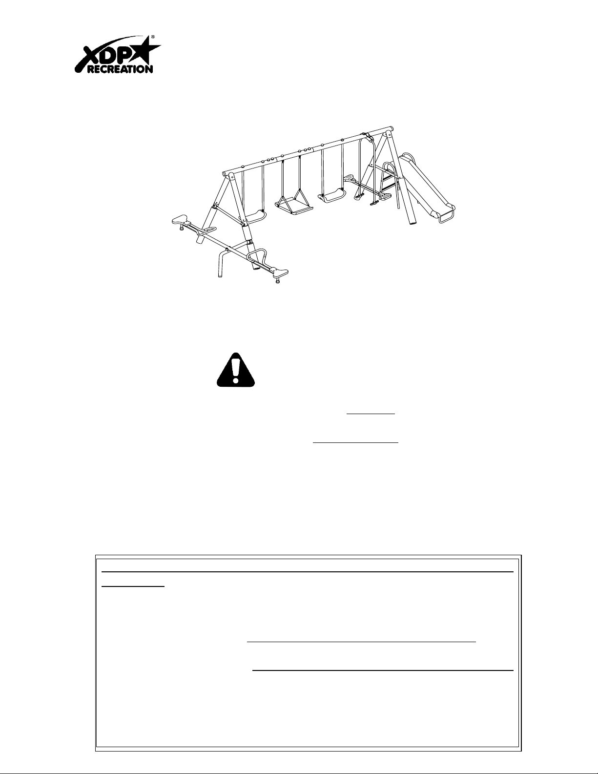
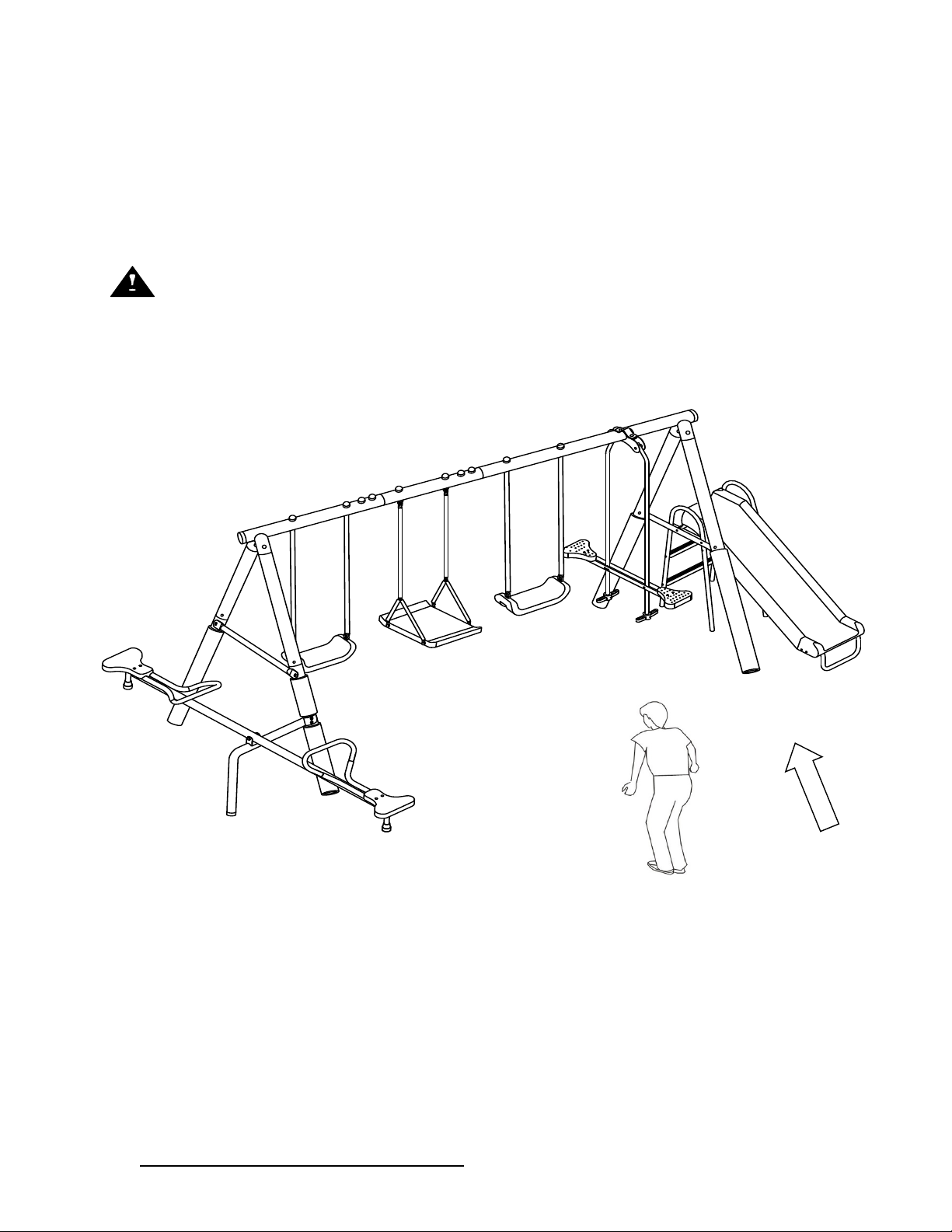
“CRESTVIEW” 4 Leg Swing Set w. SeeSaw
Model # 94570
Assembled dimensions are 165" x 106" x 74". Allow 6 - 12 ft of clearance around the perimeter of the swing set area when fully
assembled.
OWNER'S MANUAL, ASSEMBLY INSTRUCTIONS, CARE, MAINTENANCE AND USER'S
GUIDE
WA RN I NG !
Please read this entire instruction and assembly manual completely before proceeding. Yo u m us t f o ll o w a l l s a fe t y i ns t ru c t io n s
while using this equipment. The surface area where this swing set is set up must be level and free of all debris. This set is designed
to be anchored into the ground and is not to be set up on any hard surfaces such as concrete, hardened soil, or asphalt. Proper
surfacing under and surrounding the set adds to the safety level such as sand or mulch. Read all cautionary statements on the
following pages before using this equipment and save this instruction manual. DO NOT ALLOW CHILDREN TO PLAY ON
THIS GYM SET UNSUPERVISED! CONSTANT ADULT SUPERVISION IS REQUIRED. Do not use when raining or
during any inclement weather (i.e. rain, sleet, snow, ice, high winds, thunderstorms, or lightening). DO NOT ALLOW
CHILDREN TO JUMP ON OR CLIMB UP ON THIS SET'S TOP BAR.
For warranty details and registration card see the back page of this manual.
FOLLOW ALL ASSEMBLY INSTRUCTIONS AS WRITTEN IN THIS MANUAL
Please retain sales receipt for warranty purposes. DO NOT RETURN THE SET TO
THE STORE. If replacement parts or customer service is needed please contact XDP Recreation by email at service@xdp-
recreation.com or by calling 1-866-884-0535 between 8:00am and 5:00pm (Eastern Standard Time), Monday - Friday. This gym is designed
to be used safely by up to eight (8) children, ages 3 years to 8 years, with weight capacity of 100 lbs per child or total combined weight limit
of 800 lbs for all eight (8) children. This play gym is designed for backyard use only and is NOT intended for playgrounds, schools, day
care facilities, nurseries or other public places. Follow all assembly instructions carefully and as directed in this manual. This gym
conforms to all safety requirements by ASTM for Home Playground equipment when properly assembled using the instructions enclosed.
Adult assembly is required. Contains small parts. For proper stability and safety this gym set should be installed with ground anchors.
It is highly recommended that you seek the opinion from a local licensed contractor on the best way to secure the swing set in your
location.
IF NEEDED, GROUND ANCHORS CAN BE BOUGHT FROM THE STORE YOU PURCHASED THIS SET AT OR BY
PURCHASING FROM XDP RECREATION'S WEBSITE AT www.xdp-recreation.com
Page 2

IMPORTANT INSTRUCTIONS AND WARNINGS
WARNING
READ ALL INSTRUCTIONS BEFORE ASSEMBLING OR USING THIS EQUIPMENT
AGE LIMIT
l This product is designed to be used by up to eight (8) children between the ages of 3 to 8. Maximum user
weight is 100 pounds (45 kg) each with a combined maximum weight of 800 pounds (363 kgs).
l The play set is designed for children over three (3) years of age up to (8) years of age. Use by smaller
children can result in entrapment or serious injury.
l On-site adult supervision is required at all times for children of all ages.
l Do not allow use by children with any physical condition that may affect his/her ability to use this equipment
safely.
BEFORE YOU BEGIN
l Carefully read all instructions in this manual before assembling and using this product.
l The unit must be assembled by adults. Heavy duty working gloves must be worn to avoid injuries during
assembly.
l Children must not use the equipment until it is properly assembled and anchored.
l Adult supervision is required during the use of this equipment at all times.
l Unpack all parts. Take a complete inventory of all parts and hardware using the parts and hardware lists in
the following pages. If any parts are missing, do not return to the store. Please call customer service toll-free
number listed on the cover page for assistance. Store the product back in the original box and do not begin
to install until all parts are obtained.
LOCATION OF PLAY SET
l The equipment must be placed more than six (6) feet (1.8 meters) from any structures or obstructions,
including but not limited to buildings, fence, garage, trees, laundry lines, electrical wires. Children can be
seriously injured running or swinging into obstacles.
l The play set must be installed on level ground. Uneven ground must be leveled prior to installation.
Installation on sloping or uneven ground will put stress on the joints, causing the unit to become loose and
unstable which may result in serious injuries.
l Remove any tripping hazards from the safe play area, such as roots, tree stumps, rocks, landscaping,
sprinkler heads, railroad ties, plumbing and electrical connections.
l It is highly recommended that you seek the opinion from a local licensed contractor on the best way to secure
the swing set in your location.
l Windy conditions: it is possible for the product to be blown about by a high wind. if you anticipate
high winds, the frame should be secured to the ground with the use of an Anchor kit. If you anticipate
severe winds, the product should be moved to a sheltered location or completely disassembled.
Anchor kits can be ordered directly from XDP RECREATION at https//:www.xdp-recreation.com or by
calling 1-866-884-0535.
1
Page 3

DO NOT RETURN TO RETAILER WHERE PURCHASED.
CONTACT XDP FOR PARTS AND SUPPORT AT 1.866.8 84 .0535 o r servic e@ xdp-recreation.com
2
Do not install your play set over hard surface, e.g. asphalt, concrete, packed earth, tile or brick floor.
A fall onto a hard surface can result in serious injury or death to the user. The following is a list of
recommended ground covers from the Consumer Product Safety Commission:
SUGGESTED MATERIAL UNCOMPRESSED DEPTH
Double Shredded Bark Mulch 9”
Uniform Wood Chips 12”
Fine Gravel 12”
Fine Sand 12”
The Consumer Product Safety Commission’s Outdoor Home Playground Safety Handbook recommends to
install and maintain the playground equipment over at least 9 inches of wood chips, mulch or shredded
rubber (for equipment up to 8 feet high) or sand or pea gravel (for equipment no more than 5 feet high) as
shock absorbing material. Dirt and grass, which are the most prevalent surfaces under home playground
equipment, do not adequately protect children from serious head injuries. Install protective surfacing at
least six feet in all directions from play equipment. For swings, the surface should extend, in back and front,
twice the height of the suspending bar. Yo u shoul d co ns ul t a lo ca l contrac to r ab ou t w ay s to se cu re th e
product in your location. Do not install your play set over hard surface, e.g. asphalt, concrete, packed earth,
tile or brick floor. Please refer to the CONSUMER PRODUCT SAFETY COMMISSION’S OUTDOOR
HOME PLAYGROUND SAFETY HANDBOOK for detailed guidelines to prevent injuries from falls and other
hazards on public and home playgrounds.
SELECT PROTECTIVE SURFACING:
One of the most important things you can do to reduce the likelihood of serious head injury’s is to install shock-
absorbing protective surfacing under and around your play equipment. The Protective surfacing should be applied
to a depth that is suitable for the equipment height in accordance with ASTM F1292.
NOTE: DO NOT install home playground equipment over concrete, asphalt, or any other hard surface. A Fall
onto a hard surface can result in serious injury to the equipment user. Grass and dirt are not considered protective
surfacing because wear and environmental factors can reduce their shock absorbing effectiveness. Carpeting and
thin mats are generally not adequate protective surfacing. Ground Level equipment – such as Sand-Box, activity
wall, playhouse or other equipment that has no elevated play surface – does not need any protective surfacing.
WARNINGS ON ANCHORING
It is highly recommended the product be anchored into the ground to prevent movement and to make the swing
set more stable during use.
Some consumers want an anchoring system that allows the product to be moved to different locations. Other
consumers want to keep their swing set in a permanent location.
It is highly recommended that you seek the opinion from a local licensed contractor on the best way to secure
the swing set in your location. The best way to anchor a product is to create a concrete footing and use that as a
base for an anchor. Whatever method you prefer for your location, an anchoring system for this product should
be used at all times.
WEATHER CONDITIONS
l DO NOT use this equipment if the swing seat, slide, stand n swing, see-saw or any parts are wet. Use the
play set only when the parts are clean and dry. If the equipment is wet, the user could slip and suffer injuries.
l Please be aware of weather conditions when using the equipment. If it is too windy, users could lose control
and suffer injuries. The playground equipment must be properly anchored, stored away or restricted from use
during inclement weather such as heavy winds or severe weather storms. You sh ou ld consult a local
contractor about ways to anchor the product in your location.
Page 4

DO NOT RETURN TO RETAILER WHERE PURCHASED.
CONTACT XDP FOR PARTS AND SUPPORT AT 1.866.8 84 .0535 o r servic e@ xdp-recreation.com
3
WARNING STATEMENTS – Observing the following statements and warnings reduces the likelihood of
serious or fatal injury.
l DO NOT allow more than one child to play on the individual swing or slide component at any one time.
l DO NOT allow children to stand on the slide, swing seats, see-saw or glide ride. The glide ride is made for
only two users at a time. The Stand N Swing is made for one user at a time!
l DO NOT allow children to walk too close to moving parts. ALWAYS keep a safe distance to avoid being
struck by other children while playing on swings, slides, stand n swing, and glide ride etc.
l DO NOT allow children to twist the swing chains or loop them over the top support bar as this may reduce
the strength of the chain.
l DO NOT swing empty seats as this may cause injuries.
l Children should not walk close to, in front of, behind, or between moving items.
l DO NOT CLIMB on the Equipment when the Equipment is wet.
l DO NOT attached items to the equipment that are not specifically designed for use with the equipment, such
as, but not limited to, Jump Ropes, Clothesline, pet leashes, cables, and chain as they may cause a
strangulation hazard.
l Dress Children with well-fitting and full foot enclosing footwear. Examples of in-appropriate footwear are:
CLOGS, flip flops, and sandals.
l ALWAYS guide children to sit in the center of swinging parts, with their full weight placed in the seat center
and holding on to the swing chains.
l DO NOT allow children to jump off the equipment while it is in motion. ALWAYS come to a full stop before
dismounting.
l ALWAYS dress children appropriately for proper play, e.g. wear well-fitted rubber sole shoes, and remove
loose or sharp items such as jewelry, hair accessories, scarves which may become entangled in the
equipment or cause injuries.
l ALWAYS make sure children remove their bike or other sports helmets before playing on the playground.
l DO NOT allow children to slide down the slide head first.
l DO NOT allow children to climb onto swing or jump to/from different play areas of the equipment.
l ALWAYS return safely to the ground before approaching another play area.
l DO NOT allow children to climb on structural parts (e.g. legs, top bar). These are structural components
and are not designed for play.
l ALWAYS check the slide or other parts exposed to the body for extreme heat from the sun before allowing
children to use the equipment.
l ALWAYS prevent access and secure from any unauthorized use when there is no adult supervision.
l DO NOT allow pets or other animals near the equipment to prevent damage or injuries.
l Adequate overhead clearance is essential. A minimum of 24 ft (7.3 meters) from ground level is
recommended. Provide clearance for wires, tree limbs, and other possible hazards.
l Use the swing set in a well-lit area. Artificial illumination may be required for shady areas.
Page 5

DO NOT RETURN TO RETAILER WHERE PURCHASED.
CONTACT XDP FOR PARTS AND SUPPORT AT 1.866.8 84 .0535 o r servic e@ xdp-recreation.com
4
INSPECTION PRIOR TO EACH USE OR DAILY INSPECTION
l DO NOT use the equipment if any bolts or nuts are missing or loose. ALWAYS check to ensure the
equipment and all parts are well secured and stable before each use.
l ALWAYS clear the play area of any rocks, sharp objects, or any materials that could be potentially hazardous
to users.
l DO NOT attach items to the equipment that are not specifically designed for use with the equipment, including,
but not limited to, jump ropes, clothesline, pet leashes, cables and chains as they may cause choke hazards.
l The steel and plastic parts used in your product are subject to normal wear. Gradual deterioration of the
material will occur, the speed of which will depend on the level of exposure to UV rays, airborne pollution,
outdoor weather conditions such as rain and wind and the amount of use. You must inspect the equipment
prior to every use. This includes, but is not limited to inspecting the set for cracks, excess wear, missing
parts, loose connections, and for overall integrity. When the set shows any signs of weakness, you must
stop using the play set immediately, properly store the set or restrict access by users until the condition is
resolved.
l Verify that the chains are secured at both ends and tightened, so that there is no loose chain hanging
that can result in choking hazard.
When conducting inspections, it is recommended that you use the Suggested General Maintenance
Checklist and Routine Inspection and Maintenance Issues checklists provided by the US Consumer Product
Safety Commission, a copy of which is contained in this user manual.
CARE & MAINTENANCE INSTRUCTIONS
l Inspect all nuts and bolts twice monthly during the usage season for tightness and tighten as required. It is
particularly important that this procedure is followed at the beginning of each season.
l Oil all metallic moving parts monthly during the usage period.
l Sand rusted areas on metal tubing and repaint using a nonlead-based paint meeting the requirements of
Title 16 CFR Part 1303.
l Check swing seats, stand n swing, and chains monthly during usage season for deterioration.
Replacements should be made in accordance with the manufacturer’s instructions.
l Check all coverings for bolts and sharp edges twice monthly during usage season to be certain that they
are in place and replace when necessary. It is especially important to do this at the beginning of each new
season.
l Do not use when the temperature drops below 32 degrees F (0 degrees C); remove and store the plastic
swing seats, stand n swing, and slide indoors.
Page 6
DO NOT RETURN TO RETAILER WHERE PURCHASED.
CONTACT XDP FOR PARTS AND SUPPORT AT 1.866.8 84 .0535 o r servic e@ xdp-recreation.com
5
ANCHORING
(NOTE:ANCHORS ARE NOT INCLUDED-MUST BE PURCHASED SEPARATELY)
There are different ways of anchoring the equipment, depending on the type of ground on which the
equipment is to be installed. Make sure that all anchors are below ground level to prevent tripping.
You should consult your local contractor to decide the most appropriate way to anchor the
equipment in your location.
The following anchoring options may be considered:
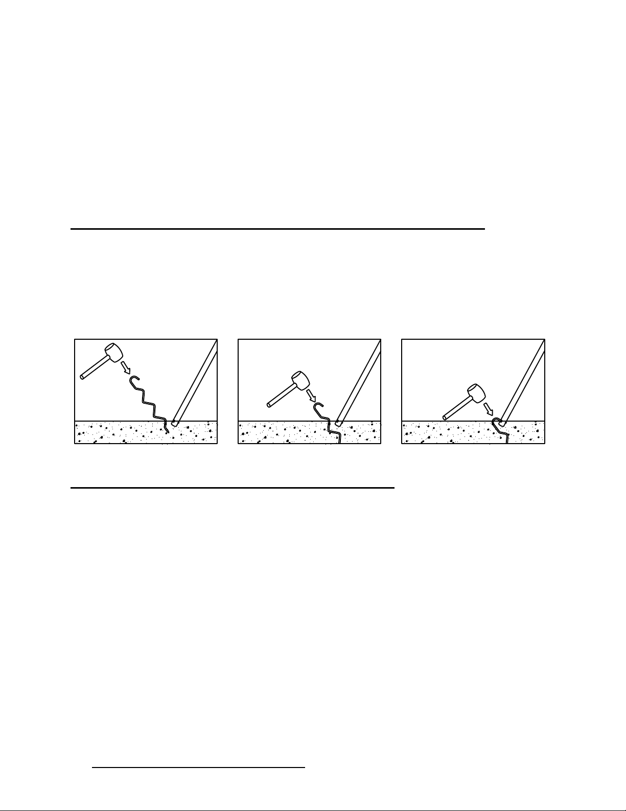
Corkscrew Anchoring (Corkscrew Anchors not included)
l If your soil is hard (clay, etc.), the corkscrew method may be suitable.
l Be sure that the swing set is located on level ground.
l Twist the corkscrew anchor into the ground until only the end with the hook is above the ground
and next to the leg. Insert the hook into the bottom opening of the leg.
Ensure that the hook is secured onto the leg opening.
Concrete Anchoring (Materials not included)
● If the swing set is set up on grounds with sandy soil (soft) condition, it must be anchored
with concrete footing (concrete not included)
● Be sure that the swing set is assembled and placed on level ground
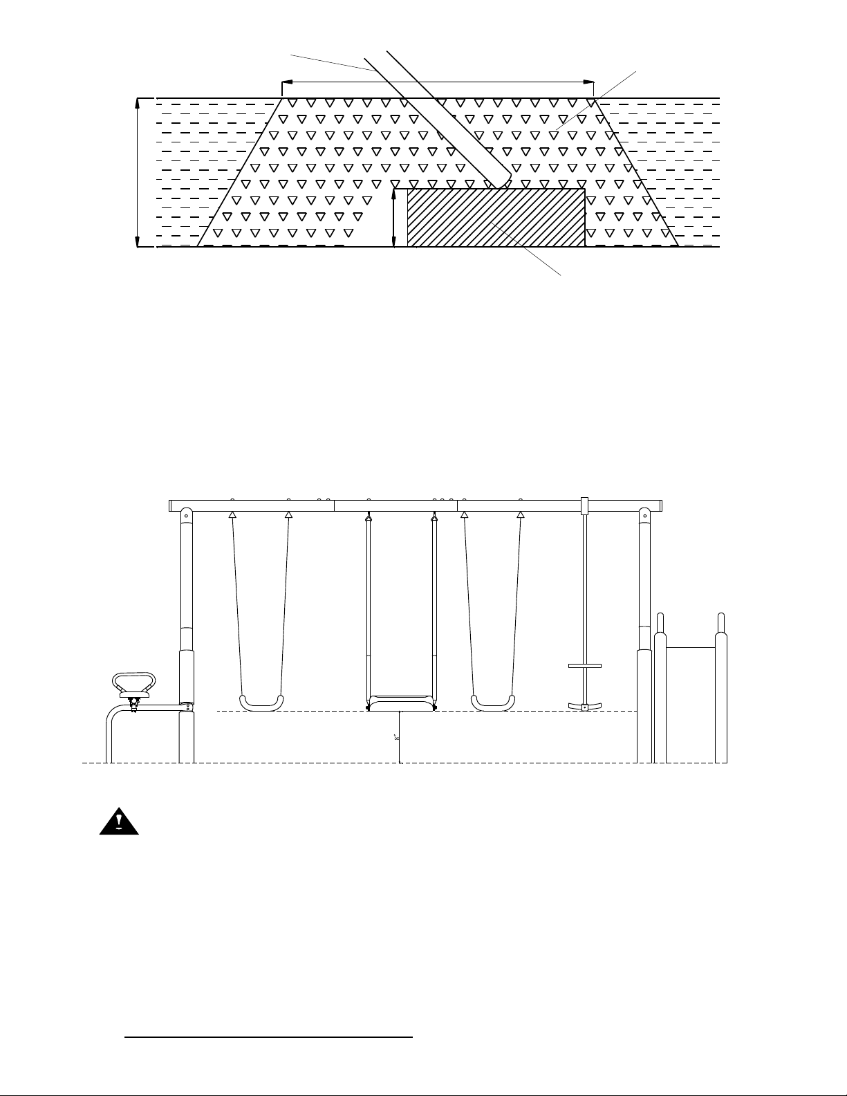
● Dig holes around swing leg tube, as shown in drawing in the next page. As you dig deeper,
enlarge the diameter of the hole to fix the cement
● Place 2 inches of brick or gravel underneath the leg, as shown in drawing in the next page
● Use about 45 lbs. of concrete per leg
● Cover the concrete with dirt and protective surface material
● Allow 6-7 days for the concrete to dry properly
Page 7
DO NOT RETURN TO RETAILER WHERE PURCHASED.
CONTACT XDP FOR PARTS AND SUPPORT AT 1.866.8 84 .0535 o r servic e@ xdp-recreation.com
6
Note: The maximum fall height for this product is 4 feet. The minimum ground
clearance between the bottom of the suspended plays and the playing or
ground surface must be 8 inches.
You mus t maintain a minimum of 8 i nches of ground clearance.
WARNING
Please properly anchor the swing set to minimize the risk of injury or death.
If the swing set is used without proper anchoring, it may be dangerous and may
tilt over.
8”
FRAME LEG
CONCRETE
BRICK OR GRAVEL BED
2”
12-5/8”
5”
Page 8

DO NOT RETURN TO RETAILER WHERE PURCHASED.
CONTACT XDP FOR PARTS AND SUPPORT AT 1.866.8 84 .0535 o r servic e@ xdp-recreation.com
7
CARE AND MAINTENANCE CHECKLIST
AT THE BEGINNING OF EACH PLAY SE ASON:
n Tighten all hardware.
n Lubricate all metallic moving parts per manufacturer’s instructions.
n Check all protective coverings on bolts, pipes, edges, and corners. Replace if they are loose,
cracked, or missing.
n Check all moving parts including swing seats and chains for wear, rust or other deterioration.
Replace as needed.
n Check metal parts for rust. If found, sand and repaint using a non-lead paint meeting the
requirements of 16 CFR 1303.
n Reinstall any plastic parts, such as swing seats or any other items that were removed for the cold
season.
n Rake and check depth of loose fill protective surfacing materials to prevent compaction and to
maintain appropriate depth. Replace as needed.
TWICE A MONTH DURING PLAY SEASON:
n Tighten all hardware.
n Check all protective coverings on bolts, pipes, edges and corners. Replace if they are loose,
cracked or missing.
n Rake and check depth of loose fill protective surfacing materials to prevent compaction and to
maintain appropriate depth. Replace as needed.
ONCE A MONTH DURING PLAY SEASON:
n Lubricate all metallic moving parts per manufacturer’s instructions.
n Check all moving parts including swing seats and chains for wear, rust or other deterioration.
Replace as needed.
n Rake and check depth of loose fill protective surfacing materials to prevent compaction and to
maintain appropriate depth. Replace as needed.
AT THE END OF EACH PLAY SEASON:
n At the end of each play season or when the temperature drops below 32 degrees F (0 degrees C).
n Remove plastic swing seats and other items as specified by the manufacturer and take indoors or
do not use.
n Rake and check depth of loose fill protective surfacing materials to prevent compaction and to
maintain appropriate depth. Replace as needed.
As a general rule, maintenance should be performed at any time it is deemed necessary.
DISPOSAL INSTRUCTIONS
u Please use care when disassembling the equipment, when it is no longer in operational condition.
Wear heavy duty working gloves to avoid injuries.
u Fully disassemble the entire swing and slide sets before disposal. Do not leave partially
disassembled parts in areas accessible by children.
u Should you wish to recycle the steel tubing, please take the frame to your local recycling center.
u All plastic parts can be recycled, take it to your local recycling center. Do not let children play with
any disassembled parts meant for disposal, such as chains, slide, tubing, bolts, nuts, screws, etc.
u All rusted parts, bolts must be properly disposed of in trash bin. Do not reuse.
Owners shall be responsible for maintaining the legibility of the warning labels.
Page 9
DO NOT RETURN TO RETAILER WHERE PURCHASED.
CONTACT XDP FOR PARTS AND SUPPORT AT 1.866.8 84 .0535 o r servic e@ xdp-recreation.com
8
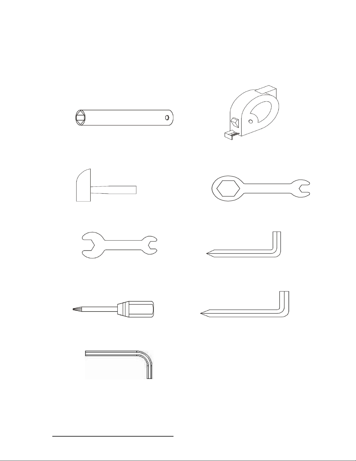
TOOLS NEEDED
Please prepare the following tools
prior to assembling this equipment.
Special Socket Wrench Tape Measure
(Included) (Not included)
Hammer Wrench
(If you intend to install anchor, this is needed) (Included)
Wrench Big Allen Wrench
(Not Included) (Included)
Flat Head and Philips Head Screwdriver Medium Allen Wrench
(Not included) (Included)
8
Small Allen Wrench
Not Included)
Page 10
DO NOT RETURN TO RETAILER WHERE PURCHASED.
CONTACT XDP FOR PARTS AND SUPPORT AT 1.866.8 84 .0535 o r servic e@ xdp-recreation.com
9
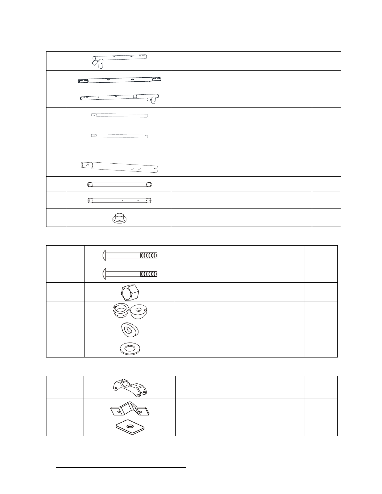
Part list for main frame assembly
A1
LEFT TOP BAR
1
A2
MIDDLE TOP BAR
1
A3
RIGHT TOP BAR
1
A4
TOP SECTION LEG
4
A5
BOTTOM SECTION LEG WITH FOAM
(WITH TWO HOLES)
3
A6
BOTTOM SECTION LEG WITH
FOAM(WITH FOUR
HOLES)
1
A7 CROSS BAR (WITH TWO HOLES)
1
A8 CROSS BAR (WITH FOUR HOLES)
1
C2 END CAP (PRE-ASSEMBLED)
2
Hardware used for main frame assembly
B1 BOLT 5/16"x2-1/2"
12
B2 BOLT 5/16"x2-5/8"
4
B3 NYLON NUT 5/16’’
16
B4
PLASTIC CAP (WITH ARC WASHER)
16
B5 ARC WASHER 5/16’’
12
B6
WASHER 5/16’’
4
Bracket used for glide ride assembly
L3
BRACKET
1
L4 BRACKET CLAMP
1
L5
REINFORCING STEEL SPACER
2
Page 11
DO NOT RETURN TO RETAILER WHERE PURCHASED.
CONTACT XDP FOR PARTS AND SUPPORT AT 1.866.8 84 .0535 o r servic e@ xdp-recreation.com
10
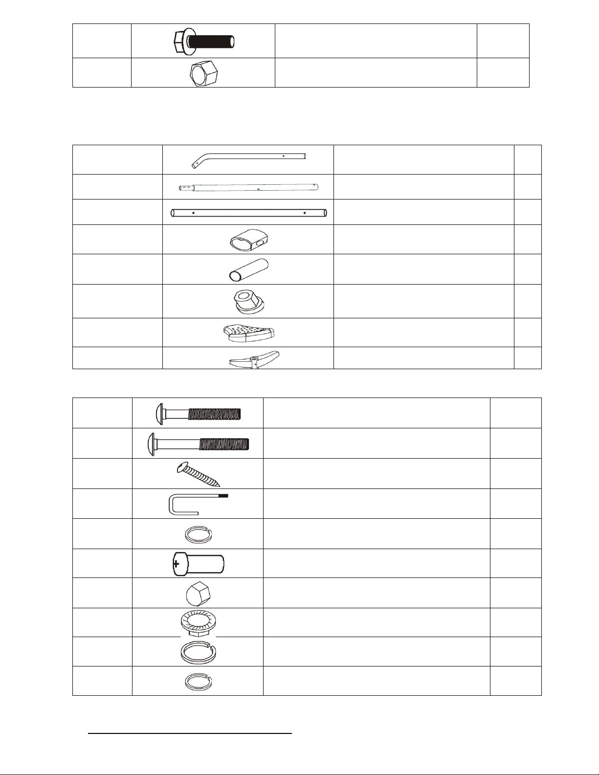
N3R BOLT 5/16”x1”
2
N7 NYLON NUT 5/16’’
2
Part list for glide ride assembly
L1-N
TOP SECTION HANGER
2
L2-N
BOTTOM SECTION HANGER
2
L3-N
GLIDE SEAT SUPPORT
2
M1
TUBE CAP(PRE-ASSEMBLED)
2
M2
SMALL NYLON BEARING (PRE-
ASSEMBLED)
2
M3
LARGE NYLON BEARING (PRE-
ASSEMBLED)
4
M4 GLIDE SEAT
2
M5 FOOTREST
2
Hardware used for glide ride assembly
N1
BOLT 1/4”x1-1/2”
4
N2R
BOLT 1/4’’x1-7/10”
2
N4
SCREW 0.22”x3/4”
4
N5
J-BOLT
2
N6 SPRING WASHER (SMALL)
8
N8
CAP BOLT 1/4”x1/2”
2
N9
CAP NUT 1/4”
8
N10
NUT 1/4”
2
N11 SPRING WASHER (LARGE)
2
N12 SPRING WASHER (MEDIUM)
4
Page 12

DO NOT RETURN TO RETAILER WHERE PURCHASED.
CONTACT XDP FOR PARTS AND SUPPORT AT 1.866.8 84 .0535 o r servic e@ xdp-recreation.com
11
N13
BOLT 1/4”x1-3/8"
4
N14 ARC WASHER 5/16"
8
Page 13
DO NOT RETURN TO RETAILER WHERE PURCHASED.
CONTACT XDP FOR PARTS AND SUPPORT AT 1.866.8 84 .0535 o r servic e@ xdp-recreation.com
12
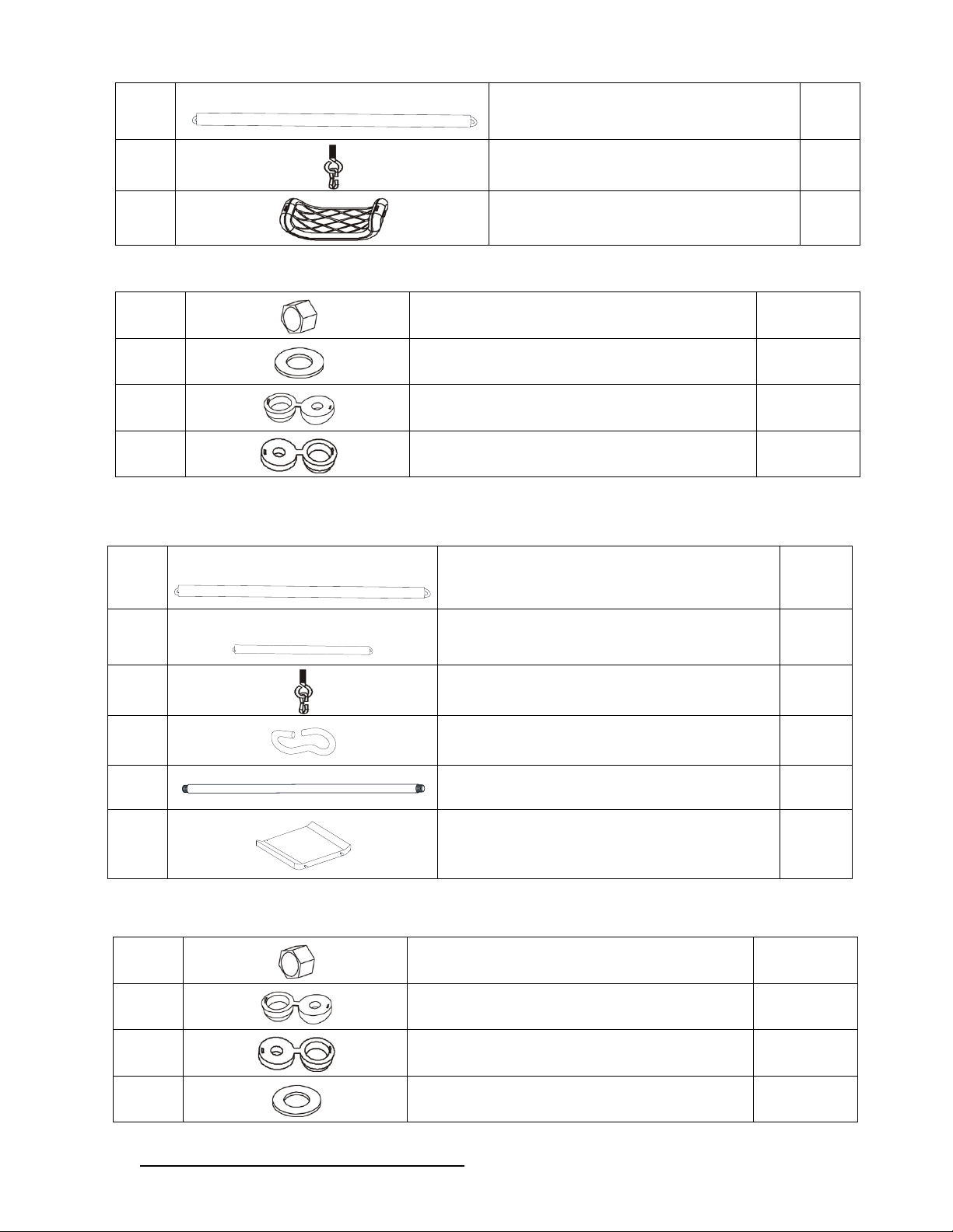
Part list for swing seat assembly
J1
PVC COVERED CHAIN (PRE-
ASSEMBLED)
4
J3
EYE BOLT WITH ATTACHMENT
BOLT(PRE-ASSEMBLED)
8
K1
SWING SEAT
2
Hardware used for swing seat assembly
Part list for Standing N swing assembly
G1
PVC COVERED CHAIN (PRE-
ASSEMBLED)
2
G2
PVC COVERED CHAIN (PRE-
ASSEMBLED)
4
G3
EYE BOLT WITH ATTACHMENT
BOLT(PRE-ASSEMBLED)
2
G4 EYE BOLT (PRE-ASSEMBLED)
6
G5
FOOTREST SUPPORT
2
G6
Standing N swing
1
Hardware used for Standing N swing assembly
J6
NYLON NUT 5/16’’
8
J7
WASHER 5/16’’
4
J8 PLASTIC CAP (WITH ARC WASHER)
4
J9 PLASTIC CAP (WITH FLAT WASHER)
4
G7
NYLON NUT 5/16’’
6
G8 PLASTIC CAP (WITH ARC WASHER)
2
G9
PLASTIC CAP (WITH FLAT WASHER)
4
G10
WASHER 5/16’’
4
Page 14
DO NOT RETURN TO RETAILER WHERE PURCHASED.
CONTACT XDP FOR PARTS AND SUPPORT AT 1.866.8 84 .0535 o r servic e@ xdp-recreation.com
13
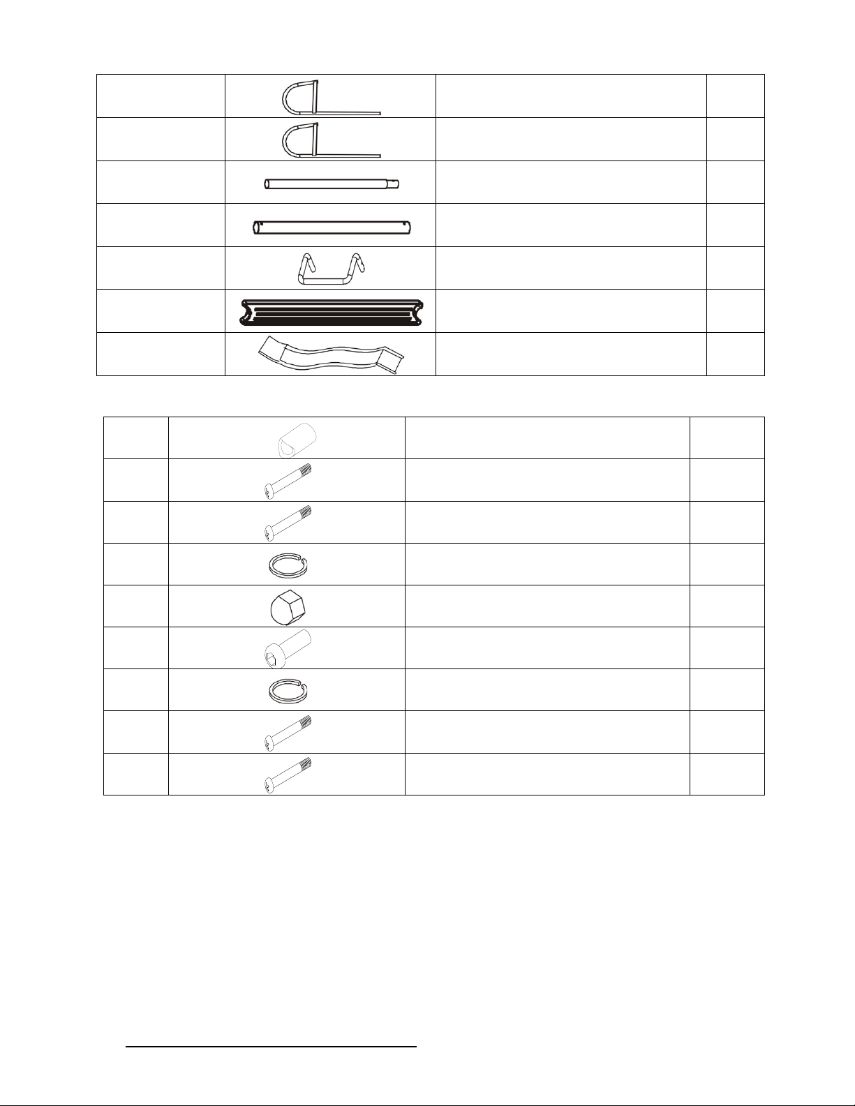
Part list for slide assembly
X1-N
SLIDE SUPPORT (WITH
OPENING)
1
X2-N SLIDE SUPPORT
1
X3-N SLIDE LEG TUBE
2
X4-N
SLIDE TOP SUPPORT BAR
1
X5-N
SLIDE FRONT SUPPORT
1
X6 SLIDE LADDER STEPS
2
Y2
SLIDE
1
Hardware used for slide assembly
Y1 PLASTIC CONNECTOR
2
Z1
BOLT 1/4"x1-1/2"
6
Z2
BOLT 1/4"x5"
2
Z3 SPRING WASHER (LARGE)
4
Z4
CAP NUT 1/4”
10
Z5 CAP BOLT 1/4"x1/2"
4
Z6 SPRING WASHER (SMALL)
20
Z7
BOLT 1/4"x3"
2
Z8
BOLT 1/4"x2- 1/4"
4
Page 15
DO NOT RETURN TO RETAILER WHERE PURCHASED.
CONTACT XDP FOR PARTS AND SUPPORT AT 1.866.8 84 .0535 o r servic e@ xdp-recreation.com
14
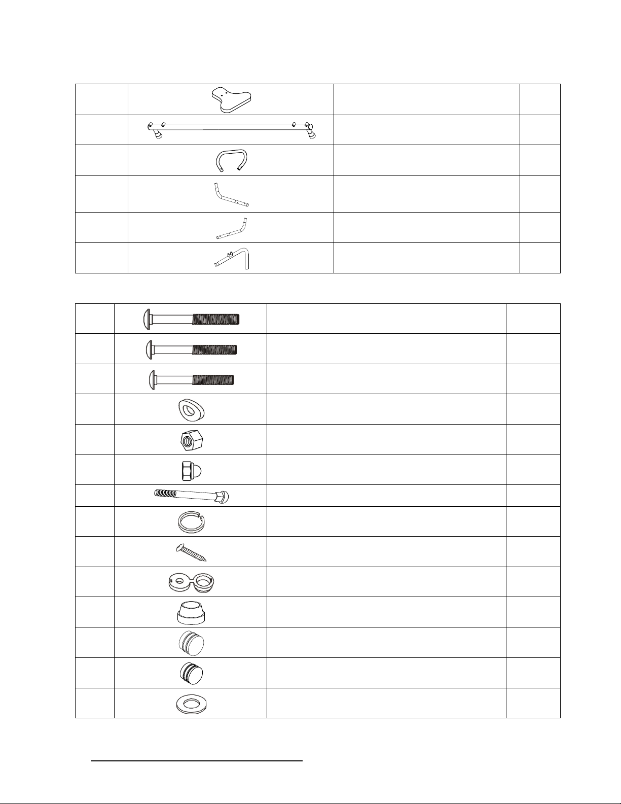
Part list for see-saw assembly
U16
SEAT
2
U17 SEAT SUPPORT
1
U18 HANDLE BAR
2
U19-1
LEFT HANDLE BAR SUPPORT
2
U19-2
RIGHT HANDLE BAR SUPPORT
2
U20 L SHAPED TUBE
1
Hardware used for seesaw assembly
U1
BOLT 5/16”x3-1/4”
4
U2
BOLT 5/16”x2-1/2”
1
U3
BOLT M8x2-10/16”
2
U4 ARC WASHER Φ8.5XT1/8”
10
U5
NYLON NUT 5/16”
7
U6
CAP NUT 1/4”
4
U7
BOLT 1/4”x1-1/2”
4
U8
SPRING WASHER
4
U9
SCREW M4x1/2”
4
U10 PLASTIC CAP (WITH FLAT WASHER)
1
U11 SHOCK PAD (PRE-ASSEMBLED)
2
U12
END COVER FOR SEAT SUPPORT (PRE-
ASSEMBLED)
3
U13
END COVER FOR HANDLE BAR
SUPPORT (PRE-ASSEMBLED)
4
U14
WASHER
1
Page 16

DO NOT RETURN TO RETAILER WHERE PURCHASED.
CONTACT XDP FOR PARTS AND SUPPORT AT 1.866.8 84 .0535 o r servic e@ xdp-recreation.com
15
U15 PLASTIC CAP (WITH ARC WASHER)
2
U21 SPRING WASHER(SMALL)
4
Page 17

DO NOT RETURN TO RETAILER WHERE PURCHASED.
CONTACT XDP FOR PARTS AND SUPPORT AT 1.866.8 84 .0535 o r servic e@ xdp-recreation.com
16
ASSEMBLY INSTRUCTIONS
Ø Place the playground equipment on level ground and not less than
6ft (1.8m) from any structure or obstruction such as a fence, garage,
house, overhanging branches, laundry line, or electrical wires.
Ø Do not install the playground equipment over concrete, asphalt,
packed earth, or any other hard surface; a fall onto a hard surface can
result in serious injury or death to the equipment user.
Ø Adequate overhead clearance is essential. A minimum clearance from
ground level shall be recommended. Provide clearance for wires, tree
limbs, and other possible hazards.
Ø Use the swing set in a well-lighted area. Artificial illumination may be
required for shady areas.
Ø Secure the swing set against unauthorized and unsupervised use.
Ø The owner and supervisors of the swing set are responsible to make all
users aware of practices specified in the use instructions.
TIGHTENING NUTS & BOLTS
Ø For ease of installation, do not over-tighten the nuts and bolts when
you are first putting the equipment together. This will allow for some
possible adjustments during installation.
Ø Once you have finished assembling each component of the play set,
make sure to go back over each step and properly tighten all nuts,
bolts and plastic caps. Check the entire unit to ensure all parts are
properly assembled before allowing children to use the playground
equipment.
Page 18
DO NOT RETURN TO RETAILER WHERE PURCHASED.
CONTACT XDP FOR PARTS AND SUPPORT AT 1.866.8 84 .0535 o r servic e@ xdp-recreation.com
17
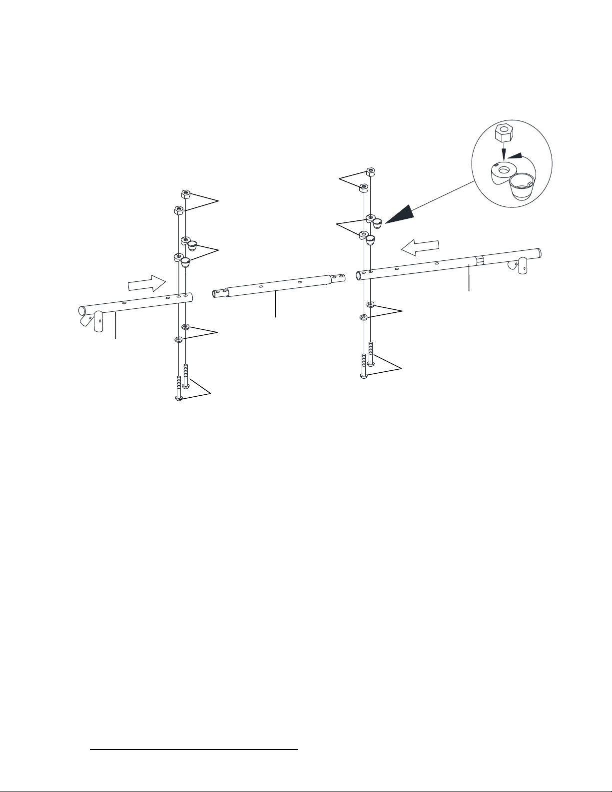
STEP 1 – Assemble the top bar frame of the swing set
Ø Connect A1A2and A3 and secure with B3, B4, B1 and B5 as shown below.
Note: All round holes should be facing up and concave holes facing down.
a
A2
A1
A3
B1
B1
B3
B3
B4
B4
B5
B5
Page 19
DO NOT RETURN TO RETAILER WHERE PURCHASED.
CONTACT XDP FOR PARTS AND SUPPORT AT 1.866.8 84 .0535 o r servic e@ xdp-recreation.com
18
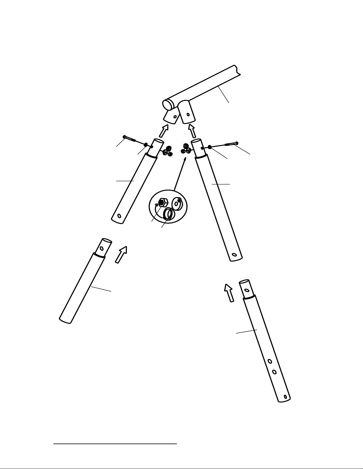
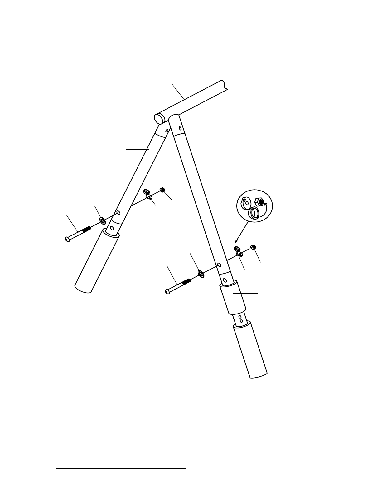
STEP 2 – Assemble the support legs of swing set
Ø Connect A1 to A4 and secure using B1, B5, B4 and B3 as shown below.
Ø Repeat the above step for the right side of the swing set (A3 and A4).
m
A4
A1
B1
B1
B3
B4
B5
B5
A4
A5
A6
Page 20

DO NOT RETURN TO RETAILER WHERE PURCHASED.
CONTACT XDP FOR PARTS AND SUPPORT AT 1.866.8 84 .0535 o r servic e@ xdp-recreation.com
19
Page 21
DO NOT RETURN TO RETAILER WHERE PURCHASED.
CONTACT XDP FOR PARTS AND SUPPORT AT 1.866.8 84 .0535 o r servic e@ xdp-recreation.com
20
g
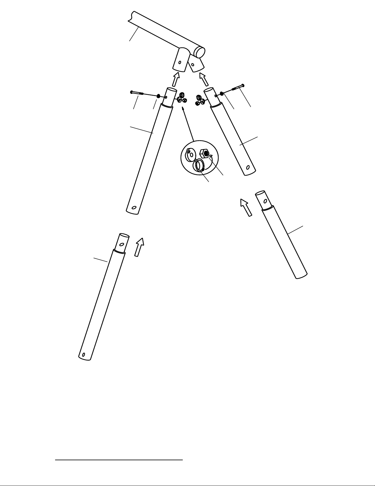
STEP 3 – Assemble the support legs of swing set
A4
A3
B1
B1
B3
B4
B5
B5
A4
A5
A5
Page 22
DO NOT RETURN TO RETAILER WHERE PURCHASED.
CONTACT XDP FOR PARTS AND SUPPORT AT 1.866.8 84 .0535 o r servic e@ xdp-recreation.com
21
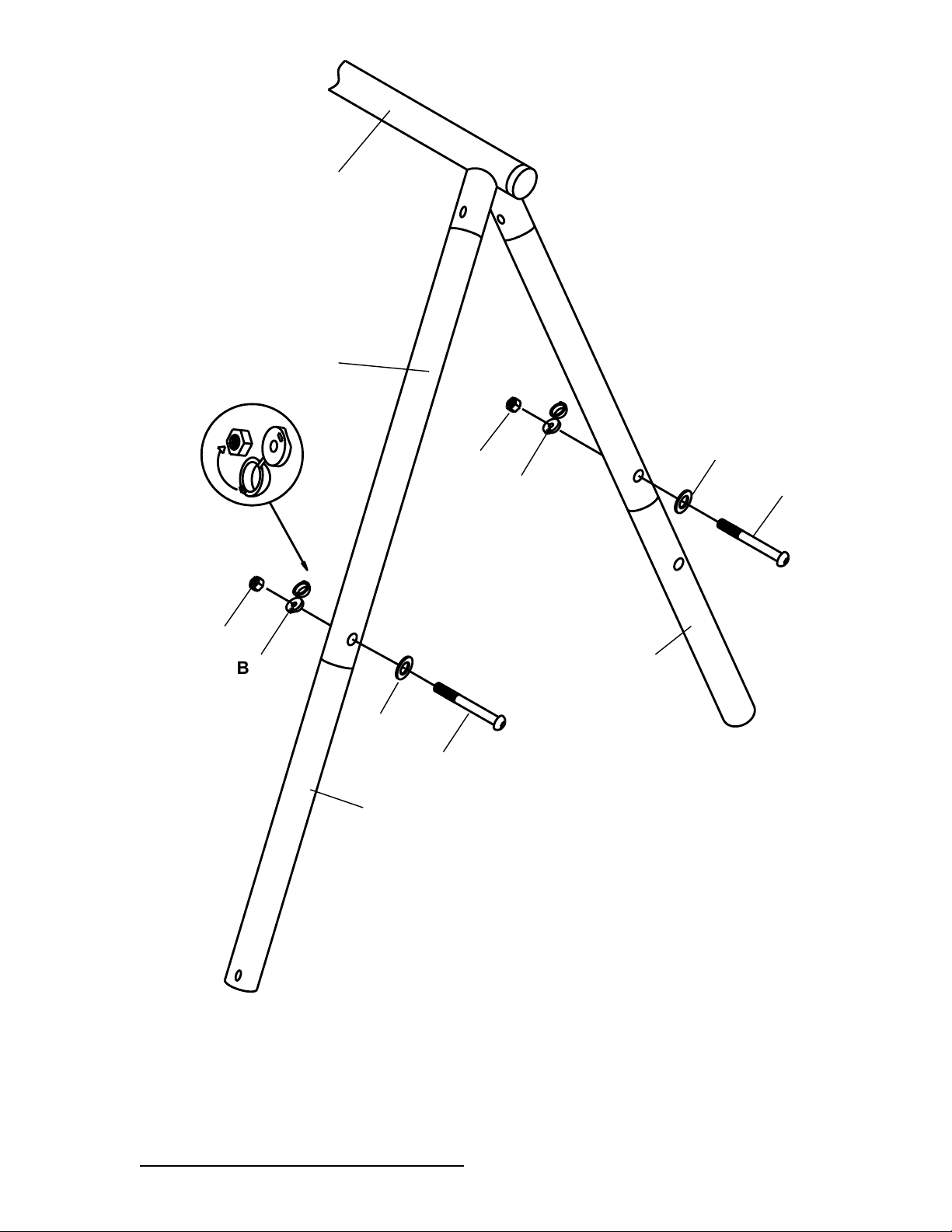
Ø Connect A4 to A5 and A6 and secure using B1, B5, B4 and B3 as shown below.
Repeat the above step for the right side of the swing set (A3 and A4, A5).
rly
B1
B1
B5
A4
B3
B4
B3
B4
B5
A5
A6
A1
Page 23
DO NOT RETURN TO RETAILER WHERE PURCHASED.
CONTACT XDP FOR PARTS AND SUPPORT AT 1.866.8 84 .0535 o r servic e@ xdp-recreation.com
22
o
STEP 3 – Attach the crossbar to the support legs
A4
A4
A5
A5
B1
B4
B4
B3
B3
A5
B5
B1
A3
Page 24
DO NOT RETURN TO RETAILER WHERE PURCHASED.
CONTACT XDP FOR PARTS AND SUPPORT AT 1.866.8 84 .0535 o r servic e@ xdp-recreation.com
23
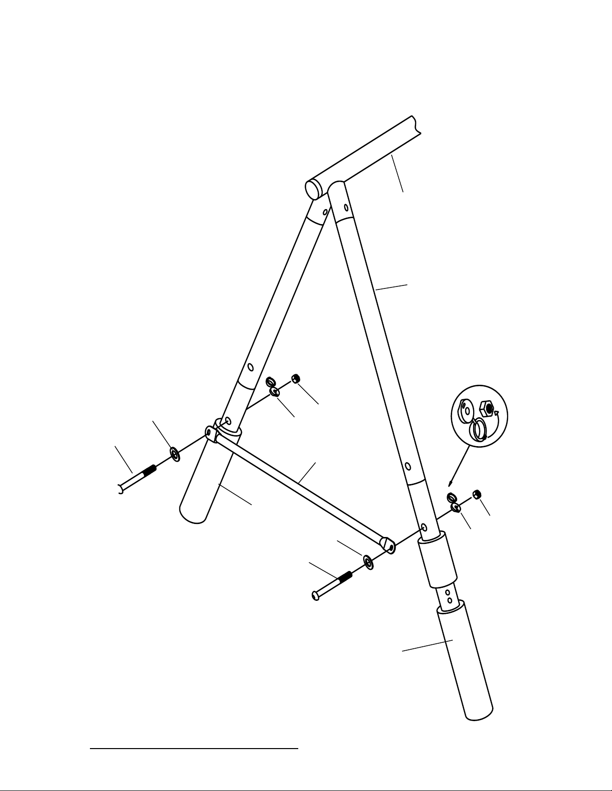
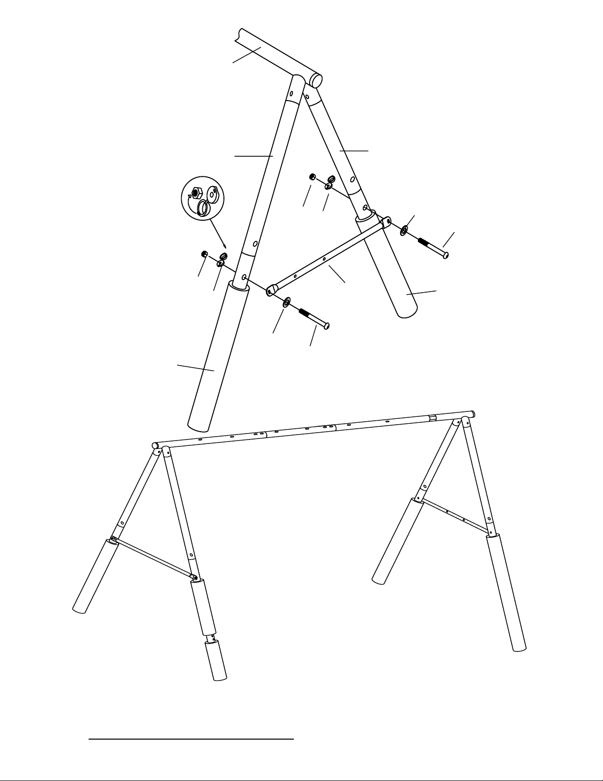
Ø Attach A7 to the outer side of A5, A6 and secure using B2, B6, B4 and B3.
23
Attach A8 to the outer side of A5 and secure using B2, B6, B4 and B3.
A7
A6
A4
B3
A5
B2
B6
B4
B2
A1
B6
B4
B3
Page 25
DO NOT RETURN TO RETAILER WHERE PURCHASED.
CONTACT XDP FOR PARTS AND SUPPORT AT 1.866.8 84 .0535 o r servic e@ xdp-recreation.com
24
a
24
A3
A4
A4
A8
B6
B2
B6
B2
B3
B3
B4
B4
A5
A5
Page 26
DO NOT RETURN TO RETAILER WHERE PURCHASED.
CONTACT XDP FOR PARTS AND SUPPORT AT 1.866.8 84 .0535 o r servic e@ xdp-recreation.com
25
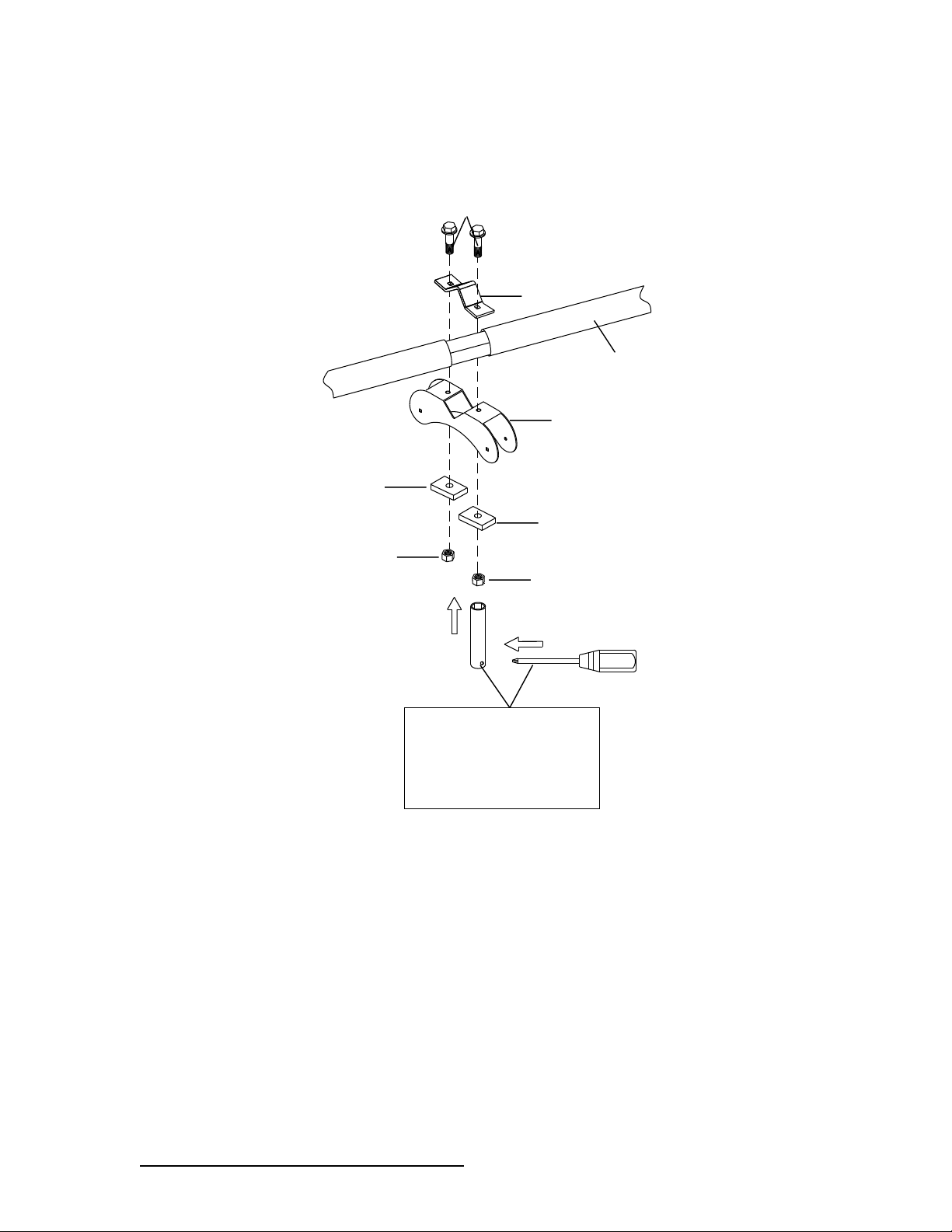
STEP 4 - Glide Ride assembly
Ø Attach L4 and L3 to A3 using N3R, L5 and N7 as shown. Use special socket wrench and
screw driver to tighten N3R and N7.
25
N3R
L5
L5
L3
A3
L4
N7
N7
USE SPECIAL SOCKET
WRENCH AND SCREW
DRIVER TO TIGHTEN
N7.
Page 27
DO NOT RETURN TO RETAILER WHERE PURCHASED.
CONTACT XDP FOR PARTS AND SUPPORT AT 1.866.8 84 .0535 o r servic e@ xdp-recreation.com
26
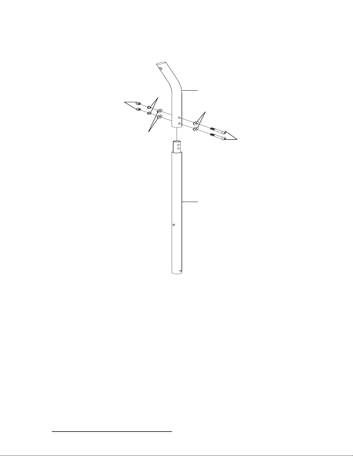
STEP 5 – Glide ride assembly (continued)
Ø Insert L1-N (straight end) into L2-N and secure with N14,N6 ,N9 and N13 on both sides.
Ø Repeat the above steps on the other side
L2-N
L1-N
N14
N9
N14
N13
N6
Page 28
DO NOT RETURN TO RETAILER WHERE PURCHASED.
CONTACT XDP FOR PARTS AND SUPPORT AT 1.866.8 84 .0535 o r servic e@ xdp-recreation.com
27
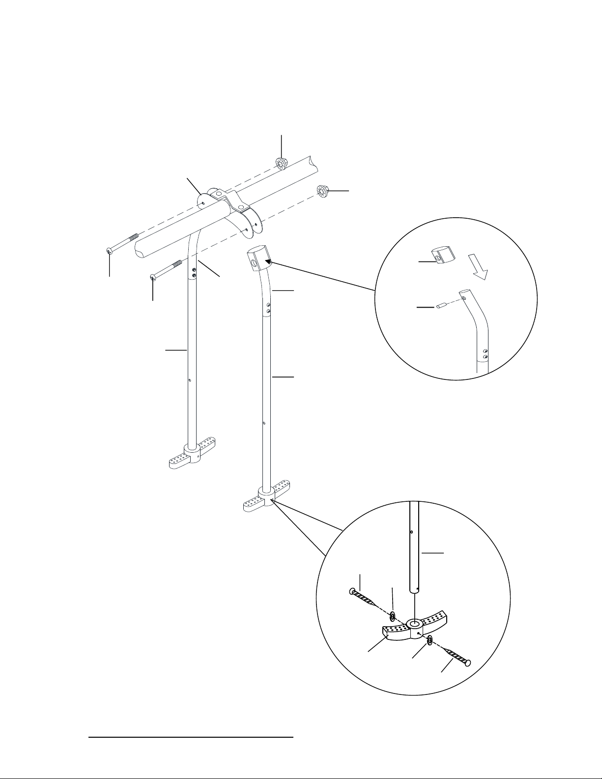
STEP 6 – Glide ride assembly (continued)
Ø Insert L2-N (straight end) into M5 and secure with N4 and N12 on both sides.
Ø Attach M1 to the top of L1-N (curved end). Align holes and insert M2.
Ø Attach L1-N to L3 on both sides and secure with N2R and N10.
3
L1-N
L2-N
L2-N
L1-N
N10
N10
L3
N2R
N2R
M1
M2
L2-N
N4
N12
N12
M5
Page 29
DO NOT RETURN TO RETAILER WHERE PURCHASED.
CONTACT XDP FOR PARTS AND SUPPORT AT 1.866.8 84 .0535 o r servic e@ xdp-recreation.com
28
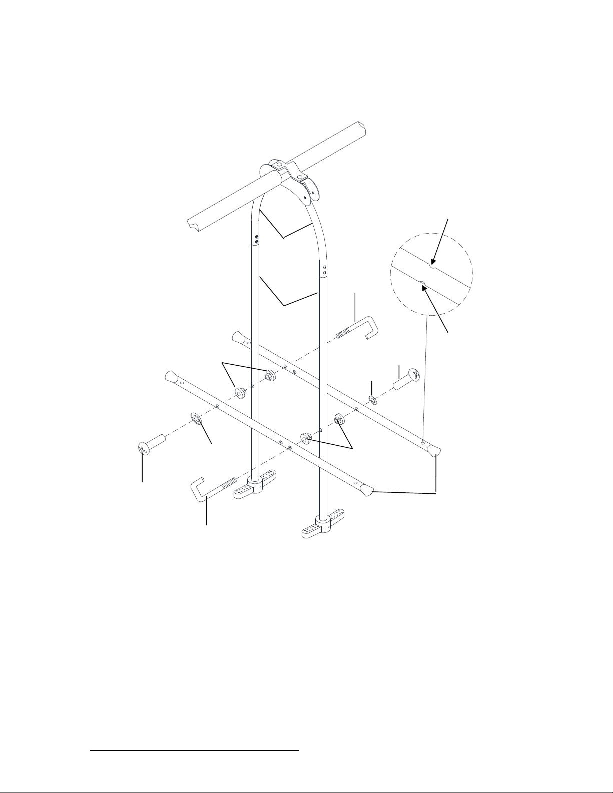
STEP 7– Glide ride assembly (continued)
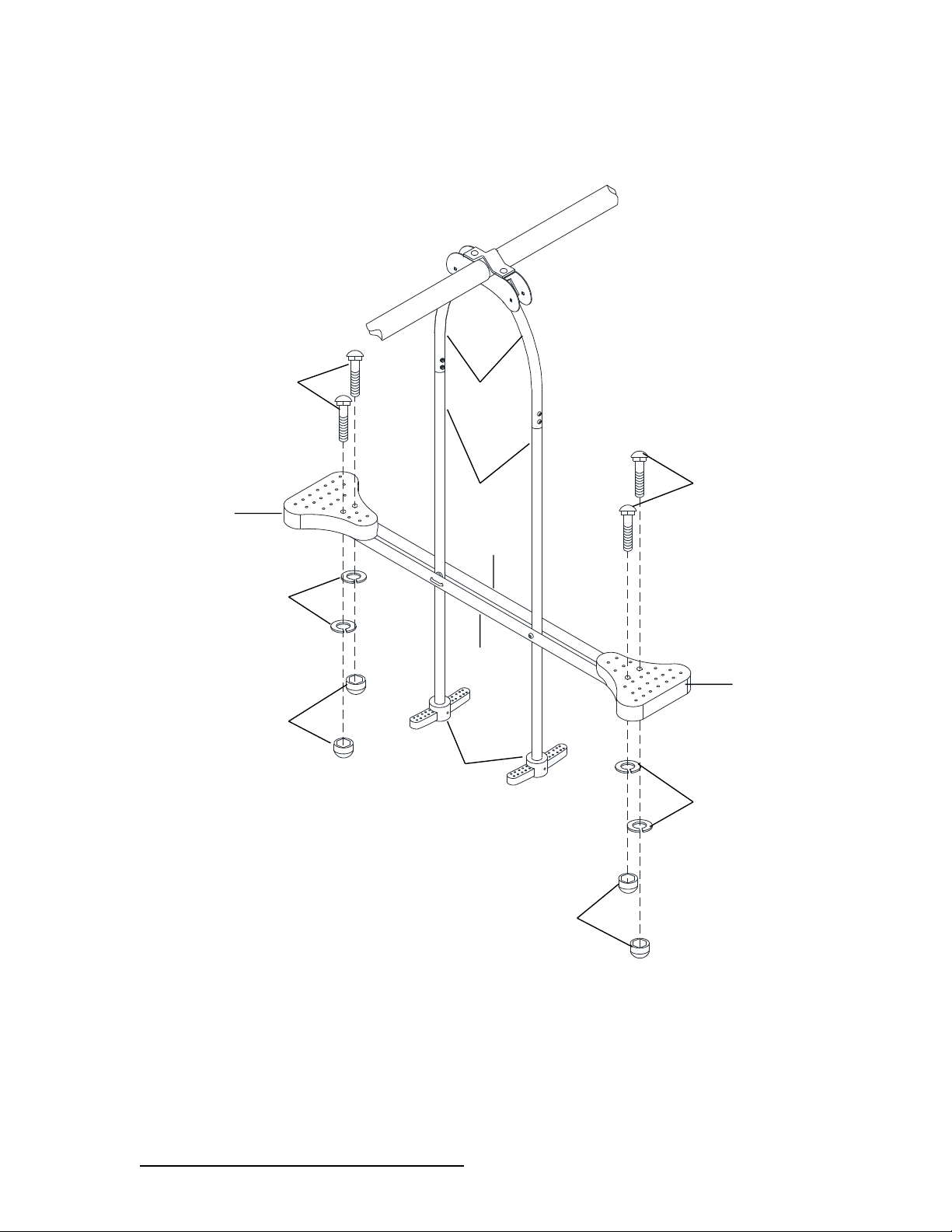
Ø Attach L3-N to L2-N on both sides and secure with N5, M3, N11 and N8.
N5
Round holes
face down
Concave holes
face up
N5
L3-N
L1-N
L2-N
M3
N8
N8
N11
N11
M3
Page 30
DO NOT RETURN TO RETAILER WHERE PURCHASED.
CONTACT XDP FOR PARTS AND SUPPORT AT 1.866.8 84 .0535 o r servic e@ xdp-recreation.com
29
STEP 8 – Glide ride assembly (continued)
Ø Attach M4 to L3-N and secure with N1, N6 and N9.
M4
L1-N
L2-N
L3-N
L3-N
M4
M5
N1
N1
N9
N9
N6
N6
Page 31
DO NOT RETURN TO RETAILER WHERE PURCHASED.
CONTACT XDP FOR PARTS AND SUPPORT AT 1.866.8 84 .0535 o r servic e@ xdp-recreation.com
30
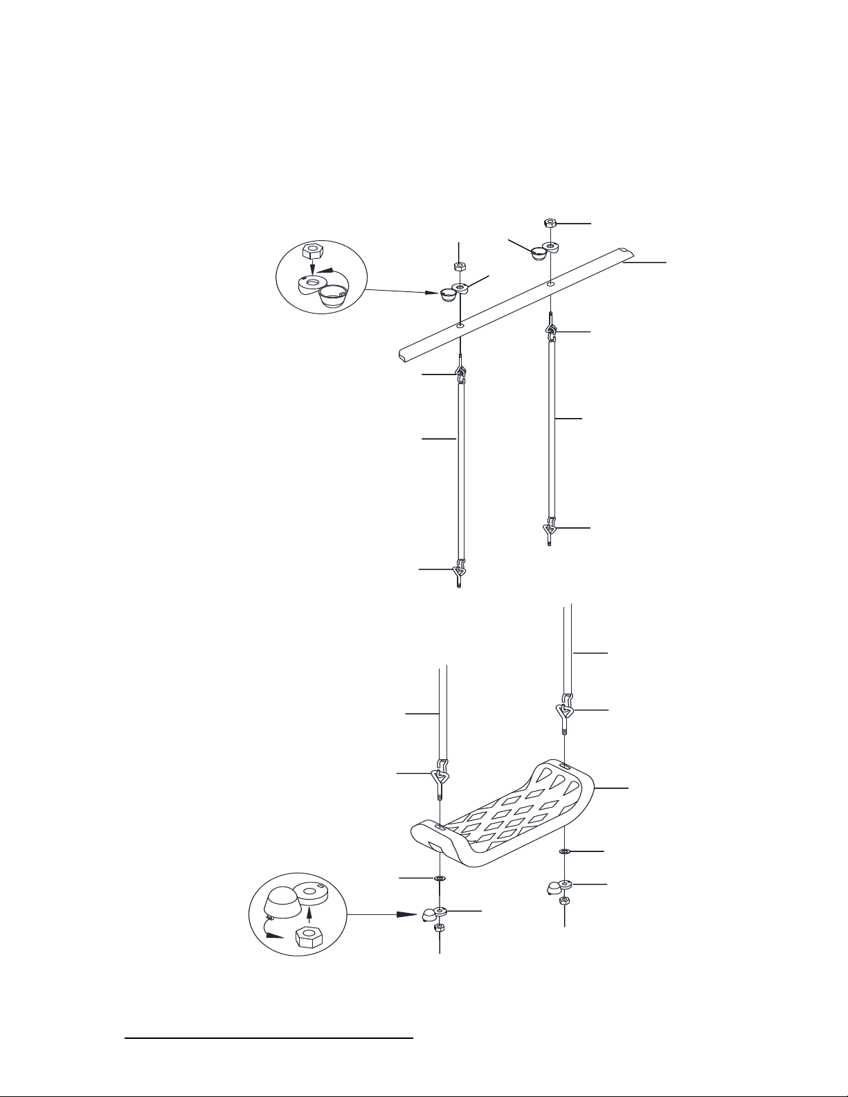
STEP 9 - Swing Seat assembly
Ø Connect swing set chains to the top bar by inserting J3 through A1 and securing with J8 and J6
as shown in Diagram A.
Ø Connect swing seat to the chains by inserting J3 through K1 and secure with J7, J9 and J6 as
shown in Diagram B.
Ø Repeat the above steps to assemble A3 in the same manner as A1.
–
DIAGRAM A
(DIAGRAM B
J6
J1
J1
J3
J3
J3
J3
J8
A1
J6
J8
K1
J3
J3
J1
J1
J6
J9
J9
J7
J7
J6
Page 32
DO NOT RETURN TO RETAILER WHERE PURCHASED.
CONTACT XDP FOR PARTS AND SUPPORT AT 1.866.8 84 .0535 o r servic e@ xdp-recreation.com
31
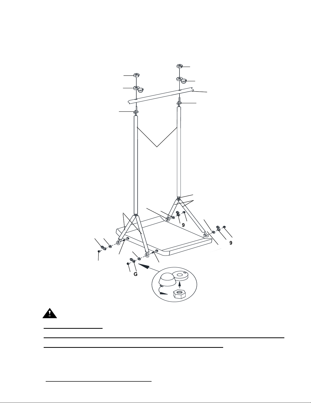
STEP 10 - Stand N Swing Assembly
Ø Insert G3 (which is pre-assembled with G1, G2 and G4) through the hole on A2. Secure using
G7 and G8 as shown in the diagram below.
Ø Insert G5 to the G6 through G7 and secure with G9 and G10 as shown in the diagram below.
N
eNOTE:
1. Do not over-tighten the nuts and bolts at every step.
2. Do not snap in the cover of plastic cap until you have finished the assembly of
each step and went back to tighten all of the nuts and bolts.
A2
G1
G5
G2
G6
G5
G3
G3
G7
G8
G9
G9
G9
G9
G10
G10
G10
G7
G7
G7
G7
G10
G2
G7
G8
G4
G4
G4
Page 33
DO NOT RETURN TO RETAILER WHERE PURCHASED.
CONTACT XDP FOR PARTS AND SUPPORT AT 1.866.8 84 .0535 o r servic e@ xdp-recreation.com
32
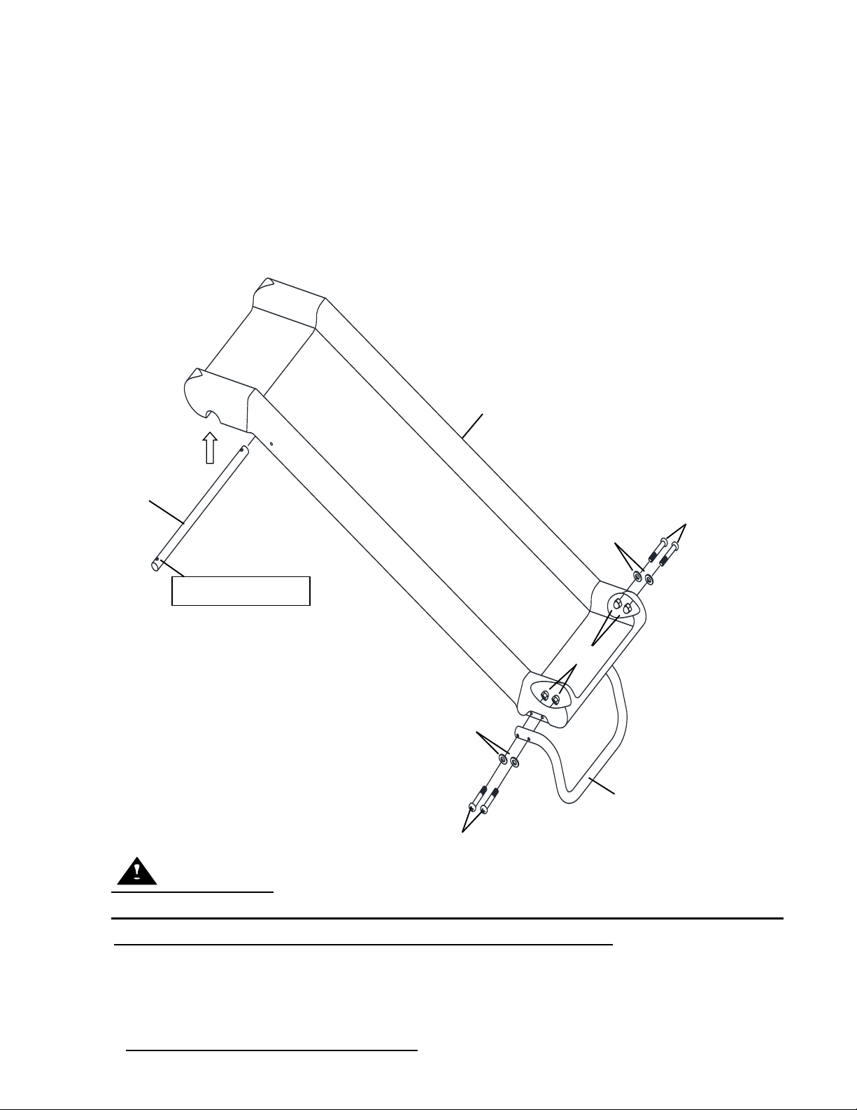
Slide assembly
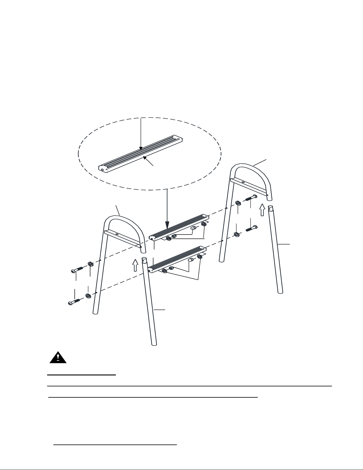
STEP 11 - Slide assembly
Ø Insert X5-N into the base of Y2.
Ø Secure using Z8, Z6 and Z4.
Ø Attach X4-N to Y2.
Ø Note: Make sure that the bolt holes face up.
i
NOTE:
1.Do not over-tighten the nuts and bolts at every step.
2.Do not snap in the cover of plastic cap until you have finished the assembly of
each step and went back to tighten all of the nuts and bolts.
Z4
Z6
Z8
Z6
Z8
X5-N
Y2
Bolt hole faces up.
X4-N
Page 34
DO NOT RETURN TO RETAILER WHERE PURCHASED.
CONTACT XDP FOR PARTS AND SUPPORT AT 1.866.8 84 .0535 o r servic e@ xdp-recreation.com
33
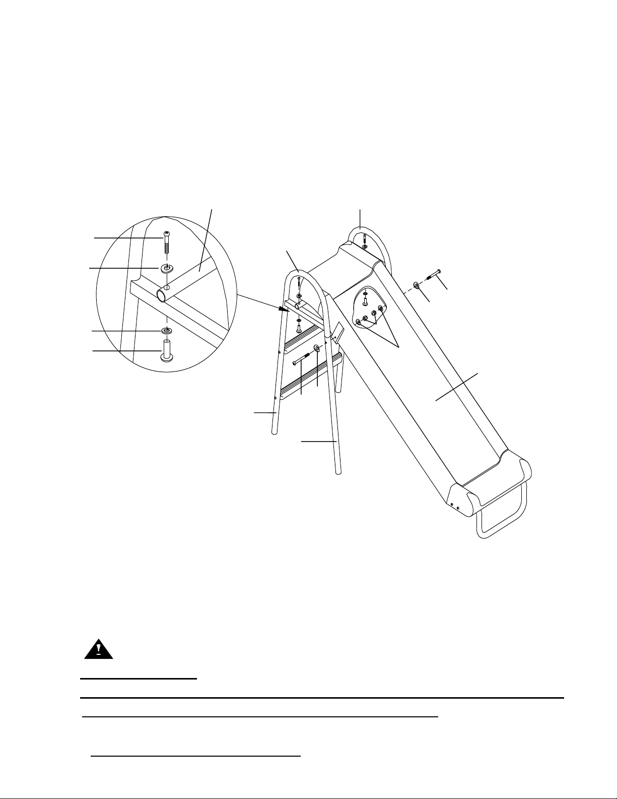
STEP 12 - Slide assembly (continued)
Ø Attach X6 to X1-N and X2-N.
Ø Secure each side using Z1, Z6 and Z4.
Ø Attach X3-N to X1-N and X2-N.
Ø Align holes and hold in position.
1
rNOTE:
1.Do not over-tighten the nuts and bolts at every step.
2.Do not snap in the cover of plastic cap until you have finished the assembly of
each step and went back to tighten all of the nuts and bolts.
X3-N
Z4
Z1
Z4
X2-N
Z6
Z6
Z6
Z6
Narrow side (Direction as
shown below)
Wide side faces the front
direction of the slide
X1-N
X3-N
X6
Z1
Page 35
DO NOT RETURN TO RETAILER WHERE PURCHASED.
CONTACT XDP FOR PARTS AND SUPPORT AT 1.866.8 84 .0535 o r servic e@ xdp-recreation.com
34
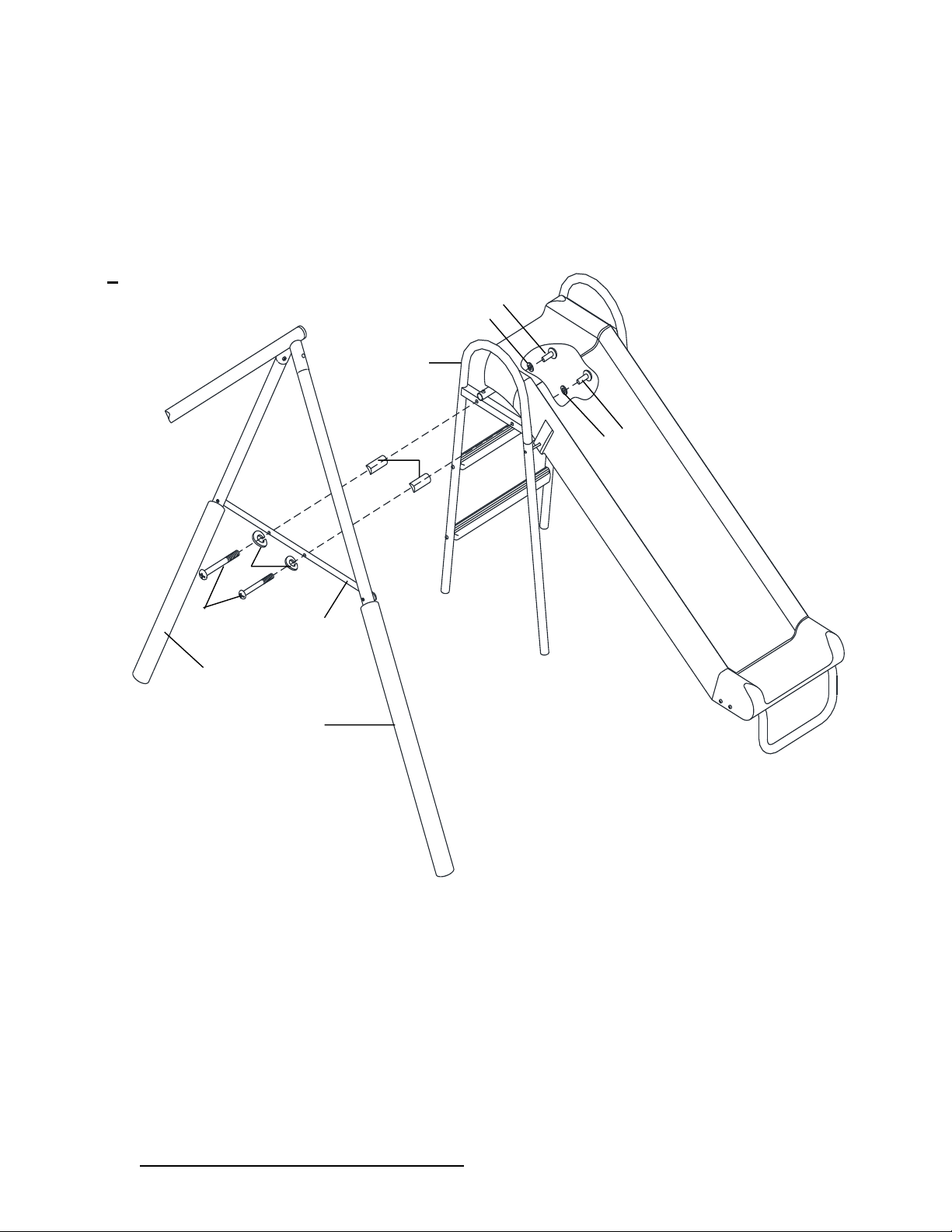
STEP 14 - Slide assembly (continued)
Ø Secure the two sides of the slide using Z2, Z6 and Z4, in the sequence shown in
the diagram.
Ø Attach X4-N to X1-N and X2-N; Secure using Z1, Z6, Z3 and Z5 as shown in the
enlarged diagram.
-
YNOTE:
1.Do not over-tighten the nuts and bolts at every step.
2.Do not snap in the cover of plastic cap until you have finished the assembly of
each step and went back to tighten all of the nuts and bolts.
X4-N
Z6
Z1
Z3
Z5
Z6
Z2
X1-N
X3-N
X1-N
X2-N
Z4
Z6
Y2
Z2
Z6
Page 36
DO NOT RETURN TO RETAILER WHERE PURCHASED.
CONTACT XDP FOR PARTS AND SUPPORT AT 1.866.8 84 .0535 o r servic e@ xdp-recreation.com
35
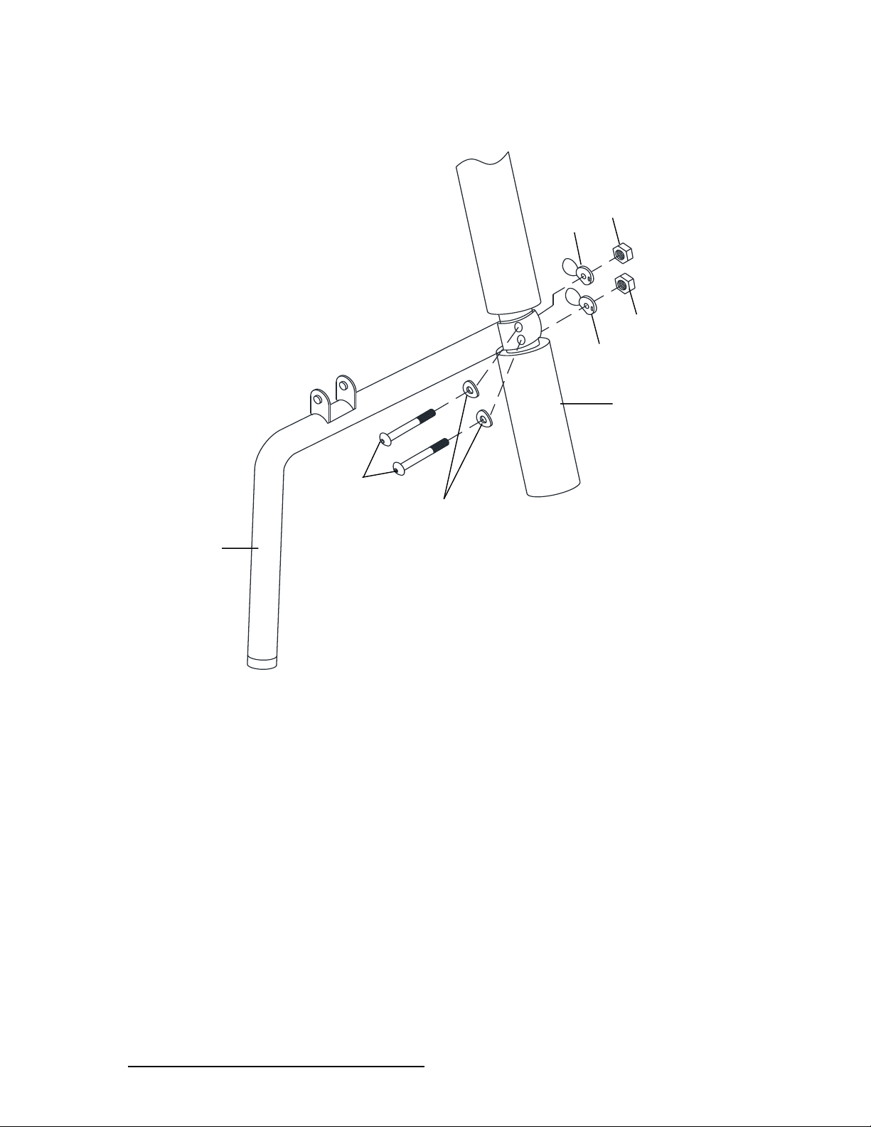
STEP 14 - Slide assembly (continued)
Ø Fit Y1 in between X1-N and A6; Secure using Y1, Z7, Z6 and Z3, Z5
c
STEP 15 - See-Saw assembly
A6
Y1
A5
A5
X1-N
Z7
Z6
Z3
Z3
Z5
Z5
Page 37
DO NOT RETURN TO RETAILER WHERE PURCHASED.
CONTACT XDP FOR PARTS AND SUPPORT AT 1.866.8 84 .0535 o r servic e@ xdp-recreation.com
36
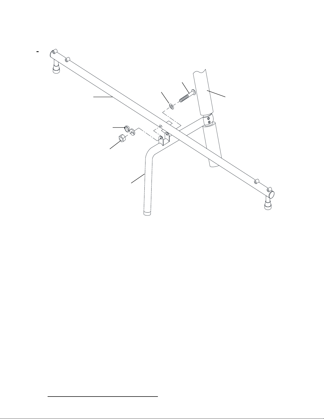
Ø Attach U20 to A5. Align the holes on U20 to the two holes on the bottom of A5 and secure using
U3, U4, U15 and U5 as shown below.
STEP 16 - See-Saw assembly (continued)
U5
U20
U15
A6
U3
U4
U15
U5
Page 38
DO NOT RETURN TO RETAILER WHERE PURCHASED.
CONTACT XDP FOR PARTS AND SUPPORT AT 1.866.8 84 .0535 o r servic e@ xdp-recreation.com
37
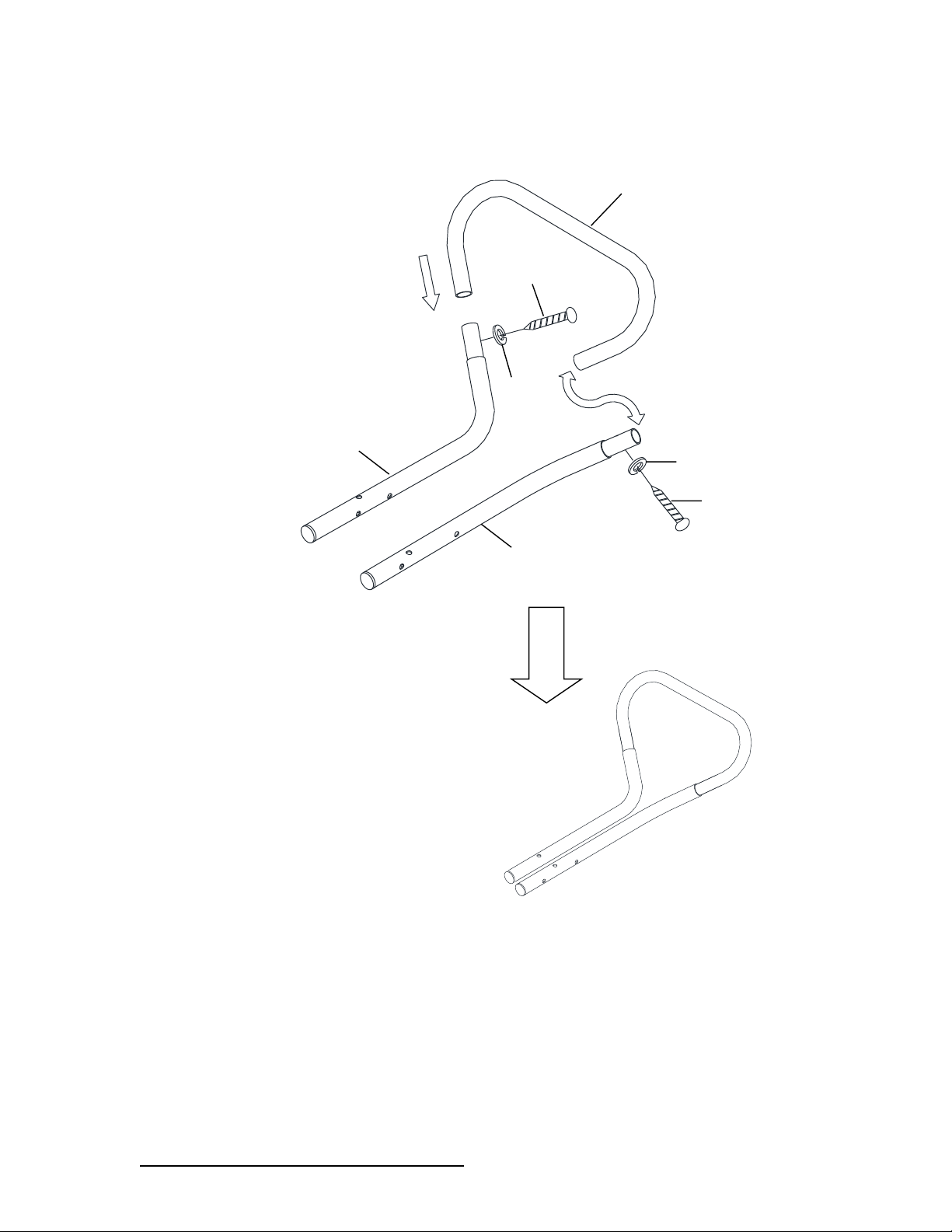
Ø Secure U17 to U20 by using U2, U14, U10 and U5 as shown below.
f
U5
U2
U14
U17
A6
U20
U10
Page 39
DO NOT RETURN TO RETAILER WHERE PURCHASED.
CONTACT XDP FOR PARTS AND SUPPORT AT 1.866.8 84 .0535 o r servic e@ xdp-recreation.com
38
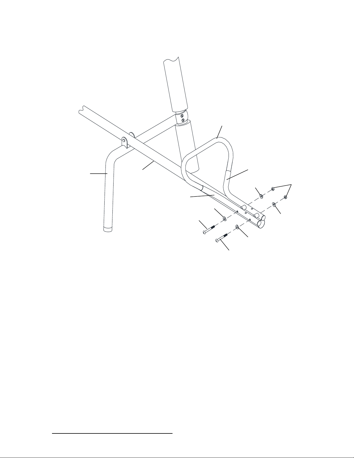
STEP 17 - See-Saw assembly (continued)
Ø Attach U18 to U19-1 and U19-2 and secure using U9 and U21.
Ø Repeat for other U18, U19-1 and U19-2.
e
i
STEP 18 - See-Saw assembly (continued)
U18
U19-2
U19-1
U9
U9
U21
U21
Page 40
DO NOT RETURN TO RETAILER WHERE PURCHASED.
CONTACT XDP FOR PARTS AND SUPPORT AT 1.866.8 84 .0535 o r servic e@ xdp-recreation.com
39
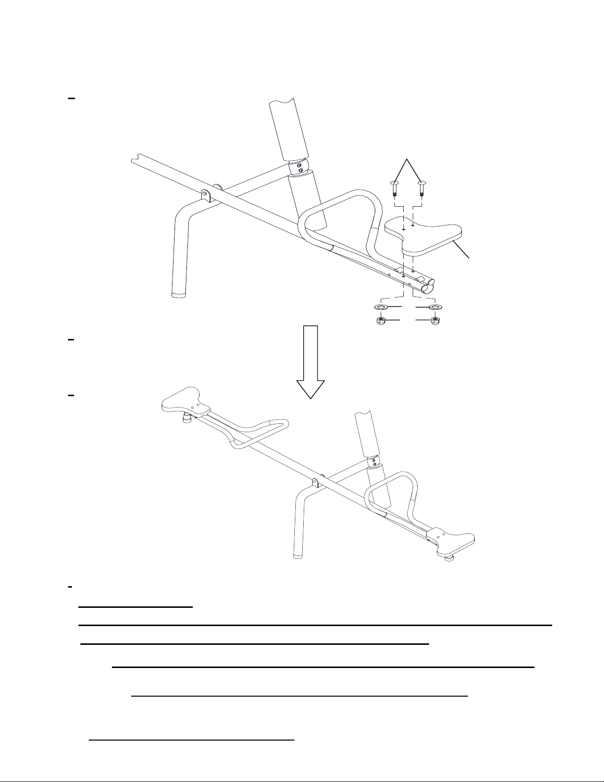
Ø Secure U19-1 & U19-2 to U17 using U1, U4 and U5 as shown below.
Ø Repeat for the other side.
m
U17
U19-1
U19-2
U1
U1
U4
U4
U4
U4
U5
U20
U18
Page 41
DO NOT RETURN TO RETAILER WHERE PURCHASED.
CONTACT XDP FOR PARTS AND SUPPORT AT 1.866.8 84 .0535 o r servic e@ xdp-recreation.com
40
STEP 19 - See-Saw assembly (continued)
Ø Secure U16 to U19-1 and U19-2 using U7, U8 and U6 as shown below.
Ø Repeat for the other side.
y
tNOTE:
1.Do not over-tighten the nuts and bolts at every step.
2.Do not snap in the cover of plastic cap until you have finished the assembly of
each step and went back to tighten all of the nuts and bolts.
Note: Make sure to go back to check all hardware and securely tighten all
bolts and nuts before using the playground equipment.
U8
U6
U16
U7
Page 42
DO NOT RETURN TO RETAILER WHERE PURCHASED.
CONTACT XDP FOR PARTS AND SUPPORT AT 1.866.8 84 .0535 o r servic e@ xdp-recreation.com
41
Congratulations! You have now completed the swing set assembly. Please
make sure to thoroughly check all parts and hardware to make sure all bolts
and nuts are well secured before using the playground equipment.
UWARNING - Do not let children use the playground equipment until it
is properly assembled and anchored.
Page 43

DO NOT RETURN TO RETAILER WHERE PURCHASED.
CONTACT XDP FOR PARTS AND SUPPORT AT 1.866.8 84 .0535 o r servic e@ xdp-recreation.com
42
Dear Customer:
Thank you for your purchase of a XDP Recreation swing set. By following the instruction manual, reading all safety
and assembly instructions, and properly anchoring your swing set in the ground, your kids will safely enjoy hours of
fun. Detailed below is our warranty covering your purchase. Please be sure to read it and contact us in the event you need
service or parts. DO NOT RETURN THE SET TO THE STORE YOU PURCHASED IT.
Sincerely,
XDP Recreation LLC
MANUFACTURER'S LIMITED WARRANTY
What does this Limited Warranty cover?
This warranty covers your XDP Recreation product for one hundred and eight (180) days against defects in material, workmanship, and rust on
painted parts which compromise the structural integrity of the product when used for the purpose intended, normal outdoor conditions, and
provided it is assembled correctly as illustrated in this manual and receives the proper care and maintenance. NOTE: Surface rust is not
covered under this warranty.
Who does this Limited Warranty Cover?
This warranty is extended only to the original purchaser with a receipt and is not transferrable.
What will XDP Recreation do?
They will provide a replacement part at no charge for any part found defective during the warranty period.
What does this warranty NOT cover?
This limited warranty does not cover XDP Recreation products which: fail due to (1) normal wear; (2) abuse and misuse; (3) improper maintenance;
(4) unauthorized repairs or incorrect parts use; or (5) are used for commercial or other income producing purposes.
(6) Acts of nature including loss or damage due to wind
How do you obtain service?
All warranty repairs must be authorized by XDP Recreation Customer Service Assistance Department before repairs are made.
IMPORTANT: There is NO NEED to return the entire unit to the store where it was purchased!
In order to obtain quick service provided by this warranty, you may call or email the details using the below contact:
Customer Support:
8:00 AM to 5:00 PM Monday through Friday (Eastern Standard Time) - 1-866-884-0535
Or email us at service@xdp-recreation.com or via fax at 1-770-886-2746
Further info can be found at www.xdp-recreation.com
REGISTER YOUR PURCHASE
PLEASE VISIT the WEBSITE at www.xdp-recreation.com to register your purchase using the manufacturer date code found on the label on
the swing set. There also is a short on-line survey which you can fill out to complete the registration.
Page 44

DO NOT RETURN TO RETAILER WHERE PURCHASED.
CONTACT XDP FOR PARTS AND SUPPORT AT 1.866.8 84 .0535 o r servic e@ xdp-recreation.com
43
 Loading...