

X-Digital System XDS PRO4-SG User Manual

XDS PRO4
Satellite Receiver
User’s Guide
PRO4 & PRO4-SG
Copyright © 2006 X-Digital Systems, Inc.
All rights reserved. No part of this document may be reproduced or transmitted in any form or by any means,
Warning!
Approved external telecom power cross protection must be
incorporated into the final installation in accordance with Annex
NAC of UL/CSA standard 60950-1. Failure to comply may result
in a fire or electric shock hazard and will void regulatory
compliance certification.
electronic or mechanical, including but not limited to photocopying, recording, or by any information storage and
retrieval system without the prior written permission from X-Digital Systems, Inc.
Warning and Disclaimer
This document is intended to provide information about installing and operating the “XDS-PRO4 DVB Satellite
Receiver”. Every effort has been made to make this document as complete and accurate as possible, but no warranty or
fitness is implied. The information is provided on an “as is” basis and X-Digital Systems shall have neither liability
nor responsibility to any person or entity with respect to any loss or damages arising from the information contained in
this document.
Acknowledge of Trademarks
Any product or corporate names used herein may be trademarks or registered trademarks, and are only used for
identification and explanation, without intent to infringe. Any terms mentioned or used that are known trademarks or
service marks have been appropriately capitalized and italicized. X-Digital Systems, Inc. cannot attest to the accuracy
of this information. Use of a term in this manual should not be regarded as affecting the validity of any trademark or
service mark.
Printed in the United States of America
X-Digital Systems, Inc.
9727 Pacific Heights Blvd.
Suite 200
San Diego, CA 92121
Patent Pending
X-Digital Systems, Inc., DVB Satellite Receiver – Patents Pending
THIS DEVICE COMPLIES WITH PART 15 OF THE FCC RULES. OPERATION OF THIS
DEVICE IS SUBJECT TO THE FOLLOWING TWO CONDITIONS: (1) THIS DEVICE MAY
NOT CAUSE HARMFUL INTERFERENCE, AND (2) THIS DEVICE MUST ACCEPT ANY
INTERFERENCE RECEIVED, INCLUDING INTERFERENCE THAT MAY CAUSE
UNDESIRED OPERATION.
1226 R830002-1060 XDS Pro Users Guide 1/11/2010
Rev A

TABLE OF CONTENTS
1 INTRODUCTION ...................................................................................................... 5
1.1 Important Information ......................................................................................... 5
1.2 Hardware Upgradeability .................................................................................... 5
1.3 Hardware Versatility ........................................................................................... 5
1.4 Network Management System ............................................................................ 6
2 GETTING STARTED ................................................................................................ 7
2.1 Unpacking the Receiver ...................................................................................... 7
2.1.1 List of Contents ........................................................................................... 7
2.2 Safety Precautions ............................................................................................... 7
2.2.1 Excessive Temperature ............................................................................... 7
2.2.2 Proper Ventilation ....................................................................................... 8
2.2.3 Heat, Humidity, and Dust ........................................................................... 8
2.2.4 Power Cord Cabling .................................................................................... 8
2.2.5 Proper Grounding........................................................................................ 8
2.2.6 Circuit Overloading .................................................................................... 8
2.2.7 Foreign Objects ........................................................................................... 9
2.3 Physical Installation of the Receiver................................................................... 9
2.3.1 Rack Mounting the Receiver ...................................................................... 9
2.3.2 Uneven Loading of Rack ............................................................................ 9
2.4 Connecting the Receiver to a Satellite Dish ....................................................... 9
2.4.1 DC Voltage Requirement .......................................................................... 10
2.4.2 Warnings About Shorting DC ................................................................... 10
3 QUICK START ........................................................................................................ 11
3.1 General Guidelines............................................................................................ 11
4 FRONT PANEL OPERATIONS .............................................................................. 12
4.1 Status LEDs ...................................................................................................... 12
4.1.1 The Power LED ........................................................................................ 12
4.1.2 The Signal LED ........................................................................................ 12
4.1.3 The Update LED ....................................................................................... 12
4.1.4 The Fault LED .......................................................................................... 12
4.2 The LCD Display and User Interface ............................................................... 13
The Main Menu Options ........................................................................................... 13
4.2.1 The Status Sub-Menus .............................................................................. 14
4.2.2 The SETUP Sub-Menus ............................................................................ 15
4.2.2.1 The SETUP:NETWORK Sub-Menus................................................... 16
4.2.2.2 The SETUP:TUNER Sub-Menus ......................................................... 17
4.2.3 The AUDIO PORTS Sub-Menus ............................................................. 18
4.2.3.1 The AUDIO PORTS:SETUP Sub-Menus ............................................ 19
5 ETHERNET SETUP ................................................................................................. 21
5.1 Connecting the Cables ...................................................................................... 21
5.2 Using DHCP or Static IP Addresses ................................................................. 21
5.3 Assigning a TCP/IP Address ............................................................................ 21
5.4 Assigning a Subnet Mask.................................................................................. 22
5.5 Assigning a Default Gateway ........................................................................... 22
1226 R830002-1060 XDS Pro Users Guide 1/11/2010
Rev A

5.6 Proxy Server Configuration .............................................................................. 22
5.7 DNS Server Configuration ................................................................................ 22
6 RECEIVER WEB INTERFACE .............................................................................. 23
6.1 The General Menu ............................................................................................ 23
6.1.1 The Status Tab .......................................................................................... 24
6.1.2 The Tuner Tab........................................................................................... 25
6.1.3 The Setup Tab ........................................................................................... 26
6.2 *The Programming Menu ................................................................................. 27
6.2.1 *The Programs Tab ................................................................................... 27
6.2.2 *The Recordings Tab ................................................................................ 28
6.3 *The Content Menu .......................................................................................... 29
6.3.1 *The Audio Tab ........................................................................................ 29
6.3.2 *The Traffic Tab ....................................................................................... 29
6.3.3 *The All Tab ............................................................................................. 30
7 AFFILIATE WEB INTERFACE ............................................................................. 31
7.1 *Accessing and Logging In .............................................................................. 31
7.2 *Play Scheduling .............................................................................................. 31
7.3 Changing the Receiver‟s Time Zone ................................................................ 32
8 MONITOR AND CONTROL INTERFACE ........................................................... 33
8.1 Setting up a Console Connection ...................................................................... 33
8.2 Console Commands .......................................................................................... 34
9 SPECIFICATIONS ................................................................................................... 38
9.1 Receiver Interface Specification ....................................................................... 38
9.2 Mechanical/Electrical Specification ................................................................. 38
9.3 Environmental Specifications ........................................................................... 38
9.4 M&C Interface Connector Pin-Outs ................................................................. 39
9.5 Relay Outputs.................................................................................................... 40
9.6 Analog Audio Output ........................................................................................ 41
9.7 Analog Audio Input .......................................................................................... 42
9.8 *Digital Audio Output ...................................................................................... 43
9.9 *PAD/ASYNC Output Port .............................................................................. 44
9.10 Ethernet Port ..................................................................................................... 44
9.11 Modem (POTS) Port ......................................................................................... 44
9.12 RF Input Parameters ......................................................................................... 45
1226 R830002-1060 XDS Pro Users Guide 1/11/2010
Rev A

Note!
The note icon identifies information for the proper
operation of your equipment, including helpful hints,
shortcuts, or important reminders
Caution!
The caution icon identifies information that requires
careful attention in order to prevent equipment damage.
Warning!
The warning icon identifies a procedure or practice that
could result in personal injury if not performed correctly.
1 INTRODUCTION
Welcome to the future of digital audio for the radio industry. This User‟s Guide is your
handbook for the X-Digital PRO4 digital audio receiver. This receiver is equipped to
deliver multiple audio services in high quality digital audio for your radio station. It has
been designed to make use of all the digital communication features of today, and to be
upgraded to take advantage of the technologies of tomorrow.
1.1 Important Information
Throughout this guide, you will find icons designed to help you quickly spot important
information:
1.2 Hardware Upgradeability
X-Digital Systems, Inc. can upgrade its main control software and audio decoder
algorithms over-the-air. This ensures that your receiver will always have the most up to
the minute features and functionality.
1.3 Hardware Versatility
The XDS PRO4 can deliver audio received via satellite over any one of its four balanced
output ports. Additionally, content can be received and stored locally for later use. This
content can originate from a real time satellite broadcast, from a high speed satellite IP
distribution channel, or can be retrieved via the Internet over the Ethernet port, if so
configured.
1226 R830002-1060 XDS Pro Users Guide 1/11/2010
Rev A

1.4 Network Management System
The PRO4 satellite receiver has been specifically designed so that its output can be
controlled via one central web application. This application is called the Network
Management System, or NMS. From the NMS, the receiver can be monitored and
managed, and the user can set a schedule of live and delayed programs for each output
port. The NMS will also coordinate file transfers to store sound, data, or hardware
updates directly to the PRO4‟s internal hard drive. The NMS will also come equipped
with an advanced event logging system ensuring that any technical problems will be
accompanied by a full history so that causes of problems may be easily identified and
eliminated.
1226 R830002-1060 XDS Pro Users Guide 1/11/2010
Rev A
2 GETTING STARTED
Item
Quantity
Receiver
1
Power Cord
1
Quick Start Guide
1
Installation Kit (Optional)
1
Caution!
The following sections provide a list of general hazards to be
avoided for safe, reliable use of the PRO4 receiver.
Please take a few minutes to read through the User‟s Guide prior to setting up and using
the unit. If you are in a hurry, there is a Quick Start section below, but please be sure to
consult this section at your earliest convenience.
2.1 Unpacking the Receiver
Upon receiving your PRO4 Receiver, ensure that all of the necessary parts have been
included.
2.1.1 List of Contents
Table 1 lists the items included in the PRO4 shipping box.
Table 1. Packaging List
2.2 Safety Precautions
2.2.1 Excessive Temperature
The PRO4 receiver has been designed to operate safely and reliably in an ambient
temperature of 0○C to 50○C. We expect the system to operate without a need for a fan in
air conditioned locations. The fan will be electronically controlled via temperature
sensor. This will allow the unit to operate under less than optimal conditions. However,
once the receiver is located in a closed or rack environment, the ambient temperature may
be greater than room temperature. Please take this into consideration when installing the
receiver, making sure that the ambient temperature around the receiver does not exceed
the temperature range 0○C to 50○C.
1226 R830002-1060 XDS Pro Users Guide 1/11/2010
Rev A

2.2.2 Proper Ventilation
Warning!
Make sure all power strips are properly grounded.
Air vents on the side and rear of the receiver are provided to ensure proper air flow
through the receiver unit. In order to ensure proper operation the PRO4 receiver should
be located such that its ventilation is not impeded. In a rack environment, at least two
inches on the sides and at least 5 inches in the rear should be provided. Proper ventilation
will help ensure the receiver performs both safely and efficiently.
2.2.3 Heat, Humidity, and Dust
In order to avoid unnecessary internal damage, avoid placing the receiver next to external
heat sources such as heaters, direct sunlight, heating ducts, etc. Also avoid locations of
high humidity, dust, and vibration.
2.2.4 Power Cord Cabling
Avoid running the power cord across places of high traffic where it can be crimped or
tripped over. Make sure the cords are securely fastened to both the wall outlet or power
strip, and the back of the receiver. Do not place objects on or leaning against power
cords.
2.2.5 Proper Grounding
When the receiver is installed, make sure that the antenna and coaxial cable are properly
grounded to avoid static build up and voltage spikes which may occur due to lightning or
other types of power surges. Proper earth grounding of the rack system should be
maintained at all times, with special attention paid to any connections which go through
power strips.
2.2.6 Circuit Overloading
The PRO4 receiver can draw up to 0.5 Amps at 120VAC as indicated on the back of the
receiver. When adding the receiver to an already existing rack setup, take care to ensure
the maximum current rating of the circuit is not exceeded.
1226 R830002-1060 XDS Pro Users Guide 1/11/2010
Rev A

2.2.7 Foreign Objects
Warning!
Inserting any type of foreign object into the ventilation holes of the
receiver can result in shock or serious injury of the operator.
Caution!
Do not paint mounting ears; it hinders the grounding path from
the receiver to the rack.
Caution!
Uneven loading may cause the rack to be unstable and
hazardous.
If a foreign object is inserted into the receiver, immediately power down the receiver and
contact X-Digital Systems technical support. Do not open the receiver, as doing so will
void the receiver‟s warranty.
2.3 Physical Installation of the Receiver
The following section will guide you through the physical installation of the PRO4
receiver. The receiver should be installed in a standard 19-inch rack.
2.3.1 Rack Mounting the Receiver
The PRO4 receiver has been specifically designed to fit into a 19-inch rack. There are
four screw holes provided on the front panel to directly mount the receiver in the rack.
All four screws must be in place after installing the receiver.
2.3.2 Uneven Loading of Rack
When installing the PRO4 receiver into a rack, make sure to place heavier pieces of
equipment on the bottom and lighter pieces on the top.
2.4 Connecting the Receiver to a Satellite Dish
This section contains information required for connection your PRO4 receiver to a
satellite hookup.
1226 R830002-1060 XDS Pro Users Guide 1/11/2010
Rev A

2.4.1 DC Voltage Requirement
Caution!
If the LNB Voltage mode is ON enabled, be careful not to short
the signal. The voltage on this line is approximately +24V DC.
You may need to have the PRO4 receiver supply DC voltage to either an LNB or a block
down-converter (used after an LNA). If this is the case, the user must change the
receiver‟s LNB on/off settings using the front panel display. For directions on how to use
the front panel display, see Chapter 4 of this manual. If, however, you have another
receiver that receives the L-Band version of the satellite signal (9500-14500MHz) then
you may use a splitter with DC blocking circuitry to get the signal to the PRO4 receiver.
In this case, set the LNB Voltage setting to off.
2.4.2 Warnings About Shorting DC
If the DC Voltage is shorted during installation, transient voltage may damage the
Demodulator. In the case of a short, over-current protection circuitry will shut down the
LNB supply. When this occurs, it is important to disconnect the receiver as soon as
possible. If there is a “dead” short in the cable connecting the receiver to the satellite
dish, the unit will not function properly. Remove the power cord from the rear of the unit
and then check the cable connecting the receiver to the satellite dish to make sure it has
not been damaged and is installed correctly. Finally, reinstall the power cord and proceed
with unit setup.
1226 R830002-1060 XDS Pro Users Guide 1/11/2010
Rev A

3 QUICK START
This quick start is designed to get your XDS PRO4 receiver up and running as quickly as
possible. Please refer to the full Quick Start Guide packaged with your receiver.
3.1 General Guidelines
Review this guide in its entirety before installing your XDS receiver. Also, follow these
instructions before calling support.
Make all satellite RF, data (LAN/WAN) and audio connections prior to applying AC
power to the XDS receiver.
It is strongly recommended to use a Phase Locked Loop (PLL) LNB for your new
XDS receiver. The Local Oscillator (LO) stability of your LNB should not be above
(worse than) 25kHz.
If this XDS receiver is designated to supply DC power to the LNB at your dish, be
sure to turn on the LNB voltage on the front panel menu AFTER the LNB is
connected (See Satellite RF Connection section 1.2 on page 3).
Your new XDS receiver is delivered with a parts kit that includes two 6-foot RG-6
cables and an L-band splitter that allows DC power to pass through one port.
X-digital PRO4-SG are supplied with two relay adaptor cables (DB37 to DB15) to
match existing cabling that may exist to support a form/fit and function of the SGIII
X-Digital Systems urges stations to use an Uninterruptible Power Supply (UPS) for
the XDS receiver for equipment protection from power spikes or brownouts. Also
consider lightning protection if you are located in an area susceptible to frequent
lightning storms. Surge suppressors do not provide sufficient protection.
1226 R830002-1060 XDS Pro Users Guide 1/11/2010
Rev A

4 FRONT PANEL OPERATIONS
The PRO4 Receiver‟s Front Panel is equipped with a 128x64 pixel LCD display, four
status LEDs; which indicate power, signal, update, and fault; and eight buttons: 1, 2, 3,
left (◄), right (►), up (▲), down (▼), and SET. Using this interface a user may
navigate through the PRO4‟s hierarchical menu to view, modify, and save receiver
settings. The four status LEDs serve as a quick reference for the current state of the
receiver.
4.1 Status LEDs
There are four status light emitting diodes, each indicating a specific property of the
receiver. The following sections state their significance.
4.1.1 The Power LED
The POWER LED is on when the unit is plugged in and there is no problem with the
internal circuitry.
4.1.2 The Signal LED
The SIGNAL LED is used to indicate when the receiver has locked onto a signal or not.
If the signal LED is a solid green, the receiver is locked. Otherwise, the light will be off.
4.1.3 The Update LED
The UPDATE led indicates a software download/upgrade is in progress. When it is
blinking slowly (once per second), the download is in process. When it blinks fast (3x per
second), an upgrade has been successful and the receiver should be rebooted at a
convenient time (when audio is off air). The update LED will also be blinking if you
haven‟t activated your receiver unit with the NMS. See the Quick Start guide in Chapter
3 for activation instructions.
4.1.4 The Fault LED
The FAULT LED has three possible states. A red fault LED indicates that there is an
active fault condition affecting the receiver. A green fault LED indicates that there is no
active fault, but that there is either an active warning or a past fault in the fault history.
An off fault LED indicates that all is well and there are no past faults detected. The
STATUS menu (described below) will give you details as to which faults are active.
1226 R830002-1060 XDS Pro Users Guide 1/11/2010
Rev A

1
4.2 The LCD Display and User Interface
The PRO4 Receiver comes equipped with a 128x64 pixel LCD on its front panel which
allows the user to view, modify, and save receiver settings. The navigation of the PRO4
receiver‟s menu hierarchy is simple:
- To cycle through the possible sub-menus, press the ◄ or ► buttons.
- To navigate into the currently selected sub-menu, press the ▼ button.
- To navigate back up into a higher level of the menu hierarchy, press the ▲
button.
- Once you have navigated to a menu which allows you to edit settings, use the ▲
and ▼ buttons to highlight options, and the set button, to pick an option.
-
The Main Menu Options
When the receiver‟s front panel is not being used, the idle screen featuring the X-Digital
Systems 1 logo will be displayed. There are two important statistics displayed on this
front logo screen: EB, energy per bit relative to noise floor, which is a quantitative
measure of signal quality; and AG, automatic gain, which is an indicator of the signal
level. Both of these quantities serve to describe the quality of the satellite signal and
should be used as a guide when positioning the satellite dish. Better signals have better
separation between the data and noise floor, and thus a higher EB. EB range is 0 - 18.
The receiver will fade in and out below 5 dB Eb/No, and loose lock completely at around
3.5 dB. A powerful signal will have a high AG (indicating little amplification is
required) while a weak signal will have a low AG (indicating unit is amplifying signal).
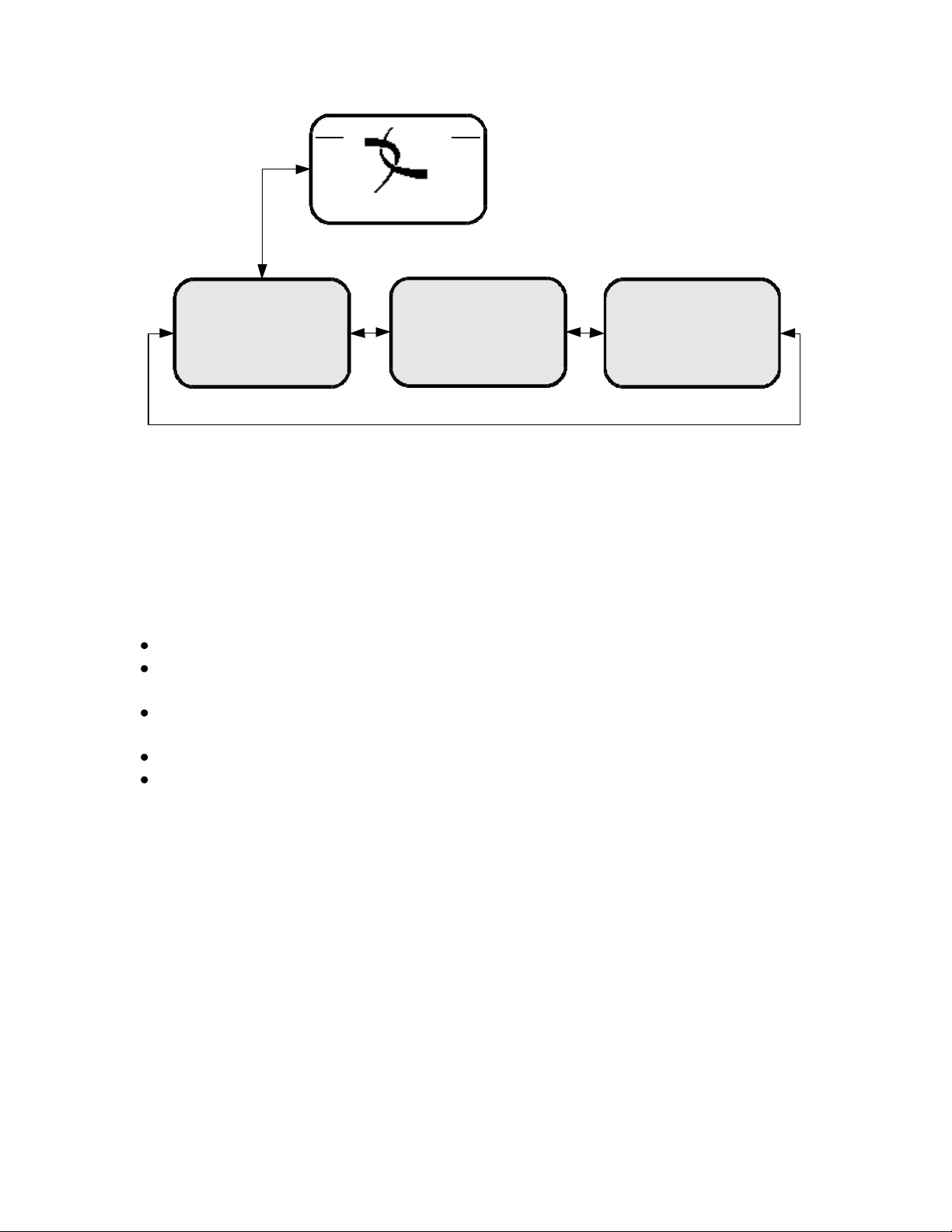
Once the ▼ button is pressed, the receiver will navigate into its main menu options.
These options are: STATUS, SETUP, and AUDIO PORTS. Continually pressing ◄ (or
►) will cycle through these three main menus. Pressing ▼ or SET will navigate into
whichever one of these three options happen to be currently selected.
The X-Digital logo may be replaced by your broadcaster‟s logo.
1226 R830002-1060 XDS Pro Users Guide 1/11/2010
Rev A
U/D
L/R
L/R
L/R
EB AG
XDS PRO4
XDS PRO4
Status
XDS PRO4
Setup
XDS PRO4
Audio Ports
4.2.1 The Status Sub-Menus
From the Status menu, the user can navigate through five sub-menus, each of them offers
various status-related information. From any of these sub-menus pressing the ▲ button
will being you back to the main menu options. The different sub-menus available in
Status are:
Active Faults: describes any active faults that may be affecting the receiver.
Fault History: offers a list of past faults which may have occurred. Pushing 3 will
clear the fault history.
Environment: indicates whether the internal fans are functioning inside the unit, and
the internal temperature of the receiver unit.
Power Status: readings on the various voltage levels inside the receiver.
Storage Status: gives an indication of the internal storage drive usage in the receiver.
1226 R830002-1060 XDS Pro Users Guide 1/11/2010
Rev A
 Loading...