

Page 1
XDS PRO4
Satellite Receiver
User’s Guide
Page 2

Copyright © 2006 X-Digital Systems, Inc.
All rights reserved. No part of this document may be reproduced or transmitted in any form or by any means,
electronic or mechanical, including but not limited to photocopying, recording, or by any information storage and
retrieval system without the prior written permission from X-Digital Systems, Inc.
Warning and Disclaimer
This document is intended to provide information about installing and operating the “XDS-PRO4 DVB Satellite
Receiver”. Every effort has been made to make this document as complete and accurate as possible, but no warranty or
fitness is implied. The information is provided on an “as is” basis and X-Digital Systems shall have neither liability
nor responsibility to any person or entity with respect to any loss or damages arising from the information contained in
this document.
Acknowledge of Trademarks
Any product or corporate names used herein may be trademarks or registered trademarks, and are only used for
identification and explanation, without intent to infringe. Any terms mentioned or used that are known trademarks or
service marks have been appropriately capitalized and italicized. X-Digital Systems, Inc. cannot attest to the accuracy
of this information. Use of a term in this manual should not be regarded as affecting the validity of any trademark or
service mark.
Printed in the United States of America
X-Digital Systems, Inc.
9727 Pacific Heights Blvd.
Suite 200
San Diego, CA 92121
Patent Pending
X-Digital Systems, Inc., DVB Satellite Receiver – Patents Pending
Warning!
Approved external telecom power cross protection must be
incorporated into the final installation in accordance with Annex
NAC of UL/CSA standard 60950-1. Failure to comply may result
in a fire or electric shock hazard and will void regulatory
compliance certification.
THIS DEVICE COMPLIES WITH PART 15 OF THE FCC RULES. OPERATION OF THIS
DEVICE IS SUBJECT TO THE FOLLOWING TWO CONDITIONS: (1) THIS DEVICE MAY
NOT CAUSE HARMFUL INTERFERENCE, AND (2) THIS DEVICE MUST ACCEPT ANY
INTERFERENCE RECEIVED, INCLUDING INTERFERENCE THAT MAY CAUSE
UNDESIRED OPERATION.
2
X-Digital Systems
XDS-PRO4
R830001-1060 Rev B
Page 3

TABLE OF CONTENTS
1 INTRODUCTION ...................................................................................................... 5
1.1 Important Information......................................................................................... 5
1.2 Hardware Upgradeability.................................................................................... 5
1.3 Hardware Versatility........................................................................................... 5
1.4 Network Management System............................................................................ 6
2 GETTING STARTED ................................................................................................ 7
2.1 Unpacking the Receiver...................................................................................... 7
2.1.1 List of Contents........................................................................................... 7
2.2 Safety Precautions............................................................................................... 7
2.2.1 Excessive Temperature ............................................................................... 7
2.2.2 Proper Ventilation....................................................................................... 8
2.2.3 Heat, Humidity, and Dust ........................................................................... 8
2.2.4 Power Cord Cabling.................................................................................... 8
2.2.5 Proper Grounding........................................................................................ 8
2.2.6 Circuit Overloading .................................................................................... 8
2.2.7 Foreign Objects........................................................................................... 9
2.3 Physical Installation of the Receiver................................................................... 9
2.3.1 Rack Mounting the Receiver ...................................................................... 9
2.3.2 Uneven Loading of Rack ............................................................................ 9
2.4 Connecting the Receiver to a Satellite Dish ....................................................... 9
2.4.1 DC Voltage Requirement.......................................................................... 10
2.4.2 Warnings About Shorting DC................................................................... 10
3 QUICK START ........................................................................................................ 11
3.1 General Guidelines............................................................................................ 11
4 FRONT PANEL OPERATIONS.............................................................................. 12
4.1 Status LEDs ...................................................................................................... 12
4.1.1 The Power LED ........................................................................................ 12
4.1.2 The Signal LED ........................................................................................ 12
4.1.3 The Update LED ....................................................................................... 12
4.1.4 The Fault LED .......................................................................................... 12
4.2 The LCD Display and User Interface ............................................................... 13
The Main Menu Options........................................................................................... 13
4.2.1 The Status Sub-Menus .............................................................................. 14
4.2.2 The SETUP Sub-Menus............................................................................ 15
4.2.2.1 The SETUP:NETWORK Sub-Menus................................................... 16
4.2.2.2 The SETUP:TUNER Sub-Menus ......................................................... 17
4.2.3 The AUDIO PORTS Sub-Menus ............................................................. 18
4.2.3.1 The AUDIO PORTS:SETUP Sub-Menus ............................................ 19
5 ETHERNET SETUP................................................................................................. 21
5.1 Connecting the Cables ...................................................................................... 21
5.2 Using DHCP or Static IP Addresses................................................................. 21
5.3 Assigning a TCP/IP Address ............................................................................ 21
5.4 Assigning a Subnet Mask.................................................................................. 22
5.5 Assigning a Default Gateway ........................................................................... 22
5.6 Proxy Server Configuration .............................................................................. 22
3
X-Digital Systems
XDS-PRO4
R830001-1060 Rev B
Page 4

5.7 DNS Server Configuration................................................................................ 22
6 RECEIVER WEB INTERFACE .............................................................................. 23
6.1 The General Menu ............................................................................................ 23
6.1.1 The Status Tab .......................................................................................... 23
6.1.2 The Tuner Tab........................................................................................... 24
6.1.3 The Setup Tab ........................................................................................... 25
6.1.4 The Relays Tab ......................................................................................... 26
6.2 The Programming Menu ................................................................................... 27
6.2.1 The Programs Tab..................................................................................... 27
6.2.2 The Recordings Tab.................................................................................. 28
6.3 The Content Menu ............................................................................................ 29
6.3.1 The Audio Tab .......................................................................................... 29
6.3.2 The Traffic Tab ......................................................................................... 29
6.3.3 The All Tab ............................................................................................... 30
7 AFFILIATE WEB INTERFACE ............................................................................. 31
7.1 Accessing and Logging In ................................................................................ 31
7.2 Play Scheduling ................................................................................................ 31
7.3 Changing the Relay Mappings.......................................................................... 32
7.4 Changing the Receiver’s Time Zone ................................................................ 32
8 MONITOR AND CONTROL INTERFACE ........................................................... 34
8.1 Setting up a Console Connection...................................................................... 34
8.2 Console Commands .......................................................................................... 35
9 SPECIFICATIONS................................................................................................... 39
9.1 Receiver Interface Specification ....................................................................... 39
9.2 Mechanical/Electrical Specification ................................................................. 39
9.3 Environmental Specifications ........................................................................... 39
9.4 M&C Interface Connector Pin-Outs ................................................................. 40
9.5 Relay Outputs.................................................................................................... 41
9.6 Analog Audio Output........................................................................................ 42
9.7 Analog Audio Input .......................................................................................... 43
9.8 Digital Audio Output ........................................................................................ 44
9.9 PAD/ASYNC Output Port ................................................................................ 45
9.10 Ethernet Port ..................................................................................................... 45
9.11 Modem (POTS) Port ......................................................................................... 45
9.12 RF Input Parameters ......................................................................................... 46
4
X-Digital Systems
XDS-PRO4
R830001-1060 Rev B
Page 5

1 INTRODUCTION
Welcome to the future of digital audio for the radio industry. This User’s Guide is your
handbook for the X-Digital PRO4 digital audio receiver. This receiver is equipped to
deliver multiple audio services in high quality digital audio for your radio station. It has
been designed to make use of all the digital communication features of today, and to be
upgraded to take advantage of the technologies of tomorrow.
1.1
Important Information
Throughout this guide, you will find icons designed to help you quickly spot important
information:
Note!
Caution!
Warning!
The note icon identifies information for the proper
operation of your equipment, including helpful hints,
shortcuts, or important reminders
The caution icon identifies information that requires
careful attention in order to prevent equipment damage.
The warning icon identifies a procedure or practice that
could result in personal injury if not performed correctly.
1.2
Hardware Upgradeability
X-Digital Systems, Inc. can upgrade its main control software and audio decoder
algorithms over-the-air. This ensures that your receiver will always have the most up to
the minute features and functionality.
1.3
Hardware Versatility
The XDS PRO4 can deliver audio received via satellite over any one of its four balanced
output ports. Additionally, content can be received and stored locally for later use. This
content can originate from a real time satellite broadcast, from a high speed satellite IP
distribution channel, or can be retrieved via the Internet over the Ethernet port, if so
configured.
5
X-Digital Systems
XDS-PRO4
R830001-1060 Rev B
Page 6

1.4
Network Management System
The PRO4 satellite receiver has been specifically designed so that its output can be
controlled via one central web application. This application is called the Network
Management System, or NMS. From the NMS, network managers will be able to create
play schedules consisting of radio programs and any combination of network, regional, or
off-time commercial spots. The NMS will also coordinate file transfers to store sound,
data, or hardware updates directly to the PRO4’s internal hard drive. The NMS will also
come equipped with an advanced event logging system ensuring that any technical
problems will be accompanied by a full history so that causes of problems may be easily
identified and eliminated.
6
X-Digital Systems
XDS-PRO4
R830001-1060 Rev B
Page 7
2 GETTING STARTED
Please take a few minutes to read through the User’s Guide prior to setting up and using
the unit. If you are in a hurry, there is a Quick Start section below, but please be sure to
consult this section at your earliest convenience.
2.1
Unpacking the Receiver
Upon receiving your PRO4 Receiver, ensure that all of the necessary parts have been
included.
2.1.1 List of Contents
Table 1 lists the items included in the PRO4 shipping box.
Item Quantity
Receiver 1
Power Cord 1
Quick Start Guide 1
Installation Kit (Optional) 1
Table 1. Packaging List
2.2
Safety Precautions
Caution!
The following sections provide a list of general hazards to be
avoided for safe, reliable use of the PRO4 receiver.
2.2.1 Excessive Temperature
The PRO4 receiver has been designed to operate safely and reliably in an ambient
temperature of 0C to 50C. We expect the system to operate without a need for a fan in
air conditioned locations. The fan will be electronically controlled via temperature
sensor. This will allow the unit to operate under less than optimal conditions. However,
once the receiver is located in a closed or rack environment, the ambient temperature may
be greater than room temperature. Please take this into consideration when installing the
receiver, making sure that the ambient temperature around the receiver does not exceed
the temperature range 0C to 50C.
7
X-Digital Systems
XDS-PRO4
R830001-1060 Rev B
Page 8

2.2.2 Proper Ventilation
Air vents on the side and rear of the receiver are provided to ensure proper air flow
through the receiver unit. In order to ensure proper operation the PRO4 receiver should
be located such that its ventilation is not impeded. In a rack environment, at least two
inches on the sides and at least 5 inches in the rear should be provided. Proper ventilation
will help ensure the receiver performs both safely and efficiently.
2.2.3 Heat, Humidity, and Dust
In order to avoid unnecessary internal damage, avoid placing the receiver next to external
heat sources such as heaters, direct sunlight, heating ducts, etc. Also avoid locations of
high humidity, dust, and vibration.
2.2.4 Power Cord Cabling
Avoid running the power cord across places of high traffic where it can be crimped or
tripped over. Make sure the cords are securely fastened to both the wall outlet or power
strip, and the back of the receiver. Do not place objects on or leaning against power
cords.
2.2.5 Proper Grounding
When the receiver is installed, make sure that the antenna and coaxial cable are properly
grounded to avoid static build up and voltage spikes which may occur due to lightning or
other types of power surges. Proper earth grounding of the rack system should be
maintained at all times, with special attention paid to any connections which go through
power strips.
Warning!
Make sure all power strips are properly grounded.
2.2.6 Circuit Overloading
The PRO4 receiver can draw up to 0.5 Amps at 120VAC as indicated on the back of the
receiver. When adding the receiver to an already existing rack setup, take care to ensure
the maximum current rating of the circuit is not exceeded.
8
X-Digital Systems
XDS-PRO4
R830001-1060 Rev B
Page 9
2.2.7 Foreign Objects
Warning!
Inserting any type of foreign object into the ventilation holes of the
receiver can result in shock or serious injury of the operator.
If a foreign object is inserted into the receiver, immediately power down the receiver and
contact X-Digital Systems technical support. Do not open the receiver, as doing so will
void the receiver’s warranty.
2.3
Physical Installation of the Receiver
The following section will guide you through the physical installation of the PRO4
receiver. The receiver should be installed in a standard 19-inch rack.
2.3.1 Rack Mounting the Receiver
The PRO4 receiver has been specifically designed to fit into a 19-inch rack. There are
four screw holes provided on the front panel to directly mount the receiver in the rack.
All four screws must be in place after installing the receiver.
Caution!
Do not paint mounting ears; it hinders the grounding path from
the receiver to the rack.
2.3.2 Uneven Loading of Rack
When installing the PRO4 receiver into a rack, make sure to place heavier pieces of
equipment on the bottom and lighter pieces on the top.
Caution!
2.4
Connecting the Receiver to a Satellite Dish
This section contains information required for connection your PRO4 receiver to a
satellite hookup.
X-Digital Systems
XDS-PRO4
Uneven loading may cause the rack to be unstable and
hazardous.
9
R830001-1060 Rev B
Page 10

2.4.1 DC Voltage Requirement
You may need to have the PRO4 receiver supply DC voltage to either an LNB or a block
down-converter (used after an LNA). If this is the case, the user must change the
receiver’s LNB on/off settings using the front panel display. For directions on how to use
the front panel display, see Chapter 4 of this manual. If, however, you have another
receiver that receives the L-Band version of the satellite signal (9500-14500MHz) then
you may use a splitter with DC blocking circuitry to get the signal to the PRO4 receiver.
In this case, set the LNB Voltage setting to off.
2.4.2 Warnings About Shorting DC
Caution!
If the DC Voltage is shorted during installation, transient voltage may damage the
Demodulator. In the case of a short, over-current protection circuitry will shut down the
LNB supply. When this occurs, it is important to disconnect the receiver as soon as
possible. If there is a “dead” short in the cable connecting the receiver to the satellite
dish, the unit will not function properly. Remove the power cord from the rear of the unit
and then check the cable connecting the receiver to the satellite dish to make sure it has
not been damaged and is installed correctly. Finally, reinstall the power cord and proceed
with unit setup.
If the LNB Voltage mode is ON enabled, be careful not to short
the signal. The voltage on this line is approximately +24V DC.
10
X-Digital Systems
XDS-PRO4
R830001-1060 Rev B
Page 11

3 QUICK START
This quick start is designed to get your XDS PRO4 receiver up and running as quickly as
possible. Please refer to the full Quick Start Guide packaged with your receiver.
3.1
General Guidelines
Review this guide in its entirety before installing your XDS receiver. Also, follow these
instructions before calling support.
• Make all satellite RF, data (LAN/WAN) and audio connections prior to applying AC
power to the XDS receiver.
• It is strongly recommended to use a Phase Locked Loop (PLL) LNB for your new
XDS receiver. The Local Oscillator (LO) stability of your LNB should not be above
(worse than) 25kHz.
• If this XDS receiver is designated to supply DC power to the LNB at your dish, be
sure to turn on the LNB voltage on the front panel menu AFTER the LNB is
connected (See Satellite RF Connection section 1.2 on page 3).
• Your new XDS receiver is delivered with a parts kit that includes two 6-foot RG-6
cables and an L-band splitter that allows DC power to pass through one port.
• X-Digital Systems urges stations to use an Uninterruptible Power Supply (UPS) for
the XDS receiver for equipment protection from power spikes or brownouts. Also
consider lightning protection if you are located in an area susceptible to frequent
lightning storms. Surge suppressors do not provide sufficient protection.
11
X-Digital Systems
XDS-PRO4
R830001-1060 Rev B
Page 12

4 FRONT PANEL OPERATIONS
The PRO4 Receiver’s Front Panel is equipped with a 128x64 pixel LCD display, four
status LEDs; which indicate power, signal, update, and fault; and eight buttons: 1, 2, 3,
left(), right (), up(), down(), and SET. Using this interface a user may navigate
through the PRO4’s hierarchical menu to view, modify, and save receiver settings. The
four status LEDs serve as a quick reference for the current state of the receiver.
4.1
Status LEDs
There are four status light emitting diodes, each indicating a specific property of the
receiver. The following sections state their significance.
4.1.1 The Power LED
The POWER LED is on when the unit is plugged in and there is no problem with the
internal circuitry.
4.1.2 The Signal LED
The SIGNAL LED is used to indicate when the receiver has locked onto a signal or not.
If the signal LED is a solid green, the receiver is locked. Otherwise, the light will be off.
4.1.3 The Update LED
The UPDATE led indicates a software download/upgrade is in progress. When it is
blinking slowly (once per second), the download is in process. When it blinks fast (3x per
second), an upgrade has been successful and the receiver should be rebooted at a
convenient time (when audio is off air). The update LED will also be blinking if you
haven’t activated your receiver unit with the NMS. See the Quick Start guide in Chapter
3 for activation instructions.
4.1.4 The Fault LED
The FAULT LED has three possible states. A red fault LED indicates that there is an
active fault condition affecting the receiver. A green fault LED indicates that there is no
active fault, but that there is either an active warning or a past fault in the fault history.
An off fault LED indicates that all is well and there are no past faults detected. The
STATUS menu (described below) will give you details as to which faults are active.
12
X-Digital Systems
XDS-PRO4
R830001-1060 Rev B
Page 13

4.2
The LCD Display and User Interface
The PRO4 Receiver comes equipped with a 128x64 pixel LCD on its front panel which
allows the user to view, modify, and save receiver settings. The navigation of the PRO4
receiver’s menu hierarchy is simple:
- To cycle through the possible sub-menus, press the or buttons.
- To navigate into the currently selected sub-menu, press the button.
- To navigate back up into a higher level of the menu hierarchy, press the
button.
- Once you have navigated to a menu which allows you to edit settings, use the
and buttons to highlight options, and the set button, to pick an option.
-
The Main Menu Options
When the receiver’s front panel is not being used, the idle screen featuring the X-Digital
Systems 1 logo will be displayed. There are two important statistics displayed on this
front logo screen: EB, energy per bit relative to noise floor, which is a quantitative
measure of signal quality; and AG, automatic gain, which is an indicator of the signal
level. Both of these quantities serve to describe the quality of the satellite signal and
should be used as a guide when positioning the satellite dish. Better signals have better
separation between the data and noise floor, and thus a higher EB. EB range is 0 - 18.
The receiver will fade in and out below 5 dB Eb/No, and loose lock completely at around
3.5 dB. A powerful signal will have a high AG (indicating little amplification is
required) while a weak signal will have a low AG (indicating unit is amplifying signal).
Once the button is pressed, the receiver will navigate into its main menu options.
These options are: STATUS, SETUP, and AUDIO PORTS. Continually pressing (or
) will cycle through these three main menus. Pressing or SET will navigate into
whichever one of these three options happen to be currently selected.
1
The X-Digital logo may be replaced by your broadcaster’s logo.
13
X-Digital Systems
XDS-PRO4
R830001-1060 Rev B
Page 14

EB AG
U/D
XDS PRO4
Status
XDS PRO4
L/R
XDS PRO4
Setup
L/R
XDS PRO4
Audio Ports
L/R
4.2.1 The Status Sub-Menus
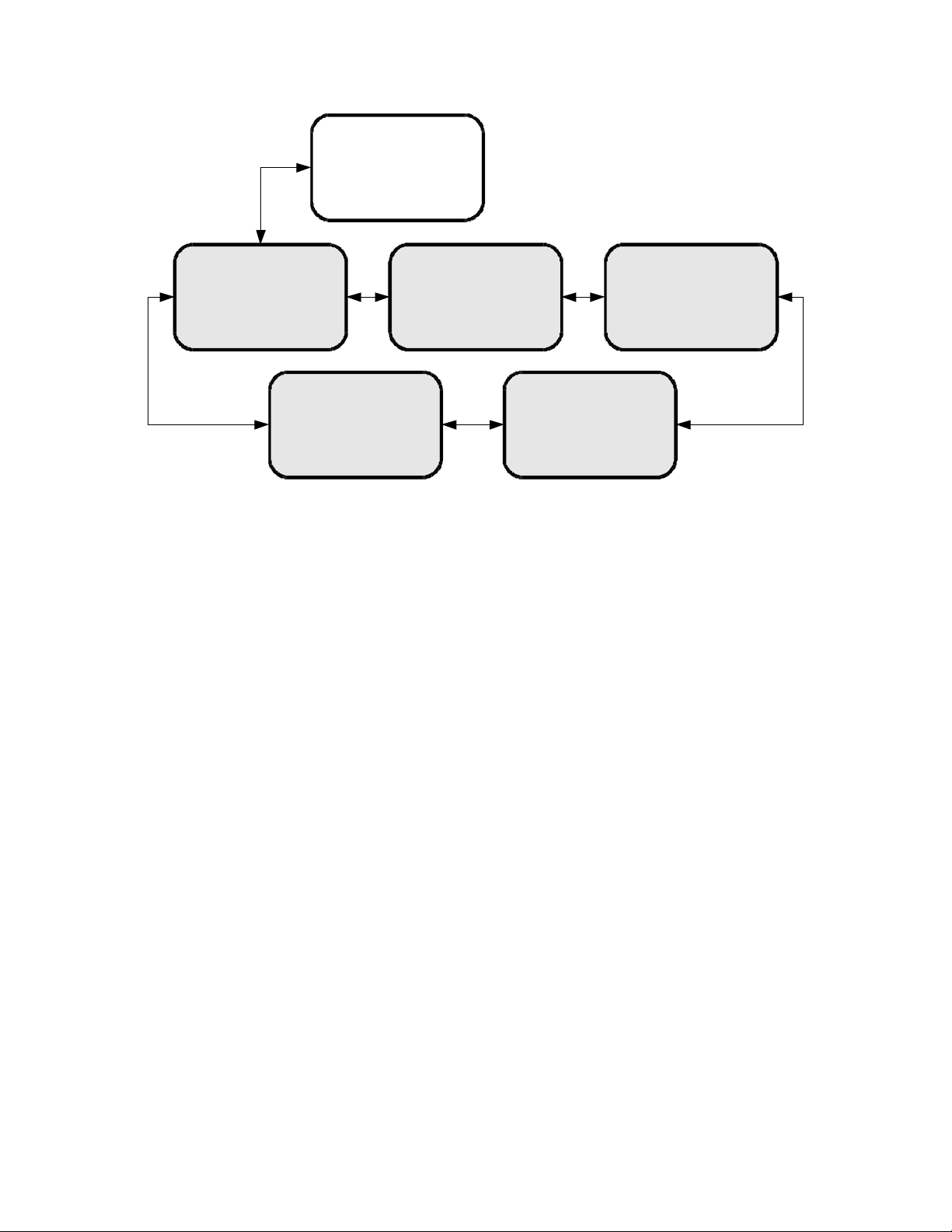
From the Status menu, the user can navigate through five sub-menus, each of them offers
various status-related information. From any of these sub-menus pressing the button
will being you back to the main menu options. The different sub-menus available in
Status are:
• Active Faults: describes any active faults that may be affecting the receiver.
•
Fault History: offers a list of past faults which may have occurred. Pushing 3 will
clear the fault history.
• Environment: indicates whether the internal fans are functioning inside the unit, and
the internal temperature of the receiver unit.
• Power Status: readings on the various voltage levels inside the receiver.
• Storage Status: gives an indication of the internal hard drive usage in the receiver.
14
X-Digital Systems
XDS-PRO4
R830001-1060 Rev B
Page 15
U/D
XDS PRO4
Status
Active Faults
OK
Storage Status
Total: 3884MB
Avail: 3683 MB
Used: 4%
L/R
Fault History
5: Tuner not Locked
CLR
Power Status
L/R
1.2V=1.21
5.0V=5.09
...
L/R
Environment
Temp: 39°C
Fan: HIGH
L/RL/R
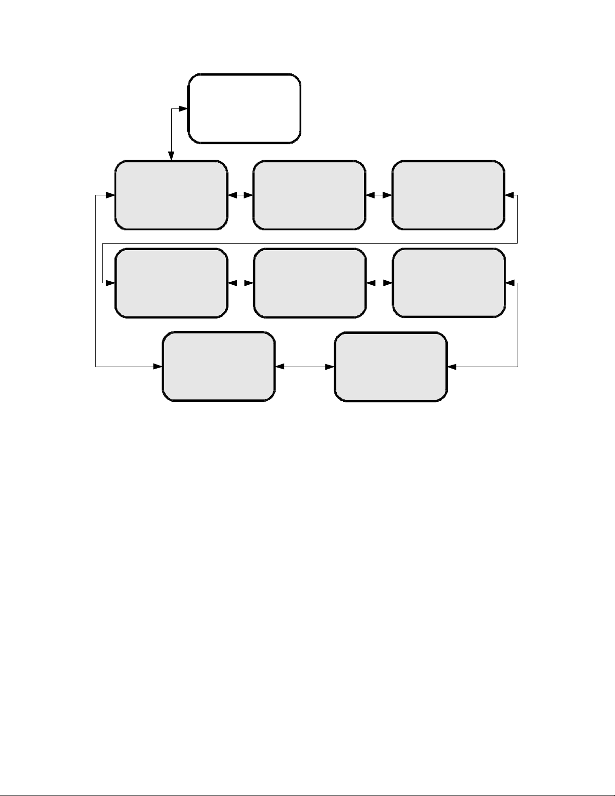
4.2.2 The SETUP Sub-Menus
By navigating from the Main Menu to Setup, the user reaches the Setup sub-menus. The
different sub-menus available under Setup are:
•
Serial Number: displays the receiver’s serial number. Pressing the 3 quick key
underneath “PWD” will display your receiver’s affiliate site password.
• M&C Ports: displays M&C port settings.
• Network: pressing the will navigate into the Network sub-menus.
• Alarms: allows you to set the alarm mask as a hex value.
•
Version: pressing SET in this menu will display the receiver’s firmware version.
•
Factory Defaults: pressing SET will offer you the option of resetting the receiver’s
settings to factory defaults. Press 1 to confirm or 3 to cancel. Reboot is required.
• Relays: allows you to switch any of the individual relay signals on Relay A or B to
on. Press to choose which Relay port to edit, then press SET to modify which
pins on the relay are activated. A ‘0’ is an un-activated relay and a ‘1’ is an activated
relay. The first position is the Relay 1, the second position is Relay 2, and so on.
• Tuner: pressing the will navigate into the Tuner sub-menus.
15
X-Digital Systems
XDS-PRO4
R830001-1060 Rev B
Page 16
U/D
XDS PRO4
Setup
Setup
Serial Number
XDSP-00000000
PWD
Setup
L/R L/R
M&C Ports
115K,8,None,1
Setup
Network
L/R
Setup
Factory Defaults
L/R
L/R
Setup
Alarms
0FFBDFFF
Setup
Tuner
L/R
Setup
Version
L/R
L/R
Setup
Relays
4.2.2.1 The SETUP:NETWORK Sub-Menus
Starting from the Main Menu and navigating to Setup option and pressing , and then
navigating to Network option and pressing SET, a user will have access to the Network
sub-menus. In these sub-menus, the receiver’s network settings can be made. The
network menu options include:
• DHCP (on or off): allows the user to specify a dynamic or static IP (on or off
respectively).
• LAN IP Address: in the case of a static IP, this allows the user to specify the LAN
IP address of the receiver.
• LAN Subnet Mask: allows the user to specify the LAN Subnet mask.
• WAN Address: specify the WAN IP address.
• WAN Subnet Mask: specify the WAN subnet mask.
• Gateway: allows the user to specify the default gateway to direct traffic to.
•
Test: when SET is pressed, this menu offers the user two test options. Pressing 1
allows you to ping the internet to ensure the network connection is functioning,
and pressing 2 tests the receiver’s website to ensure it is functioning. Pressing 3
exits from the Test menu.
16
X-Digital Systems
XDS-PRO4
R830001-1060 Rev B
Page 17
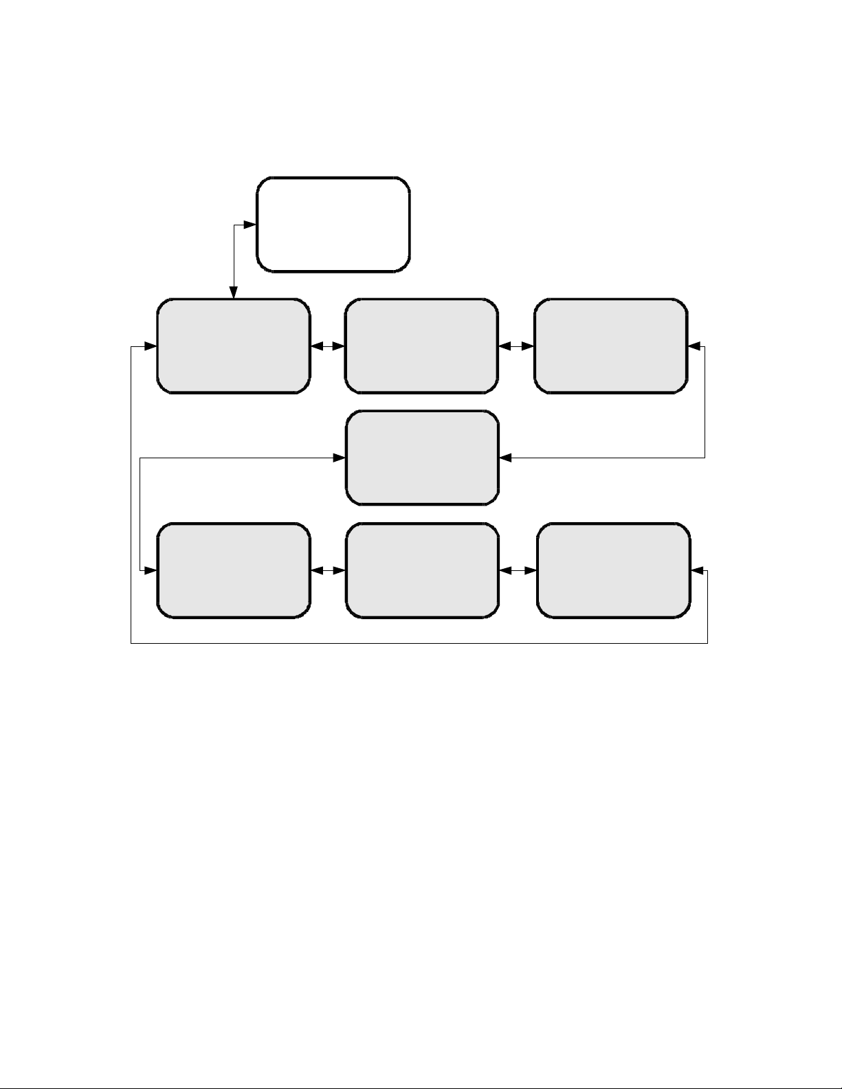
To modify any of these numeric values: use or to select which part of the IP to
change. Make a digit larger using , and to make a digit smaller using . Press SET
whenever you are done editing and want to commit a setting.
Setup
Network
U/D
Setup Network
DHCP
L/R L/R
Setup Network
L/R L/R
LAN Address
Setup Network
Setup Network
LAN Subnet
WAN Address
Setup Network
WAN Subnet
Setup Network
L/R L/R
Gateway
Setup Network
Test NOC
L/R
4.2.2.2 The SETUP:TUNER Sub-Menus
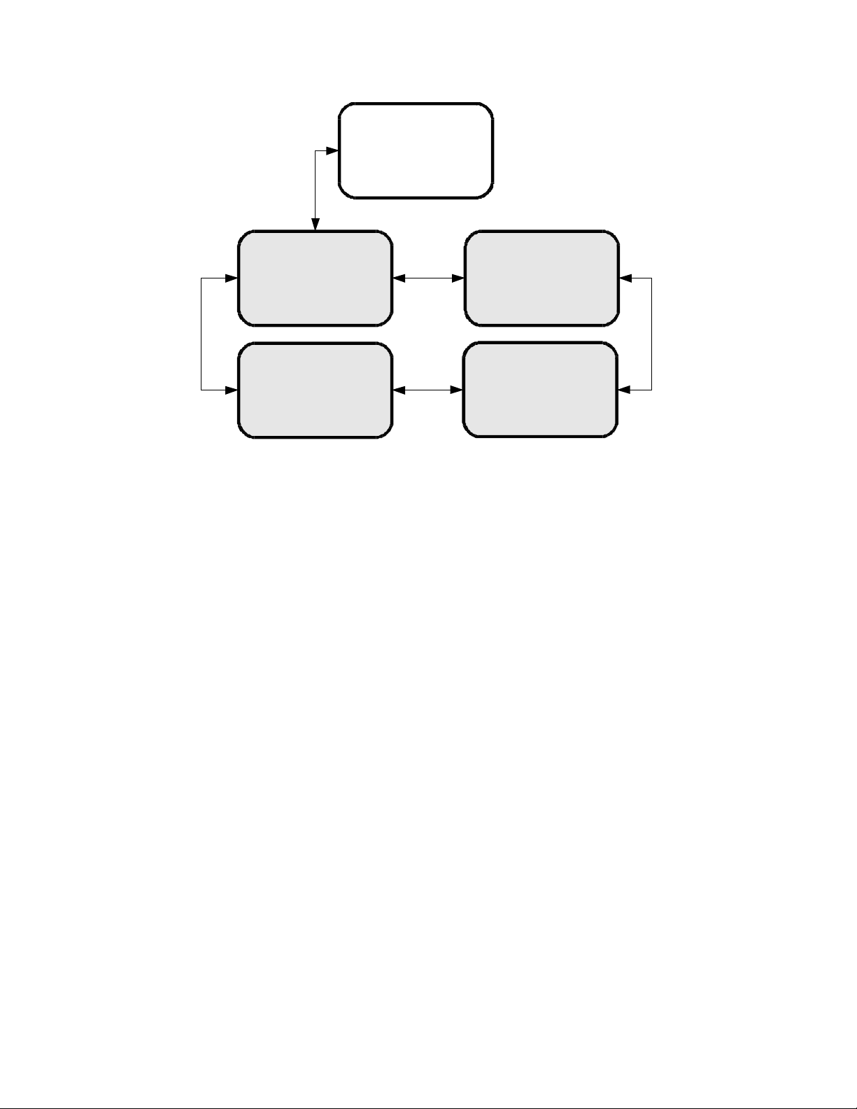
Starting from the Main Menu and navigating to Setup option and pressing , and then
navigating to Tuner option and pressing SET, a user will have access to Tuner submenus. From this level the user can change various attributes of the receiver’s tuner such
as frequency, symbol rate, LNB frequency, LNB Power(on or off), and view the FEC
setting. To change these options, the user navigates to the appropriate menu and presses
SET, then uses the arrows to choose the new setting, and press SET again to commit.
17
X-Digital Systems
XDS-PRO4
R830001-1060 Rev B
Page 18
U/D
Setup
Tuner
L/R
Setup
Frequency
Setup
LNB Power
L/R
L/R
Setup
Symbol Rate
L/R
Setup
FEC
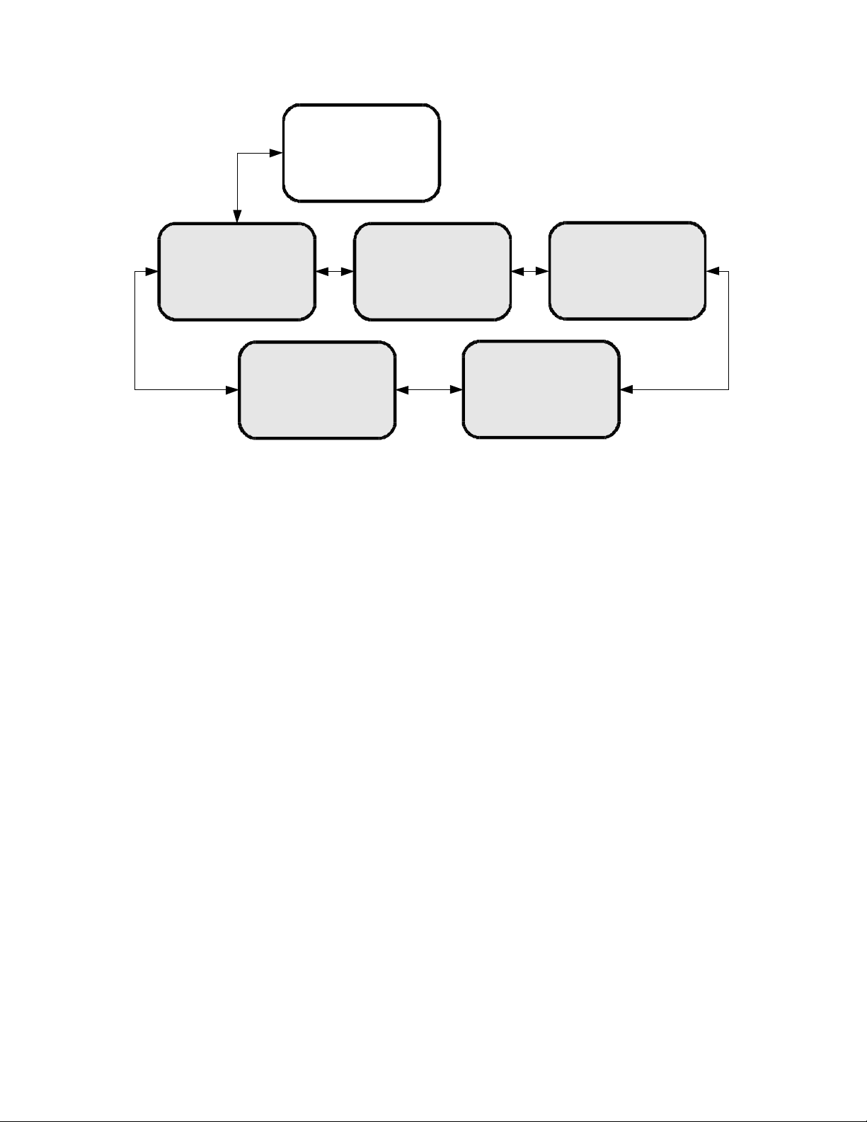
4.2.3 The AUDIO PORTS Sub-Menus
From the Audio Ports sub-menus, users can change the settings for each of the four ports
as well as headphones port. To choose which of these five ports to modify scroll between
them using or until the desired port is selected. Once the desired port is selected,
pressing 1 will take you to the Station sub-menu where call letters for a station may be
selected. Pressing 2 will take you to Programs sub-menu where a specific program may
be chosen from a list using and . Pressing 3 will navigate to the Spots sub-menu
where specific radio spots may be chosen from a list, again using and .
18
X-Digital Systems
XDS-PRO4
R830001-1060 Rev B
Page 19
U/D
XDS PRO4
Audio Ports
Audio Port A Audio Port B Audio Port C
L/R
Headphones
L/R
L/R
Audio Port D
L/RL/R
4.2.3.1 The AUDIO PORTS:SETUP Sub-Menus
Each of the five audio ports (Audio Port A-D, and Headphones) have their own identical
setup sub menus. From these menus, users may modify the station call number, the
current program played on the audio port, the current commercial spot played on the
audio port, and a couple miscellaneous audio settings (stereo or mono). These settings
may only be changed if a red-cross symbol is not visible on the port’s menu screen. If this
symbol does appear, it means that this audio port is controlled automatically by the
broadcaster, and that the user is unable to change any of these settings.
When the Station menu is selected by pressing SET, the receiver navigates to a screen
where call letters can be selected in order by using and to choose a letter for the
selected spot, and to choose which position in the name is selected for editing, and
SET to commit the changes to the station’s call letters. When Program or Spot menus are
selected, the receiver will display a list of programs or spots respectively. Use , and
to scroll through these lists, and use SET to select something from one of these lists.
When the Settings menu is selected, the user can change the audio ports output mode
from mono to stereo or vise versa. Again use the arrow keys and SET to accomplish this.
19
X-Digital Systems
XDS-PRO4
R830001-1060 Rev B
Page 20
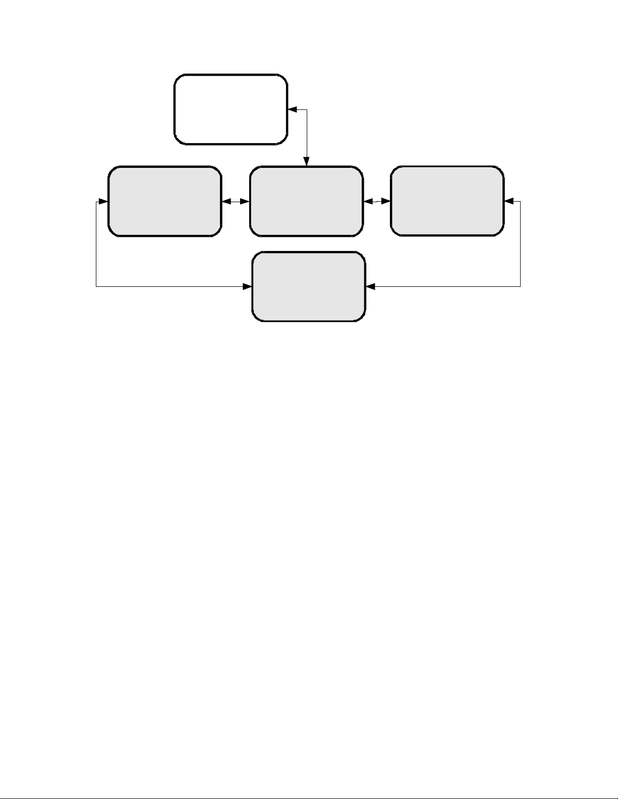
Audio Port #
U/D
Audio Port #
Station
L/R
Audio Port #
Program
Audio Port #
Settings
L/R
Audio Port #
Spot
L/RL/R
20
X-Digital Systems
XDS-PRO4
R830001-1060 Rev B
Page 21

5 ETHERNET SETUP
The XDS PRO4 Satellite Receiver is specifically designed to receive audio broadcasts via
satellite transmissions. It is also equipped with an “internet” only mode in which is can
receive audio data and receiver updates via its Ethernet port. For this feature to be
functional, the receiver must be connected to a network router or directly connected to an
internet connection. This portion of the User’s Guide will offer instruction on setting up
your receiver’s connection to the internet. For all of the below settings, please contact
your local network administrator for proper values.
5.1
Connecting the Cables
The Ethernet port on the back of the receiver accepts non-crossover RJ-45 cables.
Depending on your stations internet connection, you will either connect a RJ-45 cable
directly from a Cable or DSL modem box to the PRO4 receiver, or you will connect the
cable from a network router to the receiver. In either case, ensure that the cable is
squarely connected and that it clicks in when you connect it, so that it can not be removed
without pressing the plastic release button on the end of the cable. Ensure that your
internet connection is functioning before proceeding to the next steps.
5.2
Using DHCP or Static IP Addresses
Dynamic Host Configuration Protocol, or DHCP, allows the network administrator to
control the assignment of device IP assignment. If DHCP is on, the receiver will be
assigned an IP address automatically by the network. The implications of this are that the
IP of the receiver may change on a boot-up to boot-up basis. Turning DHCP will ensure
that a static, or non-changing, IP is assigned to the receiver as opposed to a dynamic one
determined at each startup of the receiver. For direction on turning DHCP on or off, refer
to section 4.2.2.1.
5.3
Assigning a TCP/IP Address
The TCP/IP address of the receiver serves as it identification number for the network.
Once the receiver is set up properly on a network, it will host a website which can be
loaded by typing is IP address into any standard web browser. Therefore the ability to
specify a static IP address for the receiver may be useful. To view and modify the IP
address, refer to section 4.2.2.1.
21
X-Digital Systems
XDS-PRO4
R830001-1060 Rev B
Page 22

5.4
Assigning a Subnet Mask
The subnet mask is used to determine where the network number in an IP address ends
and the node number in an IP address begins. A node is any device on a network that
needs a unique IP address to communicate (computer, server, router, PRO4 Receiver,
etc.). To set this value for your purposes, refer to section 4.2.2.1.
5.5
Assigning a Default Gateway
A gateway refers to a router or host which grants access to the internet. If you have not
enabled DHCP, you must specify the TCP/IP address of this default gateway. To set this
value, refer to section 4.2.2.1.
5.6
Proxy Server Configuration
If you wish to specify a proxy server for your receiver to route through, this must be done
using the receiver’s command prompt interface. To set this interface up, refer to section
8.1. To modify the proxy server, refer to the E0/E1 PROXY commands in section 8.2.
5.7
DNS Server Configuration
The DNS Server settings must be configured using the command interface. Instructions
for setting this interface up are in section 8.1. A receiver may specify up to three DNS
addresses using the E0/E1 DNS commands described in section 8.2.
22
X-Digital Systems
XDS-PRO4
R830001-1060 Rev B
Page 23

6 RECEIVER WEB INTERFACE
The XDS PRO4 receiver includes an on-board web interface that will publish itself on
your local area network once you have followed the steps in Chapter 5. From this web
interface you can view most of the receiver’s internal settings as well as the contents of
the receiver’s hard drive. To access this site, simply open a web browser connected to
your network and navigate to http://10.0.0.1 (unless you have manually changed your
LAN address to a different value, in which use this new value as the address). When the
page loads, you will see a login page. Once you have logged in, you will see three buttons
on the left labeled: General, Programming, and Content. After logging in, you are
viewing the information underneath the General button by default. Each of these buttons
offers a different set of options which are represented as tabs at the top of the screen.
6.1
The General Menu
The General menu lists most of the basic receiver attributes and settings. After logging in,
you start in the General menu by default. The tabs listed across the top for the General
menu are: Status, Tuner, Setup, and Relays. The Status tab is the tab displayed by default
upon entering the General menu. To navigate to another tab within a menu, simple click
the tab’s name.
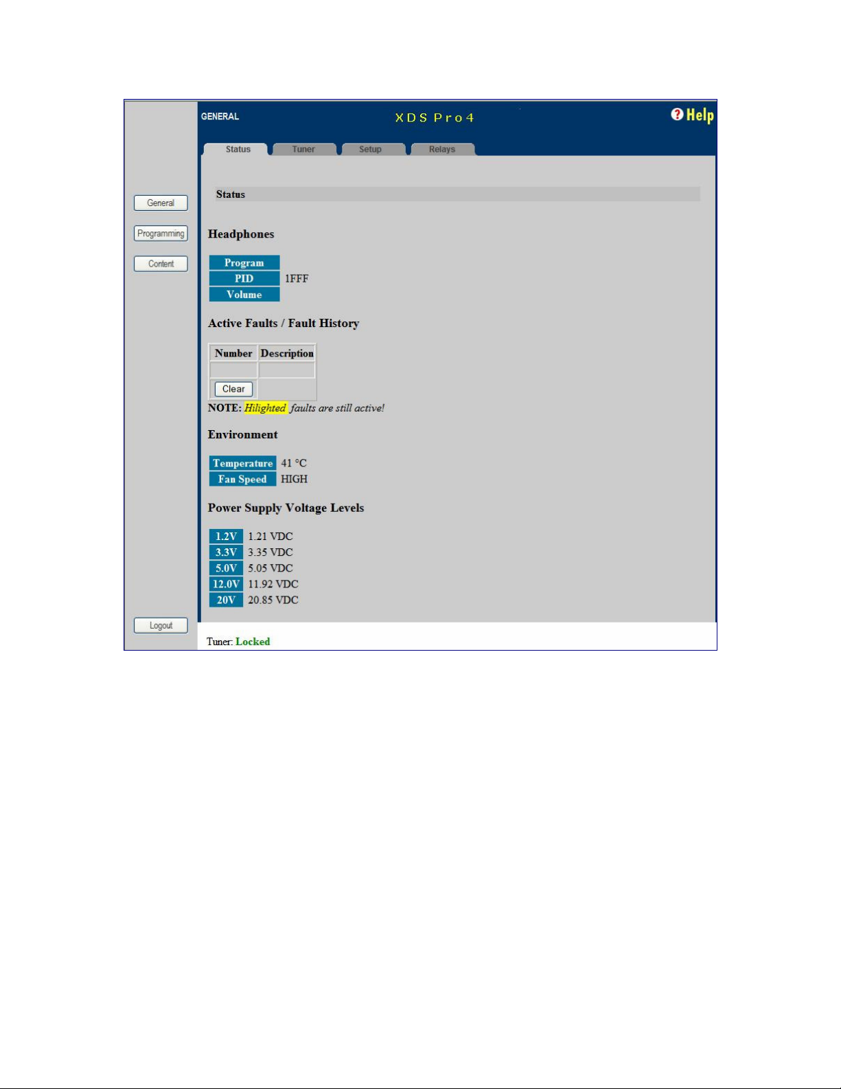
6.1.1 The Status Tab
The Status Tab displays basic attributes about its current output, its surroundings, errors,
and current power levels. On this tab you will see:
• A description of the Headphones output including Program, PID, and the volume.
• A list of current faults affecting the receiver, as well as a history of past faults
complete with a clear button to wipe the slate clean.
• A run-down of environmental factors including the receiver’s internal temperature
and fan speed, which is a measure of how hard the receiver is working to cool itself.
• A diagnostic of the power supply’s voltage levels. Ideally, the actual voltage matches
each of the named levels in each row.
Below is an actual image of the Status Tab. Your broadcaster’s logo may appear in the
top left corner. Notice the tabs along the top (and that the Status tab is the one currently
selected). Also notice the buttons on the side of the page, which will take you to a
different set of tabs if clicked.
23
X-Digital Systems
XDS-PRO4
R830001-1060 Rev B
Page 24
6.1.2 The Tuner Tab
The Tuner Tab presents the user with tuner related data. This data include:
• The frequency the tuner is tuned to.
• The tuner’s symbol rate.
• The locked or unlocked status of the tuner.
• The acquisition state of the tuner: acquiring, tracking, or fade.
• Eb/No, or energy per bit relative to noise floor (see section 4.2).
• AGC, or automatic gain control (see section 4.2).
• Fade count of the tuner.
• The number of Reed-Solomon errors that the tuner has ecountered.
• The LNB offset the tuner is currently using.
• The on or off status off the LNB.
The fade count and Reed-Solomon errors can be reset by pressing the Clear Statistics
button.
24
X-Digital Systems
XDS-PRO4
R830001-1060 Rev B
Page 25
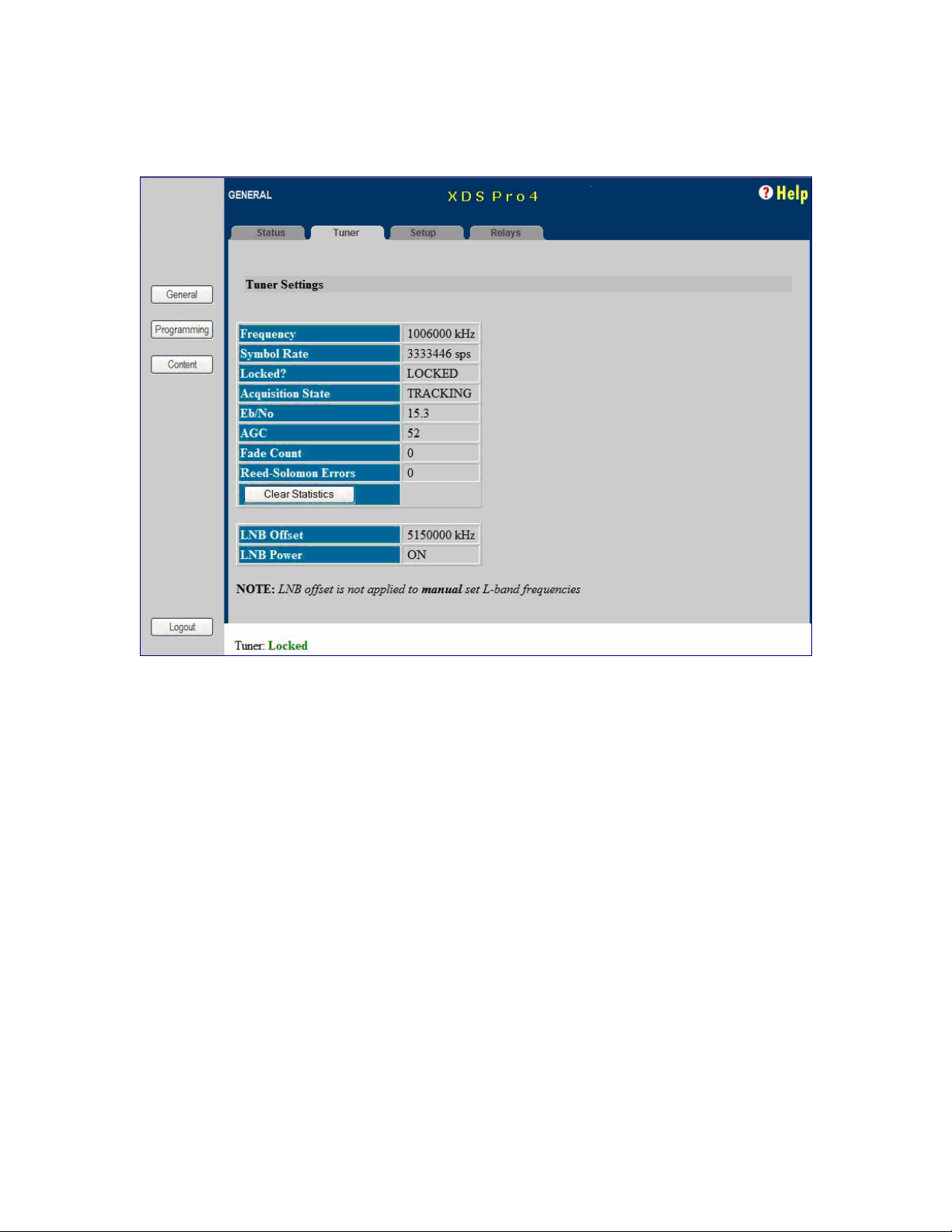
Below is an image of the tuner tab.
6.1.3 The Setup Tab
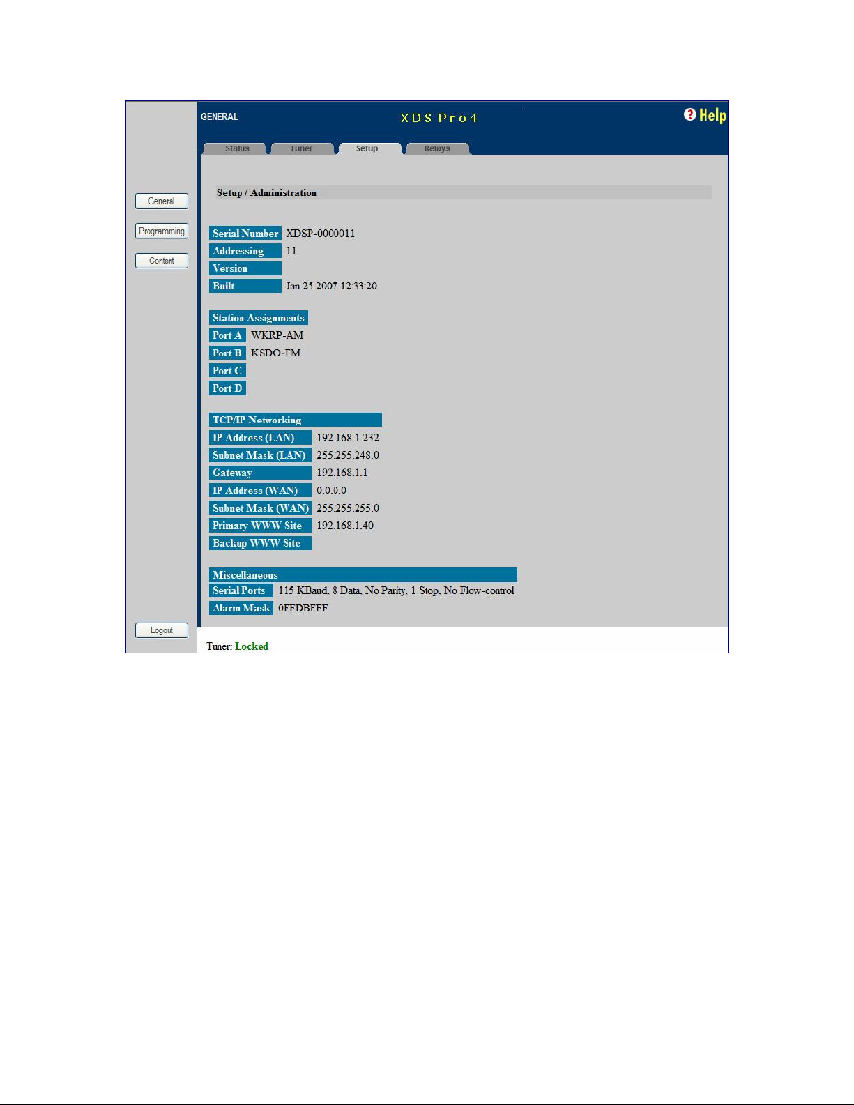
The Setup Tab shows even more detailed and specific receiver facts:
• The receiver’s serial number.
• The receiver’s addressing value.
• The receiver’s firmware version.
• The date that the current receiver’s firmware was designed.
• Station assignments for each of the four audio ports (i.e. station call numbers).
• Networking values used by the receiver including: LAN IP Address, LAN Subnet
Mask, Gateway, WAN IP Address, WAN Subnet Mask, primary NMS website URL,
and backup NMS website URL.
• Miscellaneous information including data about the serial ports and their settings,
and the current hexadecimal alarm mask.
An image of the Setup Tab follows.
25
X-Digital Systems
XDS-PRO4
R830001-1060 Rev B
Page 26
6.1.4 The Relays Tab
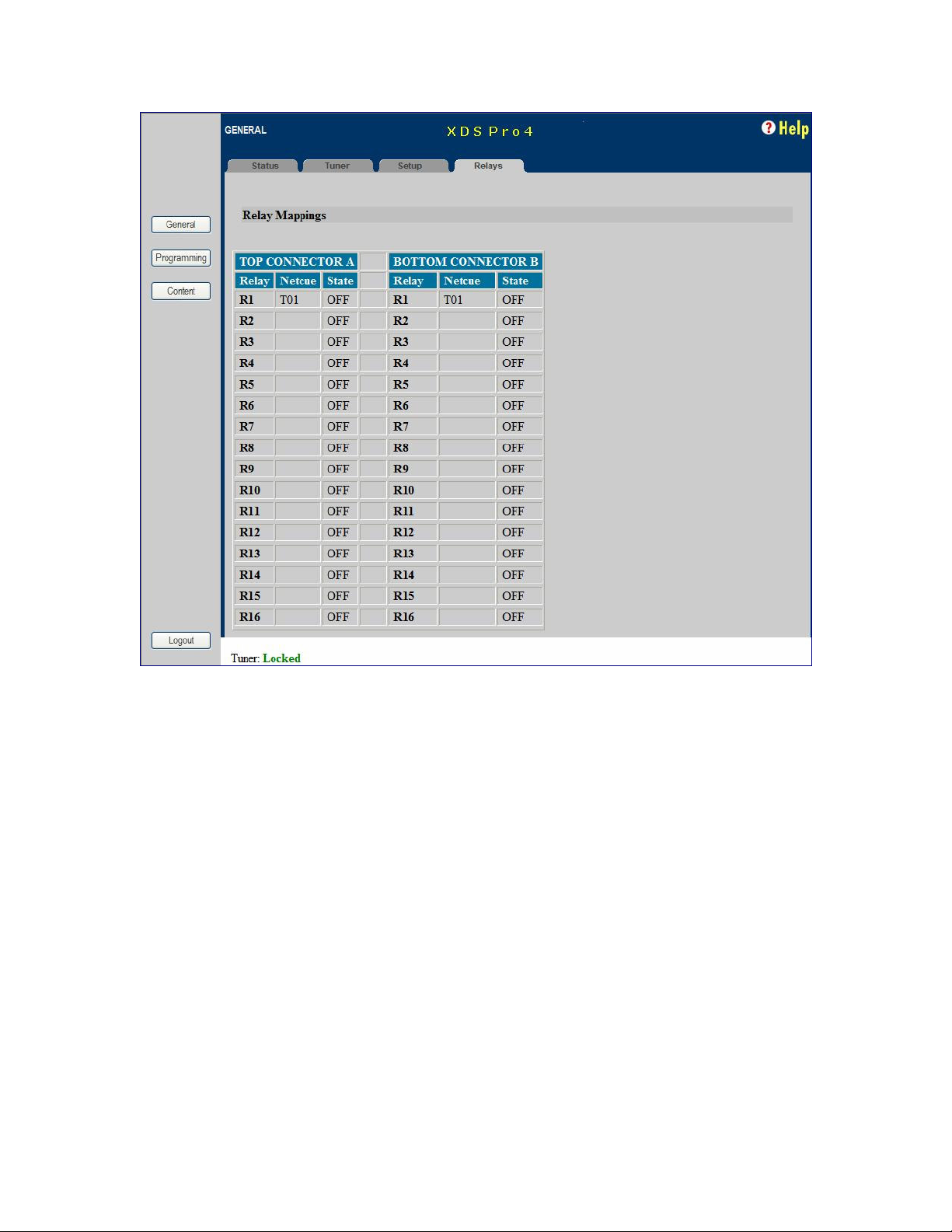
The Relays Tab lists all the 16 relay mappings complete with their net-cues and on/off
status for each of the two relay ports. Thus there are 32 total relays listed, 16 for each the
top and bottom relay ports.
Below is an image of the Relays Tab.
26
X-Digital Systems
XDS-PRO4
R830001-1060 Rev B
Page 27
6.2
The Programming Menu
From the Programming Menu, the user is able to view all of the programs and recordings
the receiver is equipped to receive and re-broadcast.
6.2.1 The Programs Tab
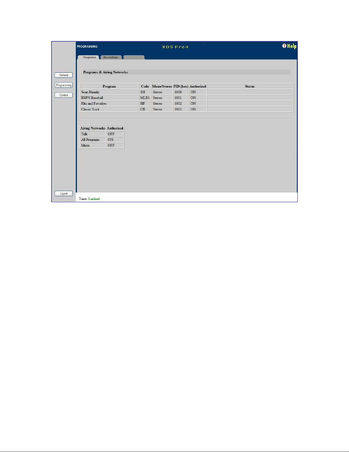
Each receiver is identified by the Network Management System as authorized to receive
and broadcast particular radio programs and as being part of certain airing networks.
From this tab, you can see which programs the receiver is set-up to receive and use. In
the Programs grid, you are given the Program Name, Code, Mono/Stereo Setting,
Program ID (PID), Authorization status, and Status for each Program on the receiver. In
the Airing Networks grid you see each Network the receiver may belong to and whether
it is currently authorized for this particular network.
Below is an image of the programs tab.
27
X-Digital Systems
XDS-PRO4
R830001-1060 Rev B
Page 28
6.2.2 The Recordings Tab
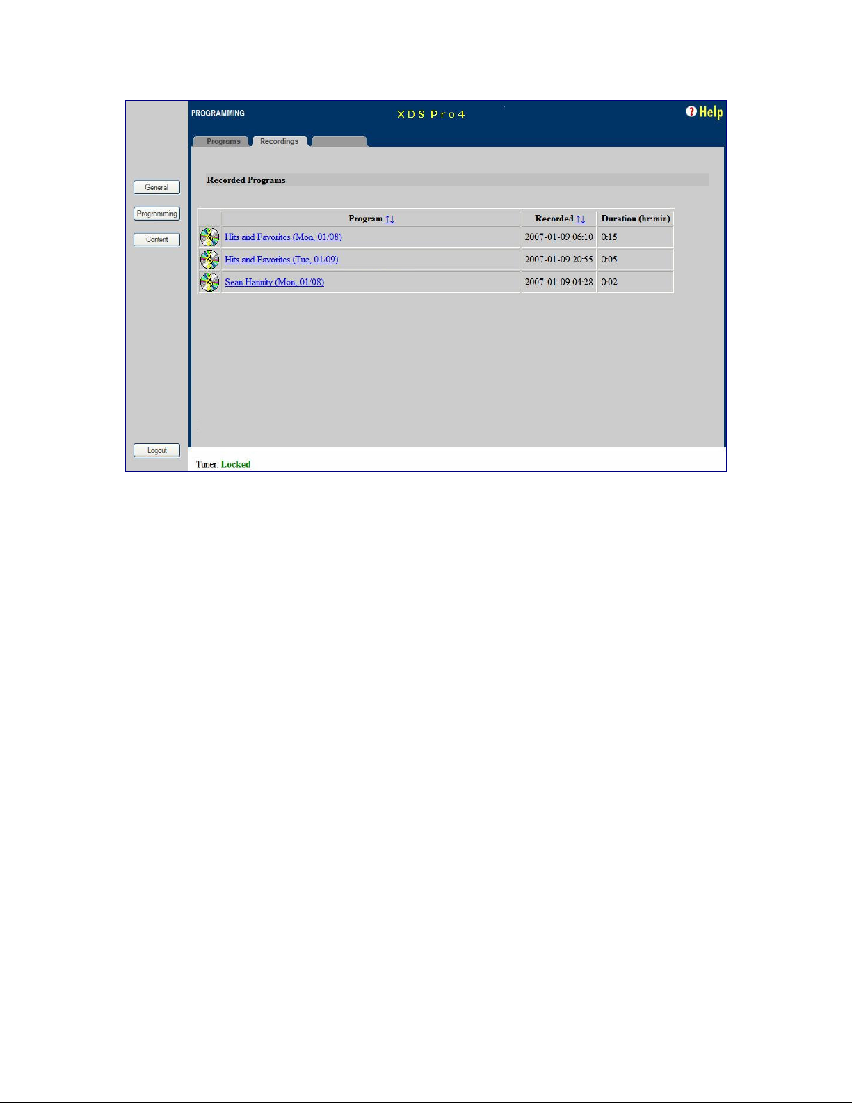
In the Recording Tab, every program which has been stored on the receiver’s internal
hard drive is listed. For each recording, you are given a link to download the recording to
your computer’s local hard drive, the date that it was recorded, and the length of the
recording.
28
X-Digital Systems
XDS-PRO4
R830001-1060 Rev B
Page 29
6.3
The Content Menu
The Content Menu lists all of the files which the receiver’s internal storage currently
holds.
6.3.1 The Audio Tab
The Audio Tab displays all audio type files which have been stored for later us by the
receiver. The file name (along with download link), ISCI code, received date, file
size/duration and buttons to delete(X) or play() are displayed for each file.
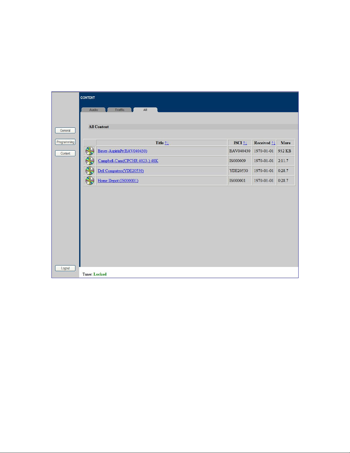
The audio, traffic and all tabs will all have the same layout. To see an example of what
these tabs will look like, view section 6.3.3, The All Tab.
6.3.2 The Traffic Tab
The Traffic Tab shows all traffic related text or document files. These files will most
likely include instruction from network managers, spot related information, or other readme files.
29
X-Digital Systems
XDS-PRO4
R830001-1060 Rev B
Page 30
6.3.3 The All Tab
The All Tab simply displays all files which the receiver is currently storing.
Here is what the Content tabs look like:
30
X-Digital Systems
XDS-PRO4
R830001-1060 Rev B
Page 31

7 AFFILIATE WEB INTERFACE
The XDS PRO4 Satellite Receiver is capable of communicating with and being
controlled by an external web application called the Network Management System. The
NMS is capable of many features which greatly simplify the management of a radio
station. Network managers can now automate much of the work that previously had to be
done manually on a station to station basis. Creation of a station schedule must be done
through the NMS. Additionally, a radio station user of the NMS may modify the relay
mappings on the receiver to specify which relays corresponds to which net-cue. The
following sections will instruct you on how to accomplish these tasks.
7.1
Accessing and Logging In
The website hosting your affiliate web page is provided by your broadcaster. Please refer
to the Quick Start Guide for instructions on navigating to this site.
After the page has loaded, type the username, which is your receiver’s serial number
(available on the back panel of your receiver and via the front panel display) and
password, which is given by navigating to the ‘XDS PRO4:Setup:Your Account’
submenu in the receiver’s front panel display (see section 4.2.2 for more details). Once
your correct username and password are typed in, press login.
7.2
Play Scheduling
The NMS is a powerful tool for managing your radio network. From the NMS, it is
possible to create a play schedule for your receiver. To create a station schedule follow
these steps:
• Log into the NMS (see section 7.1).
• On the navigation bar on the top of the page, click “Station Schedules”.
• Once the page loads, you should see a grid of the current station schedule for this
week. If your Affiliate login and password are authorized for multiple stations, there
will be a drop-down menu at the top of the page listing multiple stations, each with
different station schedules to edit. Select the station you wish to edit.
• Once you are viewing the station schedule which you wish to edit, ensure that you
are viewing the week you wish to edit. The week is listed in the upper right above
the schedule grid. If you wish to edit a different week use the arrow links to navigate
forwards or backwards in time.
• Once you are view the correct station schedule and the correct week, you are ready
to modify the schedule. Click the time on the left had side of the grid that you wish
to modify or add a program to.
31
X-Digital Systems
XDS-PRO4
R830001-1060 Rev B
Page 32
• If your station is authorized to play any programs, you will now see a drop-down list
of programs which you may add to this station schedule. Select the program and livefeed time that you wish to insert into this time slot and click “Next”.
• If you wish to play the program in its entirety, choose this option and click “Next”. If
you wish to play only part of the program select this option, and then define which
portion of the program you wish to insert by following the instruction. Click “Next”.
• This page allows you to tell the receiver what to do with the feed when it receives it.
Playing the program live will not require use of the receiver’s internal hard drive.
The other two options will store the program for later use. Click “Next” once you
have made your choice.
• On the next page, select the days of the week that you wish to play this program.
Only days which this program is broadcast will be available for selection. If this
program is to be recurring, do not select an end date. Click “Next”.
• Confirm that all of your settings for this program are correct and click “Finish”.
To delete or modify an already existing program on the schedule, click that program’s
name. There is a delete link in the bottom right. You may also click previous to change
any of the program’s settings.
7.3
Changing the Relay Mappings
There are 32 different relays on the PRO4 receiver, and each of these relays can
correspond to a different net-cue for a radio broadcast. You can use the NMS to specify
the relay mapping for the receiver. To do this
• Click Relay Mappings at the top of the page beneath the X-Digital Systems logo.
• Select the correct receiver from the receiver S/N drop-down list.
• Click the “Edit” button in the bottom right.
• Edit the text for the corresponding relay you wish to change.
• When done changing relays, press “Save”.
• To cancel the changes you have made and to go back to the previous relay mapping,
click “Cancel”.
Note!
Net-cues entered into the NMS’s relay-mappings text box bust be
upper-case alphanumeric, i.e. only upper-case letters, or
numbers.
7.4
Changing the Receiver’s Time Zone
Using the Affiliate website it is also possible to change the receiver’s time zone settings.
To do this, navigate to the Home page and select the appropriate time zone from the drop
32
X-Digital Systems
XDS-PRO4
R830001-1060 Rev B
Page 33

down list. If you would like to observe daylight savings time, indicate this using the
check box provided. To commit changes, click the update button.
33
X-Digital Systems
XDS-PRO4
R830001-1060 Rev B
Page 34

8 MONITOR AND CONTROL INTERFACE
The PRO4 Receiver is equipped with multiple methods for viewing and changing
receiver settings. The M&C Console Port on the back of the receiver can be used for this
purpose.
8.1
Setting up a Console Connection
To set up a console interface from your computer to the receiver:
• Connect a standard serial cable from the serial port on your computer to the port
labeled “Console” on the back of the receiver.
• Open HyperTerminal from the Start Menu: Start > All Programs > Accessories >
Communication > HyperTerminal.
• In the Connection Description dialog, enter “XDS PRO4 Console” as the connection
Name, and select a connection Logo. Press “OK”.
• In the Connect To dialog, select “COM1” in the Connect using drop down list.
Note!
If you have connected the serial cable to a different port rather
than COM1, select that port instead.
• In the COM1 Properties dialog, select 115200 in the “Bits per second” drop-down
list, 8 in the “Data bits” drop-down list, “None” in the “Parity” drop down list, 1 in
the “Stop bits” drop-down list, and Hardware in the “Flow control” drop down list.
Press “Apply” and then press “OK”.
You are now ready to communicate with the PRO4 Receiver via the console you have
created. There are a variety of typed commands that the receiver responds to. By default
the console is not logged into the receiver, and as such the console will have a very
limited set of commands to use. Without logging in, the user can only use status
commands and may not change any receiver settings. To log in, use one of these two
accounts:
• user/guest: the user account has a permission to change standard receiver settings
like program ID, monitoring settings, and volume settings.
• tech/ radio: the tech account has full access to every command the receiver has to
offer. Only use the account when trouble-shooting the receiver or performing
technical diagnostics.
To log into either of these use the LOGIN command, detailed below in section 8.2.
34
X-Digital Systems
XDS-PRO4
R830001-1060 Rev B
Page 35
8.2
Console Commands
Tasks are performed through the console via commands. The syntax for any command is
the name of the command, followed by a comma separated list of one or more option
command arguments. Below is a list of all commands available along what command
arguments are required and what the command does.
The ALARM Command: The ALARM command tells you, and allows you to change,
the current ALARM mask the receiver is using. To see the current ALARM mask
without modifying it, simple type ALARM without an argument following it. To change
the alarm mask, type: ALARM <MASK>, where <MASK> is a hexadecimal digit in the
range [0-FFFFFFFF]. Anything larger than FFFFFFFF will be interpreted as the largest
mask, FFFFFFFF. This command is only available to the tech profile.
The E0 and E1 Commands: The E0 and E1 commands change various settings for the
first and second Ethernet ports respectively. The command followed by any of the below
options will display that parameter if there is no argument given, or change that
parameter to the argument if an argument is given.
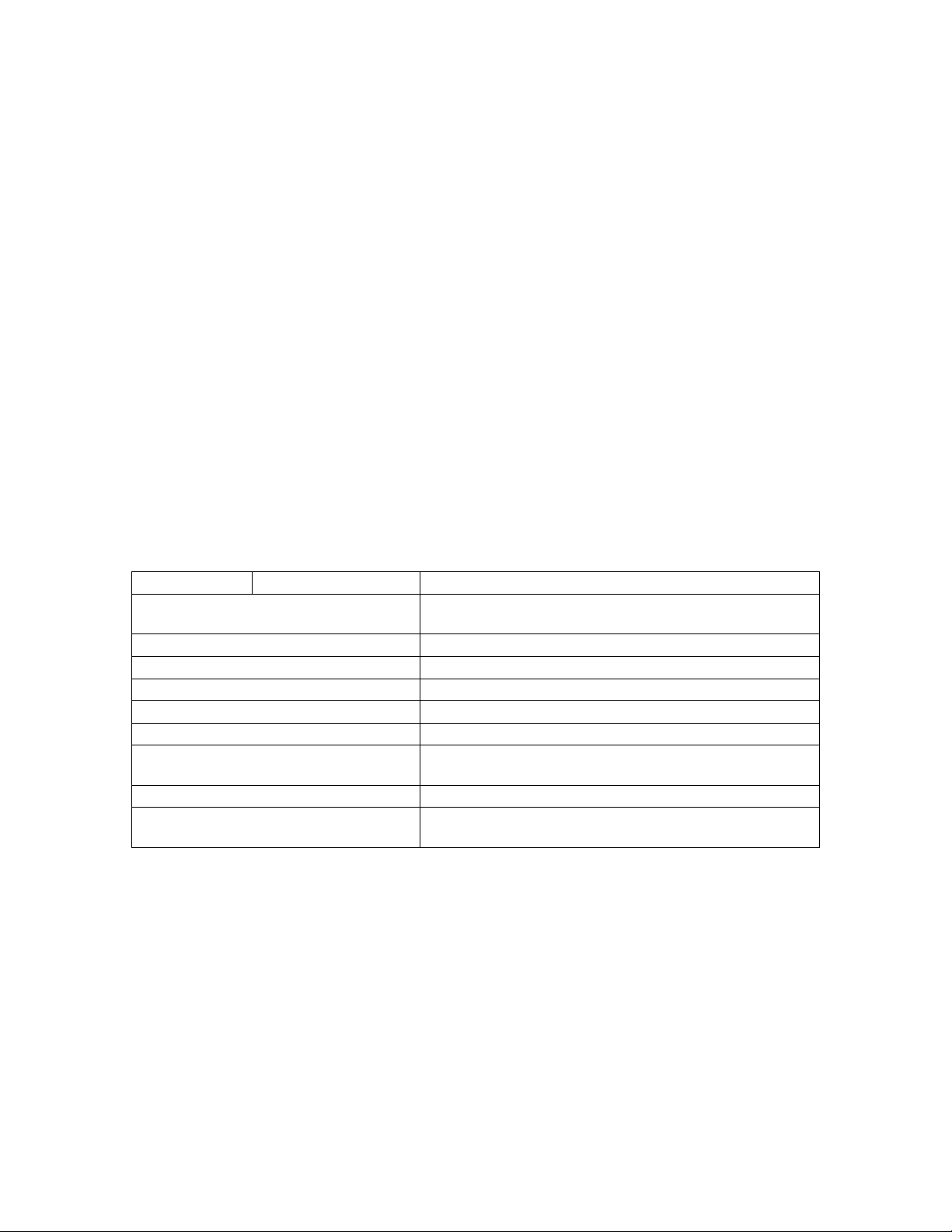
Option Argument Action
SHOW
MAC
DHCP ,[ON/OFF]
ADDR ,[a.b.c.d]
MASK ,[a.b.c.d]
PROXY ,[a.b.c.d]:PORT
DNS ,[a.b.c.d],…
GATEWAY ,[a.b.c.d]
WWW ,[a.b.c.d],[w,x,y,z]
Table 2. E0 or E1 Command Parameters
Shows various technical data regarding the specified
port.
Same as the SHOW option.
Sets DHCP to ON or OFF depending on the argument.
Sets the Ethernet port’s address to argument.
Sets the Ethernet port’s subnet mask to the argument.
Sets the Ethernet port’s proxy address and port.
Sets the Ethernet port’s DNS servers. One to three DNS
addresses can be specified in a coma delimited list.
Sets the Ethernet port’s gateway to the argument.
Sets the Ethernet’s primary URL to the first argument,
and sets the secondary URL to the second argument.
These commands are available to the tech and user profile.
The FACTORY Command: This command will reset all of the receiver’s settings to
factory defaults. The syntax is FACTORY DEFAULTS, [USER/FULL] where USER
will reset basic settings to factory defaults and FULL will additionally reset Ethernet and
Tuner parameters. Using this command will require a receiver restart.
This command is only available to the tech profile.
35
X-Digital Systems
XDS-PRO4
R830001-1060 Rev B
Page 36
The HELP Command: This command prints all of the commands available to the
current profile. There are no options for this command. This command is available to all
profiles.
The LOGS Command: This command deals with the receiver’s internal logs. There are
three possible options to be used with this command:
• SHOW: This option will display the receivers log file to the console screen.
• PURGE: This option will purge the receivers log and start over with a clean slate.
• MSG, ”message”: This option will place a message in the log file with whatever text
is enclosed in the quotes of the argument of this command. The argument is required.
This command is only available to the tech profile.
The LOGIN Command: This command will log the console into a user profile specified
by the parameters. The syntax is: LOGIN [username],[password]. The username and
password must match for the login to be successful. The two default argument
combinations for the user and tech profiles are “user,guest” and “tech,radio” respectively.
This command is available to all profiles.
The LOGOUT Command: This command will log the console out of whichever user
profile is currently logged in. Remember to LOGOUT each time you are done using the
console to change receiver settings.
Note!
Logins from previous console sessions stay active until another
LOGIN command over-rides the past one or the LOGOUT
command is used. For security, LOGOUT when you are done with
the console.
The PING Command: This command will attempt to ping the IP address specified by
the argument. The syntax is: PING [a.b.c.d] where [a.b.c.d] is the IP to ping. The IP is a
required argument. This command is a good way to test if your network connection is set
up correctly. This command is available to the user and tech profiles.
The QUIT Command: This command does the exact same thing as LOGOUT. There
are no options for this command and it is available to all profiles.
The SF Command: This command displays the fault history. See the SS command for a
table of what the fault codes mean. This command is available to all profiles.
The SN Command: This command displays the receiver’s serial number. It takes no
options. This command is available to all profiles.
The SS Command: This command displays the current status of the receiver in the form
a list of current faults which are affecting the receiver. There are no options for this
command. Below is a table which will help to interpret the binary code given by the
receiver:
36
X-Digital Systems
XDS-PRO4
R830001-1060 Rev B
Page 37
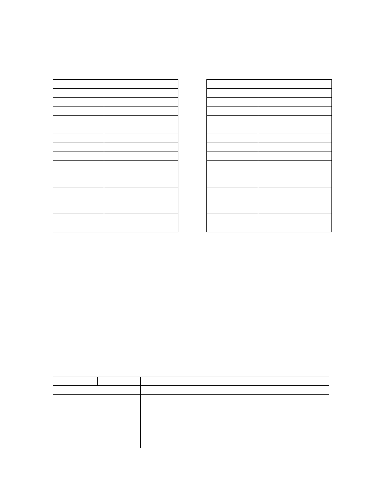
Error Value Error Name Error Value Error Name
0x00000001 FPGA Load Error 0x00010000 Recorder Overflow
0x00000002 DSP Load Error 0x00020000 Temp Warning
0x00000004 Ethernet Failure 0x00040000 Temp Critical
0x00000008 No Storage Device 0x00080000 reserved
0x00000010 Tuner Not Locked 0x00100000 reserved
0x00000020 reserved 0x00200000 reserved
0x00000040 reserved 0x00400000 reserved
0x00000080 reserved 0x00800000 LNB Over-current
0x00000100 reserved 0x01000000 reserved
0x00000200 reserved 0x02000000 reserved
0x00000400 reserved 0x04000000 reserved
0x00000800 reserved 0x08000000 URL Event Overflow
0x00001000 NV Config. Bad 0x10000000 Internet Down
0x00002000 reserved 0x20000000 Storage Full
0x00004000 DSP Timeout 0x40000000 SW Download Rdy
0x00008000 Fan Stopped 0x80000000 SW Download Err.
Table 3. SS and SF Error Code Values
This command is available to all profiles.
The TIME Command: This command deals with displaying and setting the internal
clock of the receiver. Simply typing TIME without any option will display the time
according to the receiver. Time is synchronized automatically with the satellite. Your
timezone may be set from the Affiliate webpage.
The TRACE Command: This command is used for diagnostic checks of the serial ports.
It is available only to the tech profile.
The TUNER Command: This command is used to view and modify all of the receiver’s
tuner settings. Typing this command without any options will display a useful usage
message. Type this command followed by one of these options/argument combinations to
view or modify tuner settings:
Option Argument Action
SHOW Shows various technical data regarding the specified port.
SET ,[kHz],[sps]
Sets the tuners radio frequency to [kHz] and the tuner’s
symbol rate to [sps].
LNB ,[kHz] Sets the tuner’s LNB offset to [kHz].
SR ,[sps] Sets the tuner’s symbol rate to [sps].
LNBV [ON/OFF] Sets LNBV to ON or OFF depending on argument.
CLEAR Clears all tuner statistics.
37
X-Digital Systems
XDS-PRO4
R830001-1060 Rev B
Page 38

Table 4. Tuner Command Parameters
The VER Command: This command, which takes no options, simply displays the
receiver’s firmware version to the console. This command is available to all profiles.
The VOL Command: This command sets the volume of the receiver’s headphone
output. The syntax is: VOL [v] where [v] is a value greater than or equal to 0 (mute) and
less than or equal to 63 (full volume). This command is available to the tech and user
profiles.
38
X-Digital Systems
XDS-PRO4
R830001-1060 Rev B
Page 39

9 SPECIFICATIONS
The following specifications are divided into sections corresponding to the carious
functional blacks within the receiver.
9.1
Receiver Interface Specification
LCD image display capability, backlighting
Keypad full 8 key-pad, menu buttons, arrow keys, enter key
Status LEDs power, signal, update, and fault indications
Monitor and Control Interface RS-232C compatible, DB-9 female
Web Interface automatically broadcast via LAN and WAN
Table 5. Interface Specifications
9.2
Mechanical/Electrical Specification
Dimensions 3.5” x 18” x 12”
Mounting 19”, 2RU
Weight 8 lbs
Input Voltage 90 – 240 VAC (50/60 Hz)
Power Consumption 65 W maximum
Table 6. Mechanical and Electrical Specifications
9.3
Environmental Specifications
The power supply will be a 65W universal input switching power supply that is UL
safety rated. We expect the system to operate without a need for a fan in air conditioned
locations. The fan will be electronically controlled via temperature sensor. This will
allow the unit to operate under less than optimal conditions.
39
X-Digital Systems
XDS-PRO4
R830001-1060 Rev B
Page 40
9.4
M&C Interface Connector Pin-Outs
The Monitor and Control (M&C) port allows basic configuration of the XDS receiver via
an asynchronous RS232C electrical interface. It uses the following protocol settings:
115.2K baud, 8 data bits, No Parity, 1 stop bits, and no hardware flow control. In addition
to the asynchronous interface, the M&C connector provides a status relay output and four
optical inputs. The four optical inputs are activated grounding the input signal. The
following table provides the pin-out for the M&C port.
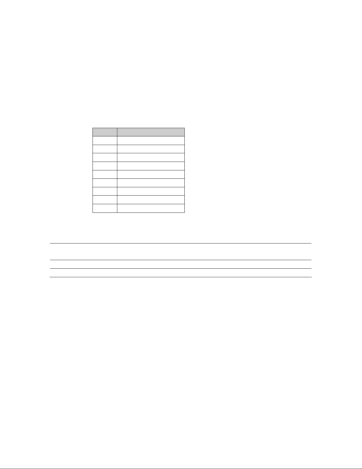
PIN FUNCTION
1 Ground
2 TX
3 RX
4 ALARM
5 Ground
6 OPTO1
7 OPTO2
8 OPTO3
9 OPTO4
Table 7. M&C Port Pin-Out
Connection
DB-9F
Asynchronous Port 115.2K baud, 8 data bits, no parity, no hardware
flow control
Relay Format 1 Form A
Optical Inputs 4 Input Signals, Connect to ground to activate
Table 8. M&C Port
40
X-Digital Systems
XDS-PRO4
R830001-1060 Rev B
Page 41
9.5
Relay Outputs
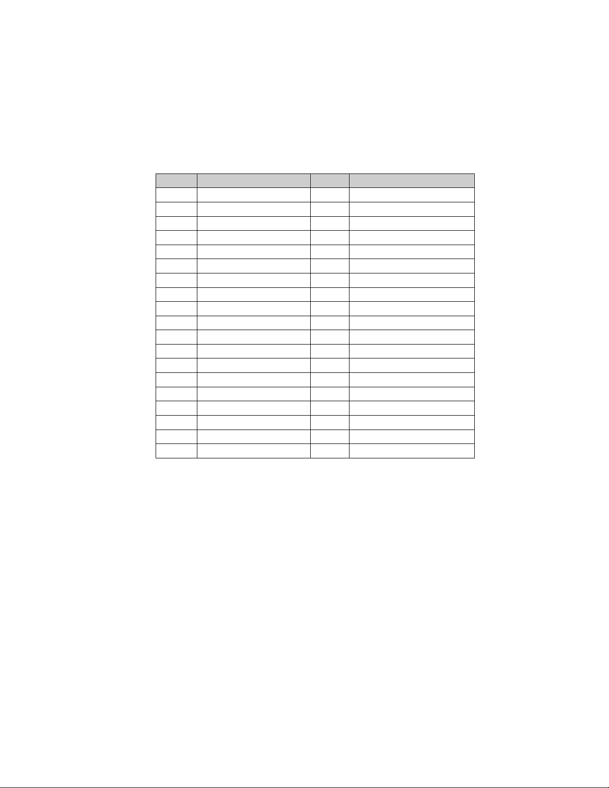
There are two DB-37 connectors on the rear panel which together contain a total of 32
mappable relay (or contact) closures. The following tables provide the pin-outs for the
two relay connectors.
PIN FUNCTION PIN FUNCTION
1 RLY1A 20 RLY1B
2 RLY2A 21 RLY2B
3 RLY3A 22 RLY3B
4 RLY4A 23 RLY4B
5 Ground 24 Ground
6 RLY5A 25 RLY5B
7 RLY6A 26 RLY6B
8 RLY7A 27 RLY7B
9 RLY8A 28 RLY8B
10 Ground 29 RLY9B
11 RLY9A 30 RLY10B
12 RLY10A 31 RLY11B
13 RLY11A 32 RLY12B
14 RLY12A 33 Ground
15 NQ TxData 34 RLY13B
16 RLY13A 35 RLY14B
17 RLY14A 36 RLY15B
18 RLY15A 37 RLY16B
19 RLY16A
Table 9. Relay Port A Pin-Out
41
X-Digital Systems
XDS-PRO4
R830001-1060 Rev B
Page 42
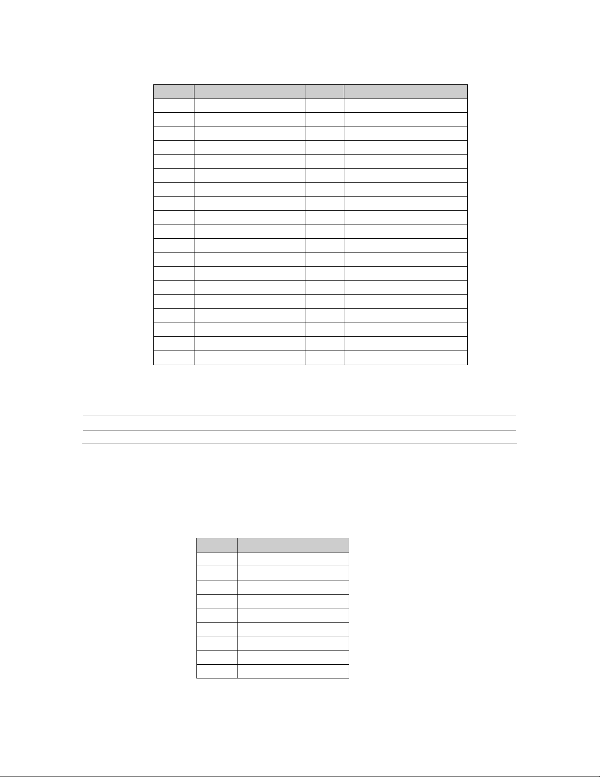
PIN FUNCTION PIN FUNCTION
1 RLY1A 20 RLY1B
2 RLY2A 21 RLY2B
3 RLY3A 22 RLY3B
4 RLY4A 23 RLY4B
5 Ground 24 Ground
6 RLY5A 25 RLY5B
7 RLY6A 26 RLY6B
8 RLY7A 27 RLY7B
9 RLY8A 28 RLY8B
10 Ground 29 RLY9B
11 RLY9A 30 RLY10B
12 RLY10A 31 RLY11B
13 RLY11A 32 RLY12B
14 RLY12A 33 Ground
15 Ground 34 RLY13B
16 RLY13A 35 RLY14B
17 RLY14A 36 RLY15B
18 RLY15A 37 RLY16B
19 RLY16A
Table 10. Relay Port B Pin-Out
Connection DB-37M
Contacts 16 Relays
Format Form A
Table 11. Relay Outputs
9.6
Analog Audio Output
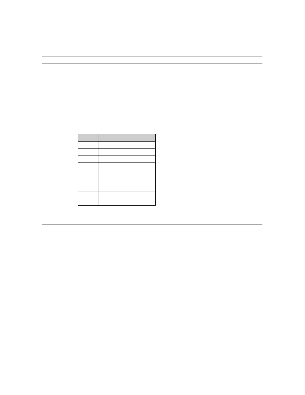
The receiver has four analog audio output ports. The following table has the pin-outs of
the analog output ports.
PIN FUNCTION
1 L OUT+
2 Ground
3 LOUT+
4 Ground
5 R OUT+
6 L OUT7 Ground
8 LOUT-
X-Digital Systems
XDS-PRO4
9 R OUT-
Table 12. Analog Audio Output Pin-out
42
R830001-1060 Rev B
Page 43
Connection DB-9M
Format Balanced Pair L, R
Range -10 to +4dBu nominal (+22 max)
Performance 0.1% THD 85dB dynamic range
Table 13. Analog Audio Output
9.7
Analog Audio Input
The receiver has one analog audio input port. The following table has the pin-out of the
analog input port.
PIN FUNCTION
1 L IN+
2 Ground
3 Not Connected
4 Ground
5 R IN+
6 L IN7 Ground
8 Not Connected
9 R IN-
Table 14. Analog Audio Input Pin-out
Connection DB-9M
Format Balanced Pair L, R
Range +4dBu nominal (+22max)
Table 15. Analog Audio Input
43
X-Digital Systems
XDS-PRO4
R830001-1060 Rev B
Page 44
9.8
Digital Audio Output
The receiver has a single digital audio output port that provides AES/EBU versions of the
first two analog audio ports (Ports A and B). The Port A audio is located on the pair of
CH0 signals while the Port B audio is located on the pair of CH1 signals. The following
table contains the pin-out of the digital audio port.
PIN FUNCTION
1 CH0_TX+
2 Ground
3 Not Connected
4 Ground
5 CH1_TX+
6 CH0_TX7 Not Connected
8 Not Connected
9 CH1_TX-
Table 16. Digital Audio Output Pin-out
Connection DB-9M
Format Balanced AES/EBU
Table 17. Digital Audio Output
44
X-Digital Systems
XDS-PRO4
R830001-1060 Rev B
Page 45
9.9
PAD/ASYNC Output Port
The PAD port (Program Associated Data) relays information which is carried along with
the audio data received. I.e. song and artist information, or relay queues to trigger events.
Below is a pin-out table for the PAD port.
PIN FUNCTION
1 P0_TX
2 P1_TX
3 P2_TX
4 P3_TX
5 Not Connected
6 Ground
7 Ground
8 Ground
9 Ground
Table 18. PAD/ASYNC Output Port Pin-out
Connection
DB-9F
Asynchronous Port variable up to 115.2K baud, 8 data bits, no parity, no
hardware flow control
Table 19. PAD/ASYNC Port
9.10
Ethernet Port
Connection RJ-45
Connection Rate 10/100Base-TX (Auto)
Number of Ports 3 external, 1 internal
Max Output IP Rate Up to 20 Mbps (combined for all ports)
VLAN Each port is managed for VLAN use
9.11
Modem (POTS) Port
Connection RJ-11
Connection Rate 14.4L, 28.8L, 56k
Format 8Bits, No parity, One Stop
45
X-Digital Systems
XDS-PRO4
R830001-1060 Rev B
Page 46

9.12
RF Input Parameters
Data will be demodulated and then de-multiplexed by PID (Program ID). On demand, the
de-multiplexed data will be transmitted via the Ethernet switch to any of the devices
requesting such data.
Connection 75 ohm F-type connector
Frequency Input Range 950 to 2150 MHz
Input Level -65dBm to -25dBm
Symbol rate 2 to 40 Msps
Modulation Scheme QPSK
Forward Error Correction modes Reed-Solomon and Viterbi (DVB-S)
LNB Power 20VDC 500mA MAX
46
X-Digital Systems
XDS-PRO4
R830001-1060 Rev B
 Loading...