

X-Digital System XDS PRO1 User Manual

XDS PRO1
Satellite Receiver
User’s Guide
Copyright © 2006 X-Digital Systems, Inc.
All rights reserved. No part of this document may be reproduced or transmitted in any form or by any means,
electronic or mechanical, including but not limited to photocopying, recording, or by any information storage and
retrieval system without the prior written permission from X-Digital Systems, Inc.
Warning and Disclaimer
This document is intended to provide information about installing and operating the “XDS-PRO1 DVB Satellite
Receiver”. Every effort has been made to make this document as complete and accurate as possible, but no warranty or
fitness is implied. The information is provided on an “as is” basis and X-Digital Systems shall have neither liability
nor responsibility to any person or entity with respect to any loss or damages arising from the information contained in
this document.
Acknowledge of Trademarks
Any product or corporate names used herein may be trademarks or registered trademarks, and are only used for
identification and explanation, without intent to infringe. Any terms mentioned or used that are known trademarks or
service marks have been appropriately capitalized and italicized. X-Digital Systems, Inc. cannot attest to the accuracy
of this information. Use of a term in this manual should not be regarded as affecting the validity of any trademark or
service mark.
Printed in the United States of America
X-Digital Systems, Inc.
6260 Sequence Drive
San Diego, CA 92121
Patent Pending
X-Digital Systems, Inc., DVB Satellite Receiver – Patents Pending
Approved external telecom power cross protection must be incorporated into
the final installation in accordance with Annex NAC of UL/CSA standard
Warning!
60950-1. Failure to comply may result in a fire or electric shock hazard and
will void regulatory compliance certification.
THIS DEVICE COMPLIES WITH PART 15 OF THE FCC RULES. OPERATION OF THIS DEVICE IS
SUBJECT TO THE FOLLOWING TWO CONDITIONS: (1) THIS DEVICE MAY NOT CAUSE
HARMFUL INTERFERENCE, AND (2) THIS DEVICE MUST ACCEPT ANY INTERFERENCE
RECEIVED, INCLUDING INTERFERENCE THAT MAY CAUSE UNDESIRED OPERATION.
XDS PRO1 Receiver User’s Guide
X-Digital Systems
Rev A - August 29, 2009
2

TABLE OF CONTENTS
1 INTRODUCTION ................................................................................................... 6
1.1 Important Information ...................................................................................... 6
1.2 Hardware Upgradeability ................................................................................. 6
1.3 Hardware Versatility ........................................................................................ 6
1.4 Network Management System.......................................................................... 7
2 GETTING STARTED ............................................................................................. 8
2.1 General Guidelines........................................................................................... 8
2.2 Unpacking the Receiver ................................................................................... 8
2.2.1 List of Contents ........................................................................................ 9
2.3 Safety Precautions ............................................................................................ 9
2.3.1 Excessive Temperature ............................................................................. 9
2.3.2 Proper Ventilation .................................................................................... 9
2.3.3 Heat, Humidity, and Dust ......................................................................... 9
2.3.4 Power Cord Cabling ............................................................................... 10
2.3.5 Proper Grounding ................................................................................... 10
2.3.6 Circuit Overloading ................................................................................ 10
2.3.7 Foreign Objects ...................................................................................... 10
2.4 Physical Installation of the Receiver............................................................... 11
2.4.1 Rack Mounting the Receiver .................................................................. 11
2.4.2 Uneven Loading of Rack ........................................................................ 11
2.5 Connecting to the Satellite Dish ..................................................................... 11
2.5.1 DC Voltage Requirement ....................................................................... 11
2.5.2 Warnings About Shorting DC ................................................................. 12
2.6 Connecting to the Ethernet Network............................................................... 12
2.6.1 Connecting the Cables ............................................................................ 12
2.6.2 Using DHCP or Static IP Addresses ....................................................... 12
2.6.3 Assigning a TCP/IP Address .................................................................. 13
2.6.4 Assigning a Subnet Mask ....................................................................... 13
2.6.5 Assigning a Default Gateway ................................................................. 13
2.6.6 Proxy Server Configuration .................................................................... 13
2.6.7 DNS Server Configuration ..................................................................... 13
2.7 Connecting the Audio Port ............................................................................. 13
2.7.1 Analog Audio Port ................................................................................. 14
2.8 Connecting the Relay Port .............................................................................. 14
2.8.1 Physical Ports ......................................................................................... 14
2.8.2 Cues ....................................................................................................... 14
2.9 Connecting the Program Associated Data (PAD) Port .................................... 14
2.9.1 In-Band Ancillary Data .......................................................................... 14
2.9.2 Out-of-Band Ancillary Data ................................................................... 15
3 Front Panel ............................................................................................................ 16
3.1 Status LEDs ................................................................................................... 16
3.1.1 The Power LED ..................................................................................... 16
3.1.2 The Signal LED ..................................................................................... 16
3.1.3 The Update LED .................................................................................... 16
3.1.4 The Fault LED ....................................................................................... 16
XDS PRO1 Receiver User’s Guide
X-Digital Systems
Rev A - August 29, 2009
3

4 MONITOR AND CONTROL INTERFACE.......................................................... 17
4.1 Setting up a Console Connection .................................................................... 17
4.2 Console Commands ....................................................................................... 19
4.2.1 The ALARM Command ......................................................................... 19
4.2.2 The E0 and E1 Commands ..................................................................... 19
4.2.3 The Factory Command ........................................................................... 20
4.2.4 The FAN Command ............................................................................... 20
4.2.5 The HELP Command ............................................................................. 20
4.2.6 The LOGS Command ............................................................................. 21
4.2.7 The Login Command.............................................................................. 21
4.2.8 The Logout Command ............................................................................ 21
4.2.9 The PASS command .............................................................................. 21
4.2.10 The PID command ................................................................................. 21
4.2.11 The PORT Command ............................................................................. 22
4.2.12 The PING Command .............................................................................. 22
4.2.13 The QUIT Command.............................................................................. 22
4.2.14 The SF Command .................................................................................. 22
4.2.15 The SN Command .................................................................................. 22
4.2.16 The SS Command .................................................................................. 23
4.2.17 The TIME Command ............................................................................. 23
4.2.18 The TUNER Command .......................................................................... 23
4.2.19 The VER Command ............................................................................... 24
5 XPING (X-Digital Receiver Discovery Tool) ........................................................ 25
5.1 Usage ............................................................................................................. 25
6 RECEIVER WEB INTERFACE ............................................................................ 26
6.1 The General Menu ......................................................................................... 26
6.1.1 The Status Tab ....................................................................................... 26
6.1.2 The Tuner Tab........................................................................................ 27
6.1.3 The Setup Tab ........................................................................................ 29
6.1.4 The Relays Tab ...................................................................................... 31
6.1.5 The Opto Inputs Tab .............................................................................. 31
6.1.6 The Logs Tab ......................................................................................... 32
6.2 The Programming Menu ................................................................................ 33
6.2.1 The Programs Tab .................................................................................. 33
6.2.2 The Recordings Tab ............................................................................... 34
6.3 The Content Menu ......................................................................................... 34
6.3.1 The Audio Tab ....................................................................................... 35
6.3.2 The Traffic Tab ...................................................................................... 35
6.3.3 The All Tab ............................................................................................ 35
7 AFFILIATE WEB INTERFACE ........................................................................... 36
7.1 Accessing and Logging In .............................................................................. 36
7.2 Play Scheduling ............................................................................................. 37
7.3 Changing the Relay Mappings ....................................................................... 44
7.4 Port Schedules ............................................................................................... 44
7.5 Configuration ................................................................................................. 45
8 SPECIFICATIONS ............................................................................................... 47
XDS PRO1 Receiver User’s Guide
X-Digital Systems
Rev A - August 29, 2009
4

8.1 Receiver Interface Specification ..................................................................... 47
8.2 Mechanical/Electrical Specification ............................................................... 47
8.3 Environmental Specifications ......................................................................... 47
8.4 8.4 M&C Interface Connector ........................................................................ 47
8.5 8.5 Relay Outputs .......................................................................................... 48
8.6 Analog Audio Output ..................................................................................... 49
8.7 Analog Audio Input ....................................................................................... 49
8.8 PAD/ASYNC Output Port ............................................................................. 50
8.9 Ethernet Port .................................................................................................. 50
8.10 RF Input Parameters ...................................................................................... 51
XDS PRO1 Receiver User’s Guide
X-Digital Systems
Rev A - August 29, 2009
5
1 INTRODUCTION
Welcome to the future of digital audio for the radio industry. This User’s Guide is your
handbook for the X-Digital PRO1 digital audio receiver. This receiver is equipped to
deliver audio services in high quality digital audio for your radio station. It has been
designed to make use of all the digital communication features available today, and to be
upgraded to take advantage of the technologies of tomorrow.
The purpose of this guide is to provide an in depth technical guide to the PRO1 receiver.
Please review the Quick Start Guide and Network Data sheet included with your receiver
for step by step instructions on setting up your receiver.
1.1 Important Information
Throughout this guide, you will find icons designed to help you quickly spot important
information:
The note icon identifies information for the proper
operation of your equipment, including helpful hints,
Note!
Caution!
Warning!
shortcuts, or important reminders
The caution icon identifies information that requires
careful attention in order to prevent equipment damage.
The warning icon identifies a procedure or practice that
could result in personal injury if not performed correctly.
1.2 Hardware Upgradeability
X-Digital Systems, Inc. can upgrade its main control software and audio decoder
algorithms remotely. This ensures that your receiver will always have the most up to the
minute features and functionality.
1.3 Hardware Versatility
The XDS PRO1 can deliver audio received via satellite over its output port. Additionally,
content can be received and stored locally for later playback or insertion. This content
XDS PRO1 Receiver User’s Guide
X-Digital Systems
Rev A - August 29, 2009
6

can originate from a real time satellite broadcast, a high speed satellite IP distribution
channel, or can be retrieved via the Internet through the Ethernet port, depending on how
the receiver is configured.
1.4 Network Management System
The PRO1 satellite receiver has been specifically designed so that its output can be
controlled via one central web application. This application is called the Network
Management System, hereafter referred to as the NMS. From the NMS, network
managers will be able to create play schedules consisting of radio programs and any
combination of network, regional, or off-time commercial spots. The NMS will also
coordinate file transfers to store sound, data, or hardware updates directly to the PRO1’s
internal storage device. The NMS will also come equipped with an advanced event
logging system ensuring that any technical problems will be accompanied by a full
history, allowing problems to be easily identified and eliminated.
XDS PRO1 Receiver User’s Guide
X-Digital Systems
Rev A - August 29, 2009
7

2 GETTING STARTED
Please take a few minutes to read through the User’s Guide prior to setting up and using
the unit. If you are in a hurry, there is a Quick Start section below, but please be sure to
consult this section at your earliest convenience.
2.1 General Guidelines
Review this guide in its entirety before installing your XDS receiver. Please follow these
instructions before calling for support.
x Make all satellite RF, data (LAN) and audio connections prior to applying AC power
to the XDS receiver.
x It is strongly recommended to use a Phase Locked Loop (PLL) LNB for your new
XDS receiver. The Local Oscillator (LO) stability of your LNB should not be above
(worse than) 25kHz.
x If this XDS receiver is designated to supply DC power to the LNB at your dish, be
sure to turn on the LNB voltage on the front panel menu AFTER
connected (See Section 2.5).
x Your new XDS receiver might be delivered with an optional parts kit that includes
two 6-foot RG-6 cables and an L-band splitter that allows DC power to pass through
one port.
x Please be aware that surge suppressors alone do not provide sufficient protection.
X-Digital Systems urges stations to use an Uninterruptible Power Supply (UPS) for
the XDS receiver in order to provide protection from power spikes and brownouts.
You may also consider lightning protection if you are located in an area subject to
frequent lightning storms.
x Your receiver needs to be activated before it is ready for use. This should happen
automatically when you configure the Ethernet settings properly. See section 2.6 and
the Quick Start Guide for information on how to configure the Ethernet.
the LNB is
2.2 Unpacking the Receiver
Upon receiving your PRO1 Receiver, ensure that all of the necessary parts have been
included.
XDS PRO1 Receiver User’s Guide
X-Digital Systems
Rev A - August 29, 2009
8
2.2.1 List of Contents
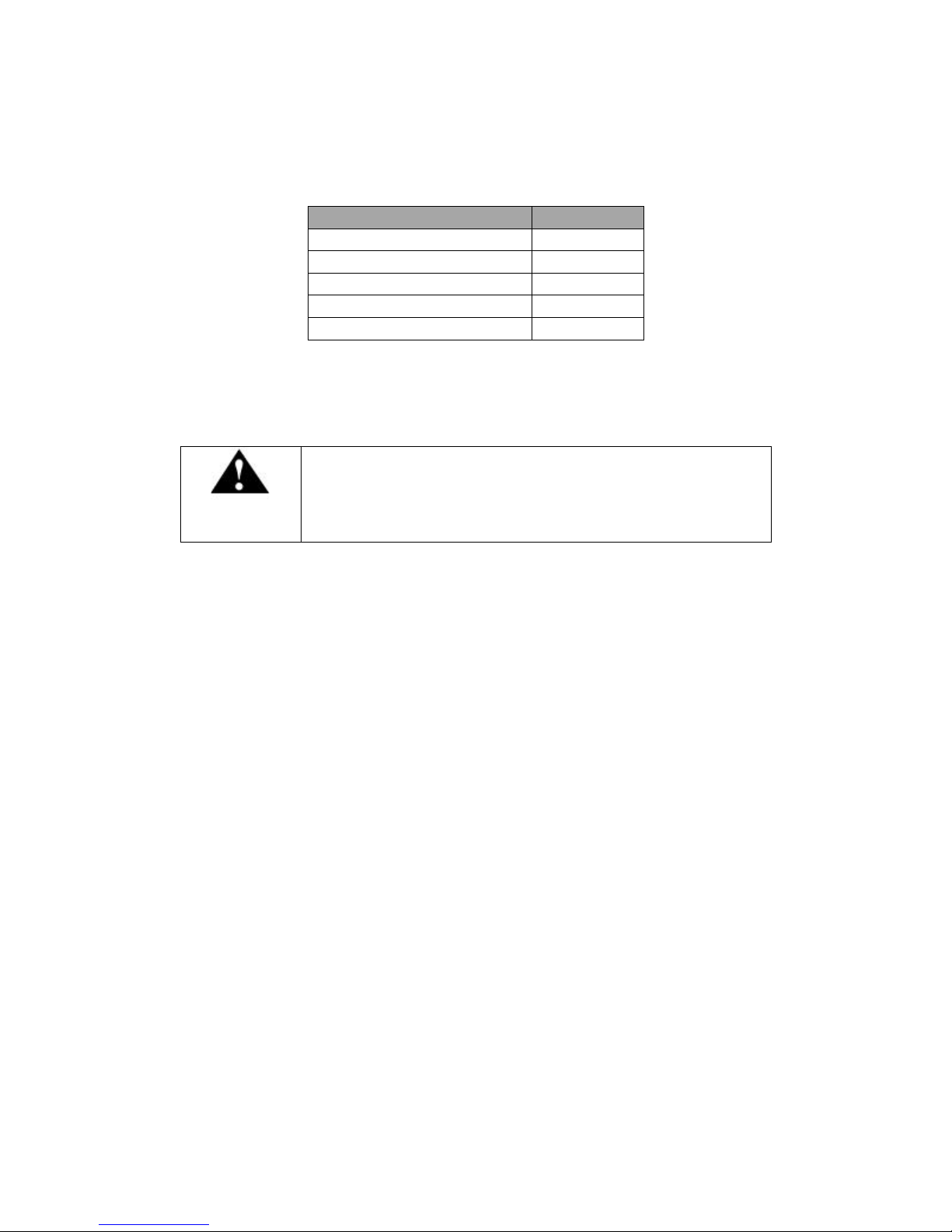
Table 1 lists the items included in the PRO1 shipping box.
Item Quantity
Receiver 1
Power Cord 1
Quick Start Guide 1
Installation Kit (Optional) 1
Network Data Sheet 1
Table 1. Packaging List
2.3 Safety Precautions
The following sections provide a list of general hazards to be
avoided for safe, reliable use of the PRO1 receiver.
Caution!
2.3.1 Excessive Temperature
The PRO1receiver has been designed to operate safely and reliably in an ambient
temperature of 0
○
C to 50○C. We expect the system to operate without the need for a fan
in air conditioned locations. The fan will be electronically controlled via a temperature
sensor which will allow the unit to operate under less than optimal conditions. It is
important to keep in mind that once the receiver is located in a closed or rack
environment, the ambient temperature may be greater than the room temperature. Please
take this into consideration when installing the receiver and make sure that the ambient
○
temperature around the receiver does not exceed 50
C.
2.3.2 Proper Ventilation
Air vents on the side and rear of the receiver are provided to ensure proper air flow
through the receiver unit. In order to ensure proper operation the PRO1 receiver should
be located such that its ventilation is not impeded. In a rack environment, at least two
inches on the sides and at least 5 inches in the rear should be provided. Proper ventilation
will help ensure the receiver performs both safely and efficiently.
2.3.3 Heat, Humidity, and Dust
XDS PRO1 Receiver User’s Guide
X-Digital Systems
Rev A - August 29, 2009
9
In order to avoid unnecessary internal damage, avoid placing the receiver next to external
heat sources such as heaters, direct sunlight, heating ducts, etc. Additionally, locations of
high humidity, dust, and vibration will be detrimental to the receiver’s performance and
longevity.
2.3.4 Power Cord Cabling
Avoid running the power cord across places of high traffic where it can be crimped or
tripped over. Make sure the cords are securely fastened to both the wall outlet or power
strip, and the back of the receiver. Do not place objects on or leaning against power
cords.
2.3.5 Proper Grounding
When the receiver is installed, make sure that the antenna and coaxial cable are properly
grounded to avoid static build up and voltage spikes which may occur due to lightning
strikes or other types of power surges. Proper earth grounding of the rack system should
be maintained at all times with special attention paid to any connections which go
through power strips.
Make sure all power strips are properly grounded.
Warning!
2.3.6 Circuit Overloading
The PRO1 receiver can draw up to 0.5 Amps at 120VAC as indicated on the back of the
receiver. When adding the receiver to an already existing rack setup, take care to ensure
the maximum current rating of the circuit is not exceeded.
2.3.7 Foreign Objects
Inserting any type of foreign object into the ventilation holes of the
receiver can result in shock or serious injury of the operator.
Warning!
If a foreign object is inserted into the receiver, immediately power down the receiver and
contact X-Digital Systems technical support. Do not open the receiver, as doing so will
void the receiver’s warranty.
XDS PRO1 Receiver User’s Guide
X-Digital Systems
Rev A - August 29, 2009
10
2.4 Physical Installation of the Receiver
The following section will guide you through the physical installation of the PRO1
receiver.
2.4.1 Rack Mounting the Receiver
The PRO1receiver has been specifically designed to fit into a 19-inch rack. There are
four screw holes provided on the front panel to directly mount the receiver in the rack.
All four screws must be in place after installing the receiver.
Do not paint mounting ears as it hinders the grounding path from
the receiver to the rack.
Caution!
2.4.2 Uneven Loading of Rack
When installing the PRO1 receiver into a rack, make sure to place heavier pieces of
equipment on the bottom and lighter pieces on the top.
Uneven loading may cause the rack to be unstable and
hazardous.
Caution!
2.5 Connecting to the Satellite Dish
This section contains information required for connecting your PRO1receiver to a
satellite downlink.
2.5.1 DC Voltage Requirement
You may need to have the PRO1 receiver supply DC voltage to either an LNB or a block
down-converter (used after an LNA). If this is the case, the user must change the
receiver’s LNB ON/OFF setting. If, however, you have another receiver that receives the
L-Band version of the satellite signal (950-1450MHz) then you may use a splitter with
XDS PRO1 Receiver User’s Guide
X-Digital Systems
Rev A - August 29, 2009
11

DC blocking circuitry to get the signal to the PRO1 receiver. In this case, the LNB
Voltage setting should be OFF.
2.5.2 Warnings About Shorting DC
If the LNB Voltage mode is enabled, be careful not to short the
signal. The voltage on this line is approximately +24V DC.
Caution!
If the DC Voltage is shorted during installation, transient voltage may damage the
Demodulator. In the case of a short, over-current protection circuitry will shut down the
LNB supply. When this occurs, it is important to disconnect the receiver as soon as
possible. If there is a “dead” short in the cable connecting the receiver to the satellite
dish, the unit will not function properly. Remove the power cord from the rear of the unit
and then check the cable connecting the receiver to the satellite dish to make sure it has
not been damaged and is installed correctly. Finally, reinstall the power cord and proceed
with unit setup.
2.6 Connecting to the Ethernet Network
The XDS PRO1 Satellite Receiver is specifically designed to receive audio broadcasts via
satellite transmissions. It is also equipped with an “internet” only mode in which is can
receive audio data and receiver updates via its Ethernet port. For this feature to be
functional, the receiver must be connected to a network router or directly connected to an
internet connection. This portion of the User’s Guide will provide instructions on setting
up your receiver to connect to the internet. If you are unsure about any of the values
required below, please contact your local network administrator for help.
2.6.1 Connecting the Cables
The Ethernet port on the back of the receiver accepts non-crossover RJ-45 cables.
Depending on your stations internet connection, you will either connect a RJ-45 cable
directly from a Cable or DSL modem box to the PRO1 receiver, or you will connect the
cable from a network router to the receiver. In either case, ensure that the cable is
properly aligned and that it clicks in when you connect it, so that it can not be removed
without pressing the plastic release button on the end of the cable. Ensure that your
internet connection is functioning before proceeding to the next steps.
2.6.2 Using DHCP or Static IP Addresses
Dynamic Host Configuration Protocol, or DHCP, allows the network administrator to
control the assignment of device IP address assignment. If DHCP is on, the receiver will
be assigned an IP address automatically by the network. The implications of this are that
XDS PRO1 Receiver User’s Guide
X-Digital Systems
Rev A - August 29, 2009
12

the IP of the receiver may change each time the receiver is rebooted. Turning DHCP off
will ensure that a static, or non-changing, IP is assigned to the receiver as opposed to a
dynamic one determined at each startup of the receiver. The IP address assigned to the
receiver can be found automatically using the xping discovery tool. For direction on
turning DHCP on or off, refer to Section 6.1.3. For instructions on finding the IP address
using the xping tool, refer to Section 5.
2.6.3 Assigning a TCP/IP Address
The TCP/IP address of the receiver serves as its identification number on the local
network. Once the receiver is set up properly on a network, it will host a website which
can be loaded by typing its IP address into any standard web browser. Therefore the
ability to specify a static IP address for the receiver may be useful. To view and modify
the IP address, refer to Section 6.1.3.
2.6.4 Assigning a Subnet Mask
The subnet mask is used to determine where the network number in an IP address ends
and the node number in an IP address begins. A node is any device on a network that
needs a unique IP address to communicate (computer, server, router, PRO1 Receiver,
etc.). To set this value for your purposes, refer to Section 6.1.3.
2.6.5 Assigning a Default Gateway
A gateway refers to a router or host which grants access to the internet. If you have not
enabled DHCP, you must specify the TCP/IP address of this default gateway. To set this
value, refer to Section 6.1.3.
2.6.6 Proxy Server Configuration
A proxy server can be configured through the Receiver Web Interface or through the
command line interface. To modify the proxy server through the command line, refer to
the E0/E1 PROXY commands in Section 4.2.2 or through the Receiver Web Interface
from Section 6.1.3.
2.6.7 DNS Server Configuration
The DNS Server settings must be configured using the Receiver Web Interface or
through the command line, see Section 4.2.2 and Section 6.1.3.
2.7 Connecting the Audio Port
XDS PRO1 Receiver User’s Guide
X-Digital Systems
Rev A - August 29, 2009
13

A live audio channel will physically connect the audio port of the PRO1 through the R/F
downlink. Networks will generally assign stations statically to an individual port or port
configurations can be modified through the Affiliate Website.
2.7.1 Analog Audio Port
The port on the back of the receiver labeled Audio A outputs analog audio. For
information on the pin-out of the port, please see Section 8.6.
2.8 Connecting the Relay Port
The PRO1 is equipped with one DB37F port labeled Relay A that is capable of receiving
cue signals from the Network signal and firing relay closures.
2.8.1 Physical Ports
The DB37F port on the back of the receiver has 16 relay closures that can be mapped.
The relay mappings can be modified, viewed and toggled through the Affiliate Website
(Section 7.3) or through the Receiver Web Interface . For pin-out information on the RS232 port please see Section 8.5.
2.8.2 Cues
The PRO1 is capable of firing multiple types of relays:
x Associated cues will fire when the associated program is playing. In addition
these cues will be recoded for delayed playback.
x Non-associated cues will fire if they are mapped to a relay regardless of what
program is playing.
x All cues will be outputted through an RS-232 Tx pin on the receiver’s relay port
to be used by downstream systems.
2.9 Connecting the Program Associated Data (PAD) Port
The PRO1 is capable of receiving and displaying PAD in two different ways. Your
Network will provide baud rate settings for the PAD. PAD settings for the receiver can
be configured through the Receiver Web Interface or the M&C (Section 4.2). PAD data
is output through the port labeled PAD on the back of the receiver. Please see section
Error! Reference source not found. for information on the PAD port pin-out.
2.9.1 In-Band Ancillary Data
XDS PRO1 Receiver User’s Guide
X-Digital Systems
Rev A - August 29, 2009
14

In-band ancillary data is raw asynchronous data embedded within the streaming audio on
the same program PID as the audio. It is fed into the RS232 port of the encoder port and
thereby associated with a single audio stream. MP2 natively supports ancillary data.
AAC will carry ancillary data in a proprietary enhancement to the framing protocol (this
enhancement will be compatible with all AAC decoders).
2.9.2 Out-of-Band Ancillary Data
Out-of-band ancillary data is raw asynchronous data associated with a single audio
stream but carried outside of the MP2 or AAC data frame. It is fed into the RS232 port
of the encoder port and thereby associated with a single audio stream. This data may be
embedded within the MPEG2 transport framing structure (TSP) of a single audio stream.
XDS PRO1 Receiver User’s Guide
X-Digital Systems
Rev A - August 29, 2009
15

3 Front Panel
The PRO1 receiver is equipped with four status LEDs that are indicative of the power,
signal, update and fault states of the receiver
3.1 Status LEDs
Each of the four status light-emitting diodes indicates a specific state of the receiver. The
following sections provide details on reading the status of the receiver based on the
LEDs.
3.1.1 The Power LED
The POWER LED is on when the unit is plugged in and there is no problem with the
internal circuitry.
3.1.2 The Signal LED
The SIGNAL LED is used to indicate whether or not the receiver has locked onto a
signal. The Signal LED will either be solid green if the receiver is locked or off if the
receiver is not receiving a signal.
3.1.3 The Update LED
The UPDATE led indicates a software download/upgrade is in progress. When it is
blinking slowly (once per second), the download is in process. When it blinks fast (three
times per second), an upgrade has been successfully installed and the receiver is ready to
be rebooted as soon as it is convenient.
The update LED will also be blinking if you haven’t activated your receiver unit with the
NMS. If the Ethernet is properly configured on your receiver, it should auto-activate.
3.1.4 The Fault LED
The FAULT LED has three possible states. A red Fault LED indicates that there is an
active fault condition affecting the receiver; a green Fault LED indicates that there is no
active fault, but that there is either an active warning or a past fault in the fault history; a
Fault LED that is off indicates that there are no current or past faults. The STATUS menu
(described below) will give you details as to which faults are active.
XDS PRO1 Receiver User’s Guide
X-Digital Systems
Rev A - August 29, 2009
16
 Loading...