

Page 1
X-Digital Systems XDS receiver
QUICK START GUIDE
REVIEW THIS GUIDE IN ITS ENTIRETY BEFORE INSTALLING
YOUR XDS RECEIVER. ALSO, FOLLOW THESE INSTRUCTIONS
BEFORE CALLING SUPPORT.
• Make all satellite RF, data (LAN/WAN) and audio connections
prior to applying AC power to the XDS receiver.
• Westwood One strongly recommends the use of a Phase Locked
Loop (PLL) LNB for your new XDS receiver. The Local Oscillator
(LO) stability of your LNB should not be above (worse than)
25kHz.
• If this XDS receiver is designated to supply DC power to the
LNB at your dish, be sure to turn on the LNB voltage on the
front panel menu AFTER the LNB is connected (See Satellite RF
Connection section 1.1 on page 2).
• Westwood One urges stations to use an Uninterruptible Power
Supply (UPS) for the XDS receiver for equipment protection
from power spikes or brownouts. Also consider lightning
protection if you are located in an area susceptible to frequent
lightning storms. Surge suppressors do not provide sufficient
protection.
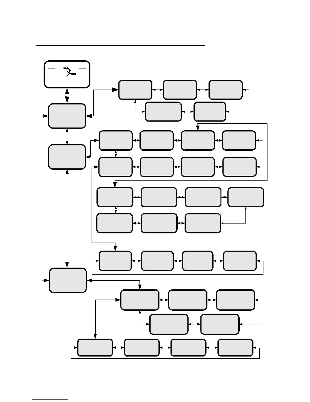
NOTE: Appendix A contains a front panel menu map that can help
navigate through the XDS receiver settings and configuration.
Revision J 9/30/2014 R830000-1060 Quick Start Guide, XDSPRO Receiver
Page 1 of 11
Page 2

1. MAKING THE CONNECTIONS
Satellite RF, data (LAN/WAN) and audio must be properly
connected. Please follow the steps below:
1.1 SATELLITE RF CONNECTION
Your XDS receiver is pre-tuned to the Westwood One carrier on AMC-8. Once the
satellite RF is properly connected and you apply AC power, the XDS receiver should
automatically tune and lock to the Westwood One carrier.
A. Connect the satellite RF to your downlink
Your new XDS receiver is delivered with a parts kit that includes two 6-foot RG-6
cables and an L-band splitter that allows DC power to pass through one port.
B. Verify the XDS receiver is tuned and locked to the WESTWOOD ONE
carrier
Once the satellite RF is properly connected, apply AC power to the receiver and
verify as follows:
• If the SIGNAL LED is green then the receiver is locked to the WESTWOOD
ONE carrier and the LCD screen will display:
(Cumulus Media / WWO Networks logo)
EB ##.# AG ### (# = numerical value)
EB should be above 7 and AG should be between about 40 and 60 for
proper operation.
• If the XDS receiver does not acquire the Westwood One carrier, the red
FAULT LED will illuminate steadily and the LCD screen will display:
(Cumulus Media / WWO Networks logo)
EB __._ AG ### (# = numerical value)
Verify proper RF connections and the XDS receiver should automatically
lock to the carrier.
To manually tune the XDS receiver to Westwood One carrier on AMC-8:
Revision J 9/30/2014 R830000-1060 Quick Start Guide, XDSPRO Receiver
Page 2 of 11
Page 3
If the front panel of your XDS receiver displays flashing red
o At the main screen with the Cumulus Media Networks logo, press the SET
key, then the left or right arrow keys to reach Setup. Press SET.
o Press the left or right arrow keys to reach Tuner. Press SET.
o Press the left or right arrow keys to reach Frequency. Press SET.
o Use the four arrow keys and the SET key to set the frequency to
01000500 kHz
o Press the left or right arrow keys to reach Symbol Rate. Press SET. Use
the four arrow keys and the SET key to set the symbol rate to
09259574 sps
The XDSPRO receiver should lock. (Green SIGNAL LED will illuminate
steadily).
If this XDS receiver is designated to supply DC power to the LNB at your dish, you
can turn on the LNB voltage on the XDS receiver front panel menu as follows:
• Make sure your downlink LNB is connected to the XDS receiver
• Apply AC power to the receiver
o From the main screen with the Cumulus Media Networks logo, press the SET
key, then press the left or right arrows to reach Setup. Press SET.
o Press the left or right arrows to reach Tuner. Press SET.
o Press the left or right arrows to reach LNBV, Press SET and turn the LNB
Voltage on.
lights, this indicates all Activation and Installation steps have
not been completed and/or your XDS receiver is not connected
to the internet. All Activation and Installation steps, including
your internet connection, must be completed or you will NOT
receive Westwood One programming. Your XDS receiver must
ALWAYS be connected to the internet 24/7/365.
Revision J 9/30/2014 R830000-1060 Quick Start Guide, XDSPRO Receiver
Page 3 of 11
Page 4

1.2 AUDIO OUTPUT CONNECTIONS
Once the XDS receiver is locked to the Westwood One carrier you can verify audio
functionality as follows:
A. Verify audio reception
Initially the XDS receiver headphone output and all the audio ports are programmed to
receive the Test Channel.
Connect a set of headphones and verify you can hear the Test Channel.
To manually program the XDS receiver headphone to output the Test Channel:
o At the main screen with the Cumulus Media Networks logo, press the SET
key, then the left or right arrows to reach Audio Ports. Press SET.
o Press the left or right arrows to reach Headphones. Press SET.
o Press the left or right arrows to reach Program. Press SET.
o Use the up and down arrows to find Test Channel. Press SET.
B. Verify audio ports
Your new XDS receiver is delivered with a parts kit including four mating DB-9
connectors with shells.
The analog audio outputs for your services appear at the four DB-9 connectors on
the rear panel. Wiring pinouts are the same as on the older Starguide receivers:
1
2
3
4
5
AUDIO OUTPUT – DB9M
Pin Signal Signal Pin
Rule: Each DB-9 connector carries one radio program stream, either mono or
stereo. If the program is mono, the same audio appears on the left and right pin
pairs. In most cases, the left and right sides of a stereo channel are no longer
used by Westwood One to carry unrelated mono programs. Other networks and
distributors may use different rules.
Revision J 9/30/2014 R830000-1060 Quick Start Guide, XDSPRO Receiver
Page 4 of 11
L+ L- 6
GND GND 7
- - 8
GND R- 9
R+
Page 5

Your receiver should be pre-configured to output the Test Channel on all ports.
Verify you can hear the test program through all receiver ports.
To manually program the XDS receiver to output the Test Channel on a desired audio
port:
o At the main screen with the Cumulus Media Networks logo, press the SET
key, then the left or right arrows to reach Audio Ports. Press SET.
o Press the left or right arrows to select the Audio Port (letter A, B, C or D).
Press SET.
o Press the left or right arrows to select Program. Press SET.
o Use the up and down arrows to find Test Channel. Press SET.
1.3 INTERNET CONNECTION
This new XDS receiver requires connection to an always-on internet pathway. The
internet pathway is used by Westwood One to troubleshoot remotely, send audio or
text content to your receiver’s storage, send commercial playback schedules, retrieve
as-played logs of commercials inserted by the receiver, and more.
Your XDS receiver is delivered with a 20-foot Category 5 data patch cord wired “straight
through” (not crossover) for connection to your networks hub or switch.
A. Connect the XDS Receiver to your network
If you elect to place your XDS receiver in your local network “inside” your
firewall, connect your network cable to one of the receiver’s LAN ports. The
receiver is set by default to obtain a dynamic IP address, also called a “DHCP
address”, from your network’s DHCP server. If there is no DHCP server or you
elect to assign a static IP address, you can do it as follows:
Assigning a Static IP address to a LAN Port:
o At the main screen with the Cumulus Media Networks logo, press the SET
key, then the left or right arrow keys to reach Setup. Press SET.
o Press the left or right arrow keys to reach Network. Press SET.
o The default settings for DHCP is ON. Use the SET and arrow keys to change
DHCP from ON to OFF.
o Press the left or right arrow keys to go to the LAN Address menu. Press SET.
o Use the up and down arrow keys and the SET key to set the desired IP
address.
o Press the left or right arrow keys to go to the LAN Subnet menu. Press SET.
o Use the up and down arrow keys and the SET key to set the desired subnet
address.
o Press the left and right arrows to go to the Gateway menu and press SET.
o Use the up and down arrow keys and the SET key to set the desired gateway
address.
Revision J 9/30/2014 R830000-1060 Quick Start Guide, XDSPRO Receiver
Page 5 of 11
Page 6

Assigning a Static IP address to the WAN Port:
If you elect to connect your receiver in a firewall zone called a “DMZ”
(demilitarized zone) or ‘“Outside” the firewall where it can see the internet
directly, connect your network cable to the receiver’s WAN port. You must
assign a static IP WAN Address, WAN Subnet, and Gateway. Follow the
“Assigning a Static IP address to a LAN Port” instructions above to go to the
appropriate WAN menus and change settings as desired.
NOTE: If your network requires the use of a proxy server, please refer to the
online user’s guide located at your affiliate’s website. Refer to Section 2 on page
7 for instructions on how to login to you your website.
B. Test connection to the Westwood One NOC
o At the main screen with the Cumulus Media Networks logo, press the SET
key, then the left or right arrow keys to reach Setup. Press SET.
o Press the left or right arrow keys to reach Network. Press SET.
o Press the left or right arrow keys to TEST NOC. Press SET.
o Press the NOC softkey to perform the test.
The test will take a minute or two. You will get a SUCCESFULLY CONNECTED
TO NOC message if your IP settings are correct. Otherwise you will get a
CANNOT CONNECT TO NOC message and you will need to adjust your IP
settings (on the receiver, or in your network’s switches, routers or firewall) until
the receiver can connect to the NOC.
To troubleshoot, you can use the PING softkey to verify your receiver can locally
connect to your network gateway.
1.4 AUTOMATION RELAY CLOSURES
There are two DB-37 connectors on the rear panel which together contain a total of 32
mappable relay (or contact) closures to drive your station automation.
Your XDS receiver is delivered with a parts kit including two mating DB-37 connectors
with shells.
Revision J 9/30/2014 R830000-1060 Quick Start Guide, XDSPRO Receiver
Page 6 of 11
Page 7
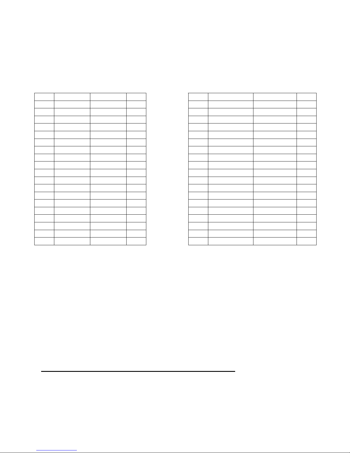
NOTE: Wiring pinout for the RELAY A port is the same as on the StarGuide receiver
with Westwood One Netcue Card.
The pinouts for the DB-37 connectors are:
RELAY A - DB37M
Pin Signal Signal Pin
1
RLY1A RLY1B 20 1
2
RLY2A RLY2B 21 2
3
RLY3A RLY3B 22 3
4
RLY4A RLY4B 23 4
5
6
7
8
9
10
11
12 RLY10A RLY11B 31 12
13 RLY11A RLY12B 32 13
14 RLY12A GND 33 14
15
16 RLY13A RLY14B 35 16
17 RLY14A RLY15B 36 17
18 RLY15A RLY16B 37 18
19 RLY16A 19
GND GND 24 5
RLY5A RLY5B 25 6
RLY6A RLY6B 26 7
RLY7A RLY7B 27 8
RLY8A RLY8B 28 9
GND RLY9B 29 10
RLY9A RLY10B 30 11
NQ Txd
RLY13B 34 15
RELAY B - DB37M
Pin Signal Signal Pin
RLY1A RLY1B 20
RLY2A RLY2B 21
RLY3A RLY3B 22
RLY4A RLY4B 23
GND GND 24
RLY5A RLY5B 25
RLY6A RLY6B 26
RLY7A RLY7B 27
RLY8A RLY8B 28
GND RLY9B 29
RLY9A RLY10B 30
RLY10A RLY11B 31
RLY11A RLY12B 32
RLY12A GND 33
NC RLY13B 34
RLY13A RLY14B 35
RLY14A RLY15B 36
RLY15A RLY16B 37
RLY16A
If you or your automation vendor has developed a program that can read Westwood
One Netcues directly, you may get the Netcue serial stream from pins 15 and 10 on the
Relay A port on your XDS receiver (see pinout above). The “NQ TxD” pin is RS-232
data with no flow control or handshaking. Baud rate is set by default to 9600 bps 8N1.
THREE CHARACTER NETCUES:
If you currently use a Netcue/Data card in your Starguide receiver, any 3-character
Netcue that Westwood One sends out can be mapped to any contact closure you wish.
Contact
our Technical Services department or contract Help Desk to help you map your existing
Netcues to the same relay pins on one of the DB-37 connectors on your new XDS
receiver.
2. VERIFY PROGRAMMING AND ACTIVATE
In the XDS system each program, not each channel, is permissioned and labeled for
station use. Therefore, instead of tuning to a channel to find a program, you will
Revision J 9/30/2014 R830000-1060 Quick Start Guide, XDSPRO Receiver
Page 7 of 11
Page 8

schedule the programs to appear on each output port. You will need to review your
schedule and activate your receiver with your stations programming.
Initially your receiver only outputs the Test Channel on all ports, the front panel LCD
shows a “Please Activate” message and the orange UPDATE LED in flashing.
You must edit and activate the schedule of the programs that you want to appear on
each audio output port of the XDS receiver through the WESTWOOD ONE Affiliate
website at
http://myxdsreceiver.cmneng.com
To login you will use the XDS receiver’s serial number as the username and a password
generated by the receiver. To find this password:
o At the main screen with the Cumulus Media Networks logo, press the SET
key, then the left or right arrows to reach Setup. Press SET.
o Press the left or right arrows to select Serial Number.
o Press the PWD softkey to display your password.
Once logged in, you may setup a friendly password to the site and also review and
approve your receiver’s setup (Time Zone, Schedule, Relay Mappings, etc).
Adjust Time Zone
Setup the appropriate time zone for your receiver
Review Schedule
You will see the default schedule for every station your receiver supports. Please modify
and verify your schedule as desired.
RULE: Each call-letter radio station at your site that carries any Westwood One
programming or commercials from this XDS receiver must be assigned to an XDS
receiver port and each port must be scheduled to output the programs you need.
NOTE: Your new XDS receiver contains about 32 hours of audio storage which you may
use to “tape delay” network programs and schedule them to play later. You can
schedule the same XDS receiver port to “play back” a mixed schedule of live and
delayed programs.
Revision J 9/30/2014 R830000-1060 Quick Start Guide, XDSPRO Receiver
Page 8 of 11
Page 9

Review Relay Mappings
You will see the default relay mapping configuration for your receiver. Please modify
and verify your mappings as desired.
Approve Setup and Activate
Once you reviewed all your desired settings, check the APPROVE SETUP AND
ACTIVATE box, press the UPDATE button, and the NOC will send the updated
programming to your receiver.
It may take a couple of minutes for the XDS receiver to download the Westwood One
programming information. To verify your receiver is activated, the UPDATE LED will
turn off and the front panel LCD will display the “XDSPRO” message instead of the
“Please Activate” message
3. SUPPORT CONTACT INFORMATION
If you have any problems please call Westwood One Technical Services and they will
help you set up and verify your receiver.
The Westwood One Technical Services office is staffed Monday to Friday from
9:00 AM to 6:00 PM ET for technical assistance.
Westwood One | Technical Services
100 Manhattanville Road, Suite 11
Purchase, N.Y. 10577
Phone : (914) 908-3210
Fax : (914) 305-9846
E-MAIL: [email protected]
Revision J 9/30/2014 R830000-1060 Quick Start Guide, XDSPRO Receiver
Page 9 of 11
Page 10
APPENDIX A – XDS RECEIVER MENU MAP
EB AG
XDS PRO4
XDS PRO4
Status
XDS PRO4
Setup
L/R
U/D
L/R
L/R
U/D
U/D
Setup
Serial Number
XDSP-000000
L/R
Setup
Tuner
Setup Network
DHCP
L/R
Setup Network
Test NOC
Active Faults
OK
Storage Status
L/R
Total: 3884MB
Avail: 3683 MB
Setup
L/R L/R
L/R
M&C Ports
115K,8,None,1
Setup
L/R
Relays
Setup Network
L/R L/R L/R
LAN Address
Setup Network
Gateway
Fault History Environment
L/R L/R
L/R
L/RL/R
L/RL/R
Power Status
1.2V=1.21
5.0V=5.09
Setup
Network
Setup
Factory Defaults
Setup Network
LAN Subnet
Setup Network
WAN Subnet
Temp: 39°C
Fan: HIGH
Setup
L/R
Alarms
0FFBDFFF
Setup
L/R
Version
Setup Network
WAN Address
U/D
L/R
L/R
Setup
Frequency
XDS PRO4
Audio Port
U/D
U/D
Audio Port #
Program
Revision J 9/30/2014 R830000-1060 Quick Start Guide, XDSPRO Receiver
Page 10 of 11
Setup
L/R L/R L/R
Symbol Rate
Audio Port A Audio Port B Audio Port C
L/R
L/R L/R L/RL/R
Audio Port #
Spot
L/R L/R L/R
Setup
FEC
L/R
L/R
Audio Port #
Settings
Audio Port DHeadphones
Setup
LNB Power
Audio Port #
Station
Page 11
Important Notice
Users Manual
The XDS-PRO4 DVB Satellite Receiver Users Manual is available on-line. To access the Manual, please log-on to
http://myxdsreceiver.cmneng.com with your Affiliate’s web page access information, go to Help, and select: Users
Manual. If you have any questions, please contact your Affiliate Station, or the Help Desk.
FCC Compliance
T
HIS DEVICE COMPLIES WITH PART 15 OF THE
(1) T
HIS DEVICE MAY NOT CAUSE HARMFUL INTERFERENCE; AND
INTERFERENCE THAT MAY CAUSE UNDESIRED OPERATION
UL and CSA Compliance
T
HE
XDS-PRO4 DVB S
T
HIS DEVICE MEETS THE SAFETY AND TEST REQUIREMENTS OF THE TEST SPECIFICATIONS, AND WAS FOUND TO BE IN COMPLIANCE WITH
PROTECTION AIMS OF THE APPLICABLE
R
ECEIVER MAY BE MARKED WITH THE
ATELLITE RECEIVER WAS TESTED ACCORDING TO UL
TUV
FCC
RULES. OPERATION OF THIS DEVICE IS SUBJECT TO THE FOLLOWING TWO CONDITIONS:
(2)
THIS DEVICE MUST ACCEPT ANY INTERFERENCE RECEIVED, INCLUDING
.
60950-1:2003
EC-
DIRECTIVES AND THE REQUIREMENTS OF THE STANDARDS. THE
MARK AS SHOWN BELOW; CERTIFICATE NO. U8 07 01
AND
62269 001
Warning! Approved external telecom power
cross protection must be
incorporated into the final
installation in accordance with
Annex NAC of UL/CSA standard
60950-1. Failure to comply may
result in a fire or electric shock
hazard and will void regulatory
compliance certification.
CSA C22.2 NO. 60950-1:2003.
XDS-PRO4 DVB S
ATELLITE
Acknowledge of Trademarks
Any product or corporate names used herein may be trademarks or registered trademarks, and are only used for
identification and explanation, without intent to infringe. Any terms mentioned or used that are known trademarks
or service marks have been appropriately capitalized and italicized. X-Digital Systems, Inc. cannot attest to the
accuracy of this information. Use of a term in this document should not be regarded as affecting the validity of any
trademark or service mark.
Patent Pending
X-Digital Systems, Inc., DVB Satellite Receiver – Patents Pending
Disclaimer
This document is intended to provide information about the “XDS-PRO4 DVB Satellite Receiver”. Every effort has
been made to make this document as complete and accurate as possible, but no warranty or fitness is implied. The
information is provided on an “as is” basis and X-Digital Systems shall have neither liability nor responsibility to any
person or entity with respect to any loss or damages arising from the information contained in this document.
Warning!
Approved external telecom power cross protection must be incorporated into the final installation in accordance with
Annex NAC of UL/CSA standard 60950-1. Failure to comply may result in a fire or electric shock hazard and will void
regulatory compliance certification.
Revision J 9/30/2014 R830000-1060 Quick Start Guide, XDSPRO Receiver
Page 11 of 11
 Loading...