

Page 1

ULTIMATE 2
SLED
BY
XCS INC.
MANUAL
Rev.2.3
1/14
Page 2

0S 304
1-14 Vdc+
2-Ground
3-Ground
4-14 Vdc+
1S 303
1-28 Vdc+
2-Ground
3-14 Vdc+
2B 302
1-14 Vdc+
2-Ground
0B 304
1-Ground
2-14Vdc+
3-Video signal
4-Video gnd.
2B 303
1-28 Vdc+
2-Ground
3-14Vdc+
Upper Camera Platform /Lower electronics housing connectors.
Because our sleds are completely customizable some connectors and placement can vary.
Camera platform rear view
Camera platform left side view
Camera platform right/left side
0B 304
1-Ground
2-14 Vdc+
3-Video signal
4-Video gnd
9mm tapped plugged hole for
0B Lemo X3
Often used for 2 pin Tally
connector
Lower electronics housing front view
1B 308
1-Power gnd.
2-14 Vdc+
3-Video signal
4-Video gnd.
5,6,7 not connected
8-Video out from
recorder deck.
0B 304
1-Ground
2-14Vdc+
3-Video
signal
4-Video gnd
HDSDI loop
through
0.375” hole
with plug X2
Often used for 2 pin tally
connector and 2nd HD line
0S 304
1-14 Vdc+
2-Ground
3-Ground
4-14 Vdc+
1S 303
1-28 Vdc+
2-Ground
3-14 Vdc+
Composite Video 0S 304 0S 303 HDSDI Video
In only loop through
75 Ohm only
Page 3

Warranty
Please read before using your equipment
Xtended Camera Support will warranty this product against defects in material and workmanship
for a period of one year from the date of invoice. XCS will pay parts and labor charges to repair or
replace any manufacturers defect under normal operating conditions. The buyer will be responsible for all
shipping charges.
This warranty does not cover, nor will the manufacturer be responsible for, damages caused from
abuse, misuse, negligence, accidents, cosmetic damage, or by acts of God. All warranties expressed or
written will be voided if this equipment has been damaged by abuse, misuse, negligence, or accident.
Great care in engineering design has been made resulting in no serviceable parts inside this sled
and monitor. Care must be taken when using all your equipment. One should protect it from water, dirt,
shock, and excessive heat. Proper care of your equipment should be mandatory in your mind. After all, if
the equipment fails, you stop working.
If you have any questions on care for any of this equipment, please call XCS and we will be glad
to advise you on any maintenance of our equipment.
Proper care should be taken when shipping your equipment to protect it from shock damage. At
least 2.0” of a 4 lbs. Ester foam (or equal) should surround your equipment at all times when shipping.
Case design is made so that the case will absorb the impact and the case will give up its life, protecting
the equipment inside.
Unlike any sled ever designed before, it takes a special and knowledgeable operator to
understand the technical hurdles and advancements made with the Ultimate sleds. We thank you for
choosing it. We understand you have many options for sleds out there, and most of them are less
expensive to purchase. However, an informed operator can quickly weed out all the competition, on
every design feature, and only one manufacturer stands alone.
With proper care, this equipment will provide you with many years of service. Thank you for
choosing Xtended Camera Support. We have only the operator in mind for all our designs.
* The use of 50Ω plugs will permanently damage all the HDSDI connectors on the unit. The use of 50Ω plugs is considered to
be misuse of the equipment and will therefore invalidate the unit’s warranty. Please check and update those old BNC cables
there is no place in the HD world for them.
1
Page 4

UPPER CAMERA PLATFORM
Composite video in
12Vdc FI&Z power only
12/24 accessory pwr. 2 amp max
HDSDI / Composite
loop through
12 Vdc camera
12 Vdc / video out for transmitter
12/24 Vdc camera power
9mm
tapped/plug
hole
Low profile design “drop in” style upper camera platform (UCP). A single quick locking clamp secures
the camera plate in seconds. You will also notice that there is no flexing anywhere in this design. After 10
years of operating the system design I have yet to see any vibration transmitted to the camera, no matter
the weight, speed of travel, camera angle, or directional changes. The UCP design, however, is only part
of the overall design that makes this system’s stability second to none.
The quick release upper camera platform is simply removed by unscrewing the locking ring and lifting off
the post. Cable connectors are keyed so when reattaching the post and platform simply spin the post a
few degrees allowing the interconnection. The post mount is keyed and fits into the registration pin. Make
sure you securely tighten down the knurled locking ring, no tools are needed, hand tight is all you will
need.
There is no need to over tighten the Kipp handled dovetailed locking clamp. The Urethane on the face
of the clamp will hold the camera plate with light pressure. Over time you will need to replace this Kipp
handle, 2 years on average. The stud is made from a soft zinc steel, the insert in the stage is hardened
stainless steel. By design, the Kipp handle’s stud will wear out first. After a few years, if you are having to
over tighten the Kipp handle and the dovetail is sliding in the platform or the clamp is hanging up on the
stainless steel shoulder bolts, you will need to simply adjust the two set screws that keep the clamp in
alignment. They are located on the side of the clamp. (See Adjusting dovetail clamp)
It takes only 3.5 revolutions to go from fully engaged to fully open on the Kipp handles 10-32 TPI stud to
engage the camera dovetail plate. It takes ¾-1 revolution to loosen the camera plate. I mention this
because in low mode you will not want to turn the Kipp handle more than two revolutions.
On the three 6-32 tapped holes for the receiver bracket on the front of the platform the screw should not
exceed .25” into the platform.
Front view Rear view
1
All composite video inputs and outs are correctly wired through distribution amplifiers, using 75 ohm
conductors. The HDSDI BNC loops through to the lower electronics housing HD BNC connector. This
bypasses the sled electronics.
2
Page 5

Left side view Bottom view
Two clamp adjustment set
screws
10-32 TPI Kipp locking handle
Knurled locking ring
Center post alignment pin
3
Camera plate
The XCS camera plate design is unique in a multitude of ways. Unlike other plates it will not flex.
One plate design fits all current camera designs. You have three 15 mm rod holes in the front of the plate
for motors. Over 5.0” of Fore & Aft travel for balance. A dovetail at the rear of the plate for our transmitter
bracket keeps your video transmitter at the highest point. There two additional dovetails on the lower
electronics housing for the transmitter bracket when working in low mode. Two .375 x 16 TPI tapped
holes for the camera screws.
The left-right sliding camera plate is the most flexible camera plate ever designed . You used to
have a specific screw hole that you placed the camera screw into. With slots you have greater flexibility in
placing the camera plate on the cameras center of balance. Add the flexibility of the sliding plate, you will
never again has to worry about finding a center balance. You will find ENG video cameras, Sony P5,55,
Arri SR’s, and Aaton are all down the center of the plate. Alexa, F65 Panavision, Arri, and Moviecam are
all camera right side heavy, so the camera plate when screwed into the base will be off towards the
camera right side a bit, 3/16
finding the camera plate placement is no different than when you had to learn the method of which screw
hole to use. With the addition of the sliding camera plate it doesn’t have to be perfect, you have more left
to right adjustment then any sled system. You also as you have your fine balance adjustments at the
bottom of the Lower Electronics Housing (LEH).
th
’s to .25” would be average. In the beginning of ownership getting used to
Page 6
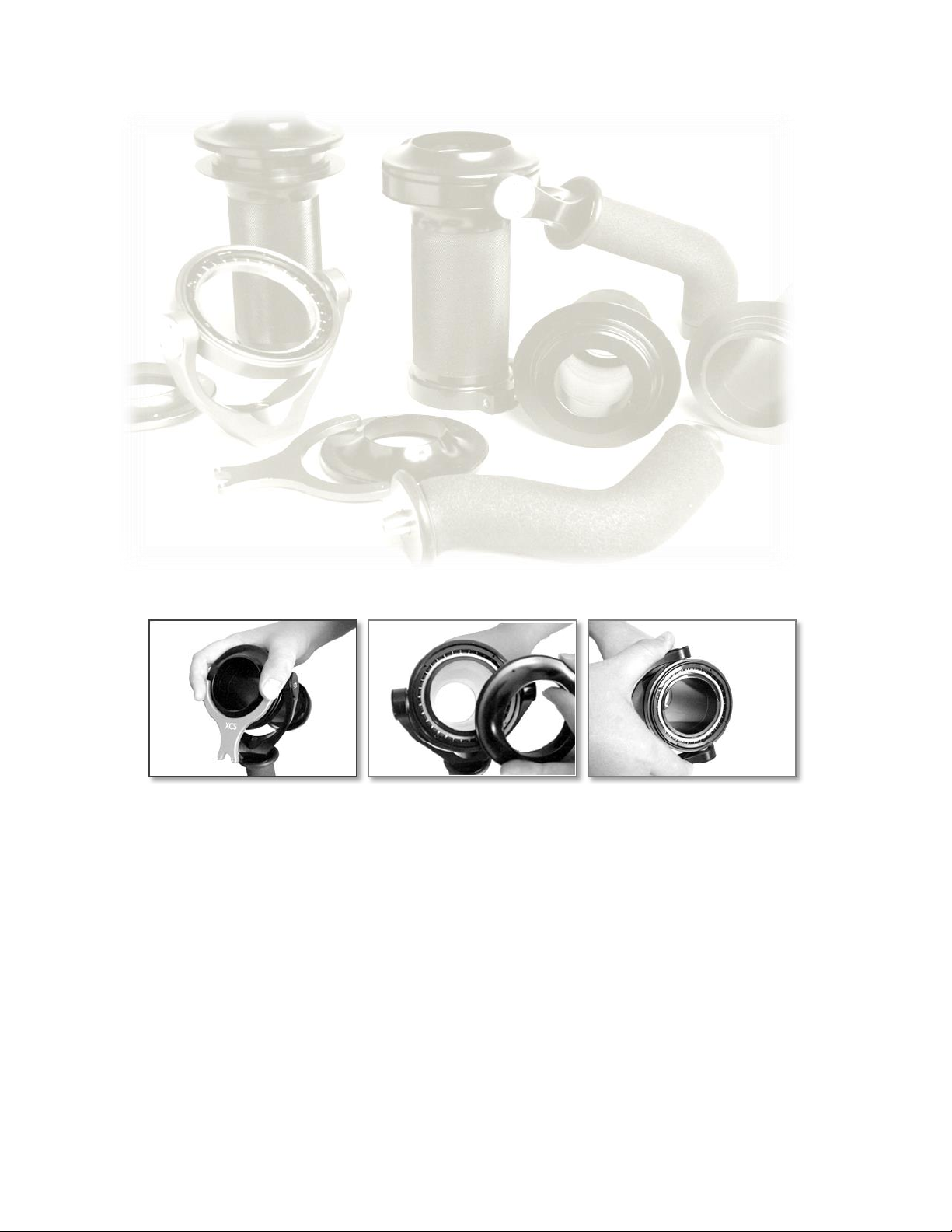
ULTIMATE GIMBAL
Your no tools adjustable gimbal is the most precision designed gimbal ever in the steadicam
industry. Care should be taken so it will provide you with many years of service and reliability. Be careful
not to drop or bend your gimbal fork.
There is not much to tell you about when it comes to the gimbal. To adjust the gimbal up or down
the post, simply turn the Kipp handle to loosen and move the gimbal into position, and retighten. You do
not have to over tighten a gimbal lock on the carbon fiber post. Snug is generally significant enough and
does not need as much force as you might be used to on metal posts.
When making very fine gimbal balance adjustments, I have learned that by turning the gimbal
sleeve a little bit like a screw, that this helps make small adjustments very precise.
One of the unique gimbal sleeve design features is the symmetrical contours on the cap. This
gives the operator the same feel when operating in either high or low mode. The symmetrical fork design
allows considerably more hand room under the gimbal fork in normal mode and you will never have to
worry about pinching your thumb on the fork in low mode. Precise alignment of all three axis, no tools
balance adjustment, complete interchangeability has made this gimbal the most popular gimbal on the
market.
On the standard 115 degree handle is the 10-32 locking screw which is used for tightening the
gimbal handle onto your post in low mode.
Under the foam grip is the standard .1875” through hole in this handle, if you like to use a safety
pin .
If you are using the Ergo handle you will not need the locking screw because you do not flip the
handle over for low mode work.
Gimbal Cleaning & Care
You will find that you most likely will not be disassembling your gimbal and cleaning it very often.
In fact it may be years before you would need to do it, if at all.
Place gimbal wrench pins in two of the matching holes on the gimbal cover.
Hold down on gimbal wrench as picture shows and turn to remove gimbal dust cover. A light tap
with a plastic screwdriver handle may be necessary.
Hold the gimbal upright when removing cap so not to have the fork and bearing cup fall off the
gimbal sleeve. Using the same gimbal wrench, remove the side dust covers on the gimbal fork.
This will reveal the two fork bearings. It is not necessary or recommended to remove the
bearings from the gimbal fork or bearing cup during cleaning, nor is it necessary.
When removing the fork & bearing cap from sleeve be careful to slide it off evenly. It is a perfect
fit. DO NOT PRY OR TAP THE FORK OR BEARING TO REMOVE OR DISASSEMBLE FROM
SLEEVE. If the bearing does not remove from sleeve smoothly, put it in the freezer for 20-30
minutes, this will allow the bearing to be easily removed from the gimbal sleeve.
I find cleaning the bearings using a pressurized non-lubricated spray contact cleaner works
perfectly. You can also use an automotive pressurized can of spray carburetor or brake cleaner.
Be advised to wear eye protection when using any pressurized cleaner. I would spray the bearing
and spin them three or four times to remove any dirt and excess cleaner.
4
Page 7

Lubricate with the oil of your choice. We use a Castro synthetic lubricant, but any type of
lubrication will work. Place a few drops on all the bearings and spin the bearings to work the oil
into the bearing cage. This oil will fly out when you spin it, so be forewarned.
Wipe clean the bearing journal on the gimbal sleeve. Wipe on a small amount of lubricant for
easier assembly of the bearing onto the journal. Insert the bearing cup onto the gimbal sleeve
and reassemble in reverse order. Once again I would give a light tap on the gimbal wrench to
tighten the cap on the sleeve.
We do not use, and do not recommend using, any type of thread locker on these threads.
Gimbal handle removal, replacement
Before you replace your gimbal handle, take your new handle and inspect the spindle end
(tapered end portion that fits into the gimbal fork). Make sure the tapered portion has no dents,
scratches, or marring of any kind. If it does, do not use this spindle.
To remove the handle, please follow the instructions below.
Remove gimbal from the sled post. With clamping end of the gimbal facing up, insert 9” hex head
wrench provided through the gimbal handle sleeve into the hex head screw in the gimbal fork.
Remove the screw that holds the fork on the gimbal handle and set it aside. The fork should
separate from the spindle cleanly. If the handle is stuck on the spindle, you might re-insert the
screw half way and tap the top of the hex head wrench. This will disengage the stainless steel
spindle shaft from the fork.
Reassemble in reverse order. You do not have to use Loctite on the 10-32 screw that attaches
the fork to the handle, but if you decide to, use a non-permanent Loctite (purple) on the gimbal
fork screw. Do not over tighten this screw. The recommended maximum inch/pounds is 28 on
this stainless steel screw.
What to do if the spindle is turning while you turn the hex head screw.
If this occurs, press down slightly on the fork with your index and middle finger next to the hex
head screw as you turn the wrench. This will put slight pressure on the spindle and hold it while you
loosen the screw.
Other notes:
We use a Heilcoil insert on the threads of the gimbal sleeve to prevent possible damage to the
sleeve itself. If you replace the Kipp handle, we recommend not using hardened steel screws - soft zinc
is the best choice. Over a period of time these could damage the thread insert.
If you wish to remove the Kipp handle and use a standard hex head screw, a 10-32 TPI screw
size and .625” long should work fine.
5
Page 8
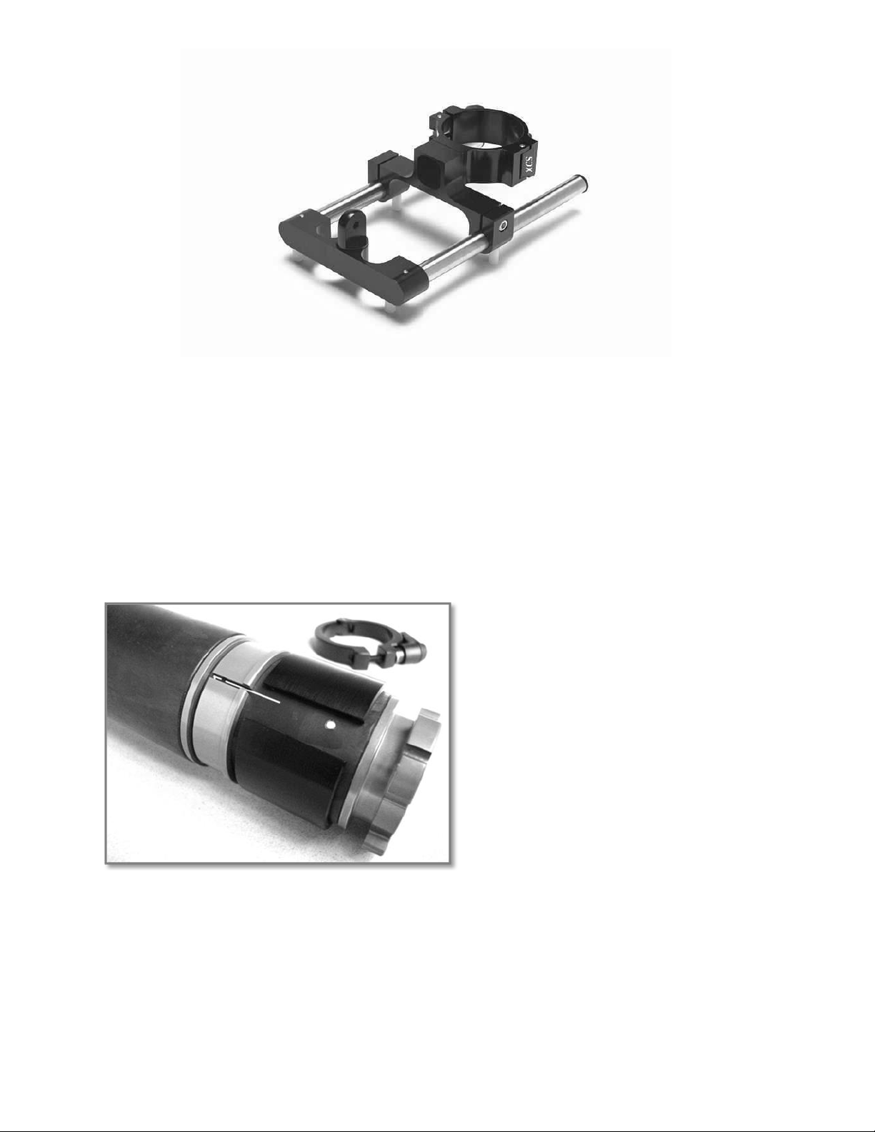
The design allows the user to expand the masses of the sled allowing greater stability in any
system. By moving your monitor and batteries in /out decreases /increases your panning inertia allowing
your system to glide along when expanded, or whippy when compressed. The two hex head screws on the
side of the clamp when loosened, allows you to move your monitor in and out.
When flipping your monitor into low mode, operators need only to loosen the Kipp handle on the
center post clamp, then flip your monitor over and reattach the clamp.
There is an 8-32 Phillips FHMS located on the inside of the post clamp. If you wish to have the
locking clamp rotated to the other side, simply loosen the Phillips head screw, remove the split clamp, flip it
180 degrees and press it on lightly, and attach the screw with a bit of nonpermanent Loctite.
Once again we use 10-32 TPI Kipp handles on the sled. If you wish to replace the Kipp handles you will
need the 10-32 TPI screws, different lengths for different applications. A set of these spare screws are
provided with the sled.
Dual Rod Monitor Support Arm
XCS
2” Telescoping Carbon Fiber Post
Bayonet mounted means never before has
changing center posts been so easy.
When disconnecting from the UPC you will
need to unscrew the knurled ring completely.
When disconnecting from the LEH you need
only to turn the knurled ring 60 degrees and
pull up on the post. When connecting or
disconnecting the center post, there is never
any need to connect or disconnect wires
inside the post. The post itself contains a
custom designed cable with 16 conductors.
The coiled cable contains correct wire gauge
sizes for power, video coax and signal wires.
The multi-layered custom wound post assures maximum post rigidity and feeling of solidness like never
before. Currently this post design is up to 15X more rigid than current aluminum designs. To extend the
post you simply need to loosen the center post clamp and side in or out, retighten the clamp when set to
length. There is a slot in the aluminum reducer ring that aligns to the ruler mark on the inner post. This
allows the UPC and Lower Electronics Housing (LEH) to stay in alignment. There is a safety stop in the
inner post preventing the post from sliding apart.
6
Page 9
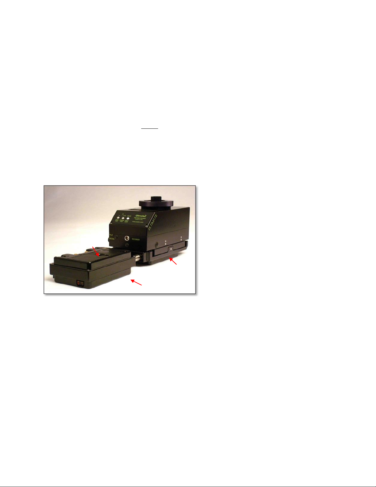
The internal cable and connector are designed to spin and slide in and out. We changed from a
Battery plate 1
Plate 2
Plate 3
fixed connector design to make it field serviceable. If the cable slides out the bayonet end it will pop back
into the bayonet mount.
To assure maximum integrity in the center post, there are no slots or grooves cut into the inner or
outer posts. It would be possible to spin the outer post around the inner post, uncoiling the inner-coiled
cable when connected to the LEH & UCP, and eventually this would make telescoping and contracting
difficult. Be cautious in trying not to spin your inner or outer tube more than 720 degrees in any one
direction. Damage to internal conductors may occur if repeated spinning of the cable persists in a single
direction.
This tube is sealed and there are no serviceable components inside the post. However the post
connector can be easily removed if need be. Be extremely cautious not to bend or break the protruding
connector pins. If a pin is damaged do not try to engage it into the UCP/LEH mating connector.
Changing over to a super post can be easily done in 5 minutes. For cleaning the post use a soft
cloth and light duty spray cleaner. Do not wipe with a solvent that may remove the ink on the inner post.
Ultimate 2 Lower Electronics Housing (LEH)
Here is what this Ultimate 2 has to offer.
Battery Management System (BMS)
Microprocessor controlled system
that monitors all batteries plugged
into the LEH, draws power from 1,2
or 3 of those battery packs. When
you change batteries you change all
batteries at once. All batteries
plugged in are monitored and
selected by the computer to provide
both 12 & 24 Vdc when selected
based on power demand and
batteries ability to deliver power.
The BMS displays the individual
voltage of each battery plugged into
the system in 12 Vdc mode and
combined 12 and 24Vdc display in
24Vdc mode.
Single Power on/off pushbutton. With power indicating LED
Single 12/24 pushbutton power selector. User can power the system with a 24Vdc battery. This
battery will feed 24 Vdc to all 24 Vdc power outputs only. One user selectable battery plate can
accept a single 12 or 24 Vdc battery for 24 Vdc power requirements, for example cameras and
accessories. If the user tries to attach the 24 Vdc battery to any of the other two battery plates the
BMS will display a “CANNOT BE 24 VOLTS” warning on the LCD letting the user know it can not
be used on that battery plate.
User selectable “LO” battery indicator for 12 and 24 setups. Blinking super bright amber LED
On/Off control of the LCD backlight.
Correctly wired for the most demanding power situations, up to 40 amps at 14Vdc.
Video distribution amplifier for composite video and loop through for up to two HDSDI video lines.
Reverse polarity protected
Short circuit protected
Signal noise filtering for video and power
User selectable voltage output for your recorder, 4.5, 7.2, 9 and battery voltage
Selectable Record/Playback toggle switch
Left-right and fore-aft fine trim balance adjustments.
Telescoping battery plates
Your choice of Anton Bauer, PAG, or IDX V mount battery plates
7
Page 10
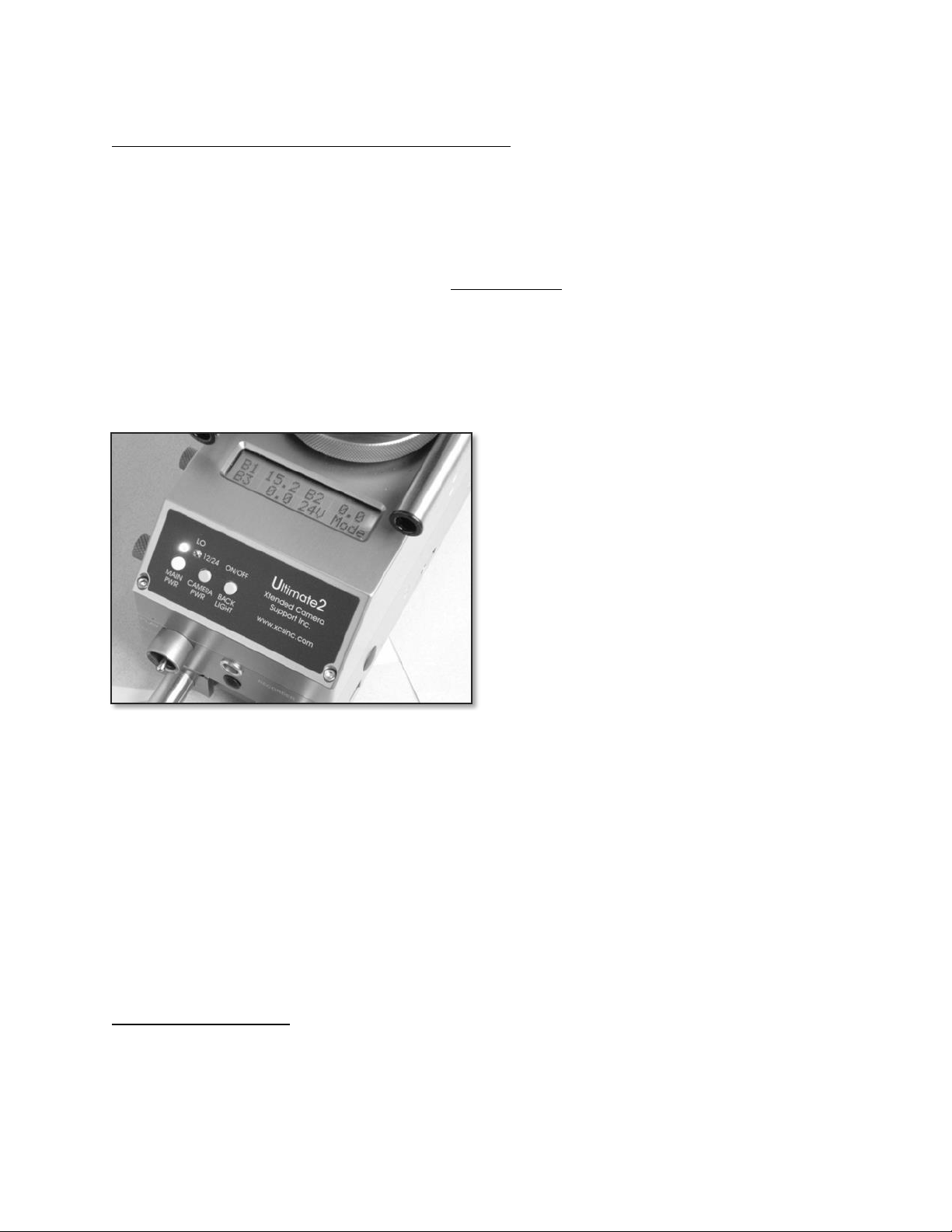
Getting Started with the Ultimate 2’s (U2) basic functions.
This system is designed to run both 12/24 volt camera systems and their accessories.
The owner can use any type of battery chemistry in any combination.
The lower electronics housing will accept up to three 14.4 volt battery packs or up to two 14.4 battery
packs and one 24 Vdc battery pack at the same time.
The sled can deliver 14.4 volts when using 1, 2,or 3, 14.4 volt batteries in 12 volt mode
The sled can provide both 14.4 and 28.8 volts when using two or more 14.4 volt batteries in 24 volt
mode. In 24 volt mode a 14.4 battery must be on battery plate # 3 and 1 or 2.
The sled can provide both 14.4 and 28.8 volts when using one or more 14.4 volt batteries and one 24 volt
battery.
All the system 12 volt outputs and all 24 volt outputs are common. One of the unique design features is
that it does not provide an isolated 14.4 volt power source.
Backlight LCD screen- The LCD displays current individual voltage battery status in 12 volt mode,
combined voltage of battery 3 in 24 volt mode, sled MODE and any text warning indicators.
MAIN PWR- Pushbutton turns the system
on/off. There is an amber LED pwr on indicator.
When turning OFF the power button must be
held down for at least 1 second.
LO battery indicator- Amber LED blinks when
the voltage drops below the user selectable
voltages. Factory preset for the warning
indicator as follows:
12 volt mode- Indicator blinks at 13.4 volts
24 volt mode- Indicator blinks at 24.2 volts
In 12 volt mode the 8 selectable settings are:
12.4, 12.6, 12.8, 13.0, 13.2, 13.4,13.6,13.8
volts
In 24 volt mode the user selectable settings
are: 23.0, 23.2, 23.4, 23.6, 23.8, 24.2, 24.4,
24.8 volts
User has two different 8 position rotary switches labeled SW1 (12 volt mode) SW2 (24 volt mode)
They are located inside the electronics housing and can be accessed by removing the 6 screws holding
the housing cover together.
12/24 Camera Pwr button- Allows the operator to select the power Mode the system will be running at.
12V Mode for 12 volt camera systems and accessories.
24V Mode for 24 volt camera systems and accessories, while still delivering 14.4 volts to all 14.4 volt
output connectors. To achieve 24 volts when using 14.4 batteries you need to have at least two battery
packs and one pack has to be on battery plate #3. Or you are using a 24 volt battery on plate #3.
ON/OFF BACK LIGHT button- Turns the LCD screen backlight on/off.
RECORD/PLAYBACK toggle switch- Directs the video signal input to the on board recorder in record
mode or to the 8 pin Lemo connector’s pin 8 for video playback through the LEH.
Connectors on the LEH.
These are the standard connectors and connections. Options available.
1B 308- Provides 14.4 battery voltage, video signal out 1V Peak-Peak from top stage. Also video
playback on pin 8 from the operators record deck.
0S 304- Provides 14.4 battery voltage, video signal out 1V Peak-Peak from top stage for video
transmitter.
8
Page 11
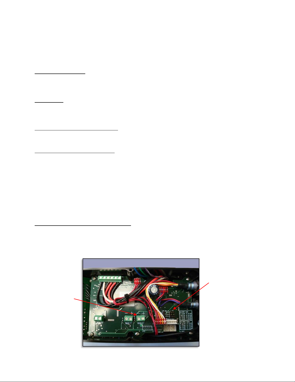
Removable jumpers are used
to set voltages for
RECORDER’s voltage output
Three battery
terminal blocks
BNC- Standard configuration provides one HDSDI loop through from top stage up to two available.
0B 306- Recorder power (user selectable) 4.5, 7.2, 9, 14.4 volts output and video out to recorder. Video
input to monitor on channel two. Removed but can be added
Rear Battery Housing
The rear battery housing can be moved in and out by loosening the two 10-32 SHCS. There are safety
stops on the ends so the housing will not slide off the rails. Over 4” of travel, increases your panning
inertia
Trim Knobs
The LEH comes set up with trim knobs on one side, they can be transferred to the other side of the sled
by loosening the set screw and spinning off the knobs. The left-right drive shaft must be removed and
reassembled on the opposite side. See “Swapping the inching knobs”
Programmable Digital Level Placement
There are two 4-40 drilled and tapped holes on each side of the LEH. These holes are aligned with the
XCS PDL housing. The screws should not protrude into the LEH housing any longer than .1875”.
On Screen (LCD) Text Messages
Upon power up, the sled’s serial number #0000xxx and the software revision level are displayed rev.2.0
Listed here are on screen text messages and causes for the error message.
BATT 1 CANNOT BE 24 VOLTS- 24 volt battery connected to wrong battery plate, B3 only.
BATT 2 CANNOT BE 24 VOLTS- 24 volt battery connected to wrong battery plate, B3 only.
Above two messages are each shown for a few seconds followed by a shutdown of the sled.
24V Over Current Cycle Power- Over current draw on the system or dead short or more than 36 volt
input. Turn off power, remove issue, and turn back on.
12V Over Current Cycle Power- Over current draw on the system or dead short or more than 18 volt
input. Turn off power, remove issue, and turn back on.
LEH internal user selectable adjustments
To access the internal adjustments inside the LEH you first should remove it from the Center
post. Remove the six 3/32” hex head screws holding the housing together. Lift up a few inches and turn it
over. There will be 6 to 8 wires and 1 or 2 connectors depending on your options connecting the top half
to bottom half. You now have access to make the following choice of adjustments.
9
Page 12
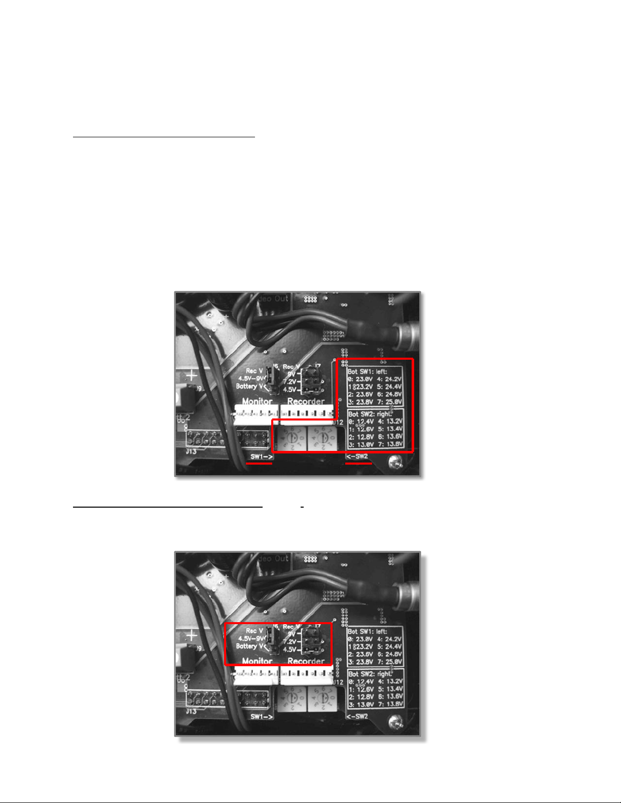
Set the 12 and 24 volt low battery indicators SW1 & SW2
10
Move the jumpers to adjust the RECORD deck selectable power options
Move the battery plate designation order from standard wiring B1, B2, B3.
Setting the Low Battery Indicators
Factory preset: SW1- 24.2 volts, SW2- 13.4 volts
When I set my low battery indicator I keep a few things in mind.
The type of batteries I most commonly use
The length of time I want to keep the system running after the indicator turns on.
Because battery types and sizes may vary for each operator, we allow you to simply adjust the LO battery
indicator to fit your needs. There are two different settings - one for 12 volt camera systems SW2 and one
for 24 volt systems SW1.
To set each LO battery indicator you simply need to turn the 8 position rotary switch label 0-8 that
corresponds to a specific voltage. There are two rotary switches inside the housing and a voltage value
key that shows the rotary switch number and the voltage value it corresponds to (photo below).
Adjusting the RECORDER Voltage Output. 0B 306 Connector no longer installed.
Two jumpers below allow selection of 4.5V, 7.2V, 9V, or battery voltage for the recorder. To select 4.5V 9V, the jumper J6 is placed on the top two pins and the voltage selected on J7. To use battery voltage for
the recorder, the J6 jumper is placed over the bottom two pins and the right jumper block is ignored.
Page 13
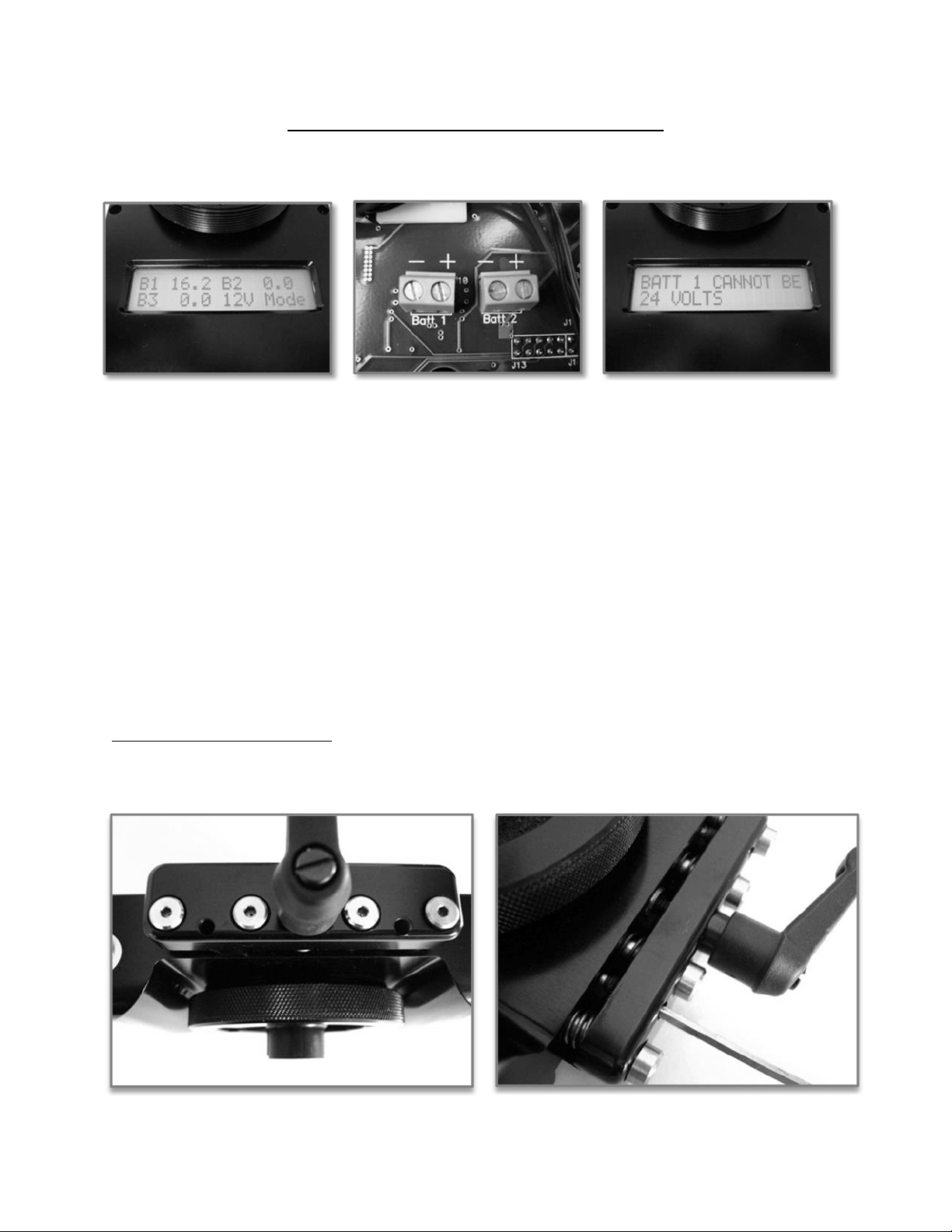
Adjusting LCD Battery Display Order B1, B2 & B3
The LCD displays output voltages for each battery on each battery plate. Labeled simply B1, B2 & B3.
The battery plate itself does not designate the order in which the batteries are displayed
B1, 2, or 3. The three terminal blocks on the circuit board labeled Batt 1, Batt 2 & Batt 3 that the battery
plates are attached to determines which battery plate is labeled B1, B2 & B3 on the LCD. You can
change this designation by simply changing the order of the wires from the battery plate to which terminal
block. (See photo above)
This is may be important for operators who wish to take advantage of just one of unique sled designs
allowing it to accept and run a single 24 Vdc battery in conjunction with a 12 Vdc battery. Battery terminal
block 3 is the only terminal block that can accept a 12 or 24 volt battery. Battery terminal block 1 & 2 will
not allow the system to be powered by a 24 Vdc battery. Instead the LCD will display a text message
telling you that “B1 or B2 CANNOT BE 24 VOLTS” (See photo above) and turn the sled off.
Battery terminal block 1 can accept up to 18 Vdc.
Battery terminal block 2 can accept up to 18 Vdc
Battery terminal block 3 can accept both 12 or 24 volt batteries up to 36 Vdc
When running the sled with a 24 volt battery block only 24 volt connectors will have power. If you are
running 12 Vdc accessories you will need to add a 12 Vdc battery to one of the other battery plates.
Adjusting the Dovetail Clamp
If you find that your camera plate is sliding or the clamp is hanging up on the four shoulder bolts, the
clamp’s two brass tipped set screws are out of adjustment and need to be reset.
11
Page 14
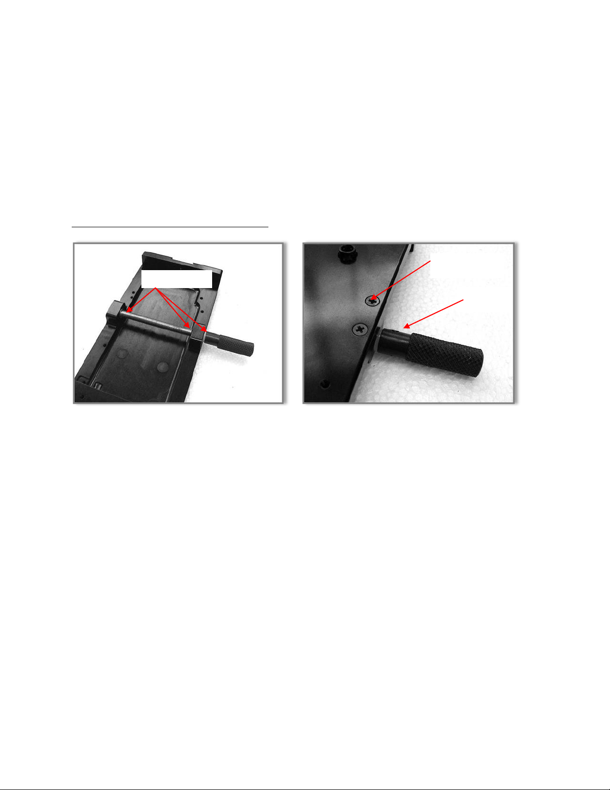
Locate the two set screws on the side of the dovetail clamp, back them out 2 turns.
3 shaft spacers
Two removable
Phillips screws
Set screw
With a dovetail plate in the platform, snug up the clamp using the Kipp handle. Do not over
tighten it as if you are clamping it down, just snug so it takes a bit of end pressure to slide the
camera plate in the camera platform.
Flip the UCP over (leaving the camera dovetail plate snug) and turn the two set screws in equally.
Snug up both brass tipped set screws. I measure the distance of the gap with a caliper and keep
it close. You might want to put a thread locker on these set screws to keep them from moving.
Tighten up the Kipp handle with normal finger pressure and make sure that the camera plate
does not slide. If it does slide, loosen the Kipp handle again back out the set screws a very small
amount - 1/10th of a turn at a time each set screw, remeasure the gap, tighten the Kipp handle.
Repeat if necessary. I set the gap +/- 0.001” measured at each set screw when manufactured.
Swapping the inching Knobs side to side
The first photo is a cutaway of the LEH and shows you how the shaft sits. It does screw through a plastic
nut that means you will have to turn out the drive shaft and turn it back in.
There are three spacers on the drive shaft. One on the inside end of the drive shaft, and one under the
knurled inching knob.
Remove the LEH from the post.
.050” hex head wrench removes the set screw on the knurled knob, spin the knob off the shaft.
Remove the two Phillips head screws on the bottom as shown.
Spin out the drive shaft, flip it around and spin it back it.
When you have the drive shaft almost all the way in, place spacer on shaft end, insert it into end
cap.
Add spacer on other shaft end and add the removable end cap.
Screw in two Phillips head screws.
The Fore and Aft knob is very simple.
Loosen the set screw, spin out the inching knob.
Remove the plastic cap on opposite side and place the knob on the shaft, tighten set screws.
Replace plastic cover on open hole.
12
 Loading...