

Page 1

XCOM 760
VHF Transceiver
Installation and Users Manual
Page 2

Release 1.2 © XCOM Avionics 2004 www.xcom760.com Page 2
Page 3

Table of Contents
Introduction...................................................................................................4
Features Overview..........................................................................................4
Manual Release Information.............................................................................5
Contents .......................................................................................................6
Users Manual .................................................................................................6
Warranty Card ...............................................................................................6
Description ....................................................................................................6
Front Panel Controls and Switches ....................................................................7
LCD Display ...................................................................................................8
TX Transmit Icon ......................................................................................8
RX Receive Icon........................................................................................8
DUAL WATCH ...........................................................................................8
LOW BATT ...............................................................................................8
MEM........................................................................................................8
Top Line ..................................................................................................8
Bottom line ..............................................................................................8
Bar Graph ................................................................................................8
XCOM Installation...........................................................................................9
Wiring Harness ..............................................................................................9
Aerials ..........................................................................................................9
Radio Frequency Hazard Information ...........................................................9
Operating your XCOM Transceiver ..................................................................10
On ........................................................................................................10
MODE....................................................................................................10
MEM......................................................................................................10
Dual......................................................................................................11
Flip Flop button Ú ...................................................................................11
Memory Programming...................................................................................12
Introduction ...........................................................................................12
Operation ..............................................................................................12
Setup Options ..............................................................................................13
Introduction ...........................................................................................13
Operation ..............................................................................................13
DUAL - MODE - ON .................................................................................13
Aerial Information ........................................................................................14
Wiring Diagram – Typical Installation ..............................................................16
XCOM VHF760 Transceiver Specifications - Subject to Change ...........................17
Drilling Template ..........................................................................................18
Warranty Card .............................................................................................18
Notes..........................................................................................................19
Release 1.2 © XCOM Avionics 2004 www.xcom760.com Page 3
Page 4

Introduction
Thank you for purchasing the XCOM 760 VHF Transceiver, this manual describes
the operation and installation of this product, should you have any questions that
are not answered in this manual please contact XCOM Avionics in Australia on
+61 7 5568 7770 or by email to [email protected]
The XCOM 760 VHF Transceiver is the first of several innovative avionics products
to be released by XCOM Avionics. Based on the very successful Microair and Becker
ranges, the XCOM 760 offers many advanced features previously only available in
the more expensive brands.
Designed from the ground up, the XCOM 760 offers superior performance under the
demanding and noisy conditions experienced in many amateur built aircraft. With
low power consumption, this radio is ideally suited to use in gliders, homebuilts and
ultralights.
A full 6 watt carrier output ensures that you will be heard above the general chatter
in busy airspace and the VOX intercom with muting music input will enhance your
enjoyment of the flight. With expanded receive range up to 163 MHz, the XCOM
760 provides NOAA Weather reception ensuring that you are always aware of
impending weather conditions (NOAA Weather only operates in the USA) and has
an optional MARS/CAP capability.
Additional safety enhancements such as dual watch allow the pilot to listen to the
standby frequency while still monitoring the primary frequency. The XCOM 760 also
has 99 memory channels, large volume and channel selector knobs and well spaced
buttons. This radio is extremely easy to operate even when wearing flight gloves
and you can even check the condition of your battery with the built in voltage
monitor. Even at voltages as low as 10 volts, the XCOM 760 is capable of delivering
2 watts of carrier with full modulation.
Software update capability and Internet downloads mean that you are always
provided with the latest features.
Features Overview
• Digital volume and squelch controls from front panel
• Digital volume and VOX intercom controls from front panel (same Volume
Squelch control, but activated by mode button when required).
• 2 place voice activated intercom, with pilot over ride and passenger isolate
(pax can listen to CD music whilst pilot listens to com). CD music has auto
fade, turns off if comm is receiving or reduces in volume if pilot or pax talk.
• Extra audio input (second com, VOR or GPS alert)
• Remote toggle (toggle active or standby via a push button on the stick, or
scroll memory channels)
Release 1.2 © XCOM Avionics 2004 www.xcom760.com Page 4
Page 5

• TX timeout (stuck Mike) which times out after 45 seconds, re-enable by
releasing PTT.
• 99 channels of user defined memory channels.
• 10 pre-programmed NOAA weather channels (suitable for USA only)
• Dual Watch - allows monitoring of the active and standby frequency, active
has priority.
• User enabled wide receive mode - allows monitoring of frequencies between
137 and 163 MHz, in 25 kHz steps. These can be stored in memory channels.
• RS 232 interface, allows upgrading of firmware by internet or CD-ROM. Allows
interfacing of radio to multifunction displays (MFD's) or remote computer.
• Low battery alert, user selects level to alert for under voltage (default is 10.5
Vdc)
• Optional MARS / CAP capability (special order)
XCOM Avionics reserves the right to update this manual as product enhancements
are made throughout the life of this product. The actual release number of this
manual is printed on the bottom of the pages for easy reference and the latest
version can always be downloadable from the XCOM web site.
Manual Release Information
Release Date Changes
1.0 Jan 04 Original draft of document
1.1 May 04 Release of manual to public
1.2 July 04 Addition of aerial safety information re: FCC Request
Release 1.2 © XCOM Avionics 2004 www.xcom760.com Page 5
Page 6

Contents
The XCOM 760 is packed within a cardboard box for protection; the transceiver
itself is wrapped in an anti-static bag for electrical protection. The boxed contents
are….
• One XCOM 760 VHF transceiver
• User manual
• DB15 solder plug and plastic back shell
• Optional: If you purchased the optional wiring harness it will be included in
this package with installation instructions.
Users Manual
Please read and understand this manual BEFORE attempting to install and operate
this transceiver, the XCOM VHF 760 has many advanced features which if not
properly understood could cause improper operation of this product.
Warranty Card
Included in the rear of this manual is the warranty card, please fill out your details
and return to the manufacturers address provided, please don’t return the card to
your dealer. Alternatively you may fill in the warranty details online through the
website http://www.xcom760.com
- select warranty registration
Description
The XCOM VHF 760 Transceiver has a 2 ¼ inch (57mm) face for fitting in a normal
aircraft small instrument hole. The case is 129mm long, 61mm wide and 61mm
high. The unit is secured to the aircraft dashboard by 4 screws and is self
supporting and requires no additional supports, trays or brackets.
Release 1.2 © XCOM Avionics 2004 www.xcom760.com Page 6
Page 7
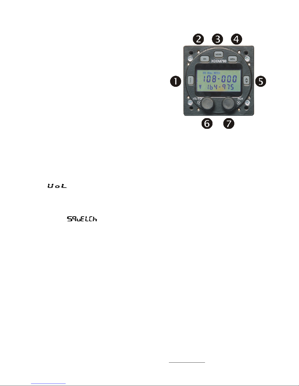
Front Panel Controls and Switches
n DUAL - Press once to activate dual receive
capability, Dual Watch icon will be illuminated
in the LCD Screen, press again to de activate
ON - Press for 1 second to turn the
o
transceiver ON, depress for 2 seconds to turn
OFF
MODE - Activates the various different
p
modes and displays
q MEM - Press once to access the 99 memory
locations. Press again to access the NOAA
weather channels (If enabled in setup)
r Flip Flop (Transfer) Press to transfer the
bottom line to the top and visa versa. The top
frequency is the active transmit channel
(Transmit does not apply to weather and
extended receive channels)
s VOL/SQH - Default is volume, simply
rotate the control left (volume goes down) or
right (volume goes up). The level is displayed
in the BAR graph on the LCD and well as the
word
To activate the squelch, press the knob in
once, rotate left to decrease and open, rotate
right to increase and close, the level is
indicated by the bar graph on the LCD as well
as the word
squelch will also illuminate the RX icon on the
LCD. After 3 seconds of no activity the control
reverts back to volume. These controls also
adjust the intercom squelch and volume.
. Note that a fully open
t F/CH The default is MHz, rotating left
decreases the MHz frequency and rotating right
increases. To activate the KHz, press the
control in once, rotating left decreases the KHz
whilst rotating right increases. After 3 seconds
of inactivity the control will revert back to KHz
Release 1.2 © XCOM Avionics 2004 www.xcom760.com Page 7
Page 8
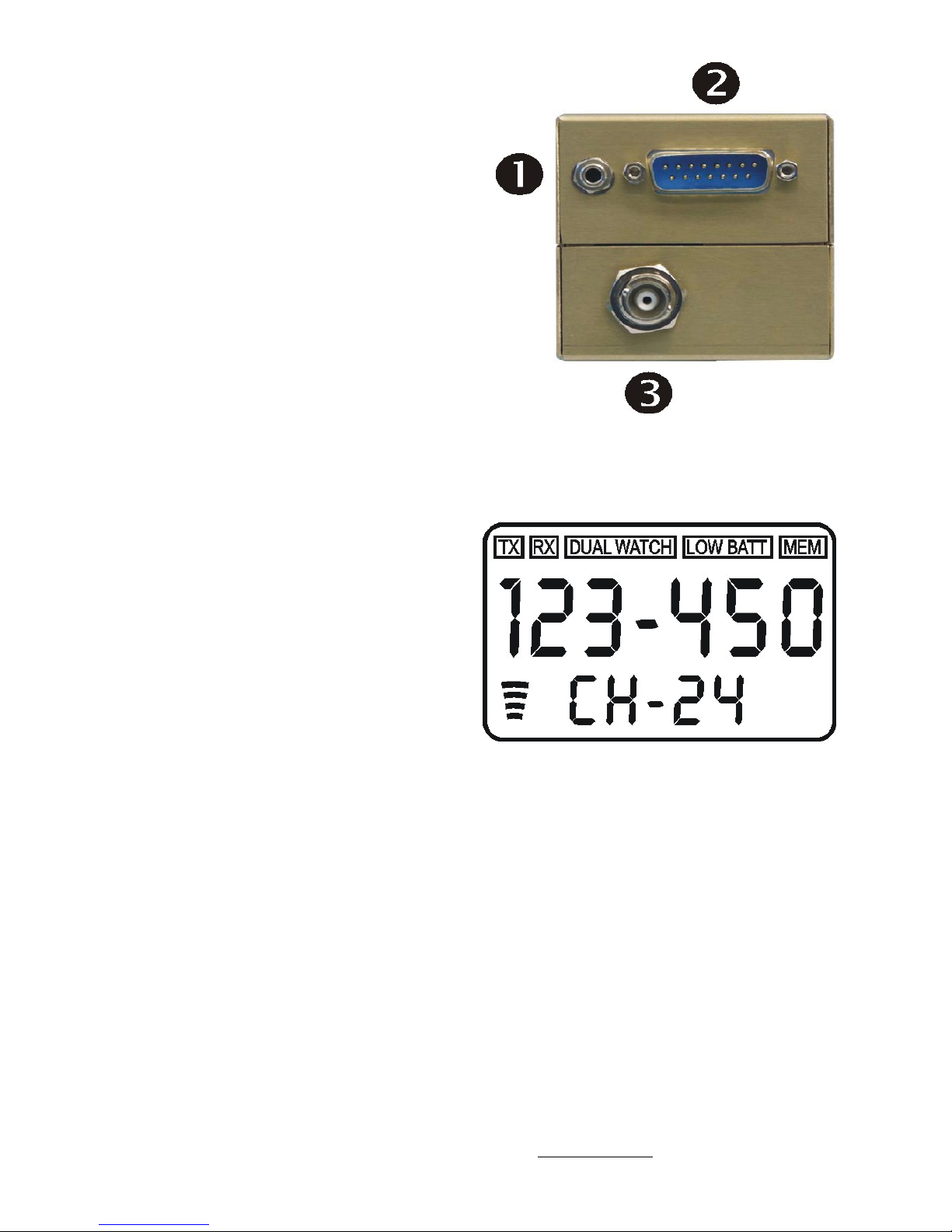
The rear of the radio has
n RS232 Port for programming and
additional external control over the radio
o
DB15 pin plug for connection of the
wiring harness
p
BNC fitting for the aerial connection
LCD Display
TX Transmit Icon, blinks when
Transmission is over 30 seconds, Icon
resets after 45 seconds (stuck Mike) or
PTT is released
RX Receive Icon, lights up when a
signal is being received or squelch is
opened
DUAL WATCH Lights up when the dual
watch button is depressed and activated
LOW BATT Blinks when power goes
above or below the pre set limits.
MEM Lights up when in memory mode
Top Line Displays the active channel in
the larger text
Bottom line Displays the standby
channel, memory number and other
status text.
Bar Graph Received volume and
squelch levels as well as intercom
volume and squelch levels.
Release 1.2 © XCOM Avionics 2004 www.xcom760.com Page 8
Page 9

XCOM Installation
The XCOM 760 VHF Transceiver installation is straight forward and requires no
special skills, the wiring harness does require someone with a reasonable
knowledge of wiring and the proper equipment for the installation, it’s our
recommendation to purchase the pre-made wiring harness or have a local avionics
shop do the job for you.
Position the supplied template on your dash and when happy with the location drill
through the template in the marked positions, the main hole is 2 ¼ inches and the
4 securing holes are drilled 7/32 inch or (5.5mm), make sure the controls for the
radio are within sight and reach of the pilot when sitting and secured in the pilots
seat.
Please check behind your dash for other instruments and wiring which may be
damaged during drilling.
Bring the radio in from behind your dash and secure in place with the 4 mounting
screws (supplied) if you ever need replacement screws they are 6/32 UNC by 1/2
inch long.
Wiring Harness
The wiring harness is the one task that causes our customers the greatest
frustration when fitting a radio; unless you have experience in this area we would
strongly recommend getting a pre-made harness or having an avionics shop do the
harness for you.
If you decide to manufacture your own harness please refer to the web site for
techniques and wiring diagrams for ease of manufacture.
Some basic requirements are to use aircraft quality Tefzel wire, the power supply
should be 18 gauge wire and the other wires 22 gauge, the aerial wire should be
made from 50 ohm coaxial cable. All toggle switches and PTT switches should be
good quality and the headset and mike jacks should be aviation quality, if you need
jacks these can be purchased from our web site.
Aerials
Correct operation of the transceiver requires a properly installed aerial suitable for
the frequency range 118 to 137 MHz. On any new radio (or aerial) installation, the
VSWR of the aerial should be checked. The aerial VSWR should preferably be no
higher than 1.5:1. While no damage to the transceiver will occur with VSWR’s of
3:1, some degradation in performance must be expected. There is more
information on aerials in the rear of this manual and on our website.
Radio Frequency Hazard Information
Regulations require a safe working distance between the Pilot, Co-Pilot, Passengers
or the general public of at least 100 cm (27 inches) to the aerial location. If an
antenna gain of greater than 5.6 dBi is to be used the manufacturer should be
contacted in order that a safe distance can be determined.
Release 1.2 © XCOM Avionics 2004 www.xcom760.com Page 9
Page 10

Operating your XCOM Transceiver
On - To switch the unit on simply depress the ON button for one second. The
transceiver will switch on. To switch off hold the button in for 2 seconds, the
transceiver will switch OFF. The transceiver will start up in whatever mode it was
left in, e.g. if the unit was turned on by the ON button, but turned off via the
power, say an avionics switch, then when the power is restored it will turn on
automatically. If the unit was turned off using the ON button, and then power
removed, it will be off when power is re-applied.
MODE - This is the main menu button for selecting various user options and for
displaying the voltage. To activate the first option push the button once, at any
time you want to go back to the main receiving screen hit the Ú button, this acts as
a hotkey to return you back to the main screen, when back in the main screen it
reverts back to a flip flop function.
There are 5 options
IntVol Intercom Volume, rotating the VOL/SQH control will increase or
decrease the intercom volume. The bar graph will go up or down to
indicate level. Hit the Ú to return to the main screen or MODE to access
the next option.
IntSQH Intercom Squelch, rotating the VOL/SQH control will increase or
decrease the intercom squelch. The bar graph will go up or down to
indicate level. Hit the Ú to return to the main screen or MODE to access
the next option.
VoR On Receive VOR (Audio ONLY) this means the receive range includes 108
to 117.975 MHz. Push the F/CH knob to toggle the option between On &
Off. Rotating the F/CH knob clockwise accesses the General
Coverage option.
Gen On
General Coverage option is enabled. The receive range is now from
118.00 to 163 MHz or 108 to 163Mhz if the VOR option is also enabled.
The receive sensitivity reduces at the 150 MHz + end. Above 137 MHz
the mode changes to FM. This enables monitoring of the popular
Amateur 2 meter band and marine frequencies. Push the F/CH knob to
toggle the option between On & Off. Hit the Ú to return to the main
screen or MODE to access the next option. Rotating the F/CH knob
anti-clockwise will return to the VOR option screen.
VoLTS Shows the current voltage, rotating the F/CH up or down will show the
high volts set point and the low volts set point. Hit the Ú to select this
option and return to the main screen.
MEM - Press this button once to access the 99 memory channels. Note that if
nothing is programmed into the memory, the display remains unchanged. The
Release 1.2 © XCOM Avionics 2004 www.xcom760.com Page 10
Page 11

memory channels are displayed as channel number on the bottom line and
frequency on the top. Use the F/CH control to scroll through the memory channels.
Only channels that are programmed will be displayed. If you wish to load the
memory frequency to the main flip flop screen for either using later to transmit on,
or to dual monitor, simply press and hold in the Ú for 2 seconds, this will transfer
the currently displayed memory channel to the flip flop screen and return you to
the flip flop screen. If you press it only once (do not hold in for longer than a
second) the screen will revert back to the main screen (flip flop) with no memory
channel loaded.
Press the MEM button twice to access the NOAA weather channels, use the F/CH
control to scroll through the weather channels. Hit the Ú to select this option and
return to the main screen.
Dual - Press this button when in the main screen (flip flop). The DUAL WATCH icon
will be illuminated. Both the active and the standby frequencies are now being
monitored. The active is always considered the priority frequency and the standby
the secondary frequency. Whilst listening to the active frequency the transceiver
checks the standby 4 times a second for activity, if there is activity then it locks on
to the standby and stays there for the duration of the transmission on the standby
frequency unless there is a transmission on the active frequency. If there is a
transmission on the active frequency the transceiver will stay there only returning
to scanning on dual watch 5 seconds after voice transmission has ceased. If you
press the PTT button you will only transmit on the active frequency while in dual
watch, the dual watch feature will temporarily switch off for about 5 seconds when
you transmit expecting a reply to come back from another aircraft or ATC, if no
reply comes back then the transceiver will return to scanning again.
Note: When there is a station talking on the standby frequency a slight PIP PIP
sound may be heard, this is the scanning sound as the transceiver momentarily
checks the active frequency, this sound is normal in this mode.
If the active frequency is receiving the RX icon will be illuminated, and the –
between the MHz and KHz on the active frequency display will blink (top line
display), this indicates that the active is receiving. If the standby is receiving then
the RX icon will be illuminated and the – between the MHz and KHz will blink on the
standby frequency (bottom line display), this indicates that the standby frequency
is receiving.
Flip Flop button Ú - Pressing this in the main screen (flip flop screen) will transfer
the top line to the bottom, and the bottom to the top. When in MEM mode, pressing
and holding it down for 2 SECONDS will transfer the currently displayed MEM
channel to the standby screen in the main screen (flip flop screen). When in MEM
mode pressing it for 1 second will revert back to main screen. When in MODE
screens, hitting the button will either enter and return or just return back to the
main screen.
Release 1.2 © XCOM Avionics 2004 www.xcom760.com Page 11
Page 12
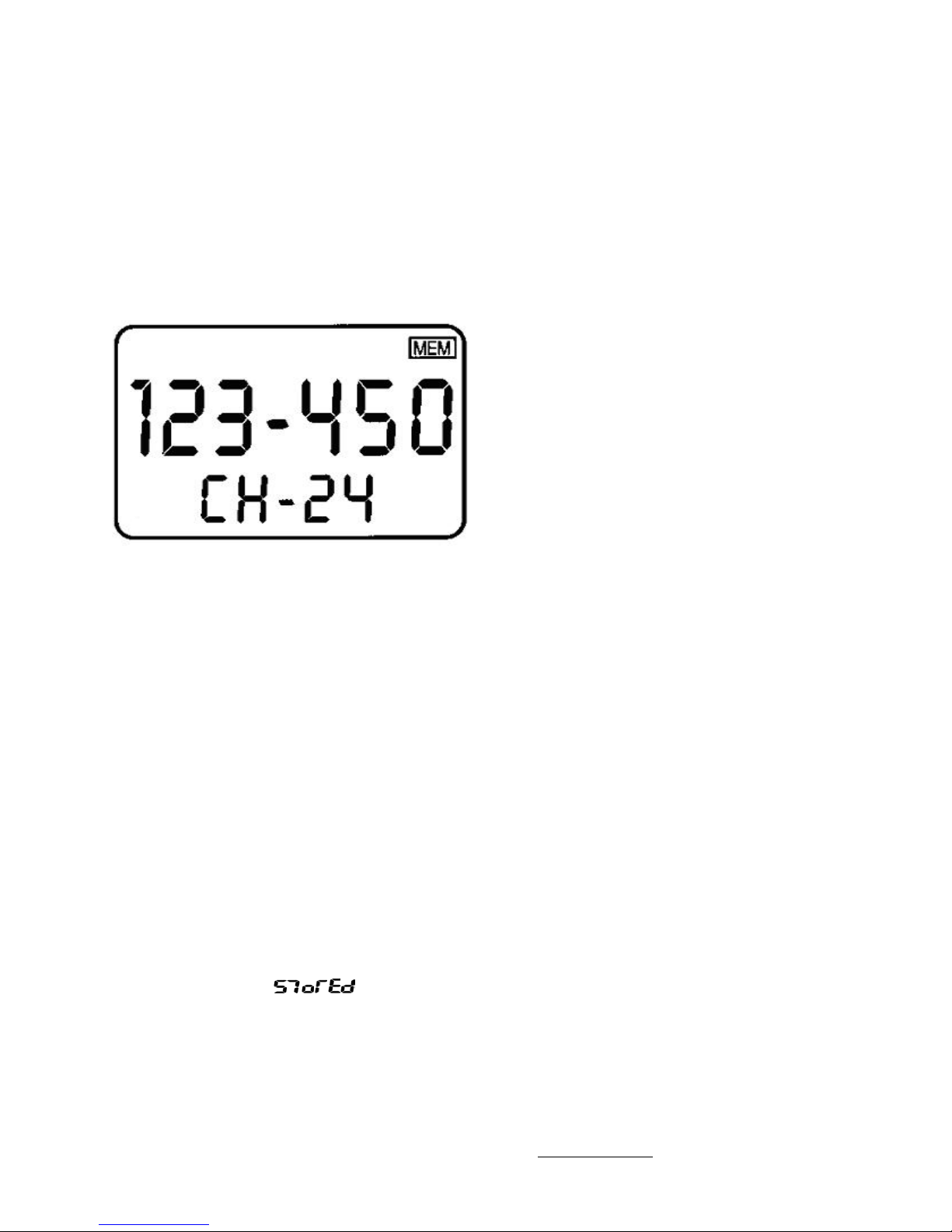
Memory Programming
Introduction - The Xcom760 has 99 user programmable memory channels, stored
in non-volatile memory. The memory channels can be programmed via the keypad
or via the RS 232 data link (using the serial port and windows based software). This
section deals with the keypad entry method, refer to the XCOM760.com website for
software downloads and interface details.
Operation - To enter the memory programming mode press and hold in for 3
seconds the MEM key. The MEM icon will blink during the programming procedure.
Note: blinking digits indicate current changeable value; e.g. blinking 123 indicates
that the MHz value can be changed.
The F/CH control allows scrolling, simply push it in to select and rotate the values,
the action for this moves clockwise, starting at the CH value, this selects the
channel number which is 0 to 99, press once to select the rotate value mode, by
turning right (up) or left (down) the channel number will change, make sure you
accidentally do not erase a channel that is already programmed (to check simply go
back to the main screen by hitting the Ú) and then enter the memory screen by
pressing the MEM button). Once you are happy with the Channel number press the
F/CH control in again, this will then select the MHz, press in again to change this
value. If the Vor or Gen options are enabled (see OPERATION, MODE for procedure)
then these receive only frequencies can be entered as well, if these options are
subsequently disabled, then the entered frequencies will still be in the memory
allocations, as these are independent of any other mode selections. Press in the
F/CH again and this will then move you on to the KHz display, press the F/CH to
activate scroll and now rotate the F/CH to select the desired KHz frequency. If you
press the F/CH again it will bring you back to the CH display. When you are
satisfied that the correct channel is programmed press and hold the MEM in for 2
seconds. The word
channels simply repeat the procedure, when you wish to return to the main screen
simply press the Ú. If you want to clear the memory area then at start up press
both the ON and MEM buttons together, this will erase the FULL 99 channel
allocations, irrespective of how many are programmed. The above programming
and erasing feature can also be done via the RS 232 port, using the free XCOM760
utility from the xcom760.com website.
will be displayed for 3 seconds. To program the full 99
Release 1.2 © XCOM Avionics 2004 www.xcom760.com Page 12
Page 13
Setup Options
Introduction
The setup screens are not programmable during normal use, as these options effect
how the transceiver will display screens, or operate in general. The following
procedure relates to programming these options and care should be taken. DO NOT
adjust the Microphone gain control unless you are confident to, read the
instructions and if in doubt have an avionics technician do the adjustment for you.
The setup parameters can also be changed via the RS-232 port using the windows
based SETUP utility, which can be downloaded at xcom760.com
Operation
The access the setup screen, press and hold at startup the following buttons:
DUAL - MODE - ON
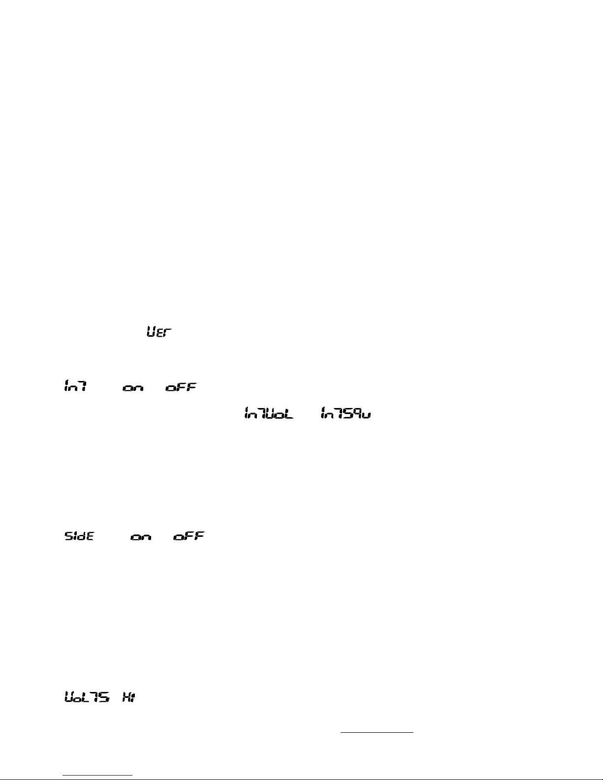
The setup screen will appear; first it will display the current version number for 5
seconds, e.g.
The screen will then display the following setup options:
option or This selects the intercom to be on, or off (default is ON). In
Note: Selecting the intercom to OFF aids in current
option or This selects the Microphone sidetone ON or OFF
Note: Selecting the SIDETONE to OFF aids in current
- This sets the HIGH point trip for the battery alert, Rotate
Release 1.2 © XCOM Avionics 2004 www.xcom760.com Page 13
1-01
the ON mode, the intercom is enabled in the transceiver
and the
and appear in the MODE screen.
To set on or off simply rotate the F/CH control. Press the
F/CH to go on to the next option or Ú to return to the main
screen, the new values will be stored.
consumption savings, important for battery powered
applications like gliding.
(Default is ON). Selecting ON enables the sidetone during
transmission, which can only be heard in the headsets.
Selecting OFF removes the sidetone. To set on or off simply
rotate the F/CH control. Press the F/CH to go on to the next
option or Ú to return to the main screen, the new values
will be stored.
consumption savings, important for battery powered
applications like gliding.
the F/CH control to set the upper limit. The default is 15
Page 14

volts. Press the F/CH to go on to the next option or Ú to
return to the main screen, the new values will be stored.
- This sets the LOW point trip for the battery alert, rotate the
F/CH control to set the lower limit. The default is 11.5 volts.
Press the F/CH to go on to the next option or Ú to return to
the main screen, the new values will be stored.
Option ## This sets the stuck Mike, or Transmitter ON timer, the value
range is 10 to 90. The timer is normally set for 45 seconds,
and has a maximum timeout of 90 seconds. To set a value
simply rotate the F/CH control. Press the F/CH to go on to
the next option or Ú to return to the main screen, the new
values will be stored.
Option ## This adjusts the microphone gain, and is provided to
accommodate different brands of microphone. The gain
control has a limited range in order to prevent users
inadvertently making the transceiver inoperable by
reducing the microphone gain to zero. Since the gain
control is before the modulation limiting circuitry it is not
possible to cause over modulation by increasing the gain
control to the maximum available in this mode. NOTE – the
factory default settings should be fine, we only recommend
using this option as a last resort. . Press the F/CH to go on
to the next option or Ú to return to the main screen, the
new values will be stored.
Aerial Information
The XCOM 760 Transceiver is a state-of-the-art product and requires a quality and
matching aerial to provide owners with the best possible performance, clarity and
range. Some of the most important considerations are the location of the aerial and
the proper installation and cabling to the radio.
The most suitable location for the aerial is generally on top of the aircraft, in a
location which can provide the best unobstructed line-of-sight view of the
surrounding areas, preferably keep the aerial at least 1 meter away from other
aerials or the rudder.
Earthing the aerial to the aircraft ground is very important, if this is not done
properly performance will be well under your expectations and the actual
transmission patterns may be uneven and the voice possibly unreadable. On metal
aircraft with certain aerials it is necessary to remove the paint from the inner
surface to provide a good metal-to-metal contact of the aerial with the aircrafts
outer skin, on composite aircraft it is usually necessary to install a ground plane.
The ground plane on a composite aircraft should be at least 500mm diameter or
larger, the best performance will be gained with the biggest ground plane size. In
many composite aircraft it is possible to epoxy or RTV (silicone) a thin piece of
Release 1.2 © XCOM Avionics 2004 www.xcom760.com Page 14
Page 15

aluminum sheet inside the structure, I have also seen the use of self adhesive foil
but I have found this usually breaks down due to movement of the aerial base and
it eventually becomes useless.
There are also several ground plane independent aerials available and some we
have trialed with good results but it is my belief a solid aluminum ground plane is
the best. To prevent corrosion and water entering your aircraft always use a sealant
like silicone or RTV approved for the structure of your aircraft around the aerials
base.
The final choice now comes down to the aerial construction, most VHF aerials used
on sport aircraft are ¼ wave whip type aerials made from either metal or fiberglass,
the better aerials sometimes costing 5 times more than the cheaper ones with only
a fractional increase in performance. Basically I believe the more you spend the
better the aerial and the better range you could expect from the transmission.
Most aerials sold today are already ‘tuned’ for the VHF range with frequency 127.00
being about the norm. After installation of your radio and aerial it is recommended
a SWR test be performed at 127.00 MHz and the aerial tuned to try and get the
SWR reading as low as possible, ideally you should try for a reading around 1.5:1
but up to 3:1 is still considered acceptable. Try to keep the aerial cable as short as
possible and don’t wrap it up with other cables like those from the strobes or
battery as interference will be expected and never coil excess cable, always cut the
aerial cable to the correct length.
Release 1.2 © XCOM Avionics 2004 www.xcom760.com Page 15
Page 16
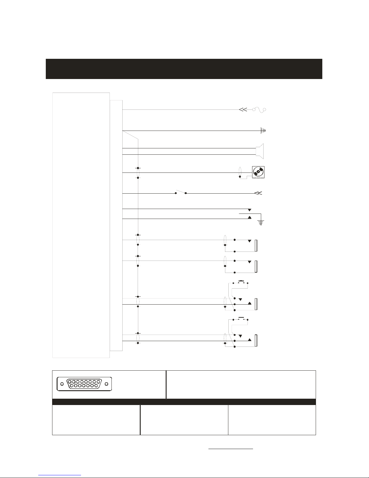
Wiring Diagram – Typical Installation
XCOM VHF76 0 TRA NSCEIVER W IRI NG DIAGRAM
Ver s i on 1 - Iss u ed Ju ly 20 0 4 Co py r ig ht XCOM A v ioni cs w w w.x com7 6 0.c o m
All wires 22 AWG except powe r and ground
Pin s
+13.8 V
+
910
Wire 18 AWG
3A Fuse mus t be fitted
Ground
Spe aker
Mu s i c I npu t
Backlight
Intercom ON/Off
Pilot Headphon es
Co-Pilot Headphones
Pilot PTT
Pilot Mic
12
15
14
13
4
2
8
11
Wire 18 AWG
+
-
To pa n e l di m me r
ON
5
Isolate
PTT Button
16V Maximum
Centre off switch
Pilo t Headphon es
Co -P ilot Headp hones
7
1
Pilot Mic
Co-Pilot PTT
Co -P il o t M i c
1 2 3 4 5 6 7 8
9 10 11 12 1 3 14 15
Pin 1
Elec tret, Amplified Dynamic Pilot Mike
Pin 2
Musi c Aux Audio Input
Pin 3
Elec tret, Amplified Dynamic Co Pilot Mike
Pin 4
Speaker Output 8-16 Ohms
Pin 5
Intercom ON ground to operate
Release 1.2 © XCOM Avionics 2004 www.xcom760.com Page 16
6
3
DB15 FEMALE plug viewed
from the rear (wire) side
PTT Button
When using Electret or Ampli field Dynamics you must use individu al inputs (1 and 3).
Notes:
Do not parallel more than one per input.
Speaker now has a s eparate n egative le ad - do not ground the speaker as da mage wi ll result in
the radio spe aker amplifier!
XCOM 760 VHF Transceiver Pin Details
Pin 6
PTT Co Pilot
Pin 7
PTT Pilot
Pin 8
LED Backlight +12V
Pin 9
Positive 12 Volts
Pin 10
Positive 12 Volts
Pilot Isolate
Pin 11
Pin 12
Negative Ground
Pin 13
Hea dphone Outpu t Co Pilot
Pin 14
Hea dphone Outpu t Pilot
Speaker Output 8-16 Ohms
Pin 15
Co -P ilo t Mic
Page 17

XCOM VHF760 Transceiver Specifications - Subject to Change
• Approvals: FCC, ACA Pending
• Tested to TSO C37d and C38d, environmental DO-160D
• Receiver Class D
• Transmitter Class 4
• Note: Transceiver was designed to these specifications and meets and
complies with these, but has not yet been submitted for official TSO testing.
• 118.000 to 136.975 MHz, 760 channels transmit and receive (AM)
• 137 to 163 MHz general coverage receive including NOAA weather channels.
user enabled, default is OFF)
• 108 to 117.975 VOR Receive audio ONLY (No Nav)
• 140 to 144.00 MHz MARS CAP capable (on request)
• QUASI Alphanumeric Display - 2 line LCD
• Backlighting - Display and keypads, external lighting control volts
• Memories - 99 user definable memories, non volatile (no battery required)
• Sensitivity - AM – better than 12db for 1.2uv (30% modulation at 1khz audio)
• FM – Better than 12db for .5 uV (5kHz deviation at 1Kz audio)
• Transmit Power – 6 watts carrier minimum into 50 ohms
• 2 watts emergency operation (10 volts input)
• Transmit timeout (stuck Mike) 45 seconds default
• Microphones - Electret or Dynamic (user selectable)
• Intercom: 2 place voice activated with muting CD music input
• Auxiliary input: 1 V. P to P
• Input voltage 13.8Vdc (9 to 16 Vdc Receive, 10.0 volts transmit, reduced
output)
• Current consumption - < 100ma Receive (muted) no intercom on.
• <2.5 amps transmit
• Voltage alert - Low battery indication, user definable (default 11.5 Vdc)
• Temperature range - minus 20 to +55 degrees C (emergency -40 to + 85
degrees C)
• RS232 programming port for downloading memory channels and operating
parameters etc from a PC, Also used for software upgrades
• Optional remote control module allows stick operated frequency selection,
dual watch and memory channel operation.
Release 1.2 © XCOM Avionics 2004 www.xcom760.com Page 17
Page 18
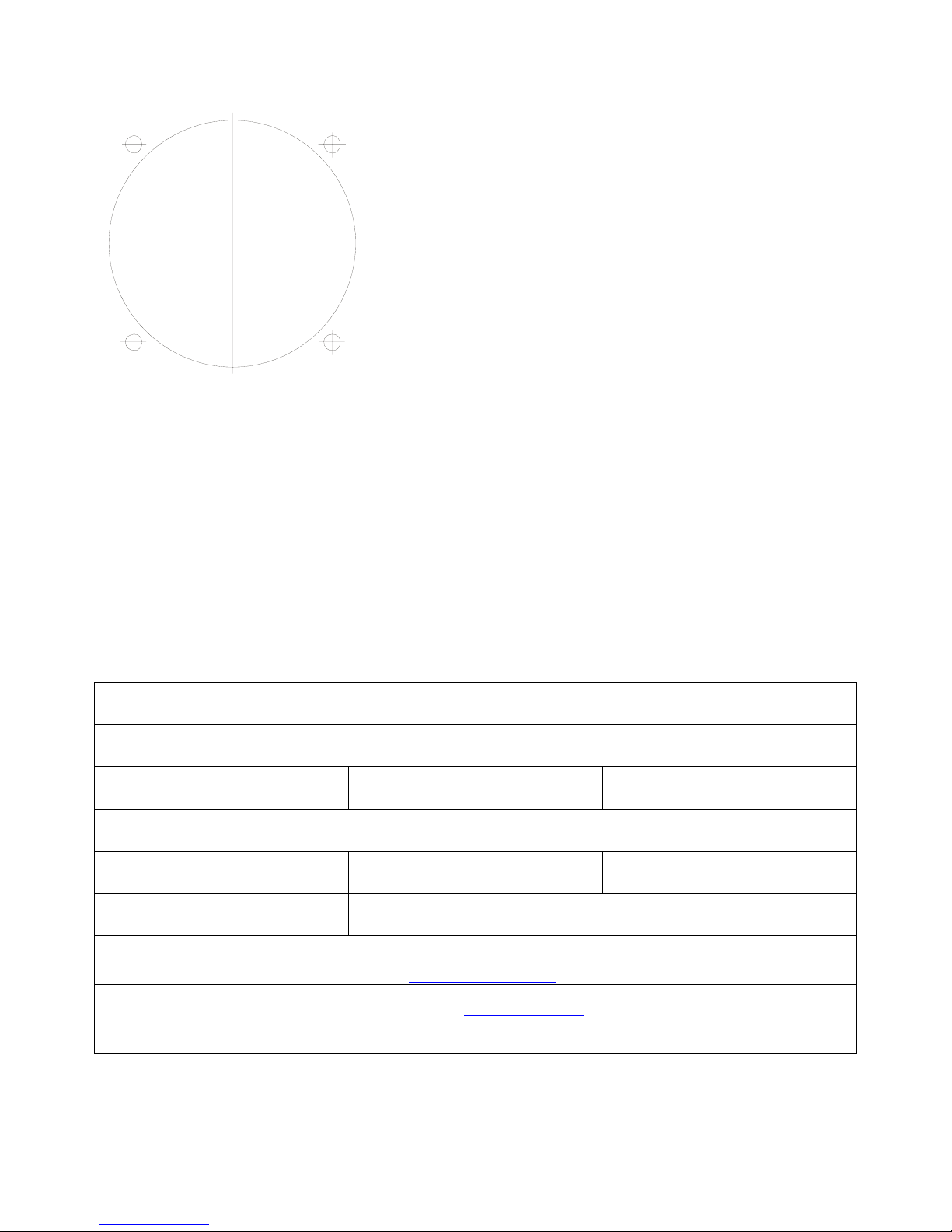
Drilling Template
NOTE: Please check this template has not
changed size during printing !
Each radio shipped is supplied with a removable
template sticker which can be used for the
XCOM’s installation.
IF YOU HAVE THIS DIAGRAM IN A SMALL
BOOKLET THEN IT IS NOT TO SCALE !
Warranty Card
- - - - - - - - - - - - - - - - - - - - - - - - - - - - - - - - - - - - - - - - - - - - - - - - - - -
Warranty Registration Card
XCOM Avionics
Factory 4, No. 24 Leda Drive. Leda Business Park
Burleigh Heads, Queensland Australia 4226.
Phone +61 7 5568 7770 Fax +61 7 5568 7772
Or fill in the online warranty card at http://www.xcom760.com
Owners Name
Address
City State Zip
Email Details
Country
Date of
purchase
To provide you with better customer service and future update options on our products please return the
warranty card ASAP to the address above, please don’t return to your dealer. The warranty details may also be
completed electronically through the web site http://www.xcom760.com
We look forward to hearing your experiences with the XCOM range, should you have any questions on the
installation or performance of this product please email [email protected]
Model
Supplier
XCOM 760 VHF
Serial No.
for a prompt reply.
Regards Michael Coates and the XCOM Team
Release 1.2 © XCOM Avionics 2004 www.xcom760.com Page 18
Page 19

Notes
Please retain this manual for future reference
Release 1.2 © XCOM Avionics 2004 www.xcom760.com Page 19
Page 20

Release 1.2 © XCOM Avionics 2004 www.xcom760.com Page 20
 Loading...