


UV-C PRO
75 000 - 75W
150 000 - 130W AMALGAM
XCLEAR UV-C PRO 75 000 - 150 000 AMALGAM
EN
1
3
G
F
E
D
N
L
T
K
C
H
B
A
M
2
N
L
K
4
T
M
130 W
T
K
M
S
R
X
U
J
|
2
W
I

Important please read through these instructions for
use carefully before installing this device.
This UV-C device ensures a clear pond with healthy fish. The pond water is pumped through
the UV-C device, where it is exposed to UV-C radiation at a wavelength of 254 nanometres.
The radiation is produced by a special light, which ensures that germs and bacteria are not
given the opportunity to develop. The water is exposed to an extra long radiation time, thanks
to the length of the device. Furthermore, the stainless steel interior reflects the UV-C radiation,
which increases efficiency by up to 35%. During the frost-free period the device is used 24
hours a day, so as to achieve an optimal result. Thanks to the UV-C Pro device your pond water
will become clear within 14 days and your Koi will be in peak condition.
ACTION
• UV-C device with stainless steel interior
• Up to 35% higher UV-C output due to reflection
• Protects your Koi against germs
• Controls the growth of fungi, bacteria and algae
• Cleans pond water without the use of chemicals
• Makes the pond water clear again
• Safe and good for your Koi
• The UV-C Pro device is ear thed
Important This device produces harmful radiation. Direct contact
could jeopardise the eyes and skin. Only check the operation of
the UV-C lamp via the transparent components of the unit.
SAFETY
• Always plug the device into a socket with a protective cover.
• Always comply with the elec tricity company’s regulations with regard to any permanent
connection to the mains. If there is any doubt regarding the connection, consult a
recognised fitter or the elec tricity company. Always work with a residual current-operated
circ ui t- breaker.
• The device must be switched off if water treatment agents or medication are used.
• Always remove the plug from the socket before carrying out any maintenance or repair
work on the unit. Never insert the plug / pull the plug from the socket when you are
standing in water or if your hands are wet.
• Never submerge this device in water.
• Keep children away from this device and from the cable.
• The cable of the device cannot be replaced. The complete electrical unit must be replaced
if there is any damage to the power cable. Never remove the plug; leave the electrical unit
intac t. An electrical unit with the plug removed will no longer be covered by the guarantee.
• Once the device has been switched off, the lamp will remain hot for approximately 10
minutes.
• Do not use the device if any of the com ponents are damaged (in par ticular the q uartz gla ss).
• Remove the device if there is a risk of freezing during the winter months.
EN
| 3

EN
• This product can only be used according to the guidelines described in these instructions
for use.
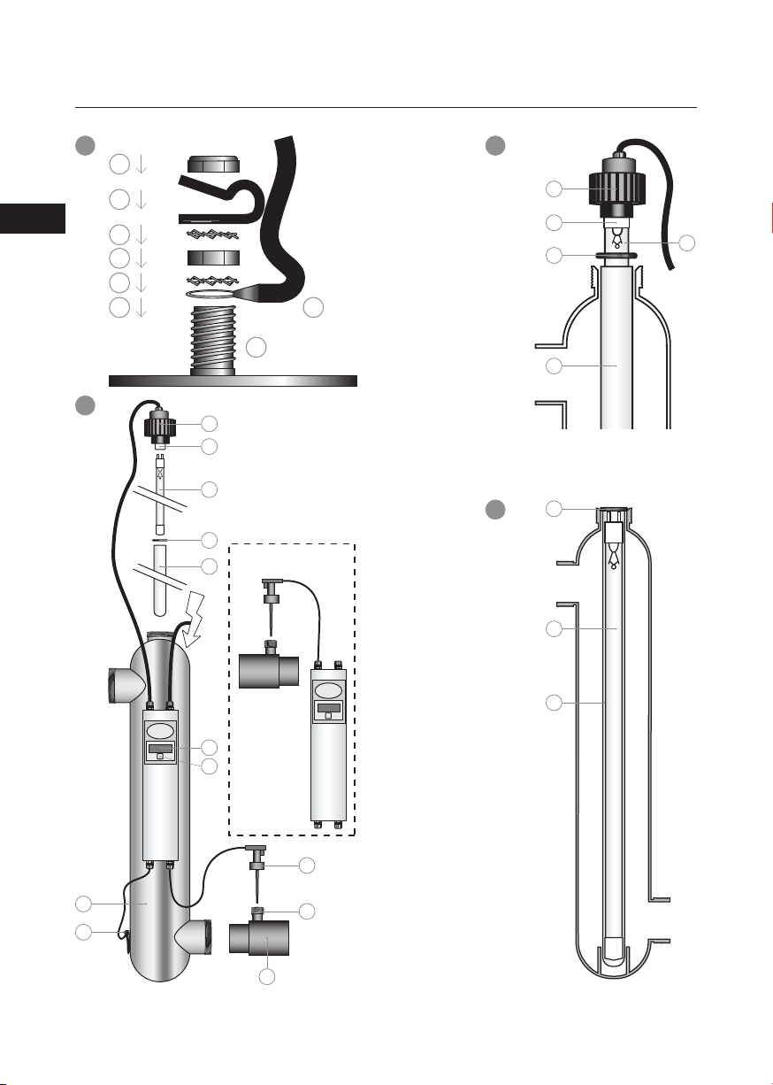
INSTALLATION OF THE EARTH (DRAWING 1)
1. Pull the cable (B) through the strain relief (F) before fitting the synthetic strain relief (F) onto
the ear th bolt (A). Position the strain relief (F) at approximately 10 cm from the eye (H) of
the ear th cable (B).
2. Place the eye (H) of the cable (B) onto the earth bolt (A) that is fitted to the housing.
3. Then place a toothed lock washer (C), a hexagon nut (D) and another toothed lock washer
(E) on top of the eye (H).
4. Fit the strain relief (F) on top, creating a loop of Ø 5 cm.
5. Finally place the lock nut (G) onto the earth bolt (A).
6. Once the various nuts have been placed onto the earth bolt (A) in the correc t sequence,
they can be tightened with a spanner or a ring spanner number 8. Do not tighten too
firmly, otherwise you may crack the strain relief. (The transparent nut that was screwed on
the ear th bolt (A) on deliver y has no further use, and can be discarded).
INSTALLATION OF THE DEVICE (DRAWING 2)
This device must never be put in the water. Always install outside the pond.
Switch the device off when administering medication.
Never install the unit in an area exposed to full sunlight. The installation must always take place
in a dry and well-ventilated area.
1. Determine where the device will be installed. Make sure to leave a free area (+/- 1 metre) in
order to be able to remove the lamp (K) / quartz glass (M) for the purpose of replacement
and/or maintenance.
2. Install the UV-C unit in a fixed position; if necessar y secure the unit onto a solid rear wall
using pipe clips (not supplied).
3. Mount the unit into the circuit. The glued socket (I) for the flow switch (X) must be glued
with the screw thread ( W) pointing upwards (see Drawing 2). The arrow on top of the flow
switch (X) must always point in the direction in which the water is flowing. The Blue Lagoon
UV-C Pro will not switch on if the flow switch is pointing in the opposite direc tion (against
the flow of the water).
4. Unscrew the screw ring (N) of the lamp on top of the housing (U). Carefully place the
quartz glass (M) in the housing (U). Place the o-ring ( T) in the correct position with regard
to the quartz glass.
5. Remove the UV-C lamp (K ) from the supplied case (see packaging) and carefully slide the
lamp into the quartz glass (M). Carefully connect the white lamp holder (L) to the UV-C
lamp (K ) and then screw the screw ring (N) hand-tight onto the housing (U). In doing this,
pay attention to the correct position of the O-ring ( T) with regard to the quartz glass.
6. Activate the pump and check the flow and any leakage of the system.
|
4

7. Put the plug of the UV-C device in a wall socket with a safety ground and fitted with a
residual current circuit-breaker. Check whether the lamp is operating by looking through
the transparent components of the unit. The unit is switched off by pulling the plug out of
the socket.
INSTRUCTIONS FOR USE OF THE DIGITAL TIME METER
As soon as the UV-C Pro is switched on, the program will carry out a self-test. The display
will automatically show the following, one after the other: 8888 (display test); r and software
version number; 50H or 60H indication of the mains frequency
Following this, the display will show the meter reading.
When the UVC lamp is switched on for the first time, or after the “reset” function has been
used, the value ‘4500’ will appear on the display. A dot next to the digit on the far right of the
display will blink every second; this indicates that the counter is running.
The display is automatically set to the factory reading of 4,500 hours. The UV-C lamp operates
at 100% radiation for up to 4,500 hours. After 4,50 0 hours, the radiation will weaken, and may
become insuf ficient to obtain the desired results.
If the UV-C lamp had already been used previously, and is switched on again, the display will
indicate the value it had at the time it was switched off earlier. If you had increased or reduced
the value of the time meter yourself, the display will indicate the latest counter reading it had
before it was switched off.
The set tings of the time meter can be modified if you wish. This is carried out as follows:
After holding down the switch (R) underneath the display for 5 seconds, the display will
show “rSt”, to indicate that the user menu has been selected. Once the switch (R) has been
released, the meter indication and “rSt” will blink alternately on the display. By briefly pressing
the switch again, it is now possible to step through the menu options. There are 3 available
setting options in the menu: “rSt” “UP” and “dn”.
• “rSt” means (reset): This option enables you to reset the meter indication to the fac tory
setting of 4,500 hours.
This selection is confirmed if the meter indication and “rSt” on the display blink alternately.
If you hold down the switch (R) for 5 seconds, after which the meter indication 4500 will
be displayed, and then release it, the time meter will start counting down from the 4,500
hour value. This selection is used if, for example, you have replaced the lamp, or if you have
modified the meter indication yourself and you want to return it to the fac tory settings.
EN
| 5

EN
• “UP” means (up): This option enables you to increase the meter indication to the desired
hour indication.
This selection is confirmed if the selected user setting ”UP” and the meter indication on
the display blink alternately. Following this, press the switch (R) down for 5 seconds. After 5
seconds, the display will only indicate “UP”. You can then release the switch.
By briefly pressing the switch, the counter value can now be increased in steps of 500 hours
from the value of 4500 up to a maximum value of 9999. The increased value and “UP” will
blink alternately on the display.
After you have selected the desired hour indication, wait for 10 seconds. After 10 seconds,
the selected hour indication will be displayed and the Pro will start counting down.
If you make a mistake while increasing the meter indication, it is possible to reset the
counter to 4500 by keeping the switch pressed down for 5 seconds. The counter value will
then be reset to 4500, and a new value can be set.
• “dn” means (down): This option enables you to decrease the meter indication to the
desired hour indication.
This selection is confirmed if the selected user setting ”dn” and the meter indication on
the display blink alternately. Following this, press the switch (R) down for 5 seconds. After 5
seconds, the display will only indicate “dn”. You can then release the switch.
By briefly pressing the switch, the counter value can now be decreased in steps of 500
hours from the value of 4500 down to a minimum value of 00 00. The decreased value and
“dn” will blink alternately on the display.
Once you have selected the desired hour indication, wait for 10 seconds. After 10 seconds,
the selected hour indication will be displayed and the Pro will start counting down.
If you make a mistake while decreasing the meter indication, it is possible to reset the
counter to 4500 by keeping the switch pressed down for 5 seconds. The counter value will
then be reset to 4500, and a new value can be set.
The time meter will indicate in the following manner that the lamp must be replaced:
• From hour position 0672; the display will blink every second. The lamp is to be replaced in
4 weeks’ time.
• From hour position 0336; the display will blink every half second; The lamp is to be
replaced in 2 weeks’ time.
• From hour position 0168; the display will blink every ¼ second; The lamp is to be replaced
in 1 week ’s time.
• At an hour position of 00 00; the digits will blink continuously, and the meter will not
continue to count down. The lamp must be replaced.
DISMANTLING / MAINTENANCE
Always switch off the power supply during maintenance/dismantling of the device.
The device must be cleaned twice a year. If there is an increase in algae and/or scale, the
|
6

quartz glass tube (M) in which the lamp is positioned must be cleaned. The special lamp must
be replaced after 4,500 operating hours. The stainless steel interior can be cleaned with a soft
brush.
1. Drain the water from the device.
2. Unscrew the screw cap (N) and disconnect the lamp (K) from the lamp holder (L). Remove
the lamp from the quartz glass and, if necessary, replace the special lamp (K). As these
parts are very fragile, caution is essential.
3. Carefully remove the quartz glass (M) (see drawing 3). Never use force!
4. Clean the quartz glass with a suitable agent. Always use a soft cloth to clean the glass in
order to prevent scratches.
5. Carefully replace the lamp in the quartz glass, put the O-ring (T) back on the quartz glass
and connect the lamp (K) to the lamp holder (L). Screw the screw cap (N) onto the housing
again.
6. The electrical unit of the device is situated in the display box (S) on the device. This display
box is glued and cannot be opened. If the electrical unit or the display is replaced, the
entire box must be unscrewed and the wiring must be disconnec ted from the device (see
drawing 1). Any loose par ts, i.e. of the earth etc., must be carefully retained, as they are
not supplied with a new housing or electrical unit. In case of any doubt with regard to the
connection, consult a recognised fitter.
7. If the housing needs replacing, the earth (J) and the electrical unit with the display (S) must
first be disconnected from the housing (U) (see drawings 1 & 2). Unscrew the electrical
unit with display (S) and the lamp holder from the housing. Be sure to carefully retain the
various loose part s of the earth, as they are not supplied with a new housing. Remove
the lamp (K) and quartz glass (M) from the housing in order to prevent breakage during
transport. In case of any doubt with regard to the connection, consult a recognised fitter.
TECHNICAL SPECIFICATIONS 75,000 L 150,000 L
Philips TUV T5 lamp 75 Watt 130 Watt
UV-C output ( W) 25 Watt 50 Watt
UV-C (%) after 4,500 hours 85% 85%
Pond content (l) 75,00 0 l 50,000 l
Max. throughput 35,000 l/h 40,0 00 l/h
Max. pressure 5 bar 5 bar
Connection size Ø50 mmm Ø50 mm
Length of the device 100 cm 100 cm
EN
| 7

EN
UV-C SYSTEM TYPES
Article number: 3300020 UV-C Pro 75,000 l / 75 Watt (230V; 50/60Hz)
Article number: 3300021 UV-C Pro 150,0 00 l / 130 Watt (230V; 50/60Hz)
REPLACEMENT LAMPS
Article number: 3903579 Philips Lamp type TUV 36T5 HO 4P-SE (75 Watt)
Article number: 3903100 Philips Lamp type TUV 130 Watt 4P-SE Amalgam (130 Watt)
TERMS OF GUARANTEE
The guarantee of this product covers manufacturing faults for a period of 24 months following
the date of purchase. The lamp and the quartz glass are not included in this guarantee. Claims
under the guarantee can only be considered if the product is returned post-paid together with
a valid purchase receipt. Repairs under the guarantee may exclusively be carried out by the
supp li er.
Guarantee claims that are caused by errors in the installation or operation of the device will
not be considered. Defects originating from poor maintenance are also excluded from the
guarantee. The supplier will in no way whatsoever be held responsible for any damage caused
by the incorrect operation of the product. The supplier will not be liable for any consequential
damage caused by the breakdown of the device. Complaints regarding transportation
damage will only be considered if the damage was established or confirmed on delivery by
the carrier or the postal authorities. A claim can only be made against the carrier or the postal
authorities if this has been done.
|
8
XCLEAR UV-C PRO 75 000 - 150 000 AMALGAM
Lesen Sie diese Gebrauchsanweisung vor dem
Installieren des Geräts sorgfältig durch.
Dieses UV-C Gerät sorgt für klares Teichwasser und gesunde Fische. Das Teichwasser wird
mittels einer Pumpe durch das UV-C-Gerät geführt, wo es einer UV-C-Strahlung mit 254
Nanometern Wellenlänge ausgesetzt wird. Diese von einer Speziallampe er zeugte Strahlung
sorgt dafür, dass im Wasser befindliche Bakterien und Krankheitserreger abgetötet werden.
Durch die Länge des Geräts wird das Wasser der hohen Strahlendosis besonders lange
ausgesetzt. Außerdem bewirk t die Edelstahl-Innenseite eine Reflexion des UV-C-Lichts,
wodurch sich die Effizienz um bis zu 35% erhöht. Das beste Ergebnis erzielen Sie, wenn Sie das
Gerät während der frostfreien Periode 24 Stunden am Tag laufen lassen. Das Teichwasser wird
innerhalb von 14 Tagen klar sein, und Ihre Koi bleiben in einem ausgezeichneten Zustand.
WIRKUNGSWEISE
• UV-C-Gerät mit Edelstahl-Innenseite
• Bis zu 35% höherer UV-C-Ertrag durch Reflexion
• Schützt Ihre Koi vor Krankheitserregern
• Hält Schimmel-, Bakterien- und Algenbildung unter Kontrolle
• Reinigt das Teichwasser ohne Einsatz von Chemikalien
• Sorgt für klares Teichwasser
• Sicher und gut für Ihre Koi
• Das UV-C Pro-Gerät ist geerdet
Dieses Gerät erzeugt schädliche Strahlen. Direkter
Kontakt kann für Augen und Haut gefährlich sein.
Prüfen Sie die Funktion der UV-C-Lampe deshalb
nur über die transparenten Teile der Einheit.
DE
SICHERHEIT
• Den Gerätestecker immer in eine Steckdose mit Schutzdeckel stecken.
• Für einen permanenten Anschluss an das Stromnetz müssen die Vorschrif ten des
Energieunternehmens erfüllt werden. Im Zweifelsfall einen anerkannten Installateur
oder das Energieunternehmen zu Rate ziehen. Grundsätzlich einen Erdschlussschalter
verwenden.
• Bei Einsatz von Wasserbehandlungsmitteln oder Medikamenten muss das Gerät
abgeschaltet werden.
• Immer den Stecker aus der Steckdose ziehen, bevor Wartungs- oder Reparaturarbeiten
am Gerät vorgenommen werden. Den Stecker nie in die Steckdose stecken bzw. aus der
Steckdose ziehen, wenn Sie in einer Pfüt ze stehen oder nasse Hände haben.
• Das Gerät auf keinen Fall unter Wasser tauchen.
• Kinder von Gerät und Kabel fernhalten.
• Das Kabel dieses Geräts kann nicht ausgetauscht werden. Bei Beschädigung des
Stromkabels muss der gesamte elek trische Teil des Geräts ausgetauscht werden. Den
Stecker nie entfernen, sondern den elektrischen Teil unversehrt lassen. Wenn der Stecker
abgeschnitten wurde, fällt der elektrische Teil nicht unter die Garantie.
| 9

DE
• Nach Ausschalten des Geräts bleibt die Lampe noch ca. 10 Minuten warm.
• Wenn Teile (insbesondere das Quarzglas) beschädigt sind, darf das Gerät nicht benutzt
werden.
• Bei Einfriergefahr in den Wintermonaten das Gerät entfernen.
• Dieses Produkt dar f nur den in dieser Gebrauchsanweisung beschriebenen Richtlinien
entsprechend eingesetzt werden.
INSTALLATION DER ERDUNG (ZEICHNUNG 1)
1. Bevor Sie die Kunststoff-Zugentlastung (F) am Massebolzen (A) anbringen, müssen Sie
erst das Kabel (B) durch die Zugentlastung (F) ziehen. Die Zugentlastung (F) in ca. 10cm
Abstand zu Öse (H) des Massekabels (B) anbringen.
2. Die Öse (H) von Kabel (B) über Massebolzen (A) anbringen, der am Gehäuse befestigt ist.
3. Anschließend eine Spannscheibe (C), Sechskantmutter (D) und noch eine Spannscheibe
(E) an der Öse (H) anbringen.
4. Zugentlastung (F) darauf befestigen, so dass eine Schleife von Ø 5cm entsteht.
5. Zuletzt die Sicherungsmutter (G) an Massebolzen (A) anbringen.
6. Wenn alle Muttern in der richtigen Reihenfolge an Massebolzen (A) angebracht wurden,
kann dieser mit einem 8er Steck- oder Ringschlüssel festgezogen werden. Ziehen Sie den
Bolzen nicht zu fest an, weil sonst die Zugentlastung reißen kann. (Die transparente Mutter,
die bei Lieferung auf den Massebolzen (A) geschraubt ist, hat keine weitere Funktion und
kann weggeworfen werden.)
INSTALLATION DES GERÄTS (ZEICHNUNG 2)
Tauchen Sie das Gerät nie unter Wasser. Installieren Sie es nur außerhalb des
Teiches. Bei der Gabe von Medikamenten muss das Gerät ausgeschaltet werden.
Das Gerät nie in der vollen Sonne installieren. Grundsätzlich in einem trockenen, gut
belüfteten Raum installieren.
1. Die Stelle bestimmen, an der das Gerät installiert werden soll. Dafür sorgen, dass genug
Platz bleibt (ca. 1 Meter), um Lampe (K)/Quarzglas (M) zu entfernen (für Austausch und/
oder Wartung).
2. Das UV-C-Gerät an einer festen Stellen anbringen; das Gerät eventuell mit Rohrschellen
(gehören nicht zum Lieferumfang) an einer stabilen Rückwand befestigen.
3. Das Gerät im Kreis anbringen. Die Klebemuffe (I) für den Durchflussschalter (X) muss mit
nach oben weisendem Gewinde (W) verklebt werden (siehe Zeichnung 2). Der kleine
Pfeil oben an Durchflussschalter ( X) muss immer in die Strömungsrichtung des Wassers
gerichtet sein. Wenn er gegen die Strömungsrichtung des Wassers weist, bleibt das Blue
Lagoon UV-C Pro-Gerät ausgeschaltet.
4. Den Schraubring (N) der Lampe oben auf dem Gehäuse vom Gehäuse (U) abschrauben.
Schieb das Quartzglas (M) vorsichtig in das Gehäuse (U). Setzen Sie den O-Ring ( T) in der
richtigen Position in Bezug auf das Quarzglas.
10 |

5. Die UV-C-Lampe (K) aus dem mitgelieferten Köcher (siehe Verpackung) nehmen und die
Lampe vorsichtig in das Quarzglas (M) schieben. Die weiße Lampenfassung (L) vorsichtig
mit der UV-C-Lampe (K) verbinden und anschließend den Schraubring (N) handfest auf
das Gehäuse (U) schrauben. Dabei auf die richtige Lage von O-Ring (T) für das Quarzglas
achten.
6. Die Pumpe in Betrieb setzen und das System auf Durchfluss und Dichtheit prüfen.
7. Den Stecker des UV-C-Geräts in eine Schukosteckdose mit Erdschlussschalter stecken.
Durch die transparenten Teile des Geräts prüfen, ob die Lampe brennt. Um das Gerät
auszuschalten, ziehen Sie den Stecker aus der Steckdose.
GEBRAUCHSANWEISUNG FÜR DEN DIGITALEN STUNDENZÄHLER
Wenn der UV-C Pro eingeschaltet ist, führt das Programm einen Selbsttest aus. Auf dem
Display erscheinen automatisch nacheinander folgende Anzeigen: 8888 (Displaytest); r und
Softwareversionsnummer; 50H oder 60H Anzeige der Netzfrequenz
Anschließend erscheint auf dem Display der Zählerstand.
Wenn die UV-C-Lampe das erste Mal eingeschaltet wird oder nachdem die “Reset”-Funktion
ausgeführt wurde, erscheint der Wert “450 0” auf dem Display. Bei der Ziffer ganz rechts auf
dem Display blinkt im Sekundentak t ein Punkt, der anzeigt, dass der Zähler läuft.
Auf dem Display wird automatisch der werkseitig eingestellte Zählerstand von 4500 Stunden
angezeigt. Bis 4500 Stunden erreicht die UV-C-Lampe 100% ihrer wirksamen Strahlung.
Nach 4500 Stunden wird die Strahlung schwächer und reicht möglicherweise nicht mehr
aus, um das gewünschte Ergebnis zu erzielen. Wenn Sie die UV-C-Lampe schon länger
verwenden und diese schon einmal eingeschaltet war, zeigt das Display nach dem Einschalten
wieder den Wert an, der dort vor dem Ausschalten der UV-C-Lampe stand. Wenn Sie
den Stundenzählerstand selbst erhöht oder verringert haben, wird der letzte Zählerstand
angezeigt, der vor dem Ausschalten auf dem Display stand.
Sie können die Einstellungen des Stundenzählers ggf. ändern. Dabei gehen Sie
folgendermaßen vor:
Wenn Sie den Schalter (R) unter dem Display 5 Sekunden eingedrück t halten, erscheint auf
dem Display “rSt”, um anzuzeigen, dass das Benutzermenü gewählt wurde. Nach Loslassen
des Schalters (R) blinken auf dem Display abwechselnd der Zählerstand und “rSt”. Wenn jetzt
der Schalter kurz eingedrückt wird, werden die Möglichkeiten des Menüs durchlaufen. Das
Menü enthält drei Einstellmöglichkeiten: “rSt” “UP” und “dn”.
DE
• “rSt” bedeutet (reset): Damit wird der Zählerstand auf die Werkseinstellung von 4500
Stunden zurückgesetzt.
bedeutet (reset): Damit wird der Zählerstand auf die Werkseinstellung von 4500
Stu nden zurückgesetzt. Diese Wahl wird auf dem Display durch abwechselndes Blinken
von Zählerstand und “rSt” bestätigt. Wenn Sie den Schalter (R) 5 Sekunden eingedrückt
halten ( Zählerstand 4500 wird angezeigt) und dann wieder loslassen, beginnt der
| 11

DE
Stundenzähler von der Stundenzahl 4500 aus rückwärts zu zählen. Diese Option wählen
Sie, wenn Sie z.B. die Lampe ausgetauscht haben oder wenn Sie den Zählerstand selbst
geändert haben und ihn wieder auf die Werkseinstellung zurücksetzen wollen.
• “UP” bedeutet (up): Hiermit können Sie den Zählerstand auf den gewünschten
Zählerstand erhöhen.
Diese Wahl wird auf dem Display durch abwechselndes Blinken der gewählten
Benutzereinstellung “UP” und des Zählerstands bestätigt. Anschließend müssen Sie den
Schalter (R) 5 Sekunden eingedrückt halten. Nach 5 Sekunden steht auf dem Display nur
noch “UP”. Jetzt müssen Sie den Schalter loslassen.
Durch kurzes Eindrücken des Schalters kann der Zähler wert ab 4500 in Schritten von
500 Stunden auf maximal 9999 erhöht werden. Der erhöhte Wert blinkt auf dem Display
abwechselnd mit “UP”.
Wenn der gewünschte Zählerstand erreicht ist, warten Sie 10 Sekunden. Nach 10
Sekunden erscheint die gewählte Stundenzahl, und der Pro beginnt rückwärts zu zählen.
Wenn Sie sich z.B. beim Erhöhen des Zählerstands geirrt haben, können Sie den Zähler
wieder auf 4500 zurücksetzen, indem Sie den Schalter 5 Sekunden eingedrückt halten. Der
Zählerstand beträgt dann wieder 4500, und es kann ein neuer Wert eingestellt werden.
• “dn” bedeutet (down): Hiermit können Sie den Zählerstand auf die gewünschte
Stundenzahl verringern.
Diese Wahl wird auf dem Display durch abwechselndes Blinken der gewählten
Benutzereinstellung “dn” und des Zählerstandes bestätigt. Anschließend müssen Sie den
Schalter (R) 5 Sekunden eingedrückt halten. Nach 5 Sekunden steht auf dem Display nur
noch “dn”. Jetzt müssen Sie den Schalter loslassen.
Durch kurzes Eindrücken des Schalters kann der Zählerstand ab 4500 in Schritten von 500
Stunden auf minimal 0000 verringer t werden. Der verringerte Wert blinkt auf dem Display
abwechselnd mit “dn”.
Wenn der gewünschte Zählerstand erreicht ist, warten Sie 10 Sekunden. Nach 10
Sekunden erscheint die gewählte Stundenzahl, und der Pro beginnt rückwärts zu zählen.
Wenn Sie sich z.B. beim Verringern des Zählerstands geirr t haben, können Sie den Zähler
wieder auf 4500 zurücksetzen, indem Sie den Schalter 5 Sekunden eingedrückt halten. Der
Zählerstand beträgt dann wieder 4500, und es kann ein neuer Wert eingestellt werden.
12 |
Der Stundenzähler zeigt auf die folgende Weise an, dass die Lampe ausgetauscht werden muss.
• Ab Zählerstand 0672: Display blinkt im Sekundentakt. Die Lampe muss in 4 Wochen
ausgetauscht werden.
• Ab Zählerstand 0336: Display blinkt alle halbe Sekunde. Die Lampe muss in 2 Wochen
ausgetauscht werden.
• Ab Zählerstand 0168: Display blinkt alle 1/4 Sekunde. Die Lampe muss in 1 Woche
ausgetauscht werden.

• Bei einem Zählerstand von 0000 blinken die Ziffern in hohem Tempo weiter, und der
Zähler zählt nicht mehr zurück. Die Lampe muss ausgetauscht werden.
DEMONTAGE/WARTUNG
Bei Demontage/War tung des Geräts grundsätzlich erst die Stromzufuhr ausschalten.
Das Gerät muss 2-mal im Jahr gereinigt werden. Wenn Algenwachstum und/oder
Kalkablagerungen zunehmen, muss die Quarzglasröhre (M), in der die Lampe steckt, gereinigt
werden. Die Speziallampe muss nach 4.500 Brennstunden ausgetauscht werden. Die
Edelstahl-Innenverkleidung mit einer weichen Bürste reinigen.
1. Das Wasser aus dem Gerät strömen lassen.
2. Den Schraubring (N) abschrauben und die Lampe (K) von der Lampenfassung (L) trennen.
Die Lampe aus dem Quarzglas nehmen und erforderlichenfalls die Speziallampe (K )
austauschen. Vorsicht ist geboten, weil es sich hier um sehr empfindliche Teile handelt.
3. Das Quarzglas (M) vorsichtig entfernen (siehe Zeichnung 3). Auf keinen Fall gewaltsam
vorgehen!
4. Das Quarzglas mit einem geeigneten Mittel reinigen. Zum Reinigen des Quarzglases
immer ein weiches Tuch verwenden und Kratzer vermeiden.
5. Die Lampe vorsichtig wieder in das Quarzglas einsetzen, den O-Ring (T) wieder
am Quarzglas anbringen und die Lampe (K) mit der Lampenfassung (L) verbinden.
Schraubring (N) wieder auf das Gehäuse schrauben.
6. Der elektrische Teil des Geräts befindet sich im Displaygehäuse (S) am Gerät. Das
Displaygehäuse ist geklebt und kann nicht geöffnet werden. Zum Auswechseln des
elektrischen Teils oder des Displays muss das ganze Gehäuse losgeschraubt und die
Verkabelung des Geräts gelöst werden (siehe Zeichnung 1). Die verschiedenen Einzelteile,
z.B. für die Erdung, immer gut aufbewahren. Diese Teile werden nicht mit einem neuen
Gehäuse oder elektrischen Teil mitgeliefert. Im Zweifelsfall für den Anschluss einen
anerkannten Installateur hinzuziehen.
7. Wenn das Gehäuse ausgetauscht werden soll, müssen erst die Erdung (J) und der
elektrische Teil mit Display (S) vom Gehäuse (U) gelöst werden (siehe Zeichnung 1 & 2).
Elektrischen Teil mit Display (S) und Lampenfassung vom Gehäuse abschrauben. Die
verschiedenen Einzelteile der Erdung immer gut auf bewahren. Sie werden nicht mit einem
neuen Gehäuse mitgeliefert. Lampe (K) und Quarzglas (M) aus dem Gehäuse entfernen,
um Bruchschäden beim Transport zu vermeiden. Im Zweifelsfall für den Anschluss einen
anerkannten Installateur hinzuziehen.
DE
| 13

DE
TECHNISCHE DATEN 75.000 LITER 150.000 LITER
• Lampe Philips TUV T5 75 Watt 130 Watt
• UV-C-Leistung (W) 25 Watt 50 Watt
• UV-C (%) nach 4.500 Stunden 85% 85%
• Teichgrösse (Liter) 75.00 0 Liter 150.00 0 Liter
• Max. Durchfluss 35.000 l/h 4 0.000 l/h
• Max. Druck 5 bar 5 bar
• Anschluss Ø50mm Ø50mm
• Länge des Geräts 100cm 100cm
TYP UV-C-SYSTEME
Artikelnummer: 3903579 Philips-Lampe Typ TUV 36T5 HO 4P-SE (75 Wat t)
Artikelnummer: 3903100 Philip-Lampe Typ TUV 130 Watt 4P-SE Amalgam (130 Watt)
ERSATZLAMPEN
Article number: 3903579 Philips Lamp type TUV 36T5 HO 4P-SE (75 Watt)
Article number: 3903100 Philips Lamp type TUV 130 Watt 4P-SE Amalgam (130 Watt)
GARANTIEBEDINGUNGEN
Auf das Produkt wird für die Dauer von 24 Monaten nach dem Kaufdatum eine Garantie gegen
Herstellungsfehler gewährt. Lampe und Quarzglas sind von der Garantie ausgeschlossen.
Garantiefälle können nur bearbeitet werden, wenn das Produkt portofrei zusammen mit einem
gültigen Kaufnachweis eingeschickt wird. Reparaturen im Rahmen der Garantie dürfen nur
vom Lieferanten ausgeführt werden.
Garantieansprüche infolge von Installations- oder Bedienungsfehlern werden nicht
anerkannt. Aus mangelhafter Wartung resultierende Schäden sind ebenfalls von der Garantie
ausgeschlossen. Der Lieferant ist in keiner Weise für Schäden verantwortlich, die durch einen
falschen Einsatz des Geräts verursacht werden. Der Lieferant kann nicht für Folgeschäden
haftbar gemacht werden, die durch den Ausfall des Geräts verursacht werden. Reklamationen
aufgrund von Transportschäden können nur angenommen werden, wenn die Beschädigung
bei der Lieferung durch die Spedition oder das Postunternehmen festgestellt oder bestätigt
wird. Nur dann ist es möglich, die Spedition oder das Postunternehmen haftbar zu machen.
14 |
XCLEAR UV-C PRO 75 000 - 150 000 AMALGAM
Avant d’installer cet appareil, lire attentivement
cette notice d’utilisation.
Cet appareil UV-C permet d’obtenir un bassin à l’eau claire avec des poissons sains. Une
pompe refoule l’eau du bassin à travers l’appareil UV-C, où elle est soumise à un rayonnement
UV-C d’une longueur d’onde de 254 nanomètres. Ce rayonnement est généré par une lampe
spéciale et fait en sor te que les bactéries et les germes pathogènes ne puissent pas se
développer. Grâce à la longueur de l’appareil, l’eau est soumise pendant un temps prolongé
à la forte dose de rayonnement. De plus, la section interne en acier inoxydable assure une
réflexion du rayonnement UV-C, ce qui permet d’améliorer l’efficacité jusqu’à 35%. Pour
obtenir un résultat optimal, cet appareil doit normalement être mis en service 24 heures par
jour pendant la période où il ne gèle jamais. Grâce au UV-C Pro, l’eau de votre bassin devient
claire dans les 14 jours et vos Koi sont en excellente condition.
FONCTIONNEMENT
• Appareil UV-C avec sec tion interne en acier inoxydable
• Génération supplémentaire d’UV-C jusqu’à 35% suite à la réflexion
• Protège vos Koi contre les germes pathogènes
• Maintient la formation de moisissures, de bac téries et d’algues sous contrôle
• Nettoie l’eau du bassin sans utilisation de produits chimiques
• Rend l’eau de votre bassin claire
• Sûr et bénéfique pour vos Koi
• Le UV-C Pro est mis à la terre
Cet appareil produit un rayonnement nocif. Un contact
direc t peut entraîner des lésions aux yeux et à la peau.
Par conséquent, contrôler le fonctionnement de la lampe UV
exclusivement par le biais des pièces transparentes de l’unité.
SÉCURITÉ
• Placer toujours la fiche de l’appareil dans une prise dotée d’un clapet de fermeture.
• En cas de branchement permanent sur le réseau d’électricité, il faut respecter les
prescriptions du fournisseur d’énergie. En cas de doute concernant le branchement,
consulter un installateur agréé ou le fournisseur d’énergie. Travailler toujours avec un
interrupteur de défaut de terre.
• Lors de l’utilisation d’agents de traitement de l’eau ou de médicaments, l’appareil doit être
désactivé.
• Toujours retirer la fiche de la prise murale avant de procéder à des travaux d’entretien
ou de réparation à l’appareil. Ne jamais insérer/retirer la fiche de la prise murale avec des
mains mouillées ou avec les pieds dans une flaque d’eau.
• Ne jamais immerger cet appareil.
• Maintenir les enfants à l’écart de cet appareil et du câble.
• Le câble de cet appareil n’est pas remplaçable. En cas de dommage au câble de courant,
il faut remplacer la sec tion électrique complète de l’appareil. Ne jamais déposer la fiche,
mais laisser la section élec trique intacte. Une section électrique avec une fiche coupée
FR
| 15

FR
n’est pas couverte par la garantie.
• Après désac tivation de l’appareil, la lampe reste chaude pendant encore 10 minutes
environ.
• En cas d’endommagement de pièces (surtout du verre de quartz), ne pas utiliser l’appareil.
• En cas de risque de gel en hiver, ranger l’appareil.
• Ce produit doit uniquement être utilisé conformément aux directives reprises dans cette
notice d’utilisation.
INSTALLATION DU CÂBLE DE MISE À L A TERRE (FIGURE 1)
1. Avant de monter le serre-câble plastique (F) sur la vis de mise à la terre (A), il faut tirer le
câble (B) à travers le serre-câble (F). Placer le serre-câble (F) à environ 10 cm de l’oeil (H) du
câble de mise à la terre (B).
2. Placer l’oeil (H) du câble (B) sur la vis de mise à la terre (A) fixée sur le logement.
3. Placer ensuite une bague de retenue dentée (C), un écrou six-pans (D) et à nouveau une
bague de retenue dentée (E) sur l’oeil (H).
4. Fixer le serre-câble (F) sur ces pièces de sorte à constituer une boucle de Ø 5cm.
5. Placer en dernier lieu l’écrou-frein (G) sur la vis de mise à la terre (A).
6. Lorsque les divers écrous sont placés dans l’ordre correc t sur la vis de mise à la terre (A), ils
peuvent être serrés au moyen d’une clé à fourche ou polygonale numéro 8. Ne pas serrer
excessivement, sinon le serre-câble pourrait se fissurer.
INSTALLATION DE L’APPAREIL (FIGURE 2)
Ne jamais immerger cet appareil. L’installation doit toujours s’effec tuer à
l’extérieur du bassin. En cas d’utilisation de médicaments, l’appareil doit être mis hors
fonction.
Ne jamais installer l’appareil en plein soleil. Toujours installer l’appareil dans un local sec et
bien ventilé.
1. Déterminer la position souhaitée de l’appareil. Veiller à laisser suffisamment d’espace (+/- 1
m.) afin de pouvoir procéder au remplacement et/ou à l’entretien de la lampe (K)/du verre
de quar tz (M).
2. Monter l’unité UV-C en un endroit ferme, fixer éventuellement l’unité avec des pinces de
tube (non livrées) sur une paroi arrière solide.
3. Monter l’unité dans le circuit. La gaine de colle (I) pour le contacteur de flux (X) doit être
collée avec le filetage (W) dirigé vers le haut (voir figure 2). La flèche sur le contacteur de
flux (X) doit toujours être dirigée dans le sens de circulation de l’eau. Si cette flèche pointe
dans la direction opposée au sens de circulation de l’eau, le Blue Lagoon UV-C Pro reste
désactivé
4. Dévisser la bague à vis (N) de la lampe au sommet du logement (U). Placez délicatement le
verre de quartz (M) dans le logement (U). Placez le joint torique (T) dans la bonne position
en ce qui concerne le verre de quartz.
16 |

5. Sortir la lampe UV-C (K) de l’étui livré (voir emballage) et glisser la lampe avec précaution
dans le verre de quart z (M). Coupler avec précaution le culot de lampe blanc (L) à la lampe
UV-C (K ) et visser ensuite la bague à vis (N) à la main sur le logement (U). Lors de cette
opération, veiller au positionnement correct du joint torique (T) par rapport au verre de
quartz.
6. Activer la pompe et s’assurer que l’eau circule dans le système et qu’il n’y a pas de fuites.
7. Insérer la fiche de l’appareil UV-C dans une prise murale avec mise à la terre et dotée d’un
interrupteur de défaut de terre. S’assurer que la lampe est allumée par le biais des pièces
transparentes de l’appareil. Pour désac tiver complètement l’appareil, retirer la fiche de la
prise murale.
MODE D’EMPLOI DU COMPTEUR HORAIRE NUMÉRIQUE
Lorsque le UV-C Pro est activé, le programme procède à un autodiagnostic. L’écran affiche
automatiquement et successivement les indications suivantes : 8888: test de l’écran ; r et
numéro de version du logiciel ; 50H ou 60H, indication de la fréquence du réseau
Ensuite, l’écran affiche le statut du compteur.
Lorsque la lampe UVC est activée pour la première fois ou après utilisation de la fonction
“réinitialisation”, la valeur 4500 s’affiche sur l’écran. A proximité du chiffre à l’extrême droite de
l’écran, un point clignote chaque seconde pour indiquer que le compteur est en service.
L’écran affiche automatiquement la valeur de compteur 4500 heures réglée en usine.
Jusqu’à 450 0 heures, le rayonnement de la lampe UV-C agit à 100%. Après 450 0 heures, le
rayonnement décroît et peut être insuffisant pour obtenir les résultats souhaités.
Si la lampe UVC est utilisée depuis un cer tain temps déjà et si elle est désactivée, l’écran
affiche, après la réactivation, la valeur consignée avant la désactivation de la lampe UV-C. Si la
valeur du compteur horaire a été augmentée ou diminuée par l’utilisateur, la dernière valeur
avant sa désactivation s’affiche.
Le cas échéant, il est possible de modifier les réglages du compteur horaire. Procéder
comme suit :
Après avoir maintenu enfoncé durant 5 secondes l’interrupteur (R) sous l’écran, ce dernier
affiche “rSt” pour indiquer que le menu utilisateur a été sélectionné. Après avoir relâché
l’interrupteur (R), la valeur du compteur et “rSt” clignotent sur l’écran. En appuyant ensuite
brièvement sur l’interrupteur, il est possible de naviguer parmi les paramètres du menu. Il
existe 3 possibilités de paramétrage : “rSt” “UP” et “dn”.
FR
• “rSt” signifie (reset) : permet de remet tre le compteur horaire sur la valeur usine
de 450 0 heures.
Cette sélection est confirmée par le clignotement successif de la valeur du compteur
et de “rSt” sur l’écran. Si l’interrupteur (R) est maintenu enfoncé durant 5 secondes, ce
qui entraîne l’affichage de la valeur 450 0, et est ensuite relâché, le compteur horaire
| 17
 Loading...