

Page 1
Copyright © 2015 Ruckus Wireless,
Inc.
Published May 2015
Xclaim Xo-1
802.11ac
Wi-Fi Access
Point
Quick Setup
Guide
This Quick Setup Guide provides step-by-step instructions
on how to set up one or more Xclaim Access Points. After
completing the steps described in this Guide, you will be
able to install the Access Points (APs) at your site and
provide wireless network access to users.
BEFORE YOU BEGIN
Your Xclaim Access Point can be managed either by the
“CloudManager for Xclaim” web application or the
“Harmony for Xclaim” mobile application.
If you decide to use Harmony to manage your Access
Points locally, you will need to download the Harmony for
Xclaim mobile application. Harmony is supported on iOS
platforms (iPhone, iTouch and iPad) and can be
downloaded for free from Apple store. Harmony is also
available for Android Smartphones and can be downloaded
for free from the Google Play store.
PACKAGE CONTENTS
• Xclaim Xo-1 Access Point
• Mounting screws and anchors (2)
• Security screw
• Unit removal pin
• Regulatory flyer
• Product warranty statement
• 1 x Cat5e Patch Cable
• 1 x 802.3af PoE Injector
• This Quick Setup Guide
SETUP R
EQUIREMENTS
You will need:
• An iOS or Android device with the “Harmony for
Xclaim” application loaded and running
(or)
An account on CloudManager for Xclaim.
• A modem (DSL or cable), broadband router, or other
device provided by your Internet Service Provider
that brings Internet access to your site.
• A DHCP server to provide IP addresses to your
Access Point and wireless clients that connect to it.
• Either a PoE injector (supplied) or an optional 12V
power supply (purchased separately) or your own
802.3af or 802.3at compliant PoE switch.
STEP 1: IN ITI A L C ON FIG U RAT IO N
Setting up the Access Point
You can initially set up your Xclaim Access Points in one
location and then later relocate them when you are satisfied
with the configuration
1 Remove the Xclaim Access Point from its
packaging
2 Power up the Access Point
a. Connect the Access Point to a 802.3af
(PoE) compliant switch.
b. Alternatively, Plug in the supplied PoE
injector to a convenient and protected
power outlet
3 Connect the “PoE out” port of the PoE injector to
the Xclaim Access Point
4 Connect the remaining Ethernet port on the PoE
injector to a spare port on your Ethernet switch or
DSL/Cable Modem
5 Once power has been supplied to the Xclaim
Access Point, verify that the Power Indicator on
the Xclaim Access Point is illuminated.
Option #1 - Setting up your CloudManager account
1.
Visit http://www.xclaimwireless.com and register
for an account. Enter a valid email-ID, username
and password.
2.
Login with either the username or email ID to
access your account.
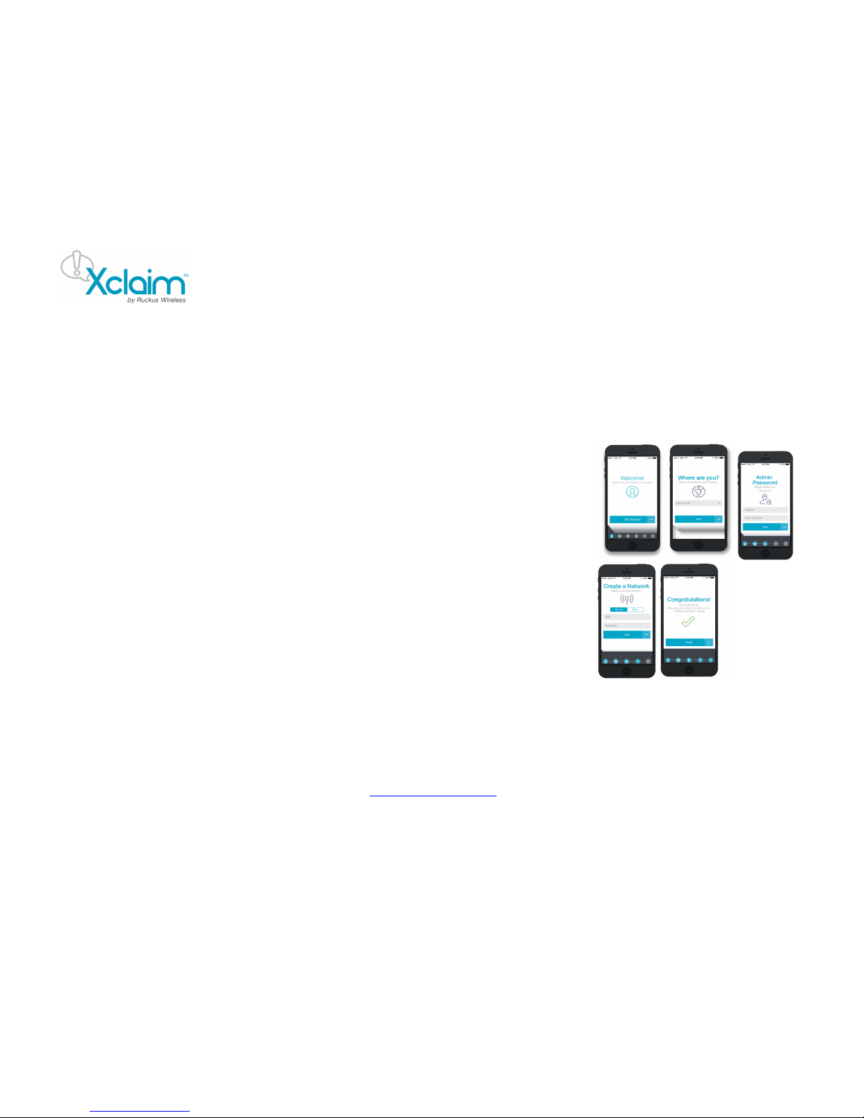
Option #2 - Setting up HARMONY
1. After installing Harmony, open the mobile
application. You will now enter the setup Wizard.
2. Select the c ountry, which will in turn be pushed to
Access Points and acts as the regulatory domain
for all your Access Points.
3. Please create the “Admin” password. This
password will be used to login to the mobile
application and will also be synced with the
Access Point.
4. The next screen allows you to create a network to
assign to Access Points later. You can choose to
skip this if you wish.
5. Click “Finis h”. You are now ready to start
configuring your Access Point using Harmony.
STEP 2: Re g is ter /Cl ai m Access Point(s)
Option #1 - Via CloudManager
1. When logging in for the first time, you will be
automatically shown the “Register Access Point”
page.
2. Please enter the serial number of the Access
Point (found at the back of the Access Point),
configure an Access Point name and other
parameters and click “Save”.
3. Your Access Point is now “claimed/registered”
Page 2

Copyright © 2015 Ruckus Wireless,
Inc.
Published May 2015
and you are ready to apply configurations to the
Access Point.
4. The Access Point’s LED color should now be
“SOLID/CONSTANT GREEN”
Option # 2- Via Harmony
1 Make sure that Wi-Fi is enabled on your tablet or
smartphone
2 Before you open the Harmony application,
connect to the “Xclaim Set-Up” Wi-Fi SSID
3 Open the Harmony application
4 Login using the password that was configured
during Harmony’s setup.
5 The Harmony application will open and locate all
Xclaim APs deployed on your network
6 Tap on the AP to configure. This should open up
the AP configuration page. Enter the AP details
and click on Save.
The AP’s LED should now be “SOLID/CONSTANT GREEN
STEP 3: Create Network(s) / WLAN(s) / SSID(s)
Option #1 - Via CloudManager
1. Click the “Networks” tab in the top panel. This will
take you to the Networks page.
2. Click the “Add New Network+” link in the left-side
panel. This will show you the “Add new network”
page.
3.
Configure the network with required parameters
and click Save.
Option #2 - Via HARMONY
1 Open Harmony and tap the Configure ->
Networks tab.
2 Click the “+” icon at the top right corner to add a
network.
3 This will allow you to create a new network.
Configure the network/WLAN with the required
settings.
4 Click Save once you are done.
STEP 3: Attaching the created network to the Access
Point.
Option #1 - Via CloudManager
1. Click the “Access Points” tab in the top panel. This
should take you back to the Access point’s page.
2. Click the Access Point that you would like to
configure.
3. A right side-panel should now open up. In t hat
side-panel, please click the “Edit Access Point”
link. This should take you to the Edit Access Point
page.
4. In the “Add Networks” section, type in the SSID
name of the network created in the previous step.
CloudManager should autocomplete the SSID
name for you.
5. Click “Save” to save the configuration and apply it
to the Access Point.
6. You will now notice that the “xclaim-setup” SSID is
automatically disabled and the custom WLAN that
you applied is enabled on the Access Point.
Option #2 - Via HARMONY
1 Open Harmony and tap the Configure -> Access
Points tab.
2 Tap the Access Point that you would like to
configure.
3 Scroll down to the bottom of the page and tap the
network name that should have been created
earlier.
4 Click “Save”, to save the configuration and apply
it to the Access Point.
5 You will now notice that the “xclaim-setup” SSID is
automatically disabled and the custom WLAN that
you applied is enabled on the Access Point.
STEP 5: Place the Access Point
1 Move the Access Point to its permanent location.
2 Use an Ethernet cable to connect the
10/100/1000 port of the Access Point to your
network.
NOTE: If you will be using PoE, you will need a
Cat 5e (or better) Ethernet cable to connect the
Access Point to the supplied PoE injector or directly
to an existing PoE switch. Also, please ensure that
the distance from the PoE switch to the Access
Point not exceed 100m(328 ft.).
3 If using the supplied PoE adapter, connect this to
a suitable power source.
4 Verify that the 10/100/1000 Ethernet ports’ LED is
lit on the Access Point.
STEP 6: Verify your installation
1 Using any wireless-enabled computer or mobile
device, search for and select the wireless
network you previously configured
2 If you can connect, open a browser and link to
any public web site.
Congratulations! Your wireless network is active and ready for
use. If you need to configure advanced wireless settings,
such as enabling security, see the Xclaim Access Point User
Guide.
Page 3
Copyright © 2015 Ruckus Wireless,
Inc.
Published May 2015
(OPTIONAL) MOUNTING INSTRUCTIONS
Xo-1 ANTENNA COVERAGE
The Xo-1 AP includes internal omni 5GHz and 2.4GHz
antennas, and has two female N-type connector for optional
customer-ordered external 5GHz antennas.
Internal Omni Antennas
When the internal antennas are used, the Xo-1 is best
deployed where lateral beamforming can provide the greatest
reach and throughput to a wide coverage area, or to provide
the greatest distance between APs in a connecting mesh
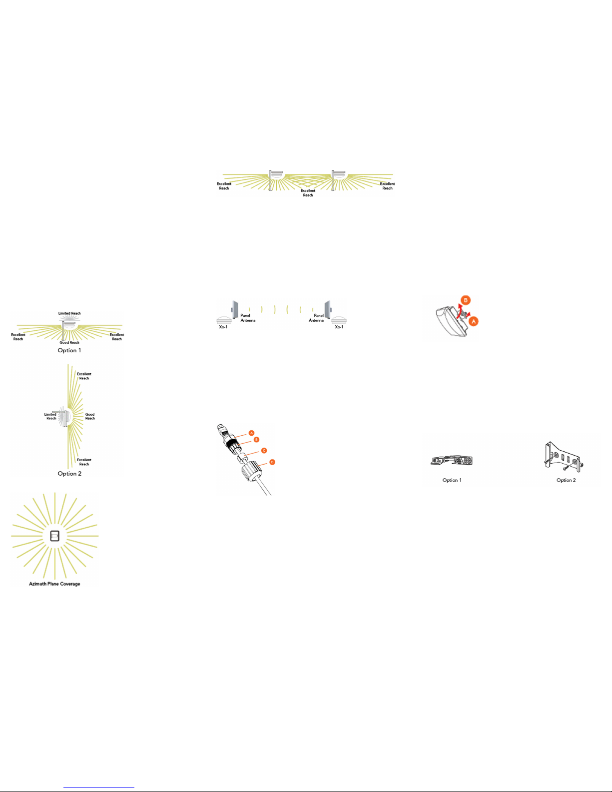
device. See Figure 1 for a typical side view coverage pattern,
see Figure 2 for a typical top view coverage pattern, and see
Figure 3 for a typical mesh coverage pattern.
Figure 1 – Typical AP internal omni coverage, side view
Figure 2 – Typical AP internal omni coverage, top view
Figure 3 – Typical AP internal-antenna mesh elevation plane
coverage, side view
External Customer-Supplied 5GHz Antennas
Instead of the internal omni 5GHz antennas, the Xo-1 can use
one or two external 5GHz antennas in point-to-point and other
specialized deployments for extended backhaul, higher
throughput, and/or larger or smaller beamwidths than those
provided by Ruckus Wireless AP internal antennas.
Figure 4 shows the Xo-1 used in a typical backhaul
deployment.
Figure 4 – Typical AP long-range point-to-point deployment
Step 1: Connecting and Sealing the RJ-45 Cable
The AP uses one RJ-45 cable for Ethernet backhaul and
Power over Ethernet (PoE). Connect and seal the cable using
the M25 data cable gland.
Feed the end of the RJ-45 cable through the sealing nut (D in
Figure 5), rubber sealing insert (C in Figure 5), clamping ring
assembly (B in Figure 5) and cable gland base (A in Figure 5).
Figure 5 – RJ-45 cable and cable gland assembly
Use a wide flat-blade screwdriver to remove the blanking cap
from the AP.
Connect the cable to the Ethernet port in the AP.
Tighten the cable gland base into the AP chassis to 7 N.m or
62 in-lbs.
Wrap the clamping ring assembly around the rubber sealing
insert. Make sure that the clamping ring assembly fully
encloses the rubber sealing insert.
Seat the clamping ring assembly and rubber sealing insert in
the cable gland base.
Tighten the sealing nut to 1.1 N.m or 10 in-lbs, or until the
rubber sealing insert is compressed.
Continue with Step 2a: Attaching the Mounting Bracket to a
Flat Surface or Step 2b: Attaching the Mounting Bracket to a
Metal Pole.
Step 2a: Attaching the Mounting Bracket to a Flat
Surface
The AP mounting bracket attaches to the AP using a captive
screw. Use a medium flat-blade or No. 2 Phillips screwdriver to
loosen the captive screw (A in Figure 6) and pull up on the end
of the bracket to remove the bracket from the AP (B in Figure
6).
Figure 6 – Removing the mounting bracket
Using either of the two options shown in Figure 7, hold the
mounting bracket at the location on the mounting surface
where you want to mount the AP. Use the holes on the
mounting bracket as a template to mark the locations of the
mounting holes.
NOTE: The mounting bracket can be mounted to a vertical or
horizontal surface to support the AP in the required orientation.
Figure 7 – Mounting bracket on a flat surface
Remove the mounting bracket from the mounting surface.
Drill holes required for the customer-supplied mounting
hardware.
Attach the mounting bracket to the flat surface using the
mounting hardware.
Using the mounting hardware instructions, tighten the hardware
to secure the mounting bracket.
Continue with Step 3: Mounting the AP.
Page 4
Copyright © 2015 Ruckus Wireless,
Inc.
Published May 2015
Step 2b: Attaching the Mounting Bracket to a Metal
Pole
The AP mounting bracket attaches to the AP using a captive
screw. Loosen the screw (A in Figure 6) and pull up on the end
of the bracket to remove the bracket from the AP (B in Figure
6).
Insert the open end of one steel clamp into two of the slots on
the mounting bracket.
NOTE: The mounting bracket can be mounted to a vertical or
horizontal pole to support the AP in the required orientation.
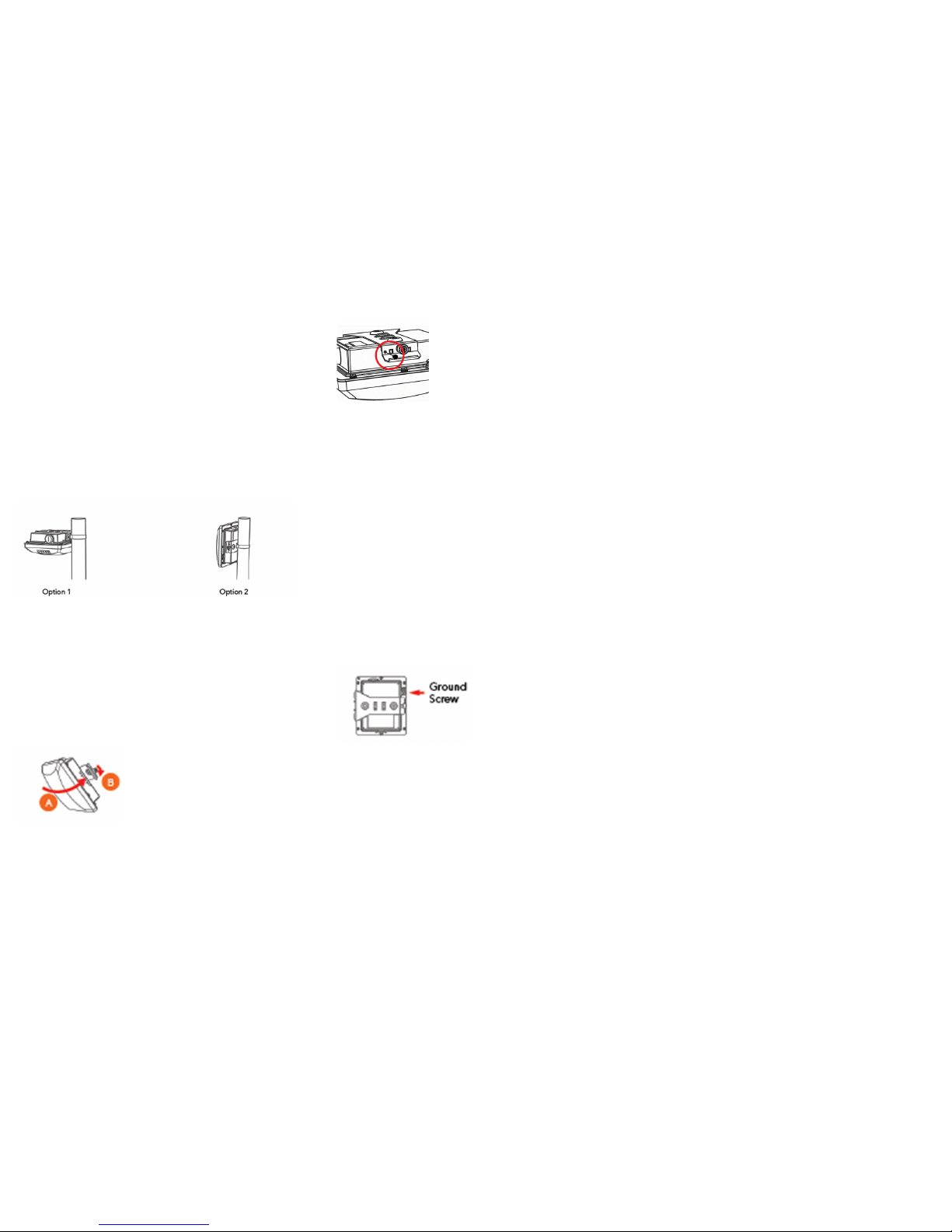
Using either of the two options shown in Figure 8, use the
clamp(s) to attach the mounting bracket to the pole. Tighten the
clamps to 3 N.m or 27 in-lbs, or per manufacturer’s
specifications if the factory-supplied clamps are not used.
If necessary, daisy-chain the other steel clamps to
accommodate larger poles.
Figure 8 – Mounting bracket on a pole
Continue with Step 3: Mounting the AP.
Step 3: Mounting the AP
Snap the AP back onto the mounting bracket (A in Figure 9),
and use a medium flat-blade or No. 2 Phillips screwdriver to
tighten the captive screw to 1.1 N.m or 10 in-lbs to secure the
bracket to the AP (B in Figure 9).
Figure 9 – Attaching the mounting bracket to the AP
Optional Step: If you also need to lock the mounting bracket to
the AP, then use a matching security screwdriver to screw the
customer-supplied locking stainless steel 6mm M3 panhead
security screw through the mounting bracket and into the AP
chassis.
CAUTION: Make sure that the customer-supplied locking
stainless steel M3 panhead security screw is no longer than
6mm. If the security screw is longer than 6mm, it can damage
the AP chassis.
Figure 10 – Locking the mounting bracket to the AP
Continue with Step 4: Earth Grounding the AP.
Step 4: Earth Grounding the AP
CAUTION: Make sure that earth grounding is available and
that it meets local and national electrical codes. For additional
lightning protection, use lightning rods and lightning arrestors.
NOTE: The color coding of ground wires varies by region.
Before completing this step, check your local wiring standards
for guidance.
Using the factory-supplied ground wire and ground screw,
connect a good earth ground to the AP chassis ground point (A
in Figure 12).
CAUTION: The Xo-1 AP includes one 12mm stainless steel
M6x1 earth ground screw with split lock and flat washers. Make
sure that any replacement screw is no longer than 12mm. If a
screw is longer than 12mm, it can damage the AP chassis.
Figure 11 – Connect good earth ground to the AP here
Optional Step 5: Mounting and Connecting an External
5GHz Antenna
You can optionally connect two customer-ordered 5GHz
external antennas to the standard N-type female connectors on
the Xo-1 AP.
Disconnect the AP from its power source.
WARNING: Before connecting the antennas to the AP, make
sure that you disconnect the AP from the power source.
NOTE: Refer to Required Hardware and Tools for information
on tested 5GHz external antennas.
Unscrew the metal caps that protect the antenna connectors.
Place the metal caps in a safe place for later use.
If the antennas come with RF coaxial cables (for example, a
patch antenna), then physically mount the antenna, preferably
on the same mounting structure as the AP.
NOTE: Mount the external antennas at least 20cm (7.9”) away
from each other and away from other antennas, if possible.
If the antennas do not use RF coaxial cables, then connect the
antennas directly to the antenna connectors on the AP. Use a
torque wrench to tighten the connectors to 1.58 N.m (14 in-lbs).
Follow all instructions provided by the antenna manufacturer.
--OR--
If the antennas do use RF coaxial cables, then connect the
antennas to the antenna connectors on the AP and on the
antennas. Use a torque wrench to tighten the connectors to
1.58 N.m (14 in-lbs). Follow all instructions provided by the
antenna manufacturer.
Apply weatherproofing tape to the antenna connectors as
described in the Ruckus Wireless N-Type Connector Sealing
Instructions.
Refer to the Xo-1 802.11ac Outdoor Access Point Installation
Guide and enable the 5GHz external antennas, and then set
the 5GHz external antenna gain.
CAUTION: If you are not connecting external antennas to the
AP, then make sure that the metal caps remain installed and
securely fastened to protect the interfaces from elements, such
as water and dirt.
Congratulations! You have mounted your Xo-1 access point.
 Loading...