


Bedienungsanleitung
Manual
Mode d‘emploi
#50500000 Sender X-6S
#50500000 Transmitter X-6S
#50500000 Émetteur X-6S

2
50500000 Sender X-6S
DE
Inhalt
Impressum
Diese Bedienungsanleitung ist eine Publikation der
XciteRC Modellbau GmbH & Co. KG
Autenbachstrasse 12
D-73035 Göppingen
Phone: +49 7161 40 799 0
Fax: +49 7161 40 799 99
E-Mail: info@xciterc.de
Web: www.XciteRC.de
Alle Rechte einschließlich Übersetzung vorbehalten. Reproduktionen jeder Art, z. B. Fotokopie, Mikroverfilmung, oder die
Erfassung in elektronischen Datenverarbeitungsanlagen, bedürfen der schriftlichen Genehmigung des Herausgebers. Nachdruck, auch auszugsweise, verboten.
Diese Bedienungsanleitung entspricht dem technischen Stand des Produkts bei Drucklegung, Änderung in Technik und
Ausstattung vorbehalten. Aus Angaben und Abbildungen dieser Bedienungsanleitung können keine Ansprüche abgeleitet
werden.
KEINE HAFTUNG FÜR DRUCKFEHLER! ÄNDERUNGEN VORBEHALTEN!
Die jeweils neueste Version dieser Anleitung finden Sie im Internet unter www.XciteRC.de
© Copyright 2013 by XciteRC-Modellbau GmbH & Co. KG
Inhaltsverzeichnis
Bestimmungsgemäße Verwendung ..........................................................................................................3
Lieferumfang ............................................................................................................................................3
Erklärung der Gefahrensymbole ...............................................................................................................3
SICHERHEITSHINWEISE ..........................................................................................................................4
Sicherheitshinweise zum Umgang mit Batterien bzw. Akkus: ....................................................................5
Der Sender ...............................................................................................................................................6
Binden des Empfängers ...........................................................................................................................6
Grundlegende Funktionen.........................................................................................................................7
Die Grundanzeige .....................................................................................................................................7
LED- und Funktionsanzeige .....................................................................................................................7
Menüs ......................................................................................................................................................8
Navigation in den Menüs ..........................................................................................................................8
SystemMenü Übersicht ............................................................................................................................9
Funktions-Menü (Heli) .............................................................................................................................14
Funktions-Menü für normale Flugmodelle ...............................................................................................21
Funktionsmenü für V-Leitwerk ................................................................................................................21
Funktionsmenü für Delta-Modelle ...........................................................................................................22
Helikopter Einbau/Verbindungen .............................................................................................................22
Flächenmodell Einbau/Verbindungen ......................................................................................................23
V-Leitwerk Einbau/Verbindungen ............................................................................................................24
Delta-Modell Einbau/Verbindungen .........................................................................................................24
Technische Daten ...................................................................................................................................25
Reparaturen ...........................................................................................................................................26
HINWEISE ZUM UMWELTSCHUTZ ........................................................................................................27
Hinweise nach Batteriegesetz .................................................................................................................27

3
50500000 Sender X-6S
DE
Bestimmungsgemäße Verwendung
Vielen Dank für den Kauf des XciteRC Senders X-6S. Die vorliegende Bedienungsanleitung enthält wichtige
Hinweise für den Betrieb Ihres neuen Modells. Lesen Sie deshalb, bevor Sie das Modell in Betrieb
nehmen, alle Anweisungen dieser Bedienungsanleitung vollständig durch, damit Sie Ihr Modell
gefahrlos betreiben können.
Alle enthaltenen Firmennamen und Produktbezeichnungen sind Warenzeichen der jeweiligen Inhaber. Alle
Rechte vorbehalten.
Bestimmungsgemäße Verwendung
Diese Fernsteuerung ist ausschließlich für den Einsatz in funkferngesteuerten, nicht manntragenden Modellen vorgesehen, ein anderweitiger Betrieb ist nicht zulässig. Für jegliche unsachgemäße Handhabung außerhalb dieser Bestimmungen wird keine Gewährleistung oder Haftung übernommen.
Das Produkt ist kein Spielzeug und nicht für Kinder unter 14 Jahren geeignet, bei unter 14-jährigen muss die
Wartung und der Betrieb des Modells von einem Erwachsenen beaufsichtigt werden.
Lesen und beachten Sie vor Inbetriebnahme alle Warn- und Sicherheitshinweise in dieser Bedienungsanleitung und auf der Verpackung!
Diese Bedienungsanleitung ist Bestandteil dieses Produkts. Sie enthält wichtige Hinweise zum Umgang mit
diesem Produkt. Bewahren Sie die Bedienungsanleitung deshalb zum Nachlesen auf und geben
sie bei Weitergabe des Senders an Dritte mit. Nichtbeachtung der Bedienungsanleitung und der
Sicherheitshinweise führen zum Erlöschen der Gewährleistung.
Lieferumfang
Sender X-6S
Erforderliches Zubehör
Passende Empfangsanlage
Erklärung der Gefahrensymbole
WARNUNG: Diese Hinweise müssen durch den Betreiber zwingend beachtet werden! Eine
Missachtung dieser Hinweise kann die sichere Funktion beeinträchtigen. Diese Hinweise dienen auch zu Ihrer eigenen Sicherheit und der anderer Personen!
ACHTUNG: Diese Hinweise müssen durch den Betreiber beachtet werden! Eine Missachtung
dieser Hinweise kann Schäden aller Art, Gewährleistungsverlust usw. zur Folge haben.
Hinweise oder Tipps, durch welche ein problemloser Betrieb gewährleistet wird.
Hinweise zur Pflege und Wartung, um eine lange Haltbarkeit des Produkts zu gewährleisten.

4
50500000 Sender X-6S
DE
Sicherheitshinweise
SICHERHEITSHINWEISE
Die folgenden Sicherheitshinweise müssen unbedingt beachtet werden. Für Sach-, Personen- oder Folgeschäden, die durch unsachgemäße Handhabung oder Nichtbeachtung der Sicherheitshinweise entstehen,
übernimmt die XciteRC Modellbau GmbH & Co. KG keine Haftung. In diesen Fällen erlischt die Gewährleistung.
Bewegen Sie Ihr Modell immer mit größter Vorsicht und Verantwortung, ansonsten kann es zu Schäden an
fremdem Eigentum oder gar Personenschäden kommen. Wir empfehlen deshalb, den Betrieb über eine
Haftpflichtversicherung abzusichern. Sollten Sie schon eine Haftpflichtversicherung besitzen, informieren Sie
sich vor Inbetriebnahme des Modells, ob funkferngesteuerte Modelle in entsprechendem Umfang mitversichert sind.
• Das Produkt enthält kleine Teile, die beim Verschlucken gesundheitliche Schäden verursachen können; sie müssen daher von Kindern unter 3 Jahren ferngehalten werden.
• Das Produkt ist kein Spielzeug und nicht für Kinder unter 14 Jahren geeignet.
• Der Betrieb von funkferngesteuerten Modellen erfordert Übung. Bewegen Sie Ihr neues Modell deshalb zu
Anfang besonders vorsichtig und machen sich mit der Reaktion auf Ihre Steuerbefehle vertraut.
• WARNUNG: Der sichere Betrieb erfordert Konzentration und schnelle Reaktion. Betreiben Sie das
Modell nicht, wenn Sie müde sind oder unter Alkohol- oder Medikamenteneinfluss stehen – Unfall- und
Verletzungsgefahr!
• WARNUNG: Gefährden Sie niemals Menschen oder Tiere - Unfall- und Verletzungsgefahr! Achten
Sie immer auf ausreichenden Abstand und fliegen oder fahren niemals auf Menschen zu.
• Diese Fernsteuerung darf nur im erlaubten Temperaturfenster zwischen ca. -10° und + 50° C betrieben
werden.
• WARNUNG: Die Steuerung erfolgt über Funksignale, die durch die Umgebung beeinflusst werden können. Dadurch können Sie unter Umständen die Kontrolle über Ihr Modell verlieren. Betreiben Sie Ihr Modell
deshalb nur bei ausreichenden Lichtverhältnissen in direktem Sichtkontakt und auf freiem Gelände, abseits
von Autos, Verkehr und Menschen – Unfall- und Verletzungsgefahr!
• Betreiben Sie Ihr Modell nicht während eines Gewitters oder in der Nähe von Funkmasten oder Hochspannungsleitungen.
• Funkferngesteuerte Modelle dürfen nicht ohne weiteres im öffentlichen Raum (Straßen, Wege, Plätze oder
Seen) betrieben werden. Erkundigen Sie sich deshalb vorab, wo der Betrieb zulässig ist. Dies gilt auch für
Privatgelände, hier ist die Zustimmung des Besitzers erforderlich.
• WARNUNG: Achten Sie darauf, dass weder Finger, noch Haare oder lose Kleidung in drehende Teile
oder die Propeller/Räder/Antriebswellen gerät – Verletzungsgefahr!
• Schalten Sie immer zuerst den Sender ein, dann das Modell.
• BEACHTE: Während des Betriebs muss der Sender immer eingeschaltet bleiben!
• Führen Sie vor jeder Inbetriebnahme einen Reichweitentest am Boden durch, bewegen Sie dabei alle Steuer-
knüppel und achten auf die korrekte Reaktion Ihres Modells.
ACHTUNG: Reagiert Ihr Modell bei diesem
Test nicht korrekt, auf keinen Fall trotzdem in Betrieb nehmen - Unfall- und Verletzungsgefahr!
• Fahren Sie Ihr Modell niemals mit schwachen Senderbatterien, da dies die Reichweite drastisch reduziert.
• Wird der Fahrakku leerer, wird zuerst das Modell langsamer, bis es nicht mehr richtig auf Steuerbefehle reagiert. Stellen Sie den Betrieb spätestens dann ein und wechseln den Fahrakku oder laden ihn wieder auf.
• Halten Sie sich sorgfältig an die Anweisungen und Warnhinweise für das vorliegende und jedes andere von
Ihnen benutzte Zubehör (Ladegeräte, wiederaufladbare Akkupacks usw.).
• WARNUNG: Halten Sie Verpackungsmaterial, Kleinteile, Chemikalien und alle elektrischen Komponenten von Kindern fern – Unfall- und Verletzungsgefahr!

5
50500000 Sender X-6S
DE
Sicherheitshinweise
• ACHTUNG: Das Modell und der Sender dürfen weder feucht noch nass werden, da insbesondere
die Elektronik (Empfänger, Drehzahlregler, Servo) und ggf. verwendete Lithiumakkus nicht wasserdicht sind!
Betreiben Sie das Modell deshalb nicht bei Regen (oder dichtem Nebel), in nassem Gras oder fahren durch
Pfützen oder Schnee - Brandgefahr!
• WARNUNG: Brand- und Explosionsgefahr durch eindringende Feuchtigkeit bei Lithium-
Akkus!
• Das Umbauen oder Verändern der Geräte ist aus Sicherheitsgründen und der CE-Zulassungsbestimmungen nicht gestattet, das gilt im Besonderen für den Sender, Empfänger und Drehzahlregler. Wartungsarbeiten oder Reparaturen mit Originalersatzteilen sind hiervon ausgenommen.
• Nach Gebrauch schalten Sie zuerst das Modell und dann den Sender aus.
• WARNUNG: Entnehmen Sie anschließend die Antriebsakkus bzw. Batterien aus dem Modell und
Sender. Bewahren Sie das Modell/Sender nie mit eingebautem Akku auf - Brandgefahr!
• Lagern Sie die Akkus separat auf einer nicht brennbaren Unterlage.
• Zur Reinigung des Senders/Empfängers kein Wasser oder aggressive Reinigungsmittel (z. B. Alkohol) verwenden. Ein trockenes, sauberes Tuch ist in der Regel ausreichend.
Die Inbetriebnahme und der Betrieb des Modells erfolgen einzig und allein auf Gefahr des Betreibers. Nur ein
vorsichtiger und überlegter Umgang beim Betrieb schützt vor Personen- und Sachschäden.
Sicherheitshinweise zum Umgang mit Batterien bzw. Akkus:
• Batterien und Akkus von Kindern fernhalten! Lassen Sie Batterien und Akkus nie unbeaufsichtigt, da sie von
Kindern oder Haustieren verschluckt werden können!
• Verwenden Sie ausschließlich die empfohlenen oder gleichwertige Batterietypen/Akkus.
• WARNUNG: Batterien/Akkus nicht großer Hitze aussetzen oder ins Feuer werfen – Brand- bzw.
Explosionsgefahr!
• WARNUNG: Batterien/Akkus nur mit der korrekten Polarität einsetzen, nicht kurzschließen – Brandgefahr – bzw. Explosionsgefahr!
• Nach Möglichkeit immer alle Batterien gleichzeitig austauschen, niemals neue und gebrauchte Batterien
sowie Akkus mit unterschiedlichem Ladestand gleichzeitig verwenden.
• WARNUNG: Verwenden Sie keine defekten oder beschädigten Batterien oder Akkus – Brandgefahr!
Bei Berührung mit der Haut außerdem Verätzungsgefahr, Schutzhandschuhe verwenden!
• WARNUNG: Versuchen Sie nie, nicht wiederaufladbare Batterien an einem Ladegerät aufzuladen –
Brandgefahr- bzw. Explosionsgefahr!
• Entnehmen Sie die Akkus zum Laden aus dem Gerät.
• Das Aufladen darf nur mit einem für den Akkutyp geeigneten Ladegerät auf einer feuerfesten Unterlage und
unter permanenter Aufsicht eines Erwachsenen erfolgen – Brandgefahr!
• Verbrauchte Batterien sofort aus den Geräten entnehmen.
• BEACHTE: NiMH-Akkus müssen spätestens alle 3 Monate kontrolliert und gegebenenfalls nachgeladen werden, da es ansonsten bedingt durch die typenspezifische Selbstentladung zur Tiefentladung und
somit Zerstörung der Akkus kommen kann! Verwenden Sie deshalb nach Möglichkeit sogenannte RTUAkkus, die durch eine sehr geringe Selbstentladung wartungsarm sind.
• BEACHTE: beachten Sie bei Lithium-Akkus die angegebene Lagerspannung. Wird ein zu voller oder
zu leerer Lithium-Akku längere Zeit gelagert, kann er beschädigt werden.
Die Firma XciteRC Modellbau GmbH & Co. KG kann den korrekten Umgang mit den von Ihnen verwendeten
Akkus bzw. Batterien nicht überwachen, daher wird die Gewährleistung bei falscher Ladung oder Entladung
ausgeschlossen.

6
50500000 Sender X-6S
DE
Der Sender
Der Sender
Antenne
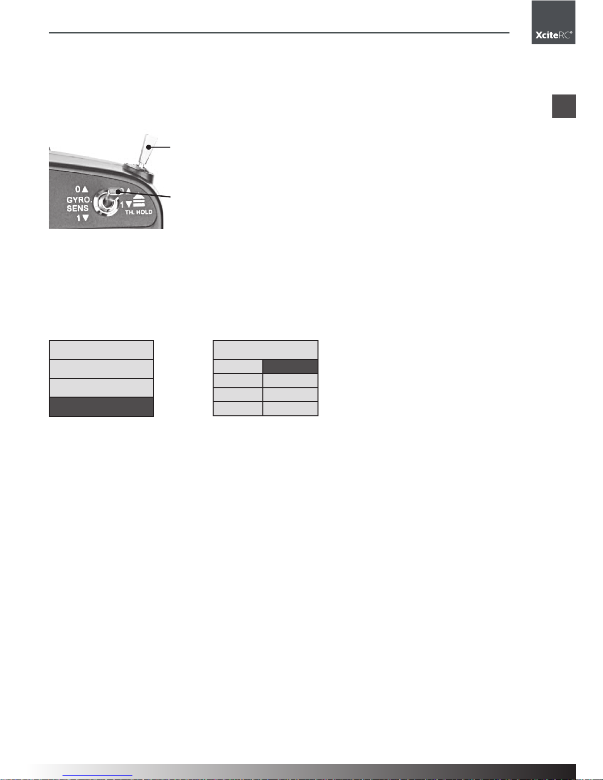
HV.PT
IDLE-Schalter
(Heli.) A/E/R DR
(Aile, Elev, Rudd)
LED
Digitale Ttrimmung
Linker Kreuzknüppel
Tragriemen-Öse
Digitale Trimmung
Ein-Schalter
LCD-Anzeige
Up
Down
Exit
Griff
HV.TH
TH.Hold (Heli)
CH6 (Flugmodell)
Kreisel-Empf. (Heli)
CH5 (Flugmodell)
Digitale Trimmung
Rechter Kreuzknüppel
Digitale Trimmung
INC (Timer-Start)
Ladebuchse
DEC (Timer Reset)
ENTER
Binden des Empfängers
Die Vorgehensweise:
• Schalten Sie den Sender ein und danach verbinden Sie den Empfänger mit dem Akku, während Sie den
„BIND“-Knopf solange drücken, bis die Anzeige auf Grün geht, was bedeutet, dass das Binden erfolgreich war.
• Zu beachten: Sender und Empfänger sollten dabei voneinander maximal einen Meter entfernt sein und in
einem Umkreis von 10 Metern darf sich kein ähnliches Gerät befinden.
• Wenn die Anzeige blinkt, bedeutet das, dass das Binden nicht erfolgt ist. Wiederholen Sie die geschilderten Schritte.

7
50500000 Sender X-6S
4,8 V F100
TIMER
00.00
FUN.
SYS.
.
THRO HOLD
4,8 V F100
TIMER
00.00
FUN.
SYS.
.
IDLE ON
4,8 V F100
TIMER
00.00
FUN.
SYS.
.
TH.HOLD
IDLE
45
45
Grundlegende Funktionen
DE
Grundlegende Funktionen
• Pitch Neutraltrimmung
• 6 Standard-Kanalausgänge und unterstützt 2,4-GHz-Systeme
• Unterstützt 3D-Flugmodus: Normalflug, Leerlauf 1 Flug und Leerlauf 2 Flug (im IDLE-Modus)
• D/R für Querruder, Höhe und Ruder
• Drossel Halte-Funktion
• Kreisel Empfindlichkeits-Anpassung
• Neutrale Stellung für alle Kanäle
• Reverse und Servo-Wegeinstellung für alle Kanäle
• Speicher für 6 Modelle
• Die Anzeige-LED blinkt, wenn die Spannung unter 4,0 V sinkt
Die Grundanzeige
Spannung
Funktion
System
Modellspeicher
Timer
LED- und Funktionsanzeige
Betriebsspannungs-LED ist blau
Betriebsanzeige LED
• Diese leuchtet im normalen Betrieb blau.
• Wenn die Spannung unter 4,0 V sinkt, beginnt die LED zu blinken. Stellen Sie den Betrieb ein und wechseln Sie die Batterie.
Zu Beachten:
Wenn „HOLD ON“ nach dem Einschalten auf der LCD-Anzeige zu sehen ist, schalten Sie den TH.HOLDSchalter in die Position 0. Andernfalls ist ein Betrieb nicht möglich.
Wenn „IDLE ON“ nach dem Einschalten auf der LCD-Anzeige zu sehen ist, schalten Sie den IDLE-Schalter
in die Position N. Andernfalls ist ein Betrieb nicht möglich.
Wenn „THRO STICK“ nach dem Einschalten auf der LCD-Anzeige zu sehen ist, bewegen Sie den Gasknüppel in die vordere Endstellung. Andernfalls ist ein Betrieb nicht möglich.

8
50500000 Sender X-6S
DE
Menüs
Menüs
Funktionsmenü (FUN.MENU):
Heli Flug V-Leitwerk Delta
D/R D/R D/R D/R
SUB.TRIM SUB.TRIM SUB.TRIM SUB.TRIM
TRAVEL TRAVEL TRAVEL TRAVEL
CH.REV CH.REV CH.REV CH.REV
SWASH.MIX MONITOR MONITOR MONITOR
GYRO.SEN V-TAIL DELTA-MIX
THRO.CURV
MONITOR
PIT.CURV
THRO.HOLD
System-Menü (SYS.MENU):
Heli Flug V-Leitw. Delta
MODEL.SET MODEL.SET MODEL.SET MODEL.SET
PLANETYPE PLANETYPE PLANETYPE PLANETYPE
STICKMODE STICKMODE STICKMODE STICKMODE
STICK.ADJ STICK.ADJ STICK.ADJ STICK.ADJ
TRAINER TRAINER TRAINER TRAINER
• MODEL.SET: Damit können Sie die Parameter des Modells einstellen, Name ändern, speichern oder
zurück auf die Werkseinstellungen setzen.
• PLANE TYPE: 4 Arten von Modellen sind auswählbar: Helikopter, Flächenmodell, V-Leitwerk und Delta.
• STICK MODE: Der Modus kann eingestellt werden: Mode 1 (Drossel rechts), Mode 2 (Drossel links), Mode
3 und Mode 4
• STICK ADJ: Die Mittelstellung der 4 Proportional-Kanäle der Kreuzknüppel wird mit dieser Funktion automatisch angepasst.
• TRAINER: Dieser Menüpunkt kann dazu benutzt werden, die Einstellungen zu simulieren.
Navigation in den Menüs
Mit den Tasten Down und Up wählen Sie in der Anzeige nach dem Einschalten das Funktions- oder das
System-Menü aus (grau hinterlegt). In den Menüs selber können Sie mit der Up oder Down-Taste die gewünschte Funktion auswählen (ist dann grau hinterlegt). Es werden dabei nicht immer alle Menüfunktionen
angezeigt. Mit der Up oder Down-Taste werden diese sichtbar, wenn man über die Grenzen der Anzeige
hinausgeht. Mit der ENTER-Taste wird eine Funktion dann aufgerufen. Die EXIT-Taste führt jeweils eine Ebene
zurück.
Voreingestellte Modellspeicher
Flybarless 200 Trainer: FB70
Flybarless 200 3D: FB80
Flybarless 245 Trainer: FB90
Flybarless 245 3D: F100
Quadrocopter HotBee 3D: F120
Paracopter: MOD6

9
50500000 Sender X-6S
345
SYS.MENU
MODEL SET
PLANE TYPE
STICK MODE
4,8 V F100
TIMER
00.00
FUN.
SYS.
.
SYS.MENU
STICK ADJ.
TRAINER
TIMER SET
345
MODEL M001
RENAME
SAVE AS
RECOVER
RENAME M001
RENAME
SAVE AS
RECCVER
0 1 2 3 4 5 6 7 8 9
A B C D E F G H I J
K L M N O P Q R S T
U V W X Y Z < >
MODEL M001
RENAME
SAVE AS
RECCVER
SAVE TO:
M001
MODEL M001
RENAME
SAVE AS
RECCVER
RECOVER..
SYS.MENU
MODEL SET
PLANE TYPE
STICK MODE
MODULATE
HELIC PLANE
V-TAI DELTA
STICK MODE
MODE 1
RUELAI
TH
STICK MODE
MODE 2
RUTHAI
EL
STICK MODE
MODE 3
AIELRU
TH
STICK MODE
MODE 4
AITHRU
EL
SYS.MENU
STICK ADJ.
TRAINER
TIMER SET
ADJUST?
NO
SYS.MENU
STICK ADJ.
TRAINER
TIMER SET
ADJUST
SYS.MENU
S TICK ADJ.
TRAINER
TIMER SET
TRAINER
NORMAL
SYS.MENU
STICK ADJ.
TRAINER
TIMER SET
TRAINER
TRAINER
DE
System-Menü
System-Menü Übersicht
MODEL SET
PLANE TYPE
STICK Mode
STICK ADJ
TRAINER

10
50500000 Sender X-6S
ENTER
345
INC/DEC
345
SYS.MENU
MODEL SET
PLANE TYPE
STICK MODE
MODEL F100
RENAME
SAVE AS
RECOVER
MODEL M001
RENAME
SAVE AS
RECOVER
MODEL M001
RENAME
SAVE AS
RECOVER
RENAME M001
RENAME
SAVE AS
RECCVER
0 1 2 3 4 5 6 7 8 9
A B C D E F G H I J
K L M N O P Q R S T
U V W X Y Z
< >
ENTER
345
STICK
RU EL
MODEL M001
RENAME
SAVE AS
RECOVER
MODEL M001
RENAME
SAVE AS
RECCVER
SAVE TO:
M001
ENTER
345
DE
System-Menü
MODEL SET
Aufruf eines Modellspeichers:
• Drücken Sie „Down“ um das SYS MENU anzuwählen und danach drücken Sie ENTER, um es aufzurufen.
• Wählen Sie nun mit Up und Down MODEL SET an (grau hinterlegt). Mit der ENTER-Taste gelangen Sie
in das Menü.
• Mit den Tasten Up und Down wählen Sie oben rechts den Modellnamen an (bis dieser grau hinterlegt ist).
Drücken Sie nun INC oder DEC, um den gewünschten Speicherplatz auszuwählen. Die Grundeinstellungen sind Mod1, Mod2, Mod3, Mod4, Mod5 und Mod6.
• Drücken Sie ENTER um den ausgewählten Modellspeicherplatz zu bestätigen. Andernfalls erfolgt keine
Umstellung. Es erscheint nun die Meldung „Reload“ womit die Werte des gewählten Modells übernommen werden. Die EXIT-Taste führt auf die vorherige Menüebene zurück.
Bemerkung: Wenn Ihre Auswahl erfolgreich war, wird der Modellname in der Hauptanzeige entsprechen
geändert.
Bitte beachten: Alle Ihre Einstellungen werden in dem vorher ausgewählten Modellspeicher gespeichert.
Name des Modells ändern:
• Drücken Sie „Down“ um das SYS MENU anzuwählen und danach drücken Sie ENTER, um es aufzurufen.
• Wählen Sie nun mit Up und Down MODEL SET an (grau hinterlegt). Mit der ENTER-Taste gelangen Sie
in das Menü.
• Drücken Sie „Up“ oder „Down“, um die RENAME-Funktion auszuwählen (grau hinterlegt). Drücken Sie
nun ENTER, um in den RENAME-Menüpunkt zu gelangen.
• Bewegen Sie den EL/RU-Kreuzknüppel, um Buchstaben oder Ziffern auszuwählen und so den Speicherplatz neu zu benennen.
• Drücken Sie ENTER um die ausgewählten Buchstaben und Zahlen zu bestätigen. Andernfalls erfolgt
keine Änderung.
Achtung: Wenn keine Buchstaben in linker Richtung ausgewählt werden können, müssen Sie STICK ADJ
ausführen.
Bitte beachten: Wenn der Cursor auf < oder > steht, kann ENTER gedrückt werden, um den Buchstaben
des Namens zu überspringen.
Speichern in einen anderen Modellspeicher:
• Drücken Sie „Down“ um das SYS MENU anzuwählen und danach drücken Sie ENTER, um es aufzurufen.
• Wählen Sie nun mit Up und Down MODEL SET an (grau hinterlegt). Mit der ENTER-Taste gelangen Sie
in das Menü.

11
50500000 Sender X-6S
MODEL M001
RENAME
SAVE AS
RECOVER
MODEL M001
RENAME
SAVE AS
RECCVER
RECOVER..
ENTER
345
SYS.MENU
MODEL SET
PLANE TYPE
STICK MODE
SYS.MENU
MODEL SET
PLANE TYPE
STICK MODE
MODULATE
HELIC PLANE
V-TAI DELTA
ENTER
345
STICK
RUDD
STICK MODE
MODE 1
RUELAI
TH
STICK MODE
MODE 2
RUTHAI
EL
STICK MODE
MODE 3
AIELRU
TH
STICK MODE
MODE 4
AITHRU
EL
DE
System-Menü
• Drücken Sie „Up“ oder „Down“, um die SAVE AS-Funktion auszuwählen (grau hinterlegt). Drücken Sie
nun ENTER, um in den SAVE AS-Menüpunkt zu gelangen.
• Drücken Sie „Up“ oder „Down“ um die Nummer zu bestimmen, in der das Modell gespeichert werden
soll. Drücken Sie ENTER, um die Speicherung durchzuführen. Dieser Vorgang kann für mehrere Modelle
nacheinander durchgeführt werden. Drücken Sie Exit, um den Menüpunkt zu verlassen.
Anmerkung: Die gespeicherten Werte überschreiben die des bisherigen Modells. Also verwenden Sie diese
Funktion mit Vorsicht.
Zurückstellen auf die Werkseinstellungen:
• Drücken Sie „Down“ um das SYS MENU anzuwählen und danach drücken Sie ENTER, um es aufzurufen.
• Wählen Sie nun mit Up und Down MODEL SET an (grau hinterlegt). Mit der ENTER-Taste gelangen Sie
in das Menü.
• Drücken Sie „Up“ oder „Down“, um die RECOVER-Funktion auszuwählen (grau hinterlegt). Drücken Sie
nun ENTER, um auf die Werkseinstellungen zurückzusetzen. Drücken Sie Exit, um diesen Menüpunkt zu
verlassen.
Anmerkung: Diese Rückstellung löscht alle Einstellungen des gewählten Modells. Wenden Sie diese Funktion
nur mit Vorsicht an.
Plane Type
Auswahl des Modelltyps:
• Drücken Sie „Down“ um das SYS MENU auszuwählen. Drücken Sie nun ENTER, um die Funktion aufzurufen.
• Drücken Sie „Up“ oder „Down“, um PLANE TYPE anzuwählen (grau hinterlegt). Drücken Sie nun ENTER,
um in den Menüpunkt zu gelangen.
• Nun erscheint eine Dialogbox. Drücken Sie Up oder Down, um Heli, Plane, V-Tail oder Delta auszuwählen.
Drücken Sie ENTER, um die Auswahl zu bestätigen und den Menüpunkt zu verlassen.
Stick Mode
Auswahl des Modus:
• Drücken Sie „Down“ um das SYS MENU auszuwählen. Drücken Sie nun ENTER, um die Funktion aufzurufen.
• Drücken Sie „Up“ oder „Down“, um STICK MODE anzuwählen (grau hinterlegt). Drücken Sie nun ENTER,
um in den Menüpunkt zu gelangen.

12
50500000 Sender X-6S
SYS.MENU
STICK ADJ.
TRAINER
TIMER SET
SYS.MENU
STICK ADJ.
TRAINER
TIMER SET
ADJUST?
NO
SYS.MENU
STICK ADJ.
TRAINER
TIMER SET
ADJUST
ENTER
345
ENTER
345
SYS.MENU
S TICK ADJ.
TRAINER
TIMER SET
TRAINER
NORMAL
SYS.MENU
STICK ADJ.
TRAINER
TIMER SET
TRAINER
TRAINER
SYS.MENU
S TICK ADJ.
TRAINER
TIMER SET
ENTER
345
ENTER
345
DE
System-Menü
• Drücken Sie nun Up oder Down, um Model 1 (Drossel rechts), Mode 2 (Drossel links), Mode 3 oder Mode
4 auszuwählen. Drücken Sie ENTER, um die Auswahl zu bestätigen. Mit Exit verlassen Sie diesen Menüpunkt.
Anmerkung: Diese Funktion ändert die Zuordnung aller 4 Proportional-Kanäle der Kreuzknüppel. Damit werden AILE, ELEV, THRO Und RUDD zugeordnet. Wenn der Stick-Modus geändert wird, wird auch die Menüreihenfolge der Knüppel AI und El geändert. Bitte beachten Sie die Unterschiede.
Stick Adj
Neutrale Position der Knüppel setzen:
• Drücken Sie „Down“ um das SYS MENU anzuwählen und danach drücken Sie ENTER, um es aufzurufen.
• Wählen Sie nun mit Up und Down STICK ADJ an (grau hinterlegt). Mit der ENTER-Taste gelangen Sie in
das Menü.
• Drücken Sie „Down“, um ADJUST YES auszuwählen (grau hinterlegt). Mit der Up-Taste können Sie das
wieder auf ADJUST NO umstellen. Drücken Sie nun ENTER, wird die Mittelstellung der Knüppel neu bestimmt. Der Abschluss der Funktion wird mit einem kurzen Beep angezeigt.
• Bevor Sie diese Funktion ausführen, müssen die Kreuzknüppel wie auch die digitalen Trimmungen auf
Mittelstellung eingestellt werden.
• Drücken Sie Exit, um zu speichern und die Funktion zu verlassen.
Trainer
Trainer-Auswahl:
• Drücken Sie „Down“ um das SYS MENU anzuwählen und danach drücken Sie ENTER, um es aufzurufen.
• Wählen Sie nun mit Up und Down TRAINER an (grau hinterlegt). Mit der ENTER-Taste gelangen Sie in
das Menü.
• Drücken Sie „Up“ oder „Down“, um die Trainer-Funktion Normal oder Trainer auszuwählen (grau hinterlegt). Drücken Sie nun ENTER, um die Funktion auszuführen.
Normal = Normaler Flugmodus
Trainer = Software-Simulation eines Fluges
Bitte beachten:
Diese Funktion kann in einem Computer eines Flug simulieren. Dazu werden aber ein spezielles Kabel und
eine Simulations-Software für den Computer benötigt.
Der Trainer-Anschluss auf der Computer-Rückseite darf nicht mit irgendwelchen elektronischen Geräten oder
anderen Sendern verbunden werden, das kann zu Schäden an den Geräten führen.
Die Schnittstelle ermöglicht keine Lehrer-Schüler-Funktion. Sie dient ausschließlich für den Anschluss von
Simulations-Software.

13
50500000 Sender X-6S
SYS.MENU
STICK ADJ.
TRAINER
TIMER SET
TIMER SET
00: 00
ENTER
345
DE
System-Menü
Timer Set
• Drücken Sie „Down“ um das SYS MENU anzuwählen und danach drücken Sie ENTER, um es aufzurufen.
• Wählen Sie nun mit Up und Down TIMER SET an (grau hinterlegt). Mit der ENTER-Taste gelangen Sie in
das Menü.
• Mit der DEC und INC-Taste stellen Sie den Wert für den Timer im Minuten:Sekunden-Format ein. Mit Up
und Down schalten Sie zwischen der Eingabe der Minuten und Sekunden um. Mit der ENTER-Taste bestätigen Sie die Eingabe. Mit EXIT verlassen Sie diese Funktion.
• Durch Drücken von INC im Normalbetrieb wird der Timer gestartet.
Bitte beachten: 20 Sekunden vor Ablauf des Timers wird jede Sekunde ein Alarm-Beep ausgegeben. Durch
Drücken von DEC wird der Timer gestoppt und auf 0 zurückgesetzt.

14
50500000 Sender X-6S
4,8 V F100
TIMER
00.00
FUN.
SYS.
.
FUN.MENU
D/R
SUB.TRIM
TRAVEL
FUN.MENU
CH.REV
SWASH.MIX
GYRO.SENE
FUN.MENU
THRO.CURV
MONITOR
PIT.CURV
FUN.MENU
THRO.HOLD
ENTER
345
DR AILE0
RENAME
SAVE AS
RECCVER
H 100
I 0
O 0
L 100
SUB.TRIM
AILE 0
ELEV 0
THRO 0
SUB.TRIM
RUDD 0
GEAR 0
PITH 0
TRAVEL
AILE 100 100
ELEV 100 100
THRO 100 100
TRAVEL
RUDD 100 100
GEAR 100 100
PITH 100 100
DR AILE1
RENAME
SAVE AS
RECCVER
H 100
I 0
O 0
L 100
REV. SW
CH 1 2 3 4 5 6
REV
NOR
DE
Funktions-Menü
Funktions-Menü (Heli)
D/R
SUB TRIM
TRAVEL
CH REV

15
50500000 Sender X-6S
SQASH.MIX
AILE -50
PITH -50
ELEV -50
GYRO.SENS
POS0 -100
POS1 100
THRO. CURV
NOR
I 50
O 50
L 100
THRO. CURV
IDLE 0
I 20
O 20
H 75
THRO. CURV
IDLE 1
I 20
O 20
H 3
PIT. CURV
IDLE 0
I 20
O 20
H 0
PIT. CURV
IDLE 1
I 20
O 20
H 75
PIT. CURV
NOR
I 0
O 0
L 0
THRO. HOLD
SW ON
VALUE -20
1
2
3
4
5
6
DE
Funktions-Menü
SWASH MIX
GYRO SENS
THRO CRUV
MONITOR
PIT CURVE
THRO HOLD

16
50500000 Sender X-6S
FUN.MENU
D/R
SUB.TRIM
TRAVEL
DR AILE0
RENAME
SAVE AS
RECCVER
H 100
I 0
O 0
L 100
DR AILE1
RENAME
SAVE AS
RECCVER
H 100
I 0
O 0
L 100
DR AILE0
RENAME
SAVE AS
RECCVER
H 100
I 0
O 0
L 100
A/E/R DR SW
POS0/POS1
A/E/R DR SW
DR ELEV1
RENAME
SAVE AS
RECCVER
H 100
I 0
O 0
L 100
A/E/R DR SW
POS0/POS1
A/E/R DR SW
DE
Funktions-Menü
D/R
D/R (Dual-Rate) für AILE (Querruder)
• Drücken Sie „Up“ um das FUNC MENU anzuwählen und danach drücken Sie ENTER, um es aufzurufen.
• Wählen Sie nun mit Up und Down D/R an (grau hinterlegt). Mit der ENTER-Taste gelangen Sie in das
Menü.
• Mit der ENTER-Taste können Sie AILE (Querruder), ELEV (Höhenruder) oder RUDD (Seitenruder) auswählen.
• Mit dem Schalter A/E/R DR bestimmen Sie, welcher Wert geändert wird, AILE0 oder AILE1
• Mit Up und Down wählen Sie den Wert H oder L, der geändert wird (jeweils grau hinterlegt). Die Kurve in
der Anzeige ändert sich entsprechend.
• Mit DEC und INC stellen Sie den Wert ein.
• Mit Exit verlassen Sie diesen Menüpunkt.
Wenn der Schalter A/E/R DR in der Position 0 steht, werden die Werte von AILE0 geändert.
Wenn der Schalter A/E/R DR in der Position 1 steht, werden die Werte von AILE1 geändert.
D/R (Dual-Rate) für ELEV (Höhenruder)
• Drücken Sie „Up“ um das FUNC MENU anzuwählen und danach drücken Sie ENTER, um es aufzurufen.
• Wählen Sie nun mit Up und Down D/R an (grau hinterlegt). Mit der ENTER-Taste gelangen Sie in das
Menü.
• Drücken Sie nun noch mal ENTER, um ELEV auszuwählen.
• Mit dem Schalter A/E/R DR bestimmen Sie, welcher Wert geändert wird, ELEV0 oder ELEV1
• Mit Up und Down wählen Sie den Wert H oder L, der geändert wird (jeweils grau hinterlegt). Die Kurve in
der Anzeige ändert sich entsprechend.
• Mit DEC und INC stellen Sie den Wert ein.
• Mit Exit verlassen Sie diesen Menüpunkt.
Wenn der Schalter A/E/R DR in der Position 0 steht, werden die Werte von ELEV0 geändert.
Wenn der Schalter A/E/R DR in der Position 1 steht, werden die Werte von ELEV1 geändert.

17
50500000 Sender X-6S
DR RUDD0
RENAME
SAVE AS
RECCVER
H 100
I 0
O 0
L 100
A/E/R DR SW
POS0/POS1
A/E/R DR SW
FUN.MENU
D/R
SUB.TRIM
TRAVEL
SUB.TRIM
AILE 0
ELEV 0
THRO 0
SUB.TRIM
RUDD 0
GEAR 0
PITH 0
TRAVEL
AILE 100 100
ELEV 100 100
THRO 100 100
TRAVEL
RUDD 100 100
GEAR 100 100
PITH 100 100
ENTER
345
IUP/DOWN
345
FUN.MENU
D/R
SUB.TRIM
TRAVEL
ENTER
345
IUP/DOWN
345
STICK
RUDD
DE
Funktions-Menü
D/R (Dual-Rate) für RUDD (Seitenruder)
• Drücken Sie „Up“ um das FUNC MENU anzuwählen und danach drücken Sie ENTER, um es aufzurufen.
• Wählen Sie nun mit Up und Down D/R an (grau hinterlegt). Mit der ENTER-Taste gelangen Sie in das
Menü.
• Drücken Sie nun noch zweimal ENTER, um RUDD auszuwählen.
• Mit dem Schalter A/E/R DR bestimmen Sie, welcher Wert geändert wird, RUDD0 oder RUDD1
• Mit Up und Down wählen Sie den Wert H oder L, der geändert wird (jeweils grau hinterlegt). Die Kurve in
der Anzeige ändert sich entsprechend.
• Mit DEC und INC stellen Sie den Wert ein.
• Mit Exit verlassen Sie diesen Menüpunkt.
Wenn der Schalter A/E/R DR in der Position 0 steht, werden die Werte von RUDD0 geändert.
Wenn der Schalter A/E/R DR in der Position 1 steht, werden die Werte von RUDD1 geändert.
SUB Trim
Einstellen der Servo-Mittelstellung (SUB.TRIM):
• Drücken Sie „Up“ um das FUNC MENU anzuwählen und danach drücken Sie ENTER, um es aufzurufen.
• Wählen Sie nun mit Up und Down SUB.TRIM an (grau hinterlegt). Mit der ENTER-Taste gelangen Sie in
das Menü.
• Wählen Sie mit Up und Down AILE, ELEV, THRO, RUDD, GEAR oder PITCH an.
• Mit INC und DEC ändern sie den eingestellten Wert.
• Mit Exit verlassen Sie diesen Menüpunkt.
Travel
Einstellen der Servo-Endausschläge (TRAVEL):
• Drücken Sie „Up“ um das FUNC MENU anzuwählen und danach drücken
Sie ENTER, um es aufzurufen.
• Wählen Sie nun mit Up und Down TRAVEL an (grau hinterlegt). Mit der
ENTER-Taste gelangen Sie in das Menü.
• Wählen Sie mit Up und Down AILE, ELEV, THRO, RUDD, GEAR oder
PITCH an. Den rechten oder linken Wert wählen Sie durch Betätigen des
Seitenruder-Knüppels aus.
• Mit INC und DEC ändern sie den eingestellten Wert.
• Mit Exit verlassen Sie diesen Menüpunkt.

18
50500000 Sender X-6S
ENTER
345
IUP/DOWN
345
FUN.MENU
CH.REV
SWASH.MIX
GYRO.SENE
REV. SW
CH 1 2 3 4 5 6
REV
NOR
REV. SW
CH 1 2 3 4 5 6
REV
NOR
FUN.MENU
CH.REV
SWASH.MIX
GYRO.SENE
SQASH.MIX
AILE -50
PITH -50
ELEV -50
SQASH.MIX
AILE -30
PITH -50
ELEV 80
ENTER
345
IUP/DOWN
345
FUN.MENU
CH.REV
SWASH.MIX
GYRO.SENE
GYRO.SENS
POS0 -100
POS1 100
GYRO SENS
POS0/POS1
GYRO SENS
ENTER
345
DE
Funktions-Menü
CH.Rev
Einstellung der Servo-Laufrichtung:
• Drücken Sie „Up“ um das FUNC MENU anzuwählen und danach drücken Sie ENTER, um es aufzurufen.
• Wählen Sie nun mit Up und Down CH.REV an (grau hinterlegt). Mit der ENTER-Taste gelangen Sie in das
Menü.
• Wählen Sie mit Up und Down den gewünschten Kanal an (1 bis 6) an. Die Laufrichtung ändern Sie mit
der INC und DEC-Taste.
• Mit Exit verlassen Sie diesen Menüpunkt.
Swash.Mix
Taumelscheiben-Mixer (nur für CCPM 3 Servos 120° Helikopter):
• Drücken Sie „Up“ um das FUNC MENU anzuwählen und danach drücken Sie ENTER, um es aufzurufen.
• Wählen Sie nun mit Up und Down SWASH.MIX an (grau hinterlegt). Mit der ENTER-Taste gelangen Sie
in das Menü.
• Wählen Sie mit Up und Down AILE, PITCH, ELEV an. Mit INC und DEC ändern sie den eingestellten Wert.
• Mit Exit speichern und verlassen Sie diesen Menüpunkt.
Gyro.Sens
Empfindlichkeit des Kreisels (Gyro sensitivity):
• Drücken Sie „Up“ um das FUNC MENU anzuwählen und danach drücken Sie ENTER, um es aufzurufen.
• Wählen Sie nun mit Up und Down GYRO.SENS an (grau hinterlegt). Mit der ENTER-Taste gelangen Sie
in das Menü.
• Mit dem Schalter GYRO SENS bestimmen Sie, welcher Wert geändert wird, POS0 oder POS1. Wenn
der GYRO SENS-Schalter in der Position 0 steht, ist dieser Wert grau hinterlegt und sie können diesen
ändern. Wenn der GYRO SENS-Schalter in der Position 1 steht, ist dieser Wert grau hinterlegt und sie
können diesen ändern.
• Wert wählen Sie durch Betätigen des Seitenruder-Knüppels aus.
• Mit INC und DEC ändern sie den eingestellten Wert.
• Mit Exit speichern und verlassen Sie diesen Menüpunkt.

19
50500000 Sender X-6S
FUN.MENU
THRO.CURV
MONITOR
PIT.CURV
THRO. CURV
NOR
I 50
O 50
L 100
THRO. CURV
IDLE 0
I 20
O 20
H 75
THRO. CURV
IDLE 1
I 20
O 20
H 3
IDLE SW
NOR/POS0/
POS1
IDLE SW
ENTER
345
FUN.MENU
THRO.CURV
MONITOR
PIT.CURV
ENTER
345
1
2
3
4
5
6
DE
Funktions-Menü
Thro.Curve
Gas-Kurve (Throttle curve):
• Drücken Sie „Up“ um das FUNC
MENU anzuwählen und danach
drücken Sie ENTER, um es aufzurufen.
• Wählen Sie nun mit Up und Down
THRO.CURV an (grau hinterlegt).
Mit der ENTER-Taste gelangen Sie in das Menü.
• Wählen Sie mit Up und Down den gewünschten Punkt an (L, 1, 2, 3 und H) an, der im untersten Feld
angezeigt wird. Den jeweiligen Wert ändern Sie mit der INC und DEC-Taste.
• Mit dem Schalter IDLE können Sie drei Kurven anwählen, NOR, IDLE0 und IDLE1.
• Mit Exit speichern und verlassen Sie diesen Menüpunkt.
Anmerkung: Der Sender kann 3 verschiedene Gas-Kurven speichern. Dies ist sinnvoll für 3D-Flugfiguren.
Fragen Sie hier erfahrene Piloten um Ratschläge.
Monitor
Monitor-System:
• Drücken Sie „Up“ um das FUNC MENU anzuwählen und danach drücken Sie ENTER, um es aufzurufen.
• Wählen Sie nun mit Up und Down MONITOR an (grau hinterlegt). Mit der ENTER-Taste gelangen Sie in
das Menü.
• Wenn Sie jetzt die Steuerknüppel oder Kanal-Schalter betätigen, ändern sich die Kanal-Anzeigen gemäß
den Servobewegungen. Die Funktion wurde eingebaut, um die Einstellungen des Senders sichtbar zu
machen.
• Mit Exit verlassen Sie diesen Menüpunkt.
Anmerkung: Die Funktion hilft bei der Einstellung des Senders, der Trimmung der einzelnen Kanäle und dient
zur Überprüfung der Kanäle.

20
50500000 Sender X-6S
FUN.MENU
THRO.CURV
MONITOR
PIT.CURV
PIT. CURV
IDLE 0
I 20
O 20
H 0
PIT. CURV
IDLE 1
I 20
O 20
H 75
PIT. CURV
NOR
I 0
O 0
L 0
IDLE SW
NOR/POS0/
POS1
IDLE SW
ENTER
345
FUN.MENU
THRO.HOLD
THRO. HOLD
SW ON
VALUE -20
TH HOLD
POS0/POS1
TH HOLD
ENTER
345
DE
Funktions-Menü
Pit.Curve
Pitch Kurve (Pitch curve):
• Drücken Sie „Up“ um das FUNC
MENU anzuwählen und danach
drücken Sie ENTER, um es aufzurufen.
• Wählen Sie nun mit Up und
Down PIT.CURV an (grau hinterlegt). Mit der ENTER-Taste gelangen Sie in das Menü.
• Wählen Sie mit Up und Down den gewünschten Punkt an (L, 1, 2, 3 und H) an, der im untersten Feld
angezeigt wird. Den jeweiligen Wert ändern Sie mit der INC und DEC-Taste.
• Mit dem Schalter IDLE können Sie drei Kurven anwählen, NOR, IDLE0 und IDLE1.
• Mit Exit speichern und verlassen Sie diesen Menüpunkt.
Anmerkung: Der Sender kann 3 verschiedene Pitch-Kurven speichern. Die ist sinnvoll für 3D-Flugfiguren.
Fragen Sie hier erfahrene Piloten um Ratschläge.
Thro.Hold
Throttle hold:
• Drücken Sie „Up“ um das FUNC MENU anzuwählen und danach drücken Sie ENTER, um es aufzurufen.
• Wählen Sie nun mit Up und Down THRO.HOLD an (grau hinterlegt). Mit der ENTER-Taste gelangen Sie
in das Menü.
• Schalten Sie den TH.HOLD-Schalter in die gewünschte Position. Wenn dieser auf Position 0 steht, wird
im Display SW OFF angezeigt, in Position ist es SW ON.
• Den jeweiligen Wert (VALUE) ändern Sie mit der INC und DEC-Taste.
• Mit Exit speichern und verlassen Sie diesen Menüpunkt.
21
50500000 Sender X-6S
FUN.MENU
CH.REV
MONITOR
V-TAIL
V-TAIL
ELEV1 50
ELEV2 50
RUDD2 50
RUDD1 50
ENTER
345
DE
Funktions-Menü
Funktions-Menü für normale Flugmodelle
Dieses Menü beinhaltet die Funktionen D/R, SUB.TRIM, TRAVEL, CH.REV und MONITOR. Diese sind bereits
unter dem Helikopter Funktions-Menü beschrieben.
Einziehfahrwerk Kanal 5
Landeklappen Kanal 6
Funktionsmenü für V-Leitwerk
Dieses Menü beinhaltet die Funktionen D/R, SUB.TRIM, TRAVEL, CH.REV und MONITOR. Diese sind bereits
unter dem Helikopter Funktions-Menü beschrieben.
V-Tail
V-Leitwerk Mischer
• Drücken Sie „Up“ um das FUNC MENU anzuwählen und danach drücken Sie ENTER, um es aufzurufen.
• Wählen Sie nun mit Up und Down V-TAIL an (grau hinterlegt). Mit der ENTER-Taste gelangen Sie in das
Menü.
• Wählen Sie mit Up und Down ELEV1, ELEV2, RUDD2 oder RUDD1 an. Mit INC und DEC ändern sie den
eingestellten Wert.
• Mit Exit speichern und verlassen Sie diesen Menüpunkt.

22
50500000 Sender X-6S
FUN.MENU
CH.REV
MONITOR
DELTA-MIX
V-TAIL
AILE2 50
AILE1 50
ELEV1 50
ELEV2 50
ENTER
345
AILE
ELEV
PITCH
Vorne
DE
Einbau/Verbindungen
Funktionsmenü für Delta-Modelle
Dieses Menü beinhaltet die Funktionen D/R, SUB.TRIM, TRAVEL, CH.REV und MONITOR. Diese sind bereits
unter dem Helikopter Funktions-Menü beschrieben.
Delta-Mix
Delta-Mischer
• Drücken Sie „Up“ um das FUNC MENU anzuwählen und danach drücken Sie ENTER, um es aufzurufen.
• Wählen Sie nun mit Up und Down DELTA-MIX an (grau hinterlegt). Mit der ENTER-Taste gelangen Sie in
das Menü.
• Wählen Sie mit Up und Down AILE2, AILE1, ELEV1 oder, ELEV2 an. Mit INC und DEC ändern sie den
eingestellten Wert.
• Mit Exit speichern und verlassen Sie diesen Menüpunkt.
Helikopter Einbau/Verbindungen
Schalten Sie den Sender auf Helikopter um und benutzen Sie den Helikopter-Modus
Empfänger

23
50500000 Sender X-6S
DE
Einbau/Verbindungen
Flächenmodell Einbau/Verbindungen
Schalten Sie den Sender auf Flugmodell um und benutzen Sie den Flugmodell-Modus, keine Mischer wie
für normale Flugzeuge.
Empfänger Kanalzuordnungen:
CH1: AILE Querruder
CH2: ELEV Höhenruder
CH3: THRO Gas/Drossel
CH4: RUDD Seitenruder
CH5: GEAR Einziehfahrwerk
CH6: FLAP Landeklappen

24
50500000 Sender X-6S
DE
Einbau/Verbindungen
V-Leitwerk Einbau/Verbindungen
Sender Mischer Empfangskanal
Knüppel Kanal 2 Kanal 4
Höhenruder +50% -50%
Seitenruder -50% +50%
Schalten Sie den Sender auf V-TAIL um und benutzen Sie den V-Leitwerks-Modus, Hohen- und Seitenruder
wird gemischt, wie für V-Leitwerke üblich.
Empfänger Kanalzuordnungen:
CH1: AILE Querruder
CH2: ELEV Höhenruder
CH3: THRO Gas/Drossel
CH4: RUDD Seitenruder
CH5: AILE2 Querruder 2
Delta-Modell Einbau/Verbindungen
Sender Mischer Empfangskanal
Knüppel Kanal 1 Kanal 2 Kanal5
Querruder +50% +50% +50%
Höhenruder +50% -50% +50%
Schalten Sie den Sender auf DELTA um und benutzen Sie den Delta-Modell-Modus, Seiten- und Höhenruder
wird gemischt.
Empfänger Kanalzuordnungen:
CH1: AILE Querruder
CH2: ELEV Höhenruder
CH3: THRO Gas/Drossel
CH4: RUDD Seitenruder
CH5: AILE2 Querruder 2

25
50500000 Sender X-6S
DE
Einbau/Verbindungen
Technische Daten
Digital Proportional RC System
Typ X-6S
Anzeige LCD
Modulation GFSK
Kanäle 6
Frequenz 2,4 GHz
Stromverbrauch <150 mA
Abmessungen 200 x 185 x 105 mm

26
50500000 Sender X-6S
DE
Reparaturen
Reparaturen
Normaler Verschleiß und defekte Teile, die von einem Unfall herrühren, sind von der Gewährleistung ausgeschlossen. Dazu zählen insbesondere:
Bei Automodellen: abgefahrene Reifen, abgenutzte Antriebsteile und Zahnräder, oder auch verbogene/gebrochene Radaufhängungen, Chassis oder Karosserien
Bei Schiffsmodellen: beschädigte oder gebrochene Schiffsschrauben, abgerissene Decksaufbauten
Bei Flugmodellen: Beschädigungen durch unsachgemäßen Transport oder Absturz
Falls Sie bereits nach dem Öffnen der Verpackung ein Teil entdecken, das bezüglich Material oder Verarbeitung defekt ist, senden Sie es - bevor Sie es benutzt haben - an Ihren Fachhändler oder an uns zurück und
wir werden Ihnen Ersatz liefern.
In Problemfällen oder bei Fragen wenden Sie sich bitte an Ihren Fachhändler oder:
XciteRC Modellbau GmbH & Co. KG - Service, Autenbachstrasse 12, D-73035 Göppingen, Tel. +49 7161
40 799 50
Email: service@xciterc.de
Ersatzteile können Sie entweder im Fachhandel oder online unter http://www.XciteRC.de/ beziehen.

27
50500000 Sender X-6S
DE
Umweltschutz
Cd Hg Pb
Li-Po
HINWEISE ZUM UMWELTSCHUTZ
Das Symbol des durchgestrichenen Mülleimers auf dem Produkt bzw. Verpackung besagt, dass
dieses getrennt vom üblichen Hausmüll entsorgt werden muss. Damit sollen schädliche Auswirkungen auf die Umwelt und die menschliche Gesundheit bei der Entsorgung von Elektro- und
Elektronikaltgeräten vermieden und deren Wiederverwendung oder Verwertung ermöglicht werden.
Sie haben die Möglichkeit, Elektro- und Elektronikaltgeräte kostenfrei bei einer entsprechenden Sammelstelle
in Ihrer Nähe abzugeben. Bitte erkundigen Sie sich bei Ihrer Stadt oder Gemeinde über die zur Verfügung
stehenden Sammelstellen. Sie haben auch die Möglichkeit, alte Elektro- und Elektronikgeräte, die von uns
bezogen wurden, frei an uns zurückzusenden. Wir werden diese dann einer ordnungsgemäßen Verwertung
bzw. Wiederverwendung zuführen.
Eventuell enthaltene Batterien oder Akkus müssen aus dem Produkt entfernt werden und bei der entsprechenden Sammelstelle getrennt entsorgt werden.
Hinweise nach Batteriegesetz
Da wir Batterien und Akkus bzw. solche Geräte verkaufen, die Batterien und Akkus enthalten, sind wir nach
dem Batteriegesetz (BattG) verpflichtet, Sie auf Folgendes hinzuweisen:
Batterien und Akkus dürfen nicht im Hausmüll entsorgt werden, sondern Sie sind zur Rückgabe gebrauchter
Batterien und Akkus gesetzlich verpflichtet. Altbatterien können Schadstoffe enthalten, die bei nicht sachgemäßer Lagerung oder Entsorgung die Umwelt oder Ihre Gesundheit schädigen können. Batterien enthalten
aber auch wichtige Rohstoffe wie z.B. Eisen, Zink, Mangan oder Nickel und werden wieder verwertet.
Sie können die Batterien nach Gebrauch entweder ausreichend frankiert an uns zurücksenden:
XciteRC Modellbau GmbH & Co.KG
Autenbachstr. 12
D-73035 Göppingen
oder in unmittelbarer Nähe (z.B. im Handel oder in kommunalen Sammelstellen) unentgeltlich zurückgegeben. Die Abgabe in Verkaufsstellen ist dabei auf für Endnutzer für die Entsorgung übliche Mengen sowie
solche Altbatterien beschränkt, die der Vertreiber als Neubatterien in seinem Sortiment führt oder geführt hat.
Schadstoffhaltige Batterien sind mit einem Zeichen, eine durchgestrichene Mülltonne, und dem chemischen
Symbol des schadstoffhaltigem Schwermetalls versehen.
Diese durchgekreuzte Mülltonne bedeutet, dass Sie Batterien und Akkus nicht im Hausmüll entsorgen dürfen.
Unter diesen Zeichen finden Sie zusätzlich nachstehende Symbole mit folgender Bedeutung:
Cd = Cadmium
Pb = Blei
Hg = Quecksilber
Li = Lithium

28
50500000 Sender X-6S
Summary
Intended Usage ......................................................................................................................................29
Scope of delivery ....................................................................................................................................29
Explanation of Symbols ..........................................................................................................................29
Warnings and safety notes......................................................................................................................30
Handling precautions for batteries or rechargeable batteries ...................................................................31
Basic features .........................................................................................................................................33
Main function Interface ...........................................................................................................................33
LED displaying board function_...............................................................................................................33
Menu ......................................................................................................................................................34
Navigation ..............................................................................................................................................34
System menu introduction ......................................................................................................................35
Function menu Introduction (Hell) ............................................................................................................40
Function menu for fixed wing plane.........................................................................................................47
Delta mix function menu .........................................................................................................................48
Heli.Connection Diagram (3 Servos CCPM) ............................................................................................48
Airplane Connection Diagram .................................................................................................................49
V-Tail Connection Diagram ......................................................................................................................50
DELTA-MIX Connection Diagram ............................................................................................................50
Specifications .........................................................................................................................................51
Repairs ...................................................................................................................................................52
Environmental Protection Notes ..............................................................................................................53
Notes on battery law ..............................................................................................................................53
EN
Summary
Imprint
This manual is a publication of
XciteRC Modellbau GmbH & Co. KG
Autenbachstrasse 12
D-73035 Göppingen
Phone: +49 7161 40 799 0
Fax: +49 7161 40 799 99
E-mail: info@xciterc.de
Web: www.XciteRC.de
All rights including translation. Reproductions of any kind, such as photocopying, microfilming or storage in electronic data
processing equipment, without the written permission of the publisher. Reproduction in whole or part, is prohibited.
This manual corresponds to the technical status of the product at time of printing, changes in technology and equipment
reserved. Text and illustrations of this manual, no claims can be derived.
NO LIABILITY FOR PRINTING ERROR! SUBJECT TO CHANGE!
The latest version of this manual can be found on the Internet at www.XciteRC.de
© Copyright 2013 by XciteRC-Modellbau GmbH & Co. KG

29
50500000 Sender X-6S
EN
Intended Usage
Thank you for purchasing the XciteRC transmitter X-6S. This manual contains important instructions for
operating your new model. Therefore, please read all instructions in this manual thoroughly before
using the model, so that you can operate your model safely.
All company and product names mentioned are trademarks of their respective owners.
All rights reserved.
Intended Usage
This remote control is intended for the use in radio-controlled models which are not man-carrying only, any
other use is not permitted. For any improper use outside of these conditions we can not give any warranty.
The product is not a toy and not suitable for children under 14 years of age, by children under 14 years the
maintenance and operation of the model must be supervised by an adult.
Read and observe all warnings and safety instructions in this manual and on the packaging before
operating!
This manual is part of this product. It contains important information for handling this product. Keep the
manual for future reference and also it must be strictly kept and passed on the subsequent sale of
the transmitter to the buyer. Failure to follow the operating instructions and the safety instructions
may invalidate the warranty.
Scope of delivery
Transmitter X-6S
Required accessories
Suitable receiver
Explanation of Symbols
WARNING: These instructions must be strictly observed by the operator! Failure to follow
these instructions may interfere with the safe function. These notes are also for your own
safety and that of other people!
ATTENTION: this information must be observed by the operator! Failure to follow these in-
structions can damage whatsoever, warranties power loss, etc. have resulted.
Information or advice, by which a smooth operation is ensured.
Instructions for care and maintenance to ensure a long shelf life of the product.

30
50500000 Sender X-6S
EN
Warnings and safety notes
Warnings and safety notes
The following safety instructions must be strictly observed. For property damage, personal injury or consequential damage caused by improper use or non-observance of the safety instructions the XciteRC Modellbau GmbH & Co. KG accepts no liability. In these cases, the warranty becomes void.
Move your model always with the maximum caution and responsibility, otherwise it may cause damage to
other property or even physical injury. We therefore recommend to secure the operation with a third party
liability insurance. If you already have a liability insurance policy, check before start-up the model, whether
radio-controlled models are covered by a corresponding amount.
• The product contains small parts that can cause injury if swallowed, and must therefore be kept
away from children under 3 years.
• The product is not a toy and not suitable for children under 14 years.
• The operation of radio-controlled models requires practice. In the beginning operate your new model
therefore with extra caution and familiarize yourself with the response to your commands.
• WARNING: The safe operation requires concentration and quick reaction. Do not operate your
model if you are tired or under the influence of drugs or alcohol – risk of accident and injury!
• WARNING: not to endanger people or animals - Accident and injury! Always pay attention to
sufficient distance and fly or drive never in the direction to people.
• This remote control may only be operated within the temperature range between about -10 ° and + 50
° C.
• WARNING: The control is done via radio signals, which can be influenced by the environment. This
may cause a suddenly loss of control of your model. Operate your model therefore only with sufficient light
within line of sight and in an open area, away from cars, traffic and people – risk of accident and injury!
• Do not operate your model during a thunder storm or near radio towers or power lines.
• Radio remote controlled models may not be operated at any public space by implication (streets, roads,
squares or lakes). Before operation please ask where the operation is allowed. This also applies to private
property, here the consent of the owner is required.
• WARNING: Keep your fingers or loose clothing or hair away from the rotating parts or wheels - risk
of injury!
• Always switch on the transmitter first, then the model. NOTE: during the operation of the transmitter
must remain switched on!
• Before each operation perform a range test on the ground by moving all sticks and note the correct reac-
tion of your model.
ATTENTION: If the reaction in this test is not correct, do not operate - risk of
accident and injury!
• Never operate your model with low transmitter batteries, because this reduces the range of your model
dramatically.
• If the drive battery is empty, the model first slow down until it no longer reacts properly to your commands.
Stop the operation and change the drive battery or charge it again.
• Pay attention to the instructions and warnings for this and any other equipment used by you (chargers,
rechargeable battery packs, etc.).
• WARNING: Keep packaging material, small parts, chemicals and electrical components away from
children – risk of accident and injury!
• ATTENTION: Do not drive against obstacles that the model cannot overcome, and stay on full
throttle. This can destroy the motor, speed controller or the transmission!
• The model and the transmitter may be neither get humid nor wet, especially the electronic components
(receiver, speed controller, servo) and, if used, lithium batteries, are not waterproof! The model may not be
used in the rain (or heavy fog), do not drive in wet grass or through puddles or snow.

31
50500000 Sender X-6S
EN
Warnings and safety · notes
• WARNING: Fire or explosion due to moisture in lithium batteries!
• The modification of the device is not permitted for safety and CE approval regulations, which applies in
particular to the transmitter, receiver and speed controller. Maintenance or repairs using original replacement parts are excluded.
• After use, first turn off the model and then the transmitter.
• WARNING: remove the drive battery from the model and transmitter after use. Store the model
never with built-in battery. Fire hazard!
• Store batteries separately on a non-combustible surface.
• The drive components (motor and speed controller) or the car battery may become hot during operation.
WARNING: Risk of burns! Let these components cool down completely after the operation (and
also before each battery change)!
• To clean the transmitter / receiver do not use water or harsh cleaning agents (eg alcohol). A dry, clean
cloth is usually sufficient.
Operation of the model is performed solely at the risk of the operator. Only a careful and deliberate operation
protects against physical injury and damage to property.
Handling precautions for batteries or rechargeable batteries
• Keep batteries away from children! Never let batteries unattended, as they can be swallowed by children
or pets!
• Use only the recommended or equivalent type of batteries / rechargeable batteries.
• WARNING: do not expose batteries / rechargeable batteries to heat or throw into fire - fire or
explosion hazard!
• WARNING: insert batteries / rechargeable batteries with the correct polarity, no short-circuiting -
fire or explosion hazard!
• If possible, always replace all batteries at the same time, never use new and used batteries and batteries
with different charge levels simultaneously.
• Do not use defective or damaged batteries or rechargeable batteries – fire hazard! Risk of chemical burns
on contact with skin, use protective gloves!
• WARNING: Do not attempt to recharge non-rechargeable batteries in a charger - fire or explosion
hazard!
• Remove the rechargeable batteries from the device before charging.
• Charging may take place only with a suitable charger for the type of battery on a fireproof surface and
under constant adult supervision – fire hazard!
• Immediately remove used batteries from the devices.
• NOTE: NiMH batteries must be checked at least every 3 months and, if necessary, recharged, otherwise because of the typic self-discharge they may get deep discharged and damaged! Therefore, better
use so-called RTU batteries with a very low self-discharge.
• NOTE: note the specified storage voltage for lithium batteries. Is a completely full or empty lithium
battery time stored for a longer time, it can be damaged.
The XciteRC Modellbau GmbH & Co. KG cannot monitor the proper use of the battery or batteries you use,
therefore, the warranty is excluded due to incorrect charging or discharging.

32
50500000 Sender X-6S
EN
The transmitter
The transmitter
Antenna
HV.PT
IDLE-switch
(Heli.) A/E/R DR
(Aile, Elev, Rudd)
LED
Digital trim
Left stick
Tragriemen-Öse
Digital trim
EiPower switch
LCD-Display
Up
Down
Exit
Handle
HV.TH
TH.Hold (Heli)
CH6 (Flugmodell)
GYRO.SENS. (Heli)
CH5 (Plane)
Digital trim
Right
Stick
Digital trim
INC (Timer-Start)
Charging jack
DEC (Timer Reset)
ENTER
Receiver binding
The Binding processing
• Turn on the transmitter, then connect the power of receiver by pressing the receiver „BIND“ button till the
light turn on GREEN which means the binding is successful.
• Caution: make sure the RX and TX is within one meter, and around 10 meters no similar device.
• If the light flashes, it means the binding failed, please repeat above steps.

33
50500000 Sender X-6S
4,8 V F100
TIMER
00.00
FUN.
SYS.
.
THRO HOLD
4,8 V F100
TIMER
00.00
FUN.
SYS.
.
IDLE ON
4,8 V F100
TIMER
00.00
FUN.
SYS.
.
TH.HOLD
IDLE
45
45
EN
Basic functions
Basic features
• Pitch neutral trim;
• 0utput standard 6 channel signal and support 2.4G System.
• Support 3D fly mode: normal fly, idle 1 fly and idle 2 fly (In the idle mode)
• D/R for Aileron. Elevator. Rudder;
• Throttle hold function;
• Gyro sensitivity adjustment;
• Channel neutral position setting
• Channel reverse and channel servo travel adjustment;
• Six models data memory;
• POWER LED will blink with alarm when the voltage is below 4.0 V.
Main function Interface
Voltage
Function
System
Model memory
Timer
LED displaying board function_
“POWER” LED is blue
POWER” LED
• The light keeps on with blue color in normal power-on condition.
• When the voltage is below 4.0 V, the light blinks with alarming. Now please exit the operation and change
new battery.
Note
If “HOLD ON” is shown on LCD when you turn on the power, please move “TH HOLD” switch to the position
0, otherwise, you can not properly enter power on interface.
If “IDLE ON” is shown on LCD when you turn on the power, please move “IDLE” switch to the position N,
otherwise, you can not properly enter power on interface.
If “THRO STICK“ is shown on LCD when you turn on the power, move the throttle stick to front position,
otherwise, you can not properly enter power on interface.

34
50500000 Sender X-6S
EN
Menu
Menu
Function menu (FUN.MENU):
Heli Plane V-Tail Delta
D/R D/R D/R D/R
SUB.TRIM SUB.TRIM SUB.TRIM SUB.TRIM
TRAVEL TRAVEL TRAVEL TRAVEL
CH.REV CH.REV CH.REV CH.REV
SWASH.MIX MONITOR MONITOR MONITOR
GYRO.SEN V-TAIL DELTA-MIX
THRO.CURV
MONITOR
PIT.CURV
THRO.HOLD
System menu (SYS.MENU):
Heli Plane V-Tail Delta
MODEL.SET MODEL.SET MODEL.SET MODEL.SET
PLANETYPE PLANETYPE PLANETYPE PLANETYPE
STICKMODE STICKMODE STICKMODE STICKMODE
STICK.ADJ STICK.ADJ STICK.ADJ STICK.ADJ
TRAINER TRAINER TRAINER TRAINER
• MODEL SET -- Here you can set the parameter of the model, rename, save and format to recover to the
factory setting.
• PLANE TYPE -- Four types of plane are selectable. Helicopter, fixed wing(plane), V-Tail and Delta.
• STICK MODE -- Operating stick selection: Mode 1 (right throttle), Mode 2 (left throttle), Mode 3 and Mode 4.
• STICK ADJ -- Neutral position setting of 4 proportional channels controlled by the operating stick.
• TRAINER -- This menu can be used for simulation software setting.
Navigation
With the Down and Up buttons you select the function od the system menu after power on (selection is shadowed). In the menus you select the function with the Up- and Down-buttons (shadowed). YOu maybe do
not see all the functions. These will be visible, when you extend the border with the Up- and Down-buttons.
You choose the shadowed function by pressing the ENTER-button. The EXIT-button leave the function and
goes to the previous level.
Preset model memories
Flybarless 200 Trainer: FB70
Flybarless 200 3D: FB80
Flybarless 245 Trainer: FB90
Flybarless 245 3D: F100
Quadrocopter HotBee 3D: F120
Paracopter: MOD6

35
50500000 Sender X-6S
345
SYS.MENU
MODEL SET
PLANE TYPE
STICK MODE
4,8 V F100
TIMER
00.00
FUN.
SYS.
.
SYS.MENU
STICK ADJ.
TRAINER
TIMER SET
345
MODEL M001
RENAME
SAVE AS
RECOVER
RENAME M001
RENAME
SAVE AS
RECCVER
0 1 2 3 4 5 6 7 8 9
A B C D E F G H I J
K L M N O P Q R S T
U V W X Y Z < >
MODEL M001
RENAME
SAVE AS
RECCVER
SAVE TO:
M001
MODEL M001
RENAME
SAVE AS
RECCVER
RECOVER..
SYS.MENU
MODEL SET
PLANE TYPE
STICK MODE
MODULATE
HELIC PLANE
V-TAI DELTA
STICK MODE
MODE 1
RUELAI
TH
STICK MODE
MODE 2
RUTHAI
EL
STICK MODE
MODE 3
AIELRU
TH
STICK MODE
MODE 4
AITHRU
EL
SYS.MENU
STICK ADJ.
TRAINER
TIMER SET
ADJUST?
NO
SYS.MENU
STICK ADJ.
TRAINER
TIMER SET
ADJUST
SYS.MENU
S TICK ADJ.
TRAINER
TIMER SET
TRAINER
NORMAL
SYS.MENU
STICK ADJ.
TRAINER
TIMER SET
TRAINER
TRAINER
EN
System menu
System menu introduction
MODEL SET
PLANE TYPE
STICK Mode
STICK ADJ
TRAINER

36
50500000 Sender X-6S
36
ENTER
345
INC/DEC
345
SYS.MENU
MODEL SET
PLANE TYPE
STICK MODE
MODEL F100
RENAME
SAVE AS
RECOVER
MODEL M001
RENAME
SAVE AS
RECOVER
MODEL M001
RENAME
SAVE AS
RECOVER
RENAME M001
RENAME
SAVE AS
RECCVER
0 1 2 3 4 5 6 7 8 9
A B C D E F G H I J
K L M N O P Q R S T
U V W X Y Z
< >
ENTER
345
STICK
RU EL
MODEL M001
RENAME
SAVE AS
RECOVER
MODEL M001
RENAME
SAVE AS
RECCVER
SAVE TO:
M001
ENTER
345
EN
System menu
MODEL SET
Calling model number
• Press “down” to select “SYS MENU” and press “ENTER” to come to the interface.
• 0nce again press “ENTER” to come to “MODEL SET” interface,and now the shadow area is the Item that
can be set currently.
• Press “up” or “down” to select mode you expect. The default setting are Mod1, Mod2, Mod3, Mod4,
Mod5, Mod6.
• Press “ENTER” to confirm when a model number Is selected, otherwise your selection is invalid. You see
the message “RELOAD” and the settings will be loaded. The Exit button leads you to the previous level.
Remark: when your selection is successful, the model naming area in the main Interface will show the corresponding change.
Please note: AII your settings have been saved in the current model number.
Rename model number
• Press „down“ to select „SYS MENU“ and press „ENTER“ to come to the interface.
• Once again press „ENTER“ to come to „MODEL SET“ lnterface, and now the shadow area is the item
that can be set currently.
• Press „ up“ or „down“ to select the RENAME function I(shadowed) and press „ENTER“ to come to „
RENAME“ .
• Move the stick in EL/RU four directions to select letters or digits to rename your item.
• Press „ENTER“ to confirm when letters or digits are selected, otherwise your selection is invalid.
Caution: when cannot select letters to the left „STICK ADJ“ must be redone.
Remark: when the cursor is at < or > press „ENTER“ to quickly change the single letter of the name.
Save as model number
• Press “down” to select “SYSMENU” and press “ENTER” to come to thei nterface.
• Once again press “ ENTER” to come to “MODEL SET” interface,and now the shadow area is the item
that can be set currently.

37
50500000 Sender X-6S
37
MODEL M001
RENAME
SAVE AS
RECOVER
MODEL M001
RENAME
SAVE AS
RECCVER
RECOVER..
ENTER
345
SYS.MENU
MODEL SET
PLANE TYPE
STICK MODE
SYS.MENU
MODEL SET
PLANE TYPE
STICK MODE
MODULATE
HELIC PLANE
V-TAI DELTA
ENTER
345
STICK
RUDD
STICK MODE
MODE 1
RUELAI
TH
STICK MODE
MODE 2
RUTHAI
EL
STICK MODE
MODE 3
AIELRU
TH
STICK MODE
MODE 4
AITHRU
EL
EN
System menu
• Press “up” or “down” to select the setting Item, and press “ENTER” to come to “SAVE AS” .
• Press “ up” or “down” to select your model number to be saved. Press “ENTER” to confirm when the
number is selected. It can be saved again and again in different model number groups. Press “EXIT” to
leave the setting.
Remark: the data of the current model number group will overlay another data group, so please be careful.
Recover the factory data
• Press “down” to select “SYS MENU” and press “ENTER” to come to the interface.
• Once again press “ENTER” to come to “MODEL SET” interface, and now the shadow area Is the item
that can be set currently.
• Press “ up” or “down” to select the setting item,and press “ENTER” to come to ”RECOVER” .
• Press “ ENTER” to recover the factory setting. and press “EXIT” to leave the menu.
Remark: This recovery will clear the data of the current model number, please be careful.
Plane type
Plane type selection
• Press “down” to select “SYSMENU” and press “ENTER” to come to the interface.
• Press “up” or “down” to select “PLANE TYPE” ,and now the shadow area is the item that can be set
currently. Press “ENTER” to go to the next step.
• Now comes out a dialing box, Press “up” or “down” to select ‘ HELIC ‘ , ‘ PLANE ‘ ,
• ‘V-TAIL ‘or ‘DELTA ‘.And press “ENTER” to save the setting and leave the operation.
Stick Mode
Stick mode selection
• Press “down” to select “SYSMENU” and press “ENTER” to come to the interface.
• Press “up” or “down” to select “STICK MODE” ,and now the shadow area is the item that can be set currently. Press “ENTER” to go to the next step.

38
50500000 Sender X-6S
SYS.MENU
STICK ADJ.
TRAINER
TIMER SET
SYS.MENU
STICK ADJ.
TRAINER
TIMER SET
ADJUST?
NO
SYS.MENU
STICK ADJ.
TRAINER
TIMER SET
ADJUST
ENTER
345
ENTER
345
SYS.MENU
S TICK ADJ.
TRAINER
TIMER SET
TRAINER
NORMAL
SYS.MENU
STICK ADJ.
TRAINER
TIMER SET
TRAINER
TRAINER
SYS.MENU
S TICK ADJ.
TRAINER
TIMER SET
ENTER
345
ENTER
345
EN
System menu
• Press “up” or “down” to select ‘MODE1‘ (right throttle), ‘MODE2’ (left throttle), ‘MODE3’, ‘MODE4’. and
press “ENTER” to save the selection and press “EXIT” to leave the operation.
Remark: This operation changes the distribution of 4 proportional channels.
Please note: ‘AILE’, ‘ELEV’, ‘THRO’, ‘RUDD’ channels have been distributed now. When the stick mode is
changed, the menu order controlled by the stick ‘AI’ and ‘EL’ is also changed. Please pay attention to the
difference.
Stick Adj
Stick neutral position setting
• Press “down” to select “SYSMENU” and press “ENTER” to come to the interface.
• Press “up” or “down” to select “STICK ADJ” ,and now the shadow area is the item that can be set currently. Press “ENTER” to go to the next step.
• Before your operation, please be sure that the 4 proportional channels of the sticks are in the neutral position, and the 4 electronic trim buttons are also in the neutral position.
• Press “ENTER” to enter, and now comes out a dialing box. Press “up” or ”down” to select “NO” or” YES”,
and press “ENTER” is ok! When you hear one ‘beep’ sound, the neutral setting is successful.
• Press “EXIT” to save and leave the setting.
Trainer
Trainer mode selection
• Press “down” to select “SYS MENU” and press “ENTER” to come to the interface.
• Press “up” or “down” to select “TRAINER” ,and now the shadow area is the item that can be set currently.
Press “ENTER” to go to the next step.
• Press “up” or “down” to select “NORMAL” or “TRAINER” .
NORMAL--normal fly
TRAINER--simulating software fly
NOTE:
This function is also for simulation fly in the computer. But this simulation fly should go with a special cable
and simulating soft ware.
Please do not connect “Trainer” interface at the back of the transmitter to any electric equipment or other
radio transmitters, or else, we are not responsible for any damages.
This Interface does not support training function, it is only for flying simulation software.

39
50500000 Sender X-6S
SYS.MENU
STICK ADJ.
TRAINER
TIMER SET
TIMER SET
00: 00
ENTER
345
EN
System menu
Timer Set
Choose Timer set
• Press Down to select Sys Menu, and press Enter to the interface.
• Press Down button select Timer SET
• Use INC and DEC buttons to set the time in minutes:seconds format. With Up and Down you select the
minutes or seconds.
• With ENTER the settings are saved, with Exit you leave this function without saving.
• Return to main Interface. With INC the timert will be started, with DEC the timer is reset.
Caution: This setting before and after 20 seconds each two seconds Alarm. After Alarming each 10 seconds.
then Alarm not stop.
Press DEC --TIMER RESET LOGOUT TIME RENEW TIMER

40
50500000 Sender X-6S
4,8 V F100
TIMER
00.00
FUN.
SYS.
.
FUN.MENU
D/R
SUB.TRIM
TRAVEL
FUN.MENU
CH.REV
SWASH.MIX
GYRO.SENE
FUN.MENU
THRO.CURV
MONITOR
PIT.CURV
FUN.MENU
THRO.HOLD
ENTER
345
DR AILE0
RENAME
SAVE AS
RECCVER
H 100
I 0
O 0
L 100
SUB.TRIM
AILE 0
ELEV 0
THRO 0
SUB.TRIM
RUDD 0
GEAR 0
PITH 0
TRAVEL
AILE 100 100
ELEV 100 100
THRO 100 100
TRAVEL
RUDD 100 100
GEAR 100 100
PITH 100 100
DR AILE1
RENAME
SAVE AS
RECCVER
H 100
I 0
O 0
L 100
REV. SW
CH 1 2 3 4 5 6
REV
NOR
EN
Function menu
Function menu Introduction (Hell)
D/R
SUB TRIM
TRAVEL
CH REV

41
50500000 Sender X-6S
SQASH.MIX
AILE -50
PITH -50
ELEV -50
GYRO.SENS
POS0 -100
POS1 100
THRO. CURV
NOR
I 50
O 50
L 100
THRO. CURV
IDLE 0
I 20
O 20
H 75
THRO. CURV
IDLE 1
I 20
O 20
H 3
PIT. CURV
IDLE 0
I 20
O 20
H 0
PIT. CURV
IDLE 1
I 20
O 20
H 75
PIT. CURV
NOR
I 0
O 0
L 0
THRO. HOLD
SW ON
VALUE -20
1
2
3
4
5
6
EN
Function menu
SWASH MIX
GYRO SENS
THRO CRUV
MONITOR
PIT CURVE
THRO HOLD

42
50500000 Sender X-6S
FUN.MENU
D/R
SUB.TRIM
TRAVEL
DR AILE0
RENAME
SAVE AS
RECCVER
H 100
I 0
O 0
L 100
DR AILE1
RENAME
SAVE AS
RECCVER
H 100
I 0
O 0
L 100
DR AILE0
RENAME
SAVE AS
RECCVER
H 100
I 0
O 0
L 100
A/E/R DR SW
POS0/POS1
A/E/R DR SW
DR ELEV1
RENAME
SAVE AS
RECCVER
H 100
I 0
O 0
L 100
A/E/R DR SW
POS0/POS1
A/E/R DR SW
EN
Function menu
D/R
D/R operation for AILE (Aileron)
• Press “up” to select “FUN MENU” and press “ENTER” to come to the interface.
• Press “up” or “down” to select ‘D/R’ ,and now the shadow area is the item that can be set currently. Press
“ENTER” to go to the next step.
• With ENTER you can select AILE, ELEV or RUDD.
• Switch “AIE/R D/R” to select the mode, the LCD shows the corresponding “AILE0” or “AILE1”.
• Move “up” or “down” to select ‘H’ or ‘L’
• Press “INC” or “DEC” to set the corresponding value and dual band curve will change accordingly.
• After your setting, press “EXIT” to save the setting and leave the operation.
When “AIE/R D/R” is in ‘0’ position, LCD shows “AILE 0” ,and now you can set D/R value for “AILE 0”.
And when “AIE/R D/R” is in ‘1’ position, LCD shows “AILE 1” ,and now you can set D/R value for “AILE 1”
D/R operation for ELEV
• Press “up” to select “FUN MENU” and press “ENTER” to come to the interface.
• Press “up” or “down” to select ‘D/R’ ,and now the shadow area is the item that can be set currently. Press
“ENTER” to go to the next step.
• With ENTER you can select AILE, ELEV or RUDD.
• Move “up” or “down” button to select ‘H’ or ‘L’.
• Press “INC” or “DEC” to set the corresponding value and.
• Switch “AIE/R D/R” to select the mode, the LCD shows the corresponding “ELEV0” or “ELEV1”.
• After your setting,press “EXIT” to save and leave the operation.
When “AIE/R D/R” is in ‘0’ position, LCD shows “ELEV 0” ,and now you can set D/R value for “ELEV0”.
And when “AIE/R D/R” is in ‘1’ position, LCD shows “ELEV 1” ,and now you can set D/R value tor “ELEV1”.

43
50500000 Sender X-6S
DR RUDD0
RENAME
SAVE AS
RECCVER
H 100
I 0
O 0
L 100
A/E/R DR SW
POS0/POS1
A/E/R DR SW
FUN.MENU
D/R
SUB.TRIM
TRAVEL
SUB.TRIM
AILE 0
ELEV 0
THRO 0
SUB.TRIM
RUDD 0
GEAR 0
PITH 0
TRAVEL
AILE 100 100
ELEV 100 100
THRO 100 100
TRAVEL
RUDD 100 100
GEAR 100 100
PITH 100 100
ENTER
345
IUP/DOWN
345
FUN.MENU
D/R
SUB.TRIM
TRAVEL
ENTER
345
IUP/DOWN
345
STICK
RUDD
EN
Function menu
D/R operation for RUDD
• Press “up” to select “FUN MENU” and press “ENTER” to come to the interface.
• Press “up” or “down” to select ‘D/R’ ,and now the shadow area is the item that can be set currently. Press
“ENTER” to go to the next step.
• With ENTER you can select AILE, ELEV or RUDD.
• Move “up” or “down” button to select ‘H’ or ‘L’.
• Press “INC” or “DEC” to set the corresponding value and.
• Switch “AIE/R D/R” to select the mode, the LCD shows the corresponding “RUDD0” or “RUDD1”.
• After your setting,press “EXIT” to save and leave the operation.
When “AIE/R D/R” is in ‘0’ position, LCD shows “RUDD 0” and now you can set D/R value for “RUDD0”.
And when “A/E/R D/R” is in ‘1’ position, LCD shows “RUDD 1” ,and now you can set D/R value for “RUDD1”.
Remark: There is no shortcut key on the surface of the transmitter,D/R data is only one group,please note
SUB Trim
Channel neutral trim operation
• Press “up” to select “FUN MENU” and press “ENTER” to come to the interface.
• Press “DEC” or “INC” to select “SUBTRIM” and now the shadow area is the item that can be set currently.
Press “ENTER” to go to the next step.
• Press “up” or “down” to select ‘AILE’, ‘ELEV’, ‘THRO’ ,’RUDD’, ‘GEAR’, ‘PITCH’.
• Press “INC” or “DEC” to set the value of channel neutral trim.
• After your setting ,press “EXIT” to save the setting and leave the operation.
Travel
Travel operation
• Press “up” to select “FUN MENU” and press “ENTER” to come to the
interface.
• Press “up” or “down” to select “TRAVEL” ,and now the shadow area is
the item that can be set currently. Press “ENTER” to go to the next step.
• Press “up” or “down to select ‘AILE’,’ ELEV ‘, ‘THRO ‘,’ RUDD ‘,’GEAR’
,’PITCH. The left and the right value will be selected by the rudder-stick.
• Press “INC” or “DEC” to set the travel value.
• After you setting,press “EXIT” to save the setting and leave the operation.

44
50500000 Sender X-6S
ENTER
345
IUP/DOWN
345
FUN.MENU
CH.REV
SWASH.MIX
GYRO.SENE
REV. SW
CH 1 2 3 4 5 6
REV
NOR
REV. SW
CH 1 2 3 4 5 6
REV
NOR
FUN.MENU
CH.REV
SWASH.MIX
GYRO.SENE
SQASH.MIX
AILE -50
PITH -50
ELEV -50
SQASH.MIX
AILE -30
PITH -50
ELEV 80
ENTER
345
IUP/DOWN
345
FUN.MENU
CH.REV
SWASH.MIX
GYRO.SENE
GYRO.SENS
POS0 -100
POS1 100
GYRO SENS
POS0/POS1
GYRO SENS
ENTER
345
EN
Function menu
CH.Rev
Channel reverse operation
• Press “up” to select “FUN.MENU” and press “ENTER” to come to the interface.
• Press “up” or “down” to select “CH REV” ,and now the shadow area is the item that can be set currently.
Press “ENTER” to go to the next step.
• Press “up” or “down” ‘AILE’,’ELEV’,’THRO’,’RUDD’ ,’GEAR’ ,’PITCH’. Use 1, 2, 3, 4, 5, 6 to replace the
channels.
• Press “INC” to set the reverse mode and “DEC” to set normal mode. REV is reverse, NOR is normal.
• After your setting, press “EXIT” to save the setting and leave the operation.
SWASH.Mix
Swash mix (only tor CCPM three servos 120° helicopter)
• Press “up” to select “FUN MENU” and press “ENTER” to come to the interface.
• Press “up” or “down” to select “SWASH MIX” ,and now the shadow area is the item that can be set currently. Press “ENTER” to go to the next step.
• Press “up” or “down” tos elect ‘AILE’,’PITCH’,’ELEV’. Press “INC” or “DEC” to set the value of each
channel.
• After you setting,press “EXIT” to save the setting and leave the operation.
GYRO.Sens
Gyro sensitivity adjustment
• Press “up” to select “FUN MENU” and press “ENTER” to come to the interface.
• Press “up” or “down” to select ‘GYRO SENS’ ,and now the shadow area is the item that can be set currently. Press “ENTER” to go to the next step.
• Set “GYRO SENS” switch on the top of the transmitter.
• After your setting, press “EXIT” to save the setting and leave the operation.
When “GYRO SENS” is in “0” position, LCD shows “POS 0” ,and now you can set the value for “POS 0” by
“INC” or “DEC” .
When “GYRO SENS” is in “1” position, LCD shows “POS 1” ,and now you can set the value for “POS1” by
“INC” or “DEC”.

45
50500000 Sender X-6S
FUN.MENU
THRO.CURV
MONITOR
PIT.CURV
THRO. CURV
NOR
I 50
O 50
L 100
THRO. CURV
IDLE 0
I 20
O 20
H 75
THRO. CURV
IDLE 1
I 20
O 20
H 3
IDLE SW
NOR/POS0/
POS1
IDLE SW
ENTER
345
FUN.MENU
THRO.CURV
MONITOR
PIT.CURV
ENTER
345
1
2
3
4
5
6
EN
Function menu
THRO.Curve
Throttle curve operation
• Press “up” to select “FUN MENU”
and press “ENTER” to come to the
interface.
• Press “up” or “down” to select
“THRO CURV” ,and now the
shadow area is the item that can
be set currently. Press “ENTER” to go to the next step.
• Press “up” or “down” to select the throttle curve point. There are 5 points, they are L,1,2,3,H. Press “INC”
or “DEC” to set the corresponding value separately and the throttle curve will change accordingly.
• There are three throttle curves to be selected, normal, “IDLE 0” and “IDLE 1” by the switch at the left top
of the transmitter.
• After your setting, press “EXIT” to save the setting and leave the operation.
Remark: the transmitter can save 3 groups of different throttle curves.When you make 3D fly, please ask for
instruction from experienced pilots.
Monitor
Monitor system
• Press “up” to select “FUN MENU” and press “ENTER” to come to the interface.
• Press “up” or “down” to select “MONITOR” ,and now the shadow area is the item that can be set currently. Press “ENTER” to go to the next step.
• When you move the sticks or channel switches, you can find the corresponding channel bars will change
accordingly. This function is designed to monitor the working conditions of the transmitter.
• After your setting, press “EXIT” to save the setting and leave the operation.
Remark: this function helps you adjust the setting, neutral trim as well as channel inspection.

46
50500000 Sender X-6S
FUN.MENU
THRO.CURV
MONITOR
PIT.CURV
PIT. CURV
IDLE 0
I 20
O 20
H 0
PIT. CURV
IDLE 1
I 20
O 20
H 75
PIT. CURV
NOR
I 0
O 0
L 0
IDLE SW
NOR/POS0/
POS1
IDLE SW
ENTER
345
FUN.MENU
THRO.HOLD
THRO. HOLD
SW ON
VALUE -20
TH HOLD
POS0/POS1
TH HOLD
ENTER
345
EN
Function menu
Pit curve
Pitch curve
• Press “up” to select ‘FUNMENU’
and press “ENTER” to come to
the interface.
• Press “up” or “down” to select
“PIT CURV” ,and now the shadow area is the item that can be
set currently. Press “ENTER” to
go to the next step.
• Press “up” or “down” to select the pitch curve point. There are 5 points, they are L, 1, 2, 3, H. Press INC
or “DEC” to set the corresponding value separately, and the pitch curve will change accordingly.
• There are three pitch curves to be selected, normal, “IDLEO” and “IDLE1” by the switch at the left top of
the transmitter.
• After you setting,press “EXIT” to save the setting and leave the operation.
Remark: the transmitter can save 3 groups of different pitch curves. When you fly 3D, please ask for instruction from experienced pilots.
Thro.hold
Throttle hold
• Press “up” to select ‘FUNMENU’ and press “ENTER” to come to the interface.
• Press “up” or “down” to select ‘THRO HOLD’ ,and now the shadow area is the item that can be set currently. Press “ENTER” to go to the next step.
• Set the “TH HOLD” switch at the top of the transmitter. When “TH.HOLD” is in ‘0’ position, LCD show SW
“OFF”; When “TH.HOLD” is in ‘1 ‘ position, LCD show SW “ON” .
• Press INC or “DEC” to set the corresponding value separately,
• After your setting, press “EXIT” to save the setting and leave the operation.

47
50500000 Sender X-6S
FUN.MENU
CH.REV
MONITOR
V-TAIL
V-TAIL
ELEV1 50
ELEV2 50
RUDD2 50
RUDD1 50
ENTER
345
EN
Function menu
Function menu for fixed wing plane
The menu includes: DR, sub-Trim, servo travel, channel reverse, stick monitor. Please see the corresponding
description In the helicopter function menu for the operation.
Gear Channel (CH 5)
Flap Channel (CH 6)
V-Tail function menu
V-Tall function menu includes: DR, sub-Trlm, servo travel, channel reverse, monitor. Please see the corresponding description in the helicopter function menu for the operatior.
V-Tail
V-Tail mixing (plane type is V-Tail):
• Press “up” to select “FUN MENU” and press “ENTER” to come to the interface.
• Press “up” or “down” to select “V-Tail” ,and now the shadow area is the item that can be set currently.
Press “ENTER” to go to the next step.
• Press “up” or “down” to select “ELEV 1” , “ELEV 2” , “RUDD 1” , “RUDD 2” . and set the mixing value by
“INC” or “DEC”.
• After your setting,press “EXIT” to save and leave the operation.

48
50500000 Sender X-6S
FUN.MENU
CH.REV
MONITOR
DELTA-MIX
V-TAIL
AILE2 50
AILE1 50
ELEV1 50
ELEV2 50
ENTER
345
AILE
ELEV
PITCH
Front
EN
Connection diagrams
Delta mix function menu
Delta mix function menu includes: DR, sub-Trim, servo travel, channel reverse, monitor. Please see the corresponding description In the helicopter function menu for the operation.
Delta-mix
Delta mix setting (plane type is DELTA-MIX):
• Press “up” to select “FUN MENU” and press “ENTER” to come to the interface.
• Press “up” or “down” to select “DELTA-MIX”, and now the shadow area is the item that can be set currently. Press “ENTER” to go to the next step.
• Press “up” or “down” to select ‘AILE2’, ‘AILE1’, ‘ELE2’, ‘ELEV2’ and set the mixing value by “INC” or
“DEC” .
• After your setting,press “EXIT” to save the setting and leave the operation.
Heli.Connection Diagram (3 Servos CCPM)

49
50500000 Sender X-6S
EN
Connection diagrams
Airplane Connection Diagram
Switch to “plane” position and enter Airplane mode, not mix function, as for normal planes.
Receiver channel distribution:
CH1: Aileron
CH2: Elevator
CH3: Throttle
CH4: Rudder
CH5: Gear
CH6: Flap

50
50500000 Sender X-6S
EN
CFonnection diagrams
V-Tail Connection Diagram
Transmitter Receiver channel mixing
Stick Channel 2 Channel 4
Elevator +50% -50%
Rudder -50% +50%
Switch to “V-Tail” position and enter V-Tail mode, elevator and Rudder is mixed, as for V-Tail planes.
Receiver channel distribution:
CH1: Aileron
CH2: Elevator
CH3: Throttle
CH4: Rudder
CH5: Aileron2
DELTA-MIX Connection Diagram
Transmitter Receiver channel mixing
Stick Channel 1 Channel 2 Channel 5
Aileron +50% +50% +50%
Elevator +50% -50% +50%
Switch to “DELTA” position and enter DELTA-mix mode, aileron and elevator is mixed, as for triangle planes,
tailless planes, discal planes.
Receiver channel distribution:
CH1: Aileron
CH2: Elevator
CH3: Throttle
CH4: Rudder
CHS: Aileron2

51
50500000 Sender X-6S
EN
Connection diagrams
Specifications
Digital Proportional RC-System
Type: X-65
Specification: LCD
Modulation: GFSK
Channels: 6
Frequency: 2.4 GHz
Working current: ~ 150 mA
Measurement 200 x 185 x 105 mm

52
50500000 Sender X-6S
EN
Repairs
EN
Repairs
Normal wear and defective parts that result from an accident, are excluded from the guarantee. These include in particular:
For car models: bald tires, worn parts and drive gears, or bent / broken suspension, chassis or bodywork
With ship models: damaged or broken propellers, torn superstructure
With airplanes: damage due to improper transportation or crash
I If you find a part that is defective in material or workmanship right after opening the package, return - before
you used it – to your dealer or directly to us and we will send you a replacement.
Some parts are available as spares. If a part is defective or worn, you can identify it with the help of the
exploded view.
In case of problems or questions, please contact your dealer or:
XciteRC Modellbau GmbH & Co. KG - Service, Autenbachstrasse 12, D-73035 Göppingen, Phone +49 7161
40 799 50
Email: service@xciterc.de
Spare parts you may order in your local hobby shop or online at http://www.XciteRC.de/

53
50500000 Sender X-6S
EN
Environmental protection
Cd Hg Pb
Li-Po
Environmental Protection Notes
The symbol of the crossed out dust bin on the product or packaging indicates that this product
must be disposed of separately from normal household waste. In order to avoid harmful effects
on the environment and human health in the disposal of electrical and electronic equipment and
the re-use or recycling are possible. You have the opportunity to submit electrical and electronic
equipment free of charge at an appropriate collecting point in your area. Please check with your city or town
across the available depot. You also have the option to return old electrical and electronic equipment which
has been purchased from us. We will then perform a proper recycling or reuse.
Possibly contained batteries must be removed from the product and disposed of at the appropriate collecting point.
Notes on battery law
According to the German Battery Act (BattG) the one who sells batteries (and accumulators etc.) or devices
containing batteries, we are obliged to draw your attention to the following:
Batteries and rechargeable batteries should not be disposed of with household waste but you are legally
obliged to return used batteries. Batteries can contain contaminants that could harm the environment or your
health if improperly stored or disposed of. Batteries also contain important raw materials such as iron, zinc,
manganese or nickel and can be recycled.
You can send us back the batteries after use either sufficient postage:
XciteRC Modellbau GmbH & Co.KG
Autenbachstr. 12
D-73035 Göppingen
returned free of charge or in close proximity (eg in trade or municipal collection). The levy is limited to points
of sale to end-users for the disposal of such waste batteries and customary amounts, which the distributor
as new batteries in his range or has done.
Batteries containing pollutants are marked with a sign, a crossed-out rubbish bin, and the chemical symbol
of the pollutant-heavy metal.
This crossed-out bin means that you must not dispose of batteries with household waste.
Among these characters, see also the following symbols have the following meanings:
• Cd = cadmium
• Pb = plumbium
• Hg = mercury
• Li = lithium

54
Sommaire
Utilisation destinée ..................................................................................................................................55
Contenu de la livraison ...........................................................................................................................55
Légende des symboles de danger .........................................................................................................55
CONSIGNES DE SECURITE ...................................................................................................................56
Consignes de sécurité pour l’utilisation des piles ou accumulateurs ........................................................57
Emetteur ................................................................................................................................................58
Assignation du récepteur (Binding)..........................................................................................................58
Fonctions de base ..................................................................................................................................59
Affichage initial (page d’ouverture) ...........................................................................................................59
Voyant LED et fonction ..........................................................................................................................59
Les menus ..............................................................................................................................................60
Navigation dans les menus .....................................................................................................................60
Aperçu du menu Système ......................................................................................................................61
Menu des fonctions Hélicoptères ............................................................................................................66
Menu des fonctions pour modèles classiques ........................................................................................73
Menu des fonctions pour modèles à empennage en V ...........................................................................73
Menu des fonctions pour modèles Delta .................................................................................................74
Montage et branchements sur hélicoptères ...........................................................................................74
Montage et branchements pour modèles à voilure fixe ...........................................................................75
Montage et branchements pour modèles à empennage en V .................................................................76
Montage et branchements pour modèles Delta ......................................................................................76
Charactéristiques techniques ..................................................................................................................77
Réparations, Pièces détachées ...............................................................................................................77
CONSIGNES POUR LA PROTECTION DE L‘ENVIRONNEMENT ............................................................78
Informations relatives à la loi de recyclage des piles ................................................................................78
54
50500000 Sender X-6S
FR
Sommaire
Mentions légales
Cette notice d’emploi est une publication de la
XciteRC Modellbau GmbH & Co. KG
Autenbachstrasse 12
D-73035 Göppingen
Phone: +49 7161 40 799 0
Fax: +49 7161 40 799 99
E-Mail: info@xciterc.de
Web: www.XciteRC.de
Tous droits réservés, traduction incluse. Toute reproduction p.ex. photocopie , microfiche ou enregistrement informatique
doivent être autorisées par écrit par l’éditeur. La réimpression, aussi par extraits est interdite.
Cette notice d’emploi répond au stand technique du produit au moment de la mise à l’impression. Toute modification de
la technique et de l’équipement est réservée. Aucun droit ne peut être réclamé des données et figures de cette notice
d’emploi.
NOUS DECLINONS TOUTE RESPONSABILITE EN CAS D ERREUR D’ IMPRESSION! NOUS NOUS RESERVONS LE DROIT DE MODIFICATION!
Veuillez trouver la dernière version de cette notice d’emploi dans l’internet sous www.XciteRC.de
© Copyright 2013 by XciteRC-Modellbau GmbH & Co. KG

55
50500000 Sender X-6S
FR
Utilisation destinée
Nous vous remercions pour votre achat d’une XciteRC émetteur X-6S. La notice d’emploi livrée contient des
consignes importantes pour l’utilisation de votre nouveau modèle.
Pour une utilisation sans danger lisez toutes les consignes de cette notice avant de mettre votre modèle en
marche
Tous noms de société et désignations de produits sont marques des porteurs respectifs. Tous droits réservés.
Utilisation destinée
Cette radiocommande est exclusivement réservée au modélisme et n’est pas destinée à être montée dans
des appareils transportant des passagers, toute utilisation à d’autres fins n’est pas autorisée. Nous déclinons
toute responsabilité et prise en charge au titre de la garantie en cas d’une utilisation non conforme en dehors
de ces recommandations
Ce produit n’est pas un jouet et n’est pas approprié aux enfants de moins de 14 ans. L’utilisation ou la manipulation par des enfants de moins de 14 ans ne doit se faire que sous surveillance d’un adulte.
Lisez et respectez toutes les consignes de sécurité et avertissements contenus dans ce mode
d‘emploi et ceux qui figurent sur l’emballage avant de mettre en marche votre modèle!
Ce mode d’emploi fait partie intégrante du produit. Il contient des consignes importantes pour
l’usage du produit. Conservez le pour votre lecture mais aussi remettez cette documentation à
tierce personne si vous décidez de prêter ou vendre le XciteRC X-6S émetteur. Notre garantie ne
couvrira aucun dégât ou mauvais fonctionnement en cas de non-respect du mode d’emploi et des
consignes de sécurité.
Contenu de la livraison
Èmetteur X-6S
Accessoires indispensables
Récepteur approprié
Légende des symboles de danger
DANGER: Ces indications doivent être respectées impérativement par l’utilisateur! L’inobservation de ces indications peut entrainer un mauvais fonctionnement du X-Tide micro.
Ces indications sont également utiles pour votre propre sécurité et pour celle des autres
personnes!
ATTENTION: Ces indications doivent être respectées par l’utilisateur! L’inobservation de
ces indications peut aboutir à la perte de la garantie, peut être la cause de dommages de
toute sorte ou d’accidents.
Indications ou conseils pour un fonctionnement optimal.
Instructions pour la maintenance et l’entretien afin d’assurer une durée de vie maximum du
produit.

56
56
57
50500000 Sender X-6S
FR
Consignes de sécurité
CONSIGNES DE SECURITE
Ces indications doivent être respectées impérativement. La XciteRC Modellbau GmbH&Co.KG décline toute responsabilité en cas de dommages aux personnes et/ou à autre matériel suite à une utilisation non conforme ou suite
au non-respect des consignes de sécurité. Dans ces cas, la garantie ne s’applique pas.
Utilisez le modèle toujours avec grande attention et responsabilité pour éviter tout dommage aux personnes ou/et
autre matériel. Nous recommandons également de souscrire une assurance de responsabilité civile. Si vous avez
déjà une assurance de responsabilité civile, informez- vous soigneusement si votre contrat vous couvre pour l’utilisation de cet appareil.
• Attention, ce produit contient des petites pièces mobiles qui peuvent être avalées et qui sont donc dangereuses pour la santé. Ne jamais laisser l’appareil à la portée des enfants de moins de 3 ans.
• Ce produit n’est pas un jouet et n’est pas approprié aux enfants de moins de 14 ans
• La manipulation d’un modèle radiocommandé demande de la pratique et de l’expérience. Au début, faites voler
votre nouveau modèle avec beaucoup de prudence et familiarisez- vous d’abord avec les réactions de la boite de
commande.
• DANGER: une manipulation contrôlée et sécurisée exige concentration et réactivité. Ne faites pas conduire le
modèle si vous êtes fatigué ou si vous êtes sous l’influence de l’alcool ou de médicaments. – Danger d’accident
et de blessure !
• DANGER: Ne mettez jamais des personnes ou des animaux en danger – Risque d’accidents et de blessures! Respectez toujours une distance de sécurité envers ces personnes ou ces animaux et n’évoluez jamais
dans leur direction.
• Cette radiocommande ne peut être utilisée que dans la plage de température entre -10° et + 50° C.
• DANGER: la commande de ce modèle s‘effectue par signaux radioélectriques qui peuvent être influencés par
l’environnement. Eventuellement, vous pourriez perdre le contrôle de votre modèle. Ne faites conduire votre modèle
que si vous avez une visibilité suffisante permettant un contact visuel direct et en espace libre, à l’écart des voitures,
trafic et personnes- Danger d’accident et de blessure !
• Ne faites pas conduire votre modèle pendant un orage ou à proximité de mâts d’émission ou de lignes haute
tension.
• L’utilisation d’appareils radiocommandés n’est pas permise dans tous les lieux publics (rues, chemins, places ou
lacs). Renseignez-vous préalablement si leur usage est permis. Ceci est également valable pour les lieux privés,
l’autorisation du propriétaire du lieu est indispensable.
• DANGER: Faites attention que vos doigts, vos cheveux et vos vêtements ne rentrent pas dans le champ des
parties rotatives et des roues. – Danger de blessure !
• Pour la mise en marche, actionnez toujours d’abord l’émetteur puis dans un deuxième temps l’appareil. A
NOTER: L’émetteur doit toujours rester allumé pendant l’utilisation!
• Avant chaque utilisation, faites un essai de portée au sol, déplacez tous les manches et vérifiez si les réactions du
modèle correspondent bien aux ordres de commande.
ATTENTION: Si lors de cet essai le modèle ne réagit
pas correctement, arrêtez tout – Risque d’accidents et de blessures!
• Ne faites jamais conduire votre modèle avec des accumulateurs faibles car la portée sera extrêmement diminuée.
• Quand l’accumulateur faiblit, alors le modèle ralentit dans un premier temps, ensuite les manettes de contrôle ne
réagissent plus correctement. Il est impératif de stopper l’utilisation pour recharger les accumulateurs.
• Respectez soigneusement les consignes et les avertissements contenus dans ce mode d’emploi du One12, ainsi
que ceux de tous les accessoires que vous utiliserez en accompagnement de celui-ci (chargeurs, accumulateurs
rechargeables etc.).
• DANGER: Tenez à l’écart des enfants toutes les parties d’emballages, toutes les petites pièces, les matériaux
chimiques et électriques – Danger d’accident et de blessure !
• ATTENTION: Evitez tous les obstacles que l’appareil ne pourrait pas franchir et continuez à donner plein gaz.
Une collision peut provoquer la destruction du moteur, du variateur et du boitier de vitesse!
• Le modèle et l’émetteur ne doivent être ni mouillés ni tenus dans un endroit humide car les pièces électroniques
(récepteur, variateur et servo) et les accumulateurs Lithium ne sont pas étanches. Ne faites jamais conduire le

5756
50500000 Sender X-6S
FR
Consignes de sécurité
modèle par temps de pluie ou de brouillard dense, ne le faites pas rouler sur l’herbe humide et ne le faites pas
traverser les flaques ou la neige.
• DANGER: Danger d’incendie et d’explosion par intrusion d’humidité dans les accumulateurs LiPo!
• Les parties en matière plastique (par exemple les suspensions et les pièces de carrosserie) perdent de la flexibilité à
basses températures (moins de 10°C) et peuvent se rompre plus facilement.
• Aucune modification ni aucune réadaptation du modèle ne sont permises par motif de sécurité et d’agrément CE.
Ceci est valable, en particulier, pour l’émetteur, le récepteur et le variateur, à exception des travaux d’entretien ou de
réparation avec des pièces détachées d’origine.
• Les roues dentées dans les servos sont usinées avec grande précision et sont très petites. La marge de tolérance
est minime. Ne tournez jamais les servos avec la main - ils pourraient être sérieusement détruits.
• Après l’usage, éteindrez en premier le modèle, puis l’émetteur.
• DANGER: Enlevez les accus du modèle et de l‘émetteur. Ne stockez jamais le modèle sans avoir retiré les
accumulateurs. Danger d’incendie !
• Stockez les accumulateurs à part et sur un support incombustible.
• Les composants de propulsion (moteur et variateur) et l’accumulateur peuvent s’échauffer pendant l’usage.
• DANGER: Danger de brûlure ! Laissez refroidir complètement ces composants après l’usage et aussi avant
chaque changement de l’accumulateur.
• Pour nettoyer l’émetteur ou le récepteur, ne jamais utiliser de l’eau ou un produit nettoyant agressif (par ex. de
l’alcool). Un chiffon propre et sec est, dans la plupart des cas, suffisant.
La mise en route et l’utilisation du modèle se font sous l’entière et totale responsabilité de l’utilisateur. Seule une utilisation
responsable et prudente vous protégera d’éventuelles blessures et dégâts matériels.
Consignes de sécurité pour l’utilisation des piles ou accumulateurs
• Les piles et accumulateurs doivent être tenus à l’écart des enfants! Ne laissez jamais les piles et les accumulateurs à
portée sans surveillance, ils pourraient être avalés par des enfants ou des animaux domestiques !
• N’utilisez que des piles/accumulateurs homologués pour ce modèle ou des piles/accumulateurs étant de qualité
similaire.
• DANGER : n’exposez pas les piles/accumulateurs à une source de chaleur. Ne les jetez jamais au feu. Dan-
ger de brûlure et d’explosion!
• DANGER : respectez la polarité des différents éléments en les montant dans l’appareil, ne court-circuitez pas
les branchements. Danger de brûlure et d’explosion!
• Si possible échanger toutes les piles en même temps. Ne jamais mélanger des piles neuves avec de piles déjà
usées et ne pas utiliser en même temps des accumulateurs ayant des charges différentes.
• DANGER : N’utilisez pas de piles ou accus défectueux. – Danger de brûlure! Danger d’irritation au contact
avec la peau, protégez votre peau avec des gants!
• DANGER: n’essayez jamais de recharger des piles non rechargeables. – Danger de brûlure ou d’explo-
sion!
• Pour recharger les accumulateurs, ôtez-les au préalable du modèle.
• Pour recharger les accumulateurs, seule l’utilisation d’un chargeur homologué est autorisée. Le processus de rechargement ne doit se faire que sur une surface non inflammable et sous la surveillance permanente d’un adulte.
– Danger de brûlure!
• Ne laissez jamais des piles usées dans le modèle. Retirez les piles usées immédiatement.
• PRECAUTION: les accumulateurs NiMH doivent être vérifiés au plus tard tous les trois mois. Les accumulateurs ont la particularité de se décharger automatiquement pendant leur repos. Donc, pour éviter leur déchargement
complet qui entrainerait leur destruction, il faut les recharger régulièrement si nécessaire. Utilisez de préférence des
accus RTU. Ceux-ci retiennent mieux leur charge.
• PRECAUTION: Vérifiez la capacité de stockage de vos accumulateurs en Lithium. En règle générale, un
accumulateur, stocké trop longtemps avec une charge trop forte ou avec une charge trop basse, sera endommagé.
La société XciteRC Modelbau GmbH & Co.KG ne peut pas contrôler la manipulation des accus faite par
l’utilisateur et de ce fait, ne peut pas être tenue responsable d’une mauvaise opération de chargement ou
déchargement.

58
50500000 Sender X-6S
FR
Emetteur
Emetteur
Antenne
HV.PT
Interrupteur IDLE
(Heli.) A/E/R DR
(Aile, Elev, Rudd)
LED
Trim digital
Manche de cde
gauche
Anneau de fixation
Trim digital
Interrupteur ON
Affichage LCD
Up
Down
Exit
Poignée
HV.TH
TH.Hold (Heli)
CH6 (Avion)
Sensibil. gyro. (Heli)
CH5 (Avion)
Trim digital
Manche de cde
droit
Trim digital
INC (Timer-Start)
Prise de charge
DEC (Timer Reset)
ENTER
Assignation du récepteur (Binding)
Procédure:
• Allumez l’émetteur et reliez ensuite le récepteur à l’accu en appuyant sur la touche „BIND“ et en restant
dessus jusqu’à ce que le voyant se mette au vert, ce qui signifie que la procédure Binding s’est déroulée
avec succès.
• A noter: L’émetteur et le récepteur doivent être distants d’un mètre maximum et aucun autre appareil
similaire ne doit se trouver dans un rayon de 10 mètres.
• Si le voyant clignote, cela signifie que la procédure Binding a échouée. Relancez alors une nouvelle procédure comme décrit ci-dessus.

59
50500000 Sender X-6S
4,8 V F100
TIMER
00.00
FUN.
SYS.
.
THRO HOLD
4,8 V F100
TIMER
00.00
FUN.
SYS.
.
IDLE ON
4,8 V F100
TIMER
00.00
FUN.
SYS.
.
TH.HOLD
IDLE
45
45
FR
Fonctions de base
Fonctions de base
• Pas Trim neutre
• Emetteur standard 6 voies en 2,4 GHz
• Mode de vol 3D: Vol normal, vol 1 ralenti vol 2 vol et ralenti (en mode IDLE)
• D/R pour les ailerons, la profondeur et la direction
• Fonction de maintien de la commande des gaz
• Réglage de la sensibilité du gyroscope
• Neutre pour toutes les voies
• Inversion du sens et réglage de la course des servos pour toutes les voies
• Mémoire pour 6 modèles
• La LED témoin clignote lorsque la tension passe sous la barre des 4,0 V
Affichage initial (page d’ouverture)
Tension Mémoire du modèle
Fonction
Timer (chrono)
Système
Voyant LED et fonction
La LED de tension de fonctionnement est bleue
LED témoin
• En utilisation normale celle-ci est bleue.
• Si la tension chute en-dessous de 4,0 V, elle se met à clignoter. Cessez alors toute activité et changez
les piles:
A noter:
Si après avoir allumé l’émetteur „HOLD ON“ s’affiche sur l’écran LCD, basculez l’interrupteur TH.HOLD en
position 0. Sinon vous ne pourrez pas vous en servir.
Si après avoir allumé l’émetteur „IDLE ON“ s’affiche sur l’écran LCD, basculez l’interrupteur IDLE en position
N. Sinon vous ne pourrez pas vous en servir.
Si après avoir allumé l’émetteur THRO STICK s’affiche sur l’écran LCD, mettez le manche de commande des
gaz en butée avant. Sinon vous ne pourrez pas vous en servir.

60
50500000 Sender X-6S
FR
Les menus
Les menus
Menu des fonctions (FUN.MENU):
Heli Avion Empenn. en V Delta
D/R D/R D/R D/R
SUB.TRIM SUB.TRIM SUB.TRIM SUB.TRIM
TRAVEL TRAVEL TRAVEL TRAVEL
CH.REV CH.REV CH.REV CH.REV
SWASH.MIX MONITOR MONITOR MONITOR
GYRO.SEN V-TAIL DELTA-MIX
THRO.CURV
MONITOR
PIT.CURV
THRO.HOLD
Menu Système (SYS.MENU):
Heli Avion Empenn. en V Delta
MODEL.SET MODEL.SET MODEL.SET MODEL.SET
PLANETYPE PLANETYPE PLANETYPE PLANETYPE
STICKMODE STICKMODE STICKMODE STICKMODE
STICK.ADJ STICK.ADJ STICK.ADJ STICK.ADJ
TRAINER TRAINER TRAINER TRAINER
• MODEL.SET: Là, vous pouvez régler les paramètres du modèle, modifier le nom, enregistrer ou revenir
aux réglages.
• PLANE TYPE: Vous avez le choix entre 4 types de modèles: Hélicoptères, modèles à voilure fixe (avion),
à empennage en V et Delta.
• STICK MODE: Pour enregistrer le mode de pilotage: Mode 1 (Gaz à droite), Mode 2 (Gaz à gauche) Mode
3 et Mode 4
• STICK ADJ: Le calibrage du neutre des 4 voies proportionnelles des manches de commande se fait
automatiquement avec cette fonction.
• TRAINER: Ce point du menu peut être utilisé pour simuler des réglages
Navigation dans les menus
Avec les touches Down et Up, vous pouvez sélectionner après la mise en route de l’émetteur, le menu des
fonctions ou le menu système (qui s’affiche alors en surbrillance, en gris). Dans ces menus, vous pouvez,
avec ces mêmes touches Up ou Down sélectionner la fonction que vous souhaitez (qui s’affichera en surbrillance grise). Toutes les fonctions du menu ne s’affichent pas toujours. Celles-ci ne deviennent visibles que si,
avec la touche Up ou Down, vous dépassez le cadre de l’affichage. Avec la touche ENTER, vous accédez
à cette fonction. La touche EXIT vous permet de revenir à la page précédente.
Mémoire de modèle préréglées
Flybarless 200 Trainer: FB70
Flybarless 200 3D: FB80
Flybarless 245 Trainer: FB90
Flybarless 245 3D: F100
Quadrocopter HotBee 3D: F120
Paracopter: MOD6

61
50500000 Sender X-6S
345
SYS.MENU
MODEL SET
PLANE TYPE
STICK MODE
4,8 V F100
TIMER
00.00
FUN.
SYS.
.
SYS.MENU
STICK ADJ.
TRAINER
TIMER SET
345
MODEL M001
RENAME
SAVE AS
RECOVER
RENAME M001
RENAME
SAVE AS
RECCVER
0 1 2 3 4 5 6 7 8 9
A B C D E F G H I J
K L M N O P Q R S T
U V W X Y Z < >
MODEL M001
RENAME
SAVE AS
RECCVER
SAVE TO:
M001
MODEL M001
RENAME
SAVE AS
RECCVER
RECOVER..
SYS.MENU
MODEL SET
PLANE TYPE
STICK MODE
MODULATE
HELIC PLANE
V-TAI DELTA
STICK MODE
MODE 1
RUELAI
TH
STICK MODE
MODE 2
RUTHAI
EL
STICK MODE
MODE 3
AIELRU
TH
STICK MODE
MODE 4
AITHRU
EL
SYS.MENU
STICK ADJ.
TRAINER
TIMER SET
ADJUST?
NO
SYS.MENU
STICK ADJ.
TRAINER
TIMER SET
ADJUST
SYS.MENU
S TICK ADJ.
TRAINER
TIMER SET
TRAINER
NORMAL
SYS.MENU
STICK ADJ.
TRAINER
TIMER SET
TRAINER
TRAINER
FR
Menu Système
Aperçu du menu Système
MODEL SET
PLANE TYPE
STICK Mode
STICK ADJ
TRAINER

62
50500000 Sender X-6S
62
ENTER
345
INC/DEC
345
SYS.MENU
MODEL SET
PLANE TYPE
STICK MODE
MODEL F100
RENAME
SAVE AS
RECOVER
MODEL M001
RENAME
SAVE AS
RECOVER
MODEL M001
RENAME
SAVE AS
RECOVER
RENAME M001
RENAME
SAVE AS
RECCVER
0 1 2 3 4 5 6 7 8 9
A B C D E F G H I J
K L M N O P Q R S T
U V W X Y Z < >
ENTER
345
STICK
RU EL
MODEL M001
RENAME
SAVE AS
RECOVER
MODEL M001
RENAME
SAVE AS
RECCVER
SAVE TO:
M001
ENTER
345
FR
Menu Système
MODEL SET
Accès à une mémoire de modèle:
• Appuyez sur „Down“ pour sélectionner SYS MENU puis appuyez sur ENTER pour l’ouvrir.
• Avec les touches Up et Down, sélectionnez MODEL SET (en surbrillance grise). Avec la touche ENTER,
vous entrez dans le menu.
• Avec les touches Up et Down, vous sélectionnez, en haut à droite, le nom du modèle (jusqu’à ce que
celui-ci s’affiche en surbrillance grise). Appuyez maintenant sur INC ou DEC pour sélectionner l’emplacement mémoire. Les réglages de base sont Mod1, Mod2, Mod3, Mod4, Mod5 et Mod6.
• Appuyez sur ENTER pour confirmer l’emplacement de la mémoire. Sinon aucune modification ne pourra
être enregistrée. Le message „Reload“ s’affiche alors, avec equel les valeurs du modèle sélectionné pourront être reprises. La touche EXIT permet de revenir à la page précédente.
Remarque: Si vous avez réussi à enregistrer votre choix, le nom du modèle se modifiera en conséquence
sur la page d’ouverture.
A savoir: Tous vos réglages seront enregistrés dans la mémoire que vous avez sélectionnée.
Modifier le nom du modèle:
• Appuyez sur „Down“ pour sélectionner SYS MENU puis appuyez sur ENTER pour l’ouvrir.
• Avec les touches Up et Down, sélectionnez MODEL SET (en surbrillance grise). Avec la touche ENTER,
vous entrez dans le menu.
• Appuyez sur „Up“ ou „Down“, pour sélectionner la fonction RENAME (en surbrillance grise). Appuyez
maintenant sur ENTER pour entrer dans le point de menu RENAME.
• Déplacez le manche EL/RU pour sélectionner des lettres ou des chiffres afin de pouvoir renommer ainsi
l’emplacement mémoire.
• Appuyez sur ENTER pour confirmer les lettres et les chiffres sélectionnés. Sinon, aucune modification ne
sera enregistrée.
Attention: Si aucune lettre ne peut être sélectionnée vers la gauche, il faut faire appel à STICK ADJ.
A noter: Quand le curseur est sur < oder > , vous pouvez appuyer sur ENTER, pour ne modifier qu’une seule
lettre du nom.
Enregistrer dans une autre mémoire:
• Appuyez sur „Down“ pour sélectionner SYS MENU puis appuyez sur ENTER pour l’ouvrir.
• Avec les touches Up et Down, sélectionnez maintenant MODEL SET (en surbrillance grise). Avec la
touche ENTER, vous entrez dans le menu.

63
50500000 Sender X-6S
63
MODEL M001
RENAME
SAVE AS
RECOVER
MODEL M001
RENAME
SAVE AS
RECCVER
RECOVER..
ENTER
345
SYS.MENU
MODEL SET
PLANE TYPE
STICK MODE
SYS.MENU
MODEL SET
PLANE TYPE
STICK MODE
MODULATE
HELIC PLANE
V-TAI DELTA
ENTER
345
STICK
RUDD
STICK MODE
MODE 1
RUELAI
TH
STICK MODE
MODE 2
RUTHAI
EL
STICK MODE
MODE 3
AIELRU
TH
STICK MODE
MODE 4
AITHRU
EL
FR
Menu Système
• Appuyez sur „Up“ ou „Down“, pour sélectionner la fonction SAVE AS (en surbrillance grise). Appuyez
maintenant sur ENTER pour entrer dans le point de menu SAVE AS.
• Appuyez sur „Up“ ou „Down“ pour choisir le numéro sous lequel le modèle doit être enregistré. Appuyez
sur ENTER pour effectuer l’enregistrement. Cette procédure peut être effectuée pour plusieurs modèles,
l’un après l’autre. Appuyez sur Exit pour quitter ce point du menu.
Remarque: Les valeurs enregistrées écrasent toutes celles du modèle enregistrées auparavant. N’utilisez
donc cette fonction qu’avec la plus grande précaution.
Réinitialisation, retour aux réglages d’origine:
• Appuyez sur „Down“ pour sélectionner SYS MENU puis appuyez sur ENTER pour l’ouvrir.
• Avec les touches Up et Down, sélectionnez maintenant MODEL SET (en surbrillance grise). Avec la
touche ENTER, vous entrez dans le menu.
• Appuyez sur „Up“ ou „Down“, pour sélectionner la fonction RECOVER (en surbrillance grise). Appuyez
maintenant sur ENTER pour revenir aux réglages d’origine. Appuyez sur Exit pour quitter ce point du
menu.
Remarque: Cette réinitialisation supprime tous les réglages du modèle sélectionné. N’utilisez donc cette
fonction qu’avec la plus grande précaution.
PLANE Type
Choix du type de modèle:
• Appuyez sur „Down“ pour sélectionner SYS MENU. Appuyez maintenant sur ENTER pour accéder à
cette fonction.
• Appuyez sur „Up“ ou „Down“, pour sélectionner PLANE TYPE (en surbrillance grise). Appuyez maintenant
sur ENTER, pour ouvrir ce point du menu.
• Une boîte de dialogue s’affiche. Appuyez sur Up ou Down pour sélectionner Heli, Plane, V-Tail ou Delta.
Appuyez sur ENTER, pour confirmer ce choix et pour quitter ce point du menu.
Stick Mode
Choix du mode de pilotage:
• Appuyez sur „Down“ pour sélectionner SYS MENU. Appuyez maintenant sur ENTER pour accéder à
cette fonction.
• Appuyez sur „Up“ ou „Down“, pour sélectionner STICK MODE (en surbrillance grise). Appuyez maintenant sur ENTER, pour ouvrir ce point du menu.
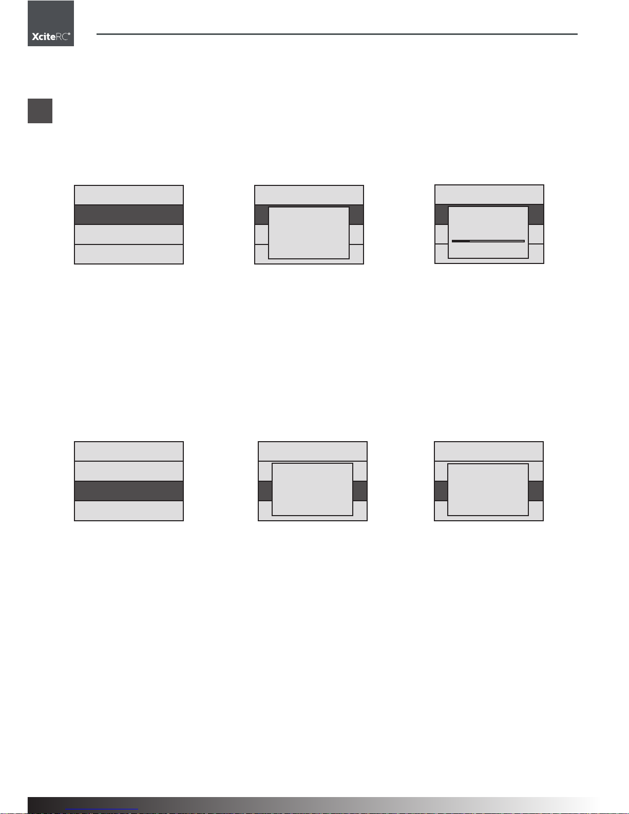
64
50500000 Sender X-6S
SYS.MENU
STICK ADJ.
TRAINER
TIMER SET
SYS.MENU
STICK ADJ.
TRAINER
TIMER SET
ADJUST?
NO
SYS.MENU
STICK ADJ.
TRAINER
TIMER SET
ADJUST
ENTER
345
ENTER
345
SYS.MENU
S TICK ADJ.
TRAINER
TIMER SET
TRAINER
NORMAL
SYS.MENU
STICK ADJ.
TRAINER
TIMER SET
TRAINER
TRAINER
SYS.MENU
S TICK ADJ.
TRAINER
TIMER SET
ENTER
345
ENTER
345
FR
Menu Système
• Appuyez maintenant sur Up ou Down, pour sélectionner le Mode 1 (gaz à droite), Mode 2 (gaz à gauche),
Mode 3 ou le Mode 4. Appuyez sur ENTER pour confirmer votre choix. Appuyez sur Exit pour quitter ce
point du menu.
Remarque: Cette fonction modifie l’attribution des voies proportionnelles des manches de commande. On
attribue ainsi AILE, ELEV, THRO et RUDD. Lorsque le mode Stick est modifié, l’ordre chronologique des
manches AI et El se modifie également. Tenez compte de cela.
Stick Adj
Déterminer le neutre des manches de commande:
• Appuyez sur „Down“ pour sélectionner SYS MENU puis appuyez sur ENTER pour y entrer.
• Avec Up et Down, sélectionnez maintenant STICK ADJ (en surbrillance grise). Avec la touche ENTER,
vous entrez dans le menu.
• Appuyez sur „Down“, pour sélectionner ADJUST YES (en surbrillance grise). Avec la touche Up vous
pouvez revenir sur ADJUST NO.
• Appuyez maintenant sur ENTER pour définir la nouvelle position neutre du manche. L’enregistrement est
affiché par un bref Beep.
• Avant de lancer cette fonction, les manches de commande, ainsi que leurs trims doivent être au neutre.
• Appuyez sur Exit, pour sauvegarder et pour quitter la fonction
Trainer
Sélection Trainer:
• Appuyez sur „Down“ pour sélectionner SYS MENU puis appuyez sur ENTER pour y entrer.
• Avec Up et Down, sélectionnez maintenant TRAINER (en surbrillance grise). Avec la touche ENTER, vous
entrez dans le menu.
• Appuyez sur „Up“ ou „Down“, pour sélectionner la fonction Trainer Normal ou Trainer (en surbrillance
grise). Appuyez maintenant sur ENTER pour exécuter cette fonction.
Normal = Mode de vol normal
Trainer = Software-Simulation d’un vol
A noter:
Sur un ordinateur, cette fonction peut simuler un vol. Pour cela, il faut un cordon spécifique et l’installation
d’un logiciel de simulation.
La prise Trainer, au dos de l’ordinateur ne peut pas être reliée à d’autres appareils électroniques ou autres
émetteurs, cela peut endommager les appareils.
Ce port ne peut pas être utilisé pour l’écolage. Il est réservé au branchement de logiciels de simulation.

65
50500000 Sender X-6S
SYS.MENU
STICK ADJ.
TRAINER
TIMER SET
TIMER SET
00: 00
ENTER
345
FR
Menu Système
Timer Set
• Appuyez sur „Down“ pour sélectionner SYS MENU puis appuyez sur ENTER pour y entrer.
• Avec Up et Down, sélectionnez maintenant TIMER SET (en surbrillance grise). Avec la touche ENTER,
vous entrez dans le menu.
• Avec les touches DEC et INC vous enregistrer la valeur pour le chrono (Timer) en minutes:secondes. Avec
Up et Down vous passez de l’enregistrement des minutes à celui des secondes. Avec la touche ENTER
vous confirmez votre enregistrement. Avec Exit, vous quittez cette fonction.
• En utilisation normale, si vous appuyez sur INC, le chronomètre démarre.
A noter: 20 secondes avant la fin du temps, un bip sonore est émis toutes les secondes. Une impulsion sur
DEC arrête le chronomètre et le remet à 0.

66
50500000 Sender X-6S
4,8 V F100
TIMER
00.00
FUN.
SYS.
.
FUN.MENU
D/R
SUB.TRIM
TRAVEL
FUN.MENU
CH.REV
SWASH.MIX
GYRO.SENE
FUN.MENU
THRO.CURV
MONITOR
PIT.CURV
FUN.MENU
THRO.HOLD
ENTER
345
DR AILE0
RENAME
SAVE AS
RECCVER
H 100
I 0
O 0
L 100
SUB.TRIM
AILE 0
ELEV 0
THRO 0
SUB.TRIM
RUDD 0
GEAR 0
PITH 0
TRAVEL
AILE 100 100
ELEV 100 100
THRO 100 100
TRAVEL
RUDD 100 100
GEAR 100 100
PITH 100 100
DR AILE1
RENAME
SAVE AS
RECCVER
H 100
I 0
O 0
L 100
REV. SW
CH 1 2 3 4 5 6
REV
NOR
FR
Menu des fonctions
Menu des fonctions Hélicoptères
D/R
SUB TRIM
TRAVEL
CH REV

67
50500000 Sender X-6S
SQASH.MIX
AILE -50
PITH -50
ELEV -50
GYRO.SENS
POS0 -100
POS1 100
THRO. CURV
NOR
I 50
O 50
L 100
THRO. CURV
IDLE 0
I 20
O 20
H 75
THRO. CURV
IDLE 1
I 20
O 20
H 3
PIT. CURV
IDLE 0
I 20
O 20
H 0
PIT. CURV
IDLE 1
I 20
O 20
H 75
PIT. CURV
NOR
I 0
O 0
L 0
THRO. HOLD
SW ON
VALUE -20
1
2
3
4
5
6
FR
Menu des fonctions
SWASH MIX
GYRO SENS
THRO CRUV
MONITOR
PIT CURVE
THRO HOLD

68
50500000 Sender X-6S
FUN.MENU
D/R
SUB.TRIM
TRAVEL
DR AILE0
RENAME
SAVE AS
RECCVER
H 100
I 0
O 0
L 100
DR AILE1
RENAME
SAVE AS
RECCVER
H 100
I 0
O 0
L 100
DR AILE0
RENAME
SAVE AS
RECCVER
H 100
I 0
O 0
L 100
A/E/R DR SW
POS0/POS1
A/E/R DR SW
DR ELEV1
RENAME
SAVE AS
RECCVER
H 100
I 0
O 0
L 100
A/E/R DR SW
POS0/POS1
A/E/R DR SW
FR
Menu des fonctions
D/R
D/R (Dual-Rate) pour AILE (Ailerons)
• Appuyez sur „Up“ pour sélectionner FUNC MENU puis appuyez sur ENTER pour y entrer.
• Avec Up et Down, sélectionnez maintenant D/R (en surbrillance grise). Avec la touche ENTER, vous
entrez dans le menu.
• Avec la touche ENTER vous pouvez sélectionner AILE (Ailerons), ELEV (Profondeur) ou RUDD (Direction).
• Avec l’interrupteur A/E/R DR vous choisissez la valeur à modifier, AILE0 ou AILE1
• Avec Up et Down vous choisissez la valeur H ou L qui sera modifiée (respectivement en surbrillance grise).
La courbe affichée se modifie en conséquence.
• Réglez la valeur avec DEC et INC.
• Avec Exit, vous quittez ce point du menu.
Quand l’interrupteur A/E/R DR est en position 0, ce sont les valeurs de AILE0 qui sont modifiées.
Quand l’interrupteur A/E/R DR est en position 1, ce sont les valeurs de AILE1 qui sont modifiées.
D/R (Dual-Rate) pour ELEV (profondeur)
• Appuyez sur „Up“ pour sélectionner FUNC MENU puis appuyez sur ENTER pour y entrer.
• Avec Up et Down, sélectionnez maintenant D/R (en surbrillance grise). Avec la touche ENTER, vous
entrez dans le menu.
• Appuyez une nouvelle fois sur ENTER pour sélectionner ELEV.
• Avec l’interrupteur A/E/R DR vous choisissez la valeur à modifier, ELEV0 ou ELEV1
• Avec Up et Down vous choisissez la valeur H ou L qui sera modifiée (respectivement en surbrillance grise).
La courbe affichée se modifie en conséquence.
• Réglez la valeur avec DEC et INC.
• Avec Exit, vous quittez ce point du menu.
Quand l’interrupteur A/E/R DR est en position 0, ce sont les valeurs de ELEV0 qui sont modifiées.
Quand l’interrupteur A/E/R DR est en position 1, ce sont les valeurs de ELEV1 qui sont modifiées.

69
50500000 Sender X-6S
DR AILE0
RENAME
SAVE AS
RECCVER
H 100
I 0
O 0
L 100
A/E/R DR SW
POS0/POS1
A/E/R DR SW
FUN.MENU
D/R
SUB.TRIM
TRAVEL
SUB.TRIM
AILE 0
ELEV 0
THRO 0
SUB.TRIM
RUDD 0
GEAR 0
PITH 0
TRAVEL
AILE 100 100
ELEV 100 100
THRO 100 100
TRAVEL
RUDD 100 100
GEAR 100 100
PITH 100 100
ENTER
345
IUP/DOWN
345
FUN.MENU
D/R
SUB.TRIM
TRAVEL
ENTER
345
IUP/DOWN
345
STICK
RUDD
FR
Menu des fonctions
D/R (Dual-Rate) pour RUDD (Direction)
• Appuyez sur „Up“ pour sélectionner FUNC MENU puis appuyez sur ENTER pour y entrer.
• Avec Up et Down, sélectionnez maintenant D/R (en surbrillance grise). Avec la touche ENTER, vous
entrez dans le menu.
• Appuyez maintenant encore deux fois sur ENTER pour sélectionner RUDD.
• Avec l’interrupteur A/E/R DR vous choisissez la valeur à modifier, RUDD0 ou RUDD1
• Avec Up et Down vous choisissez la valeur H ou L qui sera modifiée (respectivement en surbrillance
grise). La courbe affichée se modifie en conséquence.
• Réglez la valeur avec DEC et INC.
• Avec Exit, vous quittez ce point du menu.
Quand l’interrupteur A/E/R DR est en position 0, ce sont les valeurs de RUDD0 qui sont modifiées.
Quand l’interrupteur A/E/R DR est en position 1, ce sont les valeurs de RUDD1 qui sont modifiées.
SUB Trim
Réglage du neutre des servos (SUB.TRIM):
• Appuyez sur „Up“ pour sélectionner FUNC MENU puis appuyez sur ENTER pour y entrer.
• Avec Up et Down, sélectionnez maintenant SUB.TRIM (en surbrillance grise). Avec la touche ENTER,
vous entrez dans le menu.
• Avec Up et Down, sélectionnez maintenant AILE, ELEV, THRO, RUDD, GEAR ou PITCH.
• Avec INC et DEC vous modifiez la valeur enregistrée.
• Avec Exit, vous quittez ce point du menu.
Travel
Réglage des butées servos (TRAVEL):
• Appuyez sur „Up“ pour sélectionner FUNC MENU puis appuyez sur ENTER pour y entrer.
• Avec Up et Down, sélectionnez maintenant TRAVEL (en surbrillance
grise). Avec la touche ENTER, vous entrez dans le menu.
• Avec Up et Down, sélectionnez AILE, ELEV, THRO, RUDD, GEAR ou
PITCH. Sélectionnez la valeur de gauche ou celle de droite avec le
manche de commande de la direction.
• Avec INC et DEC vous modifiez la valeur enregistrée.
• Avec Exit, vous quittez ce point du menu.

70
50500000 Sender X-6S
ENTER
345
IUP/DOWN
345
FUN.MENU
CH.REV
SWASH.MIX
GYRO.SENE
REV. SW
CH 1 2 3 4 5 6
REV
NOR
REV. SW
CH 1 2 3 4 5 6
REV
NOR
FUN.MENU
CH.REV
SWASH.MIX
GYRO.SENE
SQASH.MIX
AILE -50
PITH -50
ELEV -50
SQASH.MIX
AILE -30
PITH -50
ELEV 80
ENTER
345
IUP/DOWN
345
FUN.MENU
CH.REV
SWASH.MIX
GYRO.SENE
GYRO.SENS
POS0 -100
POS1 100
GYRO SENS
POS0/POS1
GYRO SENS
ENTER
345
FR
Menu des fonctions
CH.Rev
Réglage du sens de rotation des servos:
• Appuyez sur „Up“ pour sélectionner FUNC MENU puis appuyez sur ENTER pour y entrer.
• Avec Up et Down, sélectionnez maintenant CH.REV (en surbrillance grise). Avec la touche ENTER, vous
entrez dans le menu.
• Avec Up et Down, sélectionnez la voie souhaitée (1 à 6). Modifiez le sens de rotation avec la touche INC
et DEC.
• Avec Exit, vous quittez ce point du menu.
Swash.Mix
Mixage plateau cyclique (uniquement pour hélicoptères CCPM 3 servos à 120°):
• Appuyez sur „Up“ pour sélectionner FUNC MENU puis appuyez sur ENTER pour y entrer.
• Avec Up et Down, sélectionnez maintenant SWASH.MIX (en surbrillance grise). Avec la touche ENTER,
vous entrez dans le menu.
• Avec Up et Down, sélectionnez AILE, PITCH, ELEV. Avec INC et DEC vous pouvez modifier la valeur enregistrée.
• Avec Exit, vous sauvegardez et quittez ce point du menu.
Gyro.Sens
Sensibilité du gyroscope (Gyro sensitivity):
• Appuyez sur „Up“ pour sélectionner FUNC MENU puis appuyez sur ENTER pour y entrer.
• Avec Up et Down, sélectionnez maintenant GYRO.SENS (en surbrillance grise). Avec la touche ENTER,
vous entrez dans le menu.
• Avec l’interrupteur GYRO SENS vous déterminez laquelle des valeurs POS0 ou POS1 sera modifiée.
Lorsque l’interrupteur GYRO SENS-Schalter est en position 0, cette valeur apparaît en surbrillance grise
et vous pouvez la modifier. Si l’interrupteur GYRO SENS-Schalter est en position 1, cette valeur apparaît
en surbrillance grise et vous pouvez la modifier.
• Sélectionnez une valeur en déplaçant le manche de commande de la direction.
• Avec INC et DEC vous modifiez la valeur enregistrée.
• Avec Exit, vous sauvegardez et quittez ce point du menu

71
50500000 Sender X-6S
FUN.MENU
THRO.CURV
MONITOR
PIT.CURV
THRO. CURV
NOR
I 50
O 50
L 100
THRO. CURV
IDLE 0
I 20
O 20
H 75
THRO. CURV
IDLE 1
I 20
O 20
H 3
IDLE SW
NOR/POS0/
POS1
IDLE SW
ENTER
345
FUN.MENU
THRO.CURV
MONITOR
PIT.CURV
ENTER
345
1
2
3
4
5
6
FR
Menu des fonctions
Thro.Curve
Courbe des gaz (Throttle curve):
• Appuyez sur „Up“ pour sélectionner FUNC MENU puis appuyez sur
ENTER pour y entrer.
• Avec Up et Down, sélectionnez
maintenant THRO.CURV (en surbrillance grise). Avec la touche
ENTER, vous entrez dans le menu.
• Avec Up et Down, sélectionnez le point souhaité (L, 1, 2, 3 et H) qui s’affiche dans le champ inférieur.
Vous pouvez respectivement modifier la valeur avec la touche INC et DEC.
• Avec l’interrupteur IDLE vous pouvez choisir une des trois courbes, NOR, IDLE0 et IDLE1.
• Avec Exit, vous sauvegardez et quittez ce point du menu.
Remarque: L’émetteur peut sauvegarder 3 courbes de gaz différentes. Ceci est judicieux, notamment pour
les figures de vol 3D. A ce sujet, renseignez-vous auprès de pilotes expérimentés qui sauront vous conseiller.
Monitor
Système Monitor:
• Appuyez sur „Up“ pour sélectionner FUNC MENU puis appuyez sur ENTER pour y entrer.
• Avec Up et Down, sélectionnez maintenant MONITOR (en surbrillance grise). Avec la touche ENTER,
vous entrez dans le menu.
• Si vous déplacez maintenant les manches de commande ou si vous basculez l’interrupteur d’une voie,
l’affichage de la voie se modifiera en fonction du déplacement des servos. Cette fonction a été intégrée
pour pouvoir visualiser les réglages effectués sur l’émetteur.
• Avec Exit, vous quittez ce point du menu.
Remarque: Cette fonction est une aide lors des réglages de l’émetteur, des trims de chacune des voies et
sert à contrôler les différentes voies

72
50500000 Sender X-6S
FUN.MENU
THRO.CURV
MONITOR
PIT.CURV
PIT. CURV
IDLE 0
I 20
O 20
H 0
PIT. CURV
IDLE 1
I 20
O 20
H 75
PIT. CURV
NOR
I 0
O 0
L 0
IDLE SW
NOR/POS0/
POS1
IDLE SW
ENTER
345
FUN.MENU
THRO.HOLD
THRO. HOLD
SW ON
VALUE -20
TH HOLD
POS0/POS1
TH HOLD
ENTER
345
FR
Menu des fonctions
Pit.Curve
Courbe du Pas (Pitch curve):
• Appuyez sur „Up“ pour sélectionner FUNC MENU puis appuyez sur ENTER pour y entrer.
• Avec Up et Down, sélectionnez
maintenant PIT.CURV (en surbrillance grise). Avec la touche
ENTER, vous entrez dans le
menu.
• Avec Up et Down, sélectionnez le point souhaité (L, 1, 2, 3 et H) qui s’affiche dans le champ inférieur.
Vous pouvez respectivement modifier la valeur avec la touche INC et DEC.
• Avec l’interrupteur IDLE vous pouvez choisir une des trois courbes, NOR, IDLE0 et IDLE1.
• Avec Exit, vous sauvegardez et quittez ce point du menu.
Remarque: L’émetteur peut sauvegarder 3 courbes de Pas différentes. Ceci est judicieux, notamment pour
les figures de vol 3D. A ce sujet, renseignez-vous auprès de pilotes expérimentés qui sauront vous conseiller.
Thro.Hold
Throttle hold:
• Appuyez sur „Up“ pour sélectionner FUNC MENU puis appuyez sur ENTER pour y entrer.
• Avec Up et Down, sélectionnez maintenant THRO.HOLD (en surbrillance grise). Avec la touche ENTER,
vous entrez dans le menu.
• Mettez l’interrupteur TH.HOLD dans la position souhaitée. S’il est en position 0, SW OFF s’affiche à
l’écran, s’il est en position 1, c’est SW ON qui s’affiche.
• Vous pouvez respectivement modifier la valeur (VALUE) avec la touche INC et DEC.
• Avec Exit, vous sauvegardez et quittez ce point du menu.

73
50500000 Sender X-6S
FUN.MENU
CH.REV
MONITOR
V-TAIL
V-TAIL
ELEV1 50
ELEV2 50
RUDD2 50
RUDD1 50
ENTER
345
FR
Menu des fonctions
Menu des fonctions pour modèles classiques
Ce menu comprend les fonctions D/R, SUB.TRIM, TRAVEL, CH.REV et MONITOR. Celles-ci ont déjà été
décrites sous le menu des fonctions des hélicoptères.
Train rentrant Voie 5
Volet d’atterrissage Voie 6
Menu des fonctions pour modèles à empennage en V
Ce menu comprend les fonctions D/R, SUB.TRIM, TRAVEL, CH.REV et MONITOR. Celles-ci ont déjà été
décrites sous le menu des fonctions des hélicoptères.
V-Tail
Mixage Empennage en V
• Appuyez sur „Up“ pour sélectionner FUNC MENU puis appuyez sur ENTER pour y entrer.
• Avec Up et Down, sélectionnez maintenant V-TAIL (en surbrillance grise). Avec la touche ENTER, vous
entrez dans le menu.
• Avec Up et Down, sélectionnez ELEV1, ELEV2, RUDD2 ou RUDD1. Avec INC et DEC vous pouvez modifier la valeur enregistrée.
• Avec Exit, vous sauvegardez et quittez ce point du menu.

74
50500000 Sender X-6S
FUN.MENU
CH.REV
MONITOR
DELTA-MIX
V-TAIL
AILE2 50
AILE1 50
ELEV1 50
ELEV2 50
ENTER
345
AILE
ELEV
PITCH
Avant
FR
Montage / Branchements
Menu des fonctions pour modèles Delta
Ce menu comprend les fonctions D/R, SUB.TRIM, TRAVEL, CH.REV et MONITOR. Celles-ci ont déjà été
décrites sous le menu des fonctions des hélicoptères.
Delta-Mix
Mixages Delta
• Appuyez sur „Up“ pour sélectionner FUNC MENU puis appuyez sur ENTER pour y entrer.
• Avec Up et Down, sélectionnez maintenant DELTA-MIX (en surbrillance grise). Avec la touche ENTER,
vous entrez dans le menu.
• Avec Up et Down, sélectionnez AILE2, AILE1, ELEV1 ou, ELEV2 . Avec INC et DEC vous pouvez modifier
la valeur enregistrée.
• Avec Exit, vous sauvegardez et quittez ce point du menu.
Montage et branchements sur hélicoptères
Mettez l’émetteur en mode Hélicoptère et utilisez ce mode Hélicoptère.
Récepteur

75
50500000 Sender X-6S
FR
Montage / Branchements
Montage et branchements pour modèles à voilure fixe
Mettez l’émetteur sur Avion et utilisez le mode Avion, pas de mixages pour avions classiques.
Attribution des sorties récepteur:
CH1: AILE Aileron
CH2: ELEV Profondeur
CH3: THRO Moteur/Gaz
CH4: RUDD Direction
CH5: GEAR Train rentrant
CH6: FLAP Volets d’atterrissage

76
50500000 Sender X-6S
FR
Montage / Branchements
Montage et branchements pour modèles à empennage en V
Emetteur Voie de réception du mixage
Manche Voie 2 Voie 4
Profondeur +50% -50%
Direction -50% +50%
Mettez l’émetteur sur V-TAIL et utilisez le mode Empennage en V, profondeur et direction seront mixées,
comme sur tout modèle à empennage en V.
Attribution des sorties récepteur:
CH1: AILE Aileron
CH2: ELEV Profondeur
CH3: THRO Moteur/Gaz
CH4: RUDD Direction
CH5: AILE2 Aileron 2
Montage et branchements pour modèles Delta
Emetteur Voie de réception du mixage
Manche Voie 1 Voie 2 Voie 5
Ailerons +50% +50% +50%
Profondeur +50% -50% +50%
Mettez l’émetteur sur DELTA et utilisez le mode Delta, profondeur et direction seront mixées.
Attribution des sorties récepteur:
CH1: AILE Aileron
CH2: ELEV Profondeur
CH3: THRO Moteur/Gaz
CH4: RUDD Direction
CH5: AILE2 Aileron 2

77
50500000 Sender X-6S
FR
Montage / Branchements / Réparations
Charactéristiques techniques
Digital Proportional RC Systéme
Type X-6S
Écran LCD
mWSystème de transmission GFSK
Voies 6
Fréquence 2,4 GHz
Consommation <150 mA
Encombrement 200 x 185 x 105 mm
Réparations, Pièces détachées
Les traces d’une usure normale et les pièces endommagées suite à un accident ne sont pas couverts par la
garantie. La responsabilité du constructeur est
entièrement exclue. L’exclusion de la garantie s’applique en général comme suit :
Pour les modèles de voitures: les pneus usés, les pieces d’entraînement et roues dentées usées, ou des
suspensions tordues ou cassées, le chassis ou la carrosserie
Pour les modèles de bateaux: hélices cassées, superstructures détachées
Pour les modèles d‘avions: tous les dégats causés par un transport non approprié ou un crash.
Si vous découvrez un défaut de fabrication ou une pièce détériorée au moment de l’ouverture de l’emballage
– avant la première mise en route – retournez le modèle sans attendre à votre concessionnaire ou directement chez nous afin que nous procédions à un échange.

78 79
50500000 Sender X-6S
FR
Protection de l‘environnement
Toutes les pièces être disponibles comme pièces détachées. En cas de pièces défectueuses, vous pouvez
vous aider du dessin éclaté pour l’identifier et la commander. En cas de problème ou de questions consultez
votre concessionnaire.
XciteRC Modellbau GmbH & Co. KG - Service, Autenbachstrasse 12, D-73035 Göppingen, Tel. +49 7161
40 799 50
Email: service@xciterc.de
Vous trouverez les pièces détachées chez votre concessionnaire ou online sur http://www.XciteRC.de/
CONSIGNES POUR LA PROTECTION DE L‘ENVIRONNEMENT
Le symbole de la poubelle barrée sur l’emballage signifie que celui-ci ne peut pas jamais être jeté
à la poubelle. Cette mesure contribue à éviter tous les dangers sur l‘environnement et sur les
personnes pouvant résulter d’une élimination sauvage des appareils électriques et électroniques.
Cela favorise les efforts de recyclage.
Le dépôt de tous les appareils électriques ou électroniques dans les points de récupération autorisés près
de chez vous est gratuit. Renseignez-vous auprès de votre commune ou mairie où se trouve le centre de
tri le plus proche de chez vous. Nous reprenons également tous nos appareils électriques ou électroniques
gratuitement après usage si vous nous les renvoyez. Nous les remettrons à un centre de tri ou de recyclage.
Les piles ou les accus doivent être retirés de chaque appareil et doivent être remis au centre de tri approprié
à ce type de déchets.
Informations relatives à la loi de recyclage des piles
Nous commercialisons des piles et des accus et sommes dans ce cas dans l’obligation selon la législation
en vigueur (Battg) d’informer le consommateur comme suit :
Il est formellement interdit de jeter les piles et les accus dans la poubelle domestique, la loi oblige les consommateurs de les remettre à un dépôt homologué après usage. Les piles usagées contiennent des métaux/
produits dangereux qui peuvent entrainer des effets nocifs pour la santé et pour l’environnement en cas
de mauvais stockage ou élimination. Les piles contiennent aussi des matières premières comme du fer, du
cuivre, du zinc, du manganèse ou du nickel qui peuvent être recyclés.
Vous pouvez nous renvoyer les piles et les accumulateurs par poste suffisamment affranchie à l’adresse
ci-dessous :
XciteRC Modellbau GmbH & Co.KG
Autenbachstr. 12
D-73035 Göppingen
Ou vous pouvez les remettre gratuitement au point de collecte le plus proche de chez vous (par exemple,
dans la distribution ou dans les containers de récupération de piles de votre commune). La remise chez
les commercants est limitée aux quantités domestiques et aux marques et type de piles vendues dans ce
commerce.
Sur les piles contenants des produits dangereux figurent le symbole d’une poubelle barrée et le symbole
des métaux dangereux.
Le symbole de la poubelle barrée signifie que les piles et les accumulateurs ne doivent pas être jetés dans
la poubelle classique.
Ci-dessous les symboles que vous reconnaitrez
Cd = Cadmium
Pb = Plomb
Hg = mercure
Li = Lithium
Cd Hg Pb
Li-Po


XciteRC Modellbau GmbH & Co. KG
Autenbachstraße 12
D-73035 Göppingen
Phone: +49 7161 40 799 0
Fax: +49 7161 40 799 99
E-Mail: info@xciterc.de
Web: www.XciteRC.de
 Loading...