

Xceltronix Autocloser Installation Manual And User's Manual

Patent Pending
INSTALLATION MANUAL
AND USER’S GUIDE
Revision 5.8
1

Autocloser is designed and manufactured by
NOTE: This equipment has been tested and found to comply with the limits for a Class
B digital device, pursuant to part 15 of the FCC Rules. These limits are designed to provide reasonable protection against harmful interference in a residential installation. This
equipment generates, uses and can radiate radio frequency energy and, if not installed
and used in accordance with the instructions, may cause harmful interference to radio
communications. However, there is no guarantee that interference will not occur in a
particular installation. If this equipment does cause harmful interference to radio or
television reception, which can be determined by turning the equipment off and on, the
user is encouraged to try to correct the interference by one or more of the following
measures:
- Reorient or relocate the receiving antenna.
- Increase the separation between the equipment and receiver.
- Connect the equipment into an outlet on a circuit different from that to which the
receiver is connected.
- Consult the dealer or an experienced radio/TV technician for help.
CAUTION: Any modifications made to the Autocloser without express approval by
Xceltronix, Inc. could void the user’s authority to operate said equipment.
2

INTRODUCTION
Congratulations on your purchase of an Autocloser automatic garage door closer.
We are certain that this little black box will give you peace of mind knowing that your
garage or shop door will close if you inadvertently leave it open. The Autocloser
works with your existing garage door opener and incorporates the latest microcontroller technology, infrared light sensor, the optional I-Opener system, and
advanced software algorithms to deliver a safe and reliable product.
The Autocloser functions by continuously monitoring the garage door position.
When the device senses that the garage door is open, the device starts a software
timer. When the timer completes it’s count, the Autocloser warns of the impending
garage door closure then shuts the garage door. The operation of the garage door is
achieved by connecting the device to the garage door opener wall button terminals.
This enables the device to simulate the depression of the garage door opener wall
button. The closing sequence can be cancelled by pressing the disable button
(before the audible warning is given), or by pressing the disable button twice if the
audible warning is sounding.
An optional subsystem, the I-Opener system, allows the Autocloser to open and
close a garage door from a remote, secure terminal utilizing an electronic key. Each
electronic key has a unique code that is permanently stored in the key. Each key
provides one of 281,474,976,710,656 possible access combinations. That’s 281
trillion possible numbers. If a thief wanted to circumvent the system by inputting
every possible number, it would take 8,925,513 years because the I-Opener system
reads only one key code per second. The I-Opener system is highly secure, easy to
install and easy to operate.
PRE-INSTALLATION CHECK LIST
1. Verify that your garage door opener complies with the latest govern-
ment safety requirements. The Consumer Products Safety Commission
(http://www.cpsc.gov) has information on the latest garage door opener
requirements mandated by Congress. Garage door openers installed after
1991 are required to have a properly working reversing mechanism. If this
feature does not work on your system, your door could close on an object
such as a child or car and cause severe injury or damage. Garage door
openers installed after 1993 are required to have a photo eye mechanism.
Unlike the reversing mechanism attached to the door, nothing has to
physically touch the door before it reverses. Once the invisible beam from
the photo eye is broken, the door reverses automatically. If your garage
door does not have these government required safety features, replace or
update your garage door opener with a compliant model before installing
the Autocloser. The Autocloser has both an audible beeper and visible
door movement alarm to indicate that the door is about to close. While
3
this is intended to increase the safety of the system, these features are
not intended to nor do they replace the auto reversing safety features that
are required on all garage door openers.
2. Xceltronix, Inc. urges you to re-read your garage door opener instal-
lation and maintenance manual.
safety inspection based on the recommendations of the garage door
opener manufacturer. Test the auto-reversing and photo eye safety features.
3. You need a 110 Volt power outlet available. The outlet should be no
more than four feet from the garage door opener power head.
!!! WARNING !!!
DO NOT USE AN EXTENSION CORD! Extension cords can cause
dangerous overheating conditions and are a fire hazard!
4. Instruct all family members, especially children, about the potential
dangers of a garage door opener.
object in your house. All family members should be instructed to use caution around it. Never stand or play under the door, and never race underneath the door as it closes. Keep all body parts away from the garage
door opener track and drive mechanisms.
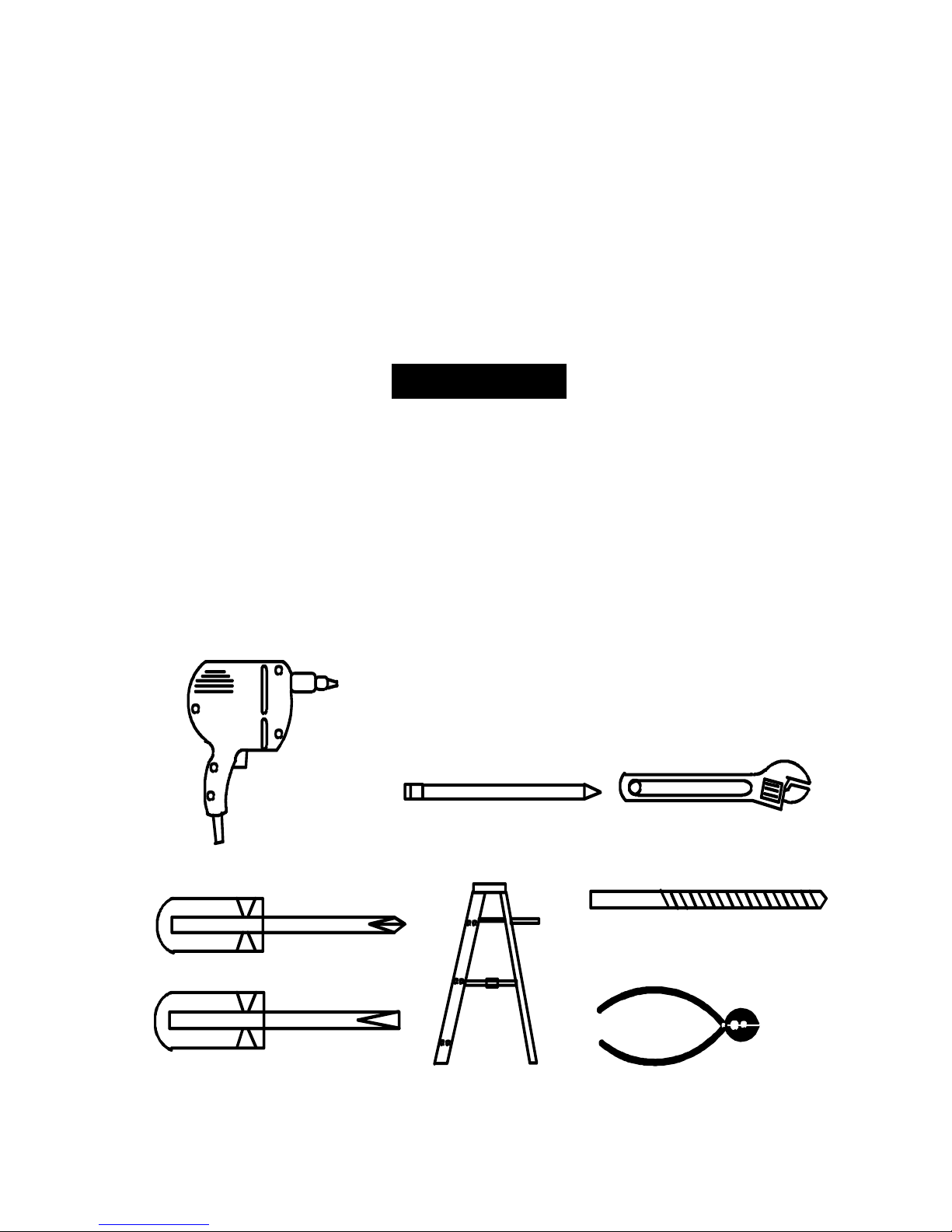
TOOLS RECOMMENDED
Perform routine maintenance and a
!!!!!!WARNING!!!!!!
A garage door is the largest moving
Drill
Phillips screwdriver
Standard screwdri ver
Pencil
Ladder
4
Adjustable wrench
7/16 & 1/8 drill bit
Wire cutter/stripper

PARTS LIST
Description
Item
TOOLS RECOMMENDED
1) 1 terminal wire 2ft.
2) 1 Disable wire 25 ft.
3) 1 Disable button
4) Velcro®
fasteners, 2 each- hook and loop strips
5) 1 Reflector assembly
6) 1 Nut
7) 1 Bolt
8) 1 Lock washer
9) 2 Disable button wood screws
10) 1 Power adaptor
11) 1 I-Opener terminal assembly (optional)
12) 2 I-Opener terminal plate wood screws (optional)
13) 1 I-Opener electronic key (optional)
14) 1 Autocloser control unit
15) Conspicuity tape
Note: Items (1) and (2) may be supplied as a single spool
of wire. Cut the required length of wire for item (1) from the
spool of wire.
5
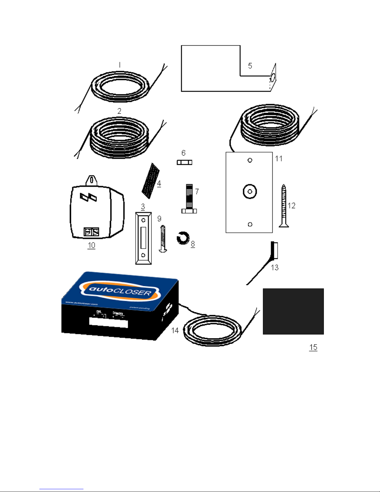
PARTS IDENTIFICATION
6
INSTALLATION OF Autocloser HARDWARE
RNING !!!
To reduce the risk of severe injury or death:
Read all instructions before installing.
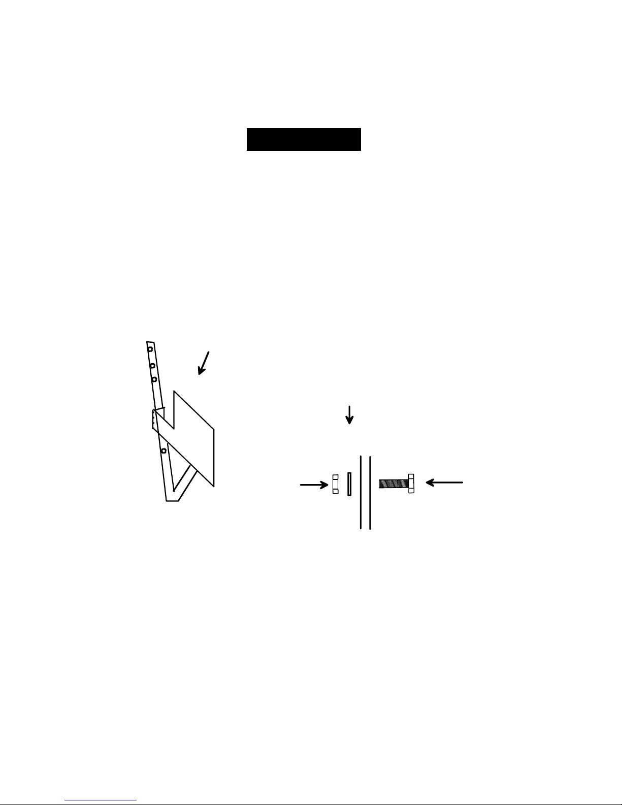
1.
Install reflector assembly.
1a.
OPEN YOUR GARAGE DOOR AND UNPLUG THE GARAGE DOOR
OPENER BEFORE BEGINNING THIS STEP !!! Bolt the reflector assembly, Item
(5), to the garage door opener J brace
TIP: In steps 3 and 4, the Autocloser control unit will be installed under the garage
door opener power head assembly. The infrared sensor will be lined up with the reflector (Fig. 1-2) Install the reflector low enough on the J brace so that the infrared
sensor on the Autocloser can be lined up with the reflector
Attach reflector using an existing
hole in the J brace.
Fig. 1-1
!!!!!!WARNING!!!!!!
!!! WARNING !!!
(Fig. 1-1).
Nut, lock washer,
J brace, reflector, bolt
.
7
Garage door opener
power head assembly
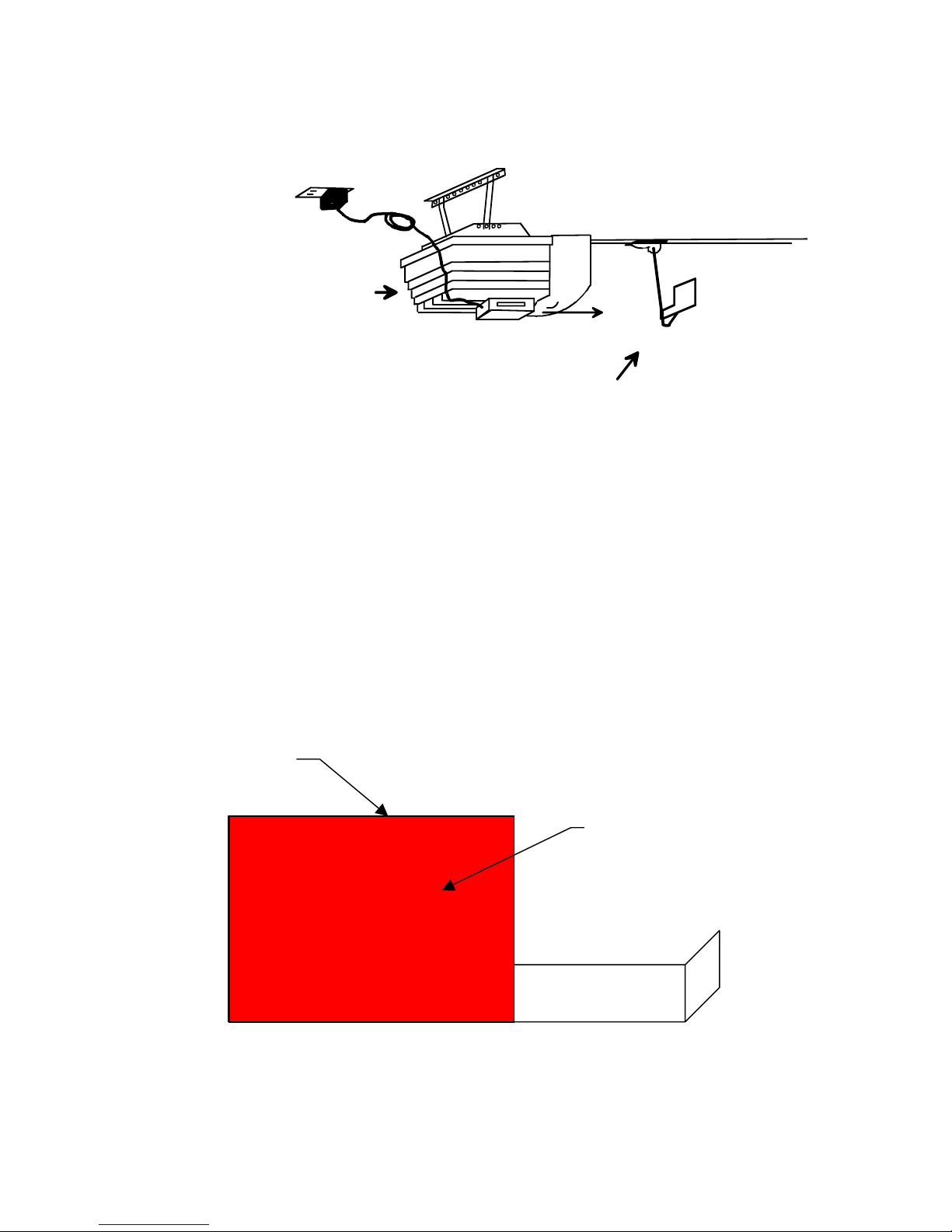
1b. Attach reflective conspicuity tape to reflector plate. Peel off adhesive backing from the
conspicuity tape and affix to side of reflector plate facing the Autocloser unit. Tape should be
aligned to cover most of the rectangular portion of reflector plate
NOTE: Conspicuity tape is a special form of reflective tape which will improve the reflective
characteristics of the plate. The application of this tape will simplify the installation and enhance the performance of the unit.
Fig. 1-3
Reflector
The reflector should be
as low as the bottom of
the garage door opener
power head assembly
Fig. 1-2
(Fig. 1-3)
Conspicuity Tape
.
8
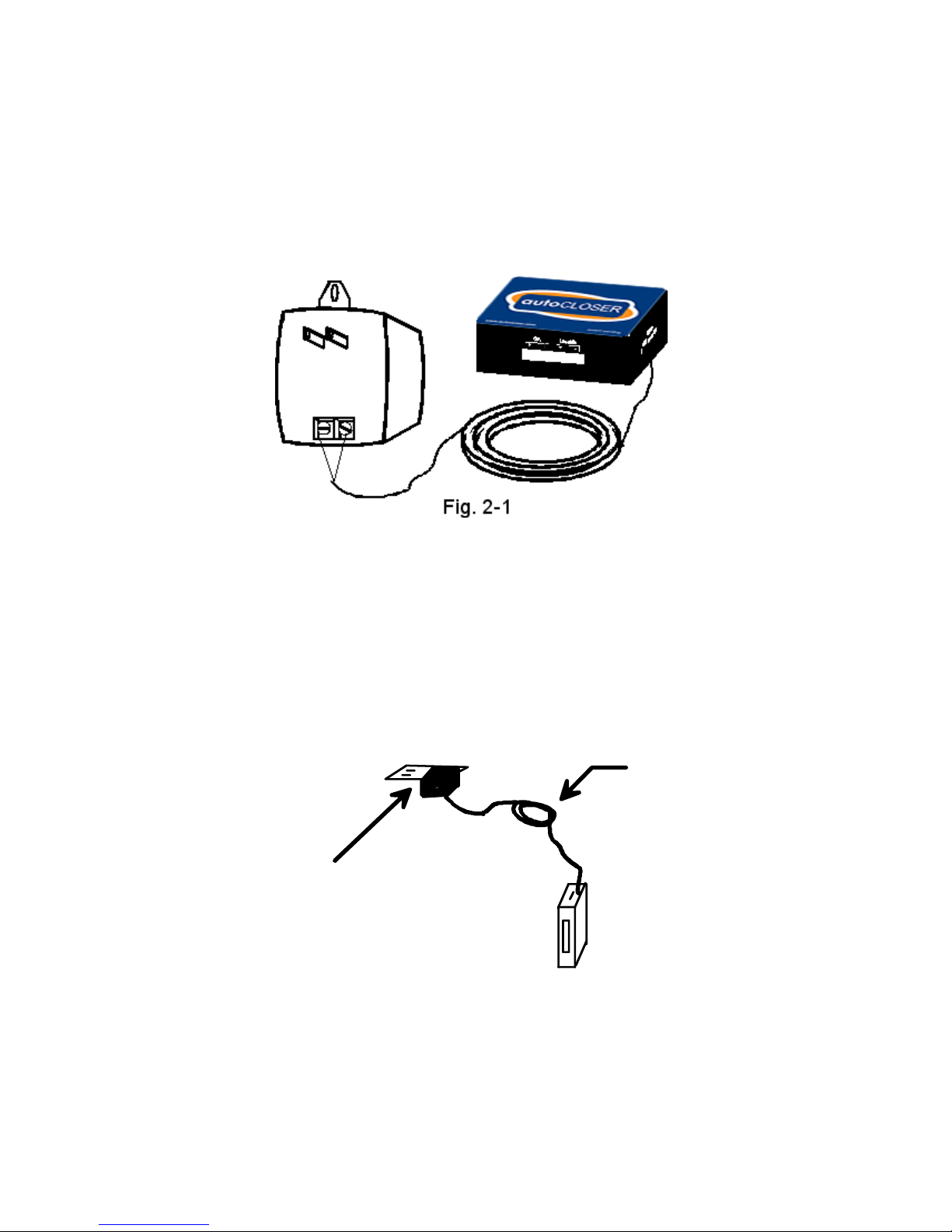
2. Connect power to the Autocloser
adapter. Attach each power wire to one of the screw terminals on the power adapter
(Fig. 2-1).
Unscrew the center screw on the plate of the household receptacle that you will be using
to power the Autocloser. With the plate held in position, plug the Autocloser power
adapter into the receptacle. Use the receptacle plate screw to screw down the adapter tab
(Fig. 2-2) .
Either wire may be attached to either terminal.
. The Autocloser uses a 110 Volt AC / DC power
Screw down
the adaptor
tab with the
receptable
plate center
screw.
Bundle
wires with
twist tie.
Fig. 2-2
9
!!! WARNING !!!
THE POWER ADAPTER MUST BE SCREWED DOWN TO PREVENT THE
ADAPTER FROM BEING ACCIDENTALLY UNPLUGGED. THIS ADAPTER IS
HEAVY AND CAN CAUSE BODILY INJURY IF IT HITS SOMEONE!!!
cess wire in a roll and apply a twist tie, to prevent it from hanging down and becoming an
obstruction.
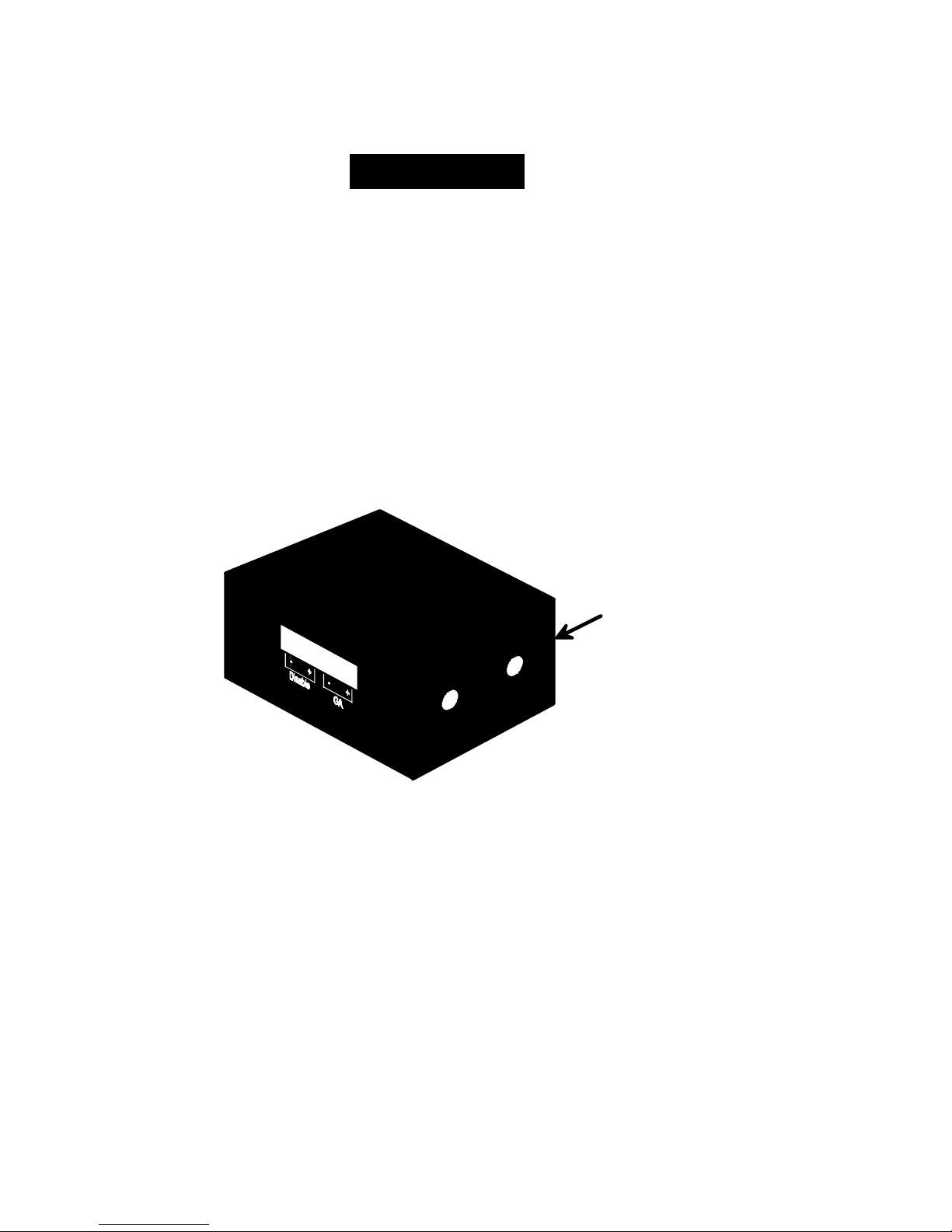
Determine the Autocloser mounting location
3.
emitter/detector to determine the position of the garage door. Note the position
3-1)
of the infrared sensors. To ensure correct operation, the Autocloser unit must
be no more than 36 inches from the reflector plate when the door is fully open.
!!!!!!WARNING!!!!!!
Bundle ex-
. The Autocloser uses an infrared
(Fig.
Vent
Hole
Fig. 3-1
Infrared
Sensors
10
 Loading...