

XAVi X8122r User Manual

X8122r User’s Manual Version 1.0
1 / 70

X8122r User’s Manual Version 1.0
2 / 70
TTaabbllee ooff CCoonntteennttss
CChhaapptteerr 11 –– GGeettttiinngg SSttaarrtteedd
I. Overview……………………………………………………………………………………. 5
II. Features………………………………………………………………………………….….6
III. Packaging……………………………………………………………………………….….. 7
IV. Appearance…………………………………………………………………………….…... 8
Front Panel……………………………….…………………………………………….…... 8
Rear Panel………………………………………………….…………..…………….……. 9
V. Hardware Installation…………………….………………………………………….…… 10
VI. Management………………………………………………………………………….…... 11
VII. Default Values……………………………………………………………………….……. 12
VIII. Software Upgrade………………………………………………………………………... 13
IX. Console Setup……………………………………………………………………….…… 14
CChhaapptteerr 22 –– WWeebb IInntteerrffaaccee MMaannaaggeemmeenntt
I. Overview……………………………..…………………………………………...………. 15
II. Preparation…………………………………………..……………….…..…….………… 15
III. Login……..……………………………………………..…………...…...….………….… 16
A. Home………..…………………………………….…………..…….…………….… 17
B. LAN………………………………………….………………………………………. 18
C. WAN…………………………………………………………………………………. 21
D. Bridging……………………………………………………………………………… 29
E. Routing………………………………………………………………………………. 30
F. Services………………………………………………………………………………32
G. Admin………………………………………………………………………………... 41
CChhaapptteerr 33 –– QQuuiicckk PPrroottooccooll SSeettuupp
Overview………………………………………………………………………………….…….. 47
A. RFC 1483 Bridge………..………………………………………………….……… 48
B. PPPoE Route Configuration………………………………………….…………... 51
C. RFC 1483 + NAT.………………………………………………………….………. 52
D. PPPoA Route Configuration…………………………..………………….…….… 55
E. IPoA Route Configuration……….….…………………..………………….……... 58
F. DHCP Configuration…….………..……………………..…………………….…... 60
G. NAT Configuration..………………………………………..…………..………….. 62

X8122r User’s Manual Version 1.0
3 / 70
TTaabbllee ooff CCoonntteennttss
AAppppeennddiixx AA –– SSppeecciiffiiccaattiioonnss
A1. Hardware Specifications..…………………………………………………………….... 64
A2. Software Specifications……….………………………………………………………... 65
AAppppeennddiixx BB –– WWaarrrraannttiieess
B1. Product Warranty………………………………………………….…………………….. 66
B2. Warranty Repair……………………………………………………………………….… 67
B3. Out-of-Warranty Repair. ………………………….………………………………….… 67
AAppppeennddiixx CC –– RReegguullaattiioonnss
C1. FCC Part 15 Notice…………………………………………………….………..……… 68
C2. IC CS-03 Notice……….……………………………………………………………….…69
CCoonnttaacctt IInnffoorrmmaattiioon
n
……………………………………………………………………. 70

X8122r User’s Manual Version 1.0
4 / 70
RReevviissiioonn MMaarrkkss
Revision Date Notes
V 1.0
July 16, 2003
Software: 3.904CHTO.8122A

X8122r User’s Manual Version 1.0
5 / 70
Chapter 1
Getting Started
I. Overview
X8122r is multi-mode ADSL Router, compliant with ANSIT1.413
Issue 2, ITU G.992.1 (G.dmt) Annex A/B, G.992.2 (G.lite). X8122r
provides high-speed Internet access via one WAN port over ATM over
ADSL, and also connects to a corporate network via four-10/100BaseT
Ethernet ports. Interchangeable between both routing and bridging,
X8122r offers convenient configuration and management. X8122r
allows service providers to deploy ADSL rapidly over existing wire
infrastructure (POTS or ISDN line).

X8122r User’s Manual Version 1.0
6 / 70
II. Features
High Speed Asymmetrical Data Transmission on a Single
Twisted Copper Pair.
Full rate operations up to 8Mbps downstream and up to 1Mbps
upstream. G.lite operation up to 1.5Mbps downstream and
512Kbps upstream.
Four-10/100BaseT Ethernet Switch Hub for a PC or LAN
connection.
DHCP server support for easy LAN IP address management.
Supports PPPoE (RFC2516), PPP (RFC2364), and IP (RFC
2225/RFC1577) over ATM over ADSL.
Supports RFC2684 (RFC1483) Bridged/Routed for both
LLC/VC MUX.
Allows LAN users to access the Internet through Network
Address Translation (NAT, IP sharing) simultaneously.
Local OAM&P through command line interface via RJ-45
Ethernet port or RS-232 Craft port (optional).
Configuration and management via local Telnet through the
four Ethernet port interfaces, and remote Telnet through the
ADSL interface.
Supports applications such as TFTP, DHCP, Telnet, HTTP,
and FTP.
Firmware upgradeable through FTP.
Interoperability complies with TR-48, U-R2.

X8122r User’s Manual Version 1.0
7 / 70
III. Packaging
This package consists of the following items:
X8122r ADSL device unit
RJ-45 Cable
RJ-11 Cable
AC Adapter
User’s Manual Floppy Disk
X8122r User’s Manual Version 1.0
8 / 70
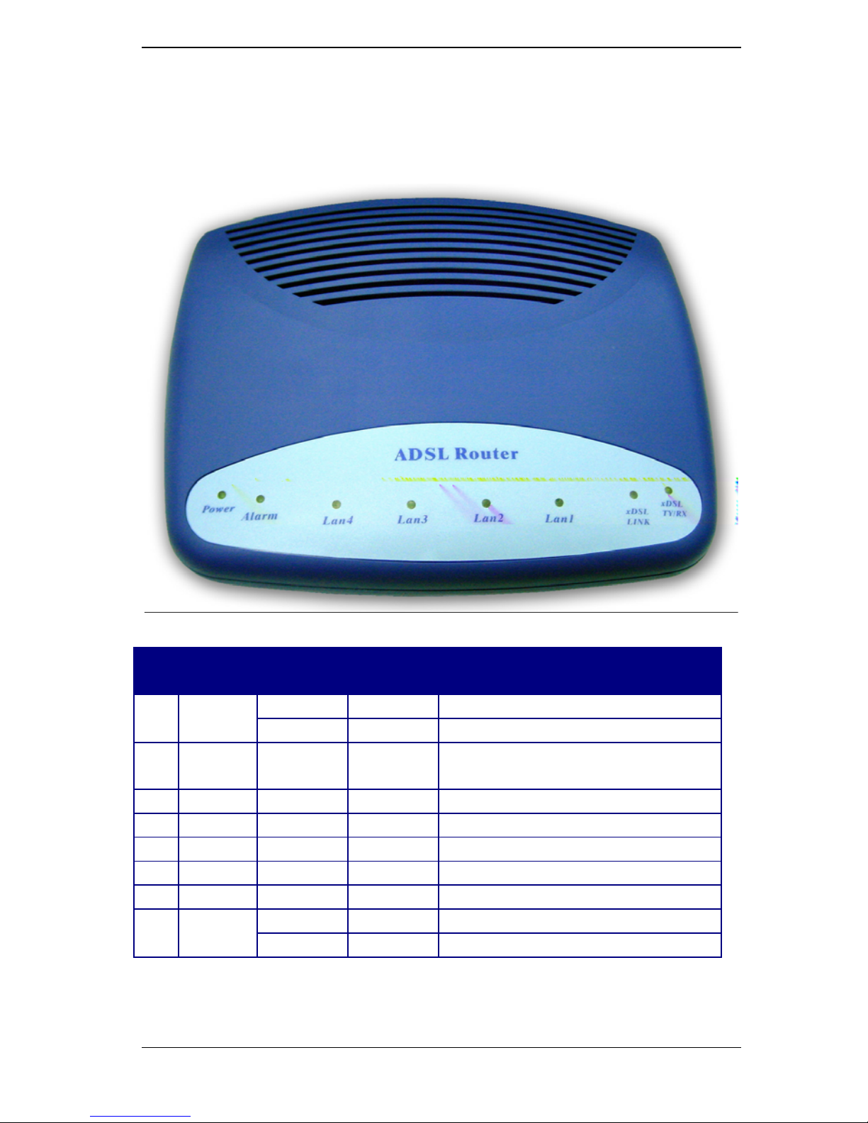
IV. Appearance
Front Panel
Label LED
Status
Color Description
Blinking Green Training with DSLAM.
1
xDSL
TY/RX
ON Green ADSL link is ready.
2
xDSL
LINK
ON Green Ethernet transmitting/receiving.
3 LAN 1 ON Green Ethernet port 1X connected.
4 LAN 2 ON Green Ethernet port 2X connected.
5 LAN 3 ON Green Ethernet port 3X connected.
6 LAN 4 ON Green Ethernet port 4X connected.
7 PWR ON Green Power supply is connected.
Blinking Red Booting up.
8 ALM
ON Red Error.
1 2 3 4 5 6 8 7

X8122r User’s Manual Version 1.0
9 / 70
Rear Panel
Label Description
1 ON/OFF Power switch.
2 PWR Power jack; connect to a power adapter.
3 CONSOLE
Serial port; connect to an ASCII data
terminal.
4 1X~4X RJ-45 port; connect to a PC or LAN.
5 RES
Reset the modem back to factory settings by
holding down on this button.
6 WAN
RJ-11 port; connect to the ADSL outlet.
2 3 4 1 5 6
X8122r User’s Manual Version 1.0
10 / 70
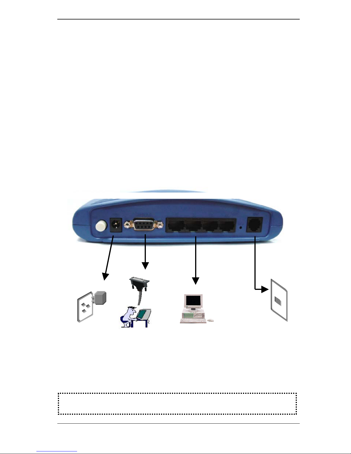
V. Hardware Installation
1. Connect one end of the ADSL cable to the WAN port of
X8122r
and the other end to the ADSL wall outlet.
2. Use a RJ-45 cable to connect one end to the Ethernet port of
X8122r, and the other end to the LAN or a PC with an Ethernet
adapter installed.
3. Use a 9-pin RS-232 cable to connect the Console port to a
serial port of a terminal such as PC with data terminal
emulation software (Hyper Terminal) installed, in order for local
management.
4. Plug in the AC adapter to the AC power socket, and the other
end into the PWR inlet of X8122r.
ADSL Outlet
1
Power Supply
Management Terminal
PC
2
3 4
Note:
Be sure to use a RJ-45 crossover cable while connecting to a hub.

X8122r User’s Manual Version 1.0
11 / 70
VI. Management
X8122r supports simple, flexible, and easy-to-operate methods for
management purposes. X8122r can be managed via the following
paths:
Console port – use the RS-232 cable for connecting
X8122r to a console terminal or a PC running a terminal
emulation program, such as Hyper Terminal. (For further
details, See Chapter 1: IX Console Setup)
Local Ethernet Port (Telnet) – connect the Ethernet port to
your local area network or to directly to a PC. “Telne t”
X8122r from any workstation in the LAN. The default local
Ethernet IP address is “192.168.1.1”.
Local Ethernet Port (Web Browser) – connect the Ethernet
port to your local area network or directly to a PC. Launch
your web browser and enter default local Ethernet IP
address “192.168.1.1” into the address bar.
ADSL Port from Remote Site – while the ADSL connection
is in service, you may remotely “Telnet” X8122r from a
workstation connected to the CO equipment.
Note: As operating an ADSL device requires technical know-how and
experience. It is recommended that only qualified technical staffs
manage X8122r. Therefore, a password authentication is required when
you enter the web interface. To obtain the password, see the Default
Values section.

X8122r User’s Manual Version 1.0
12 / 70
VII. Default Values
X8122r is pre-configured with the following parameters; you may
also re-load the default parameters by rebooting the router into the
Default configuration from the web browser.
Default Mode: Bridge Login Name: admin
Password: admin
Bridge Mode Setting WAN and ADSL
Ethernet (local) IP: 192.168.1.1 Local Line Code: Auto
Subnet Mask: 255.255.255.0 Trellis Mode: Enable
Full Duplex: Auto FDM Mode: Fdm
Protocol: RFC1483, Bridge Mode Coding Gain: Auto
VPI/VCI: 8/35 Transmit Power Atten: 0dB
Class (QoS): UBR
Spanning Tree: Disable
Packet Filter: Any
Router Mode Setting DHCP Server: Disable
Ethernet (local) IP: 192.168.1.1 DNS Relay: Disable
Subnet Mask: 255.255.255.0
Note: The User Name and Password are case-sensitive.

X8122r User’s Manual Version 1.0
13 / 70
VIII. Software Upgrade
You may easily upgrade X8122r embedded software by obtaining
the compressed upgrade kit from the service provider then following
the steps:
1. Extract the ZIP file for updated firmware.
2. Connect X8122r via one of the four local ports or remote ADSL
link. Make sure that X8122r 4 port IP address and your terminal
are properly configured, then you can successfully “ping”
X8122r. The default local IP address is 192.168.1.1.
3. Under DOS prompt, execute FTP command “open <IP
address of X8122r>”, then input user name and password.
4. Execute upload command “put tepatch.bin“.
5. This upgrading process might last as long as 60 seconds.
6. Then reboot X8122r with new software.
Note 1: X8122r software may also be upgraded through the web interface.
See Chapter 2: G. Admin, 3. Image Upgrade
Note 2: Strictly maintain stable power to X8122r while upgrading its
software. If the power fails during the upgrading process, contents in the
memory could be destroyed, and the system may hang. In such a case,
you must call the dealer or system integrator for repairs.

X8122r User’s Manual Version 1.0
14 / 70
IX. Console Setup
Connect the RS-232 console port to an ASCII data terminal or a
PC with Widows serial Terminal mode of VT-100 (Hyper Terminal). To
Start the Hyper-terminal, follow the steps below.
1. Start "Hyper-terminal" program
On Windows 98/NT
Click on the Start button Programs Accessories
Hyper Terminal Group Double Click Hypertrm.exe
Enter Connection Name Select Icon Click OK.
2. Select COM port to communicate with the modem
Choose direct to COM1 or COM2 click OK.
3. Set Port Properties
Port Setting:
− Bit per second: 38400
− Data bits: 8
− Stop bits: 2
− Parity bits: None
− Flow Control: None
Settings:
− Function, arrow, and ctrl keys act as: Windows keys
− Emulation: Auto-detect
− Back-scroll buffer lines: 500
ASCII Setup:
− Echo typed characters locally
− Line delay: 0 milliseconds
− Character line feeds incoming line ends: enable

X8122r User’s Manual Version 1.0
15 / 70
Chapter 2
Web Interface Management
I. Overview
The Web management is provided in order to manage the ADSL
device as easily as possible. It provides a very user-friendly
configuration and graphical interface through a Web based platform.
You can configure a bridge or a router, as you feel appropriate. In the
section below, each configuration item is described in detail.
II. Preparation
1) Please refer the hardware installation procedure to install
modem.
2) You should configure the PC to the same IP subnet as the
modem.
For example: The modem: 192.168.1.1
Your PC: 192.168.1.x
3) Let your PC access the modem, and make sure that the
PING function is working properly. The default IP address of
this modem could be found in the default settings section.
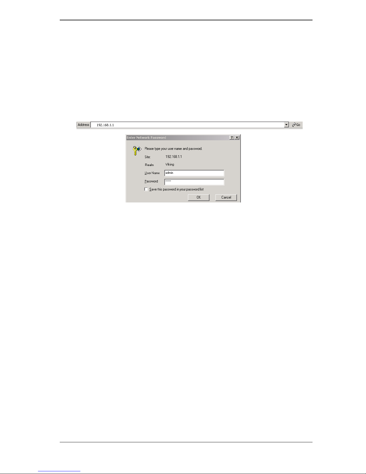
4) Open the Web browser (Internet explorer or Netscape), enter
the default IP address “192.168.1.1” for the website address
to access the web management page.
5) The Login dialog box will pop up first.
X8122r User’s Manual Version 1.0
16 / 70
III. Login
The window Enter Network Password will pop up while starting
the configuration. With the window open, type admin for both the
Username and the Password. You can also edit the Username
and Password or add new users. (For further details, see G.
Admin: 1. User Config)
After you log into the web interface, you will notice that it is divided
into seven different sections, or tabs. From this point on, each tab
is described in detail along with instructions for configuration. The
seven tabs are:
A. Home
B. LAN
C. WAN
D. Bridging
E. Routing
F. Services
G. Admin
X8122r User’s Manual Version 1.0
17 / 70
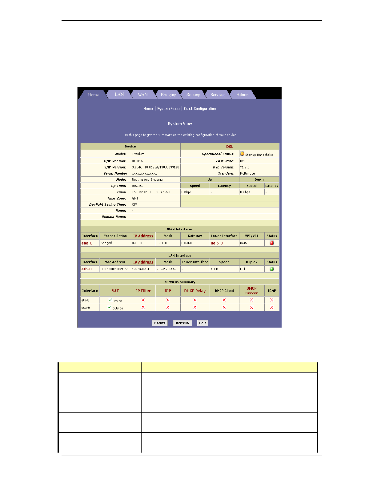
A. HOME
After logging in, the first tab that will be displayed is the Home tab.
Under this tab, the System View page is displayed. This page
displays a summary of the interfaces and their settings.
This page is divided into five sections. The table below describes
each section.
Section Name Description
Device Displays model name, hardware/software
version, device mode, uptime, current time,
time zone, daylight savings time, and domain
name.
DSL Displays operation status, last state, DSL
version, and DSL standard.
WAN Interface Displays the WAN interface name,
enca
p
sulation type, IP address, subnet mask,
X8122r User’s Manual Version 1.0
18 / 70
lower interface, VPI/VCI values, and
operational status.
LAN Interface Displays the LAN interface name, MAC
address, IP address, subnet mask, lower
interface, transmission speed, duplex type
and operational status.
Services Summary Displays the interface name, and
enabled/disabled features, such as: NAT, IP
filter, RIP, DHCP relay, DHCP client, DHCP
server, and IGMP.
To add, change, or remove any of the interface settings, click on
the interface name.
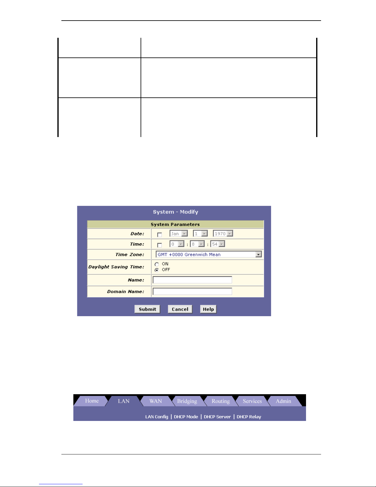
Click on the Modify button to set the device date, time, time zone,
and other related settings. Click on the Submit button when
completed.
B. LAN
Click on the LAN tab to view its sub-menu’s and configure the
LAN settings. The four sub-menu’s are: LAN Config, DHCP Mode,
DHCP Server, and DHCP Relay. Each sub-menu is described below.
X8122r User’s Manual Version 1.0
19 / 70
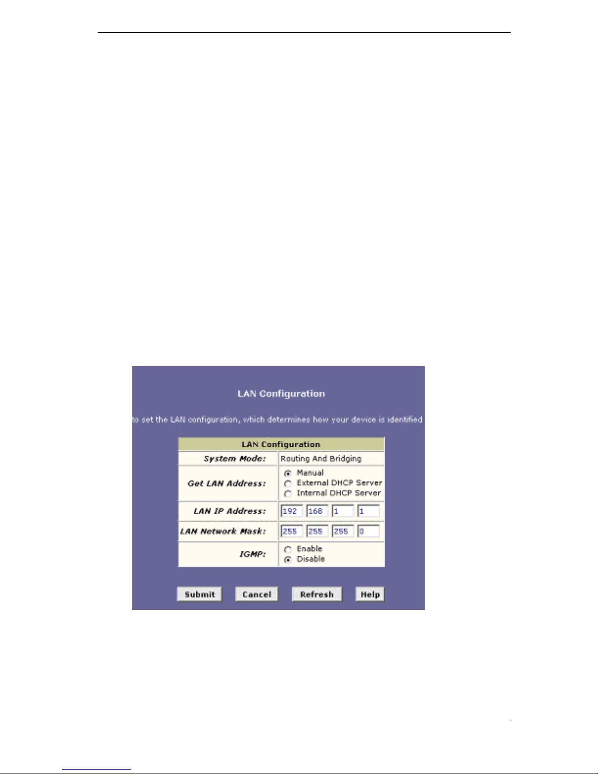
1. LAN Config
Click on the LAN Config link to change the LAN IP address/
subnet mask, decide where the LAN is getting its IP address from, and
enable or disable IGMP. Follow the steps below in order to set up the
LAN.
I. Get LAN Address: Select Manual if you would like to enter
your own IP address. Select External DHCP Server if a DHCP
server other than this device assigns the IP addresses. Select
Internal DHCP Server if you would like this device to assign
the IP addresses.
II. LAN IP Address: Enter the LAN IP address into these text
boxes.
III. LAN Network Mask: Enter the subnet mask of the LAN IP
address into these text boxes.
IV.
IGMP: Depending on your ISP’s settings, choose to enable or
disable IGMP.
V. Click on the Submit button when completed.
X8122r User’s Manual Version 1.0
20 / 70
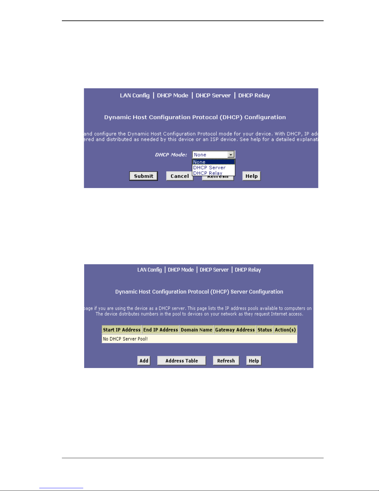
2. DHCP Mode
Click on the DHCP Mode link to select a DHCP setting. From the
drop down list, select DHCP Server, DHCP Relay, or None. Click on
the Submit button when completed.
3. DHCP Server
Click on the DHCP Server link to view the DHCP Server settings.
The table displays the DHCP server settings, this includes: start IP,
end IP, domain name, gateway address, and status. Click on the Add
button to enable a DHCP server and fill in the IP information based on
your ISP settings.
X8122r User’s Manual Version 1.0
21 / 70
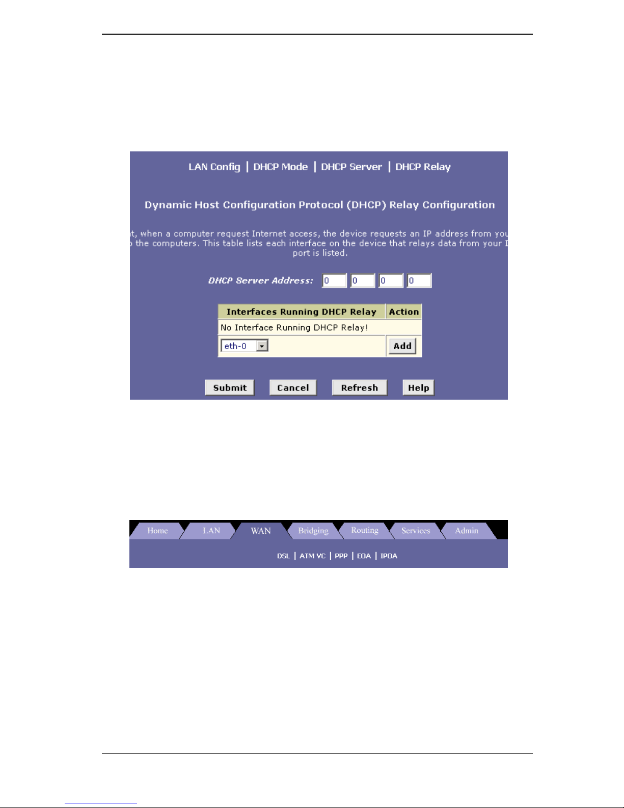
4. DHCP Relay
Click on the DHCP Relay link to view the DHCP Relay settings. Fill
in the DHCP server IP address in the text boxes and select an
interface name from the dorp down list, then click on the Add button to
complete the DHCP Relay configuration.
C. WAN
Click on the WAN tab to view its sub-menu’s and configure the
WAN settings. The five sub-menu’s are: DSL, ATM VC, PPP, EOA,
and IPOA. Each sub-menu is described below.
1. DSL
Click on the DSL link to view the DSL status. Click on the DSL
Param button to view the DSL parameters and the Stats button to
view the DSL statistics. Both the DSL Parameters and DSL
Statistics are described below.
Click on the Clear button to clear and refresh the DSL status. You
may also change the page refresh rate by selecting a different
time period from the Refresh Rate drop down list.
 Loading...