

NMS 410/450X
Quantitative NMT Monitor
Precision Nerve Locator
Product Code: XT-45006-EN
XM400-21A04 v10

Manufacturer
Xavant Technology PTY (LTD)
Unit 102, The Tannery Industrial Park, 309 Derdepoort Rd
Silverton, Pretoria, South Africa, 0184
Tel: +27 (0) 12 743 5959
Fax: +27 (0) 86 547 0026
E-mail: support@xavant.com
Web: www.xavant.com
Legal Representative in the EU
Emergo Europe
Prinsessegracht 20, 2514 AP The Hague
The Netherlands
Caution
Federal (US) law restricts this device to sale by or on the order of a physician.
Indications for use:
This product is a nerve stimulation device designed to be used by an anaesthetist during
• General Anaesthesia, for the purpose of establishing the efficacy of a Neuromuscular
Blocking Agent using non-invasive surface electrodes (not supplied) (NMS450X).
• Regional Anaesthesia for the purpose of
• Nerve mapping using the non-invasive Nerve Mapping Probe (supplied).
• Nerve locating using invasive electrodes/needles (not supplied).
Contraindications:
• Infection of the puncture site.
• Known neurological disorders.
• Severe coagulation disorders.
Warnings:
• Read the entire User Manual before attempting to use the device.
• Use of cables or accessories other than those supplied with the STIMPOD may result
in serious injury.
• Maintenance on this device may only be performed by the manufacturer or persons
explicitly authorized by the manufacturer.
• Do not use the STIMPOD in close proximity to equipment that produces strong
electromagnetic fields, such as high frequency surgical equipment. The cable leads
could act as antennae and dangerous currents could be induced as a result.
• Do not apply the STIMPOD to patients with implanted electrical devices, such as
cardiac pacemakers, without first consulting with an appropriate medical specialist.
• The device should not be used adjacent to or stacked with other equipment and that
if adjacent or stacked use is necessary, the device should be observed to verify normal
operation in the configuration in which it will be used.
• The patient should avoid contact with metallic objects that are grounded, produce
an electrical conductive connection with other equipment and/or enable capacitive
coupling.
• The cables should be positioned in such a way that they do not contact either the
patient or other cables.
• Simultaneous connection of a patient to high frequency surgical ME equipment and
the STIMPOD may result in burns and possible damage to the stimulator.
• Operation in close proximity (e.g. 1m) to a shortwave or microwave therapy ME
equipment may produce instability in the stimulator output.
• Application of electrodes near the thorax may increase the risk of cardiac fibrillation.
• No modification of this equipment is allowed.
• Do not modify this equipment without authorization of the manufacturer.
• If this equipment is modified, appropriate inspection and testing must be conducted
to ensure continued safe use of the equipment.
Cautions:
• Prior to changing the batteries be sure to switch off the device and remove all the
cables.
• Remove elements which may adversely affect the connection between the
electrodes and the skin, e.g., dirt, hair, oil.
• Ensure that ECG electrodes are not damaged or dried out.
• Large current densities associated with failing ECG electrodes may cause superficial
burns.
2

• The Stimpod is designed to be compatible with a standard ECG electrode, however,
for high currents the use of a dedicated NMT electrode such as the Xavant XT45008
is recommended.
• Electrodes that have current densities exceeding 2mA/cm2 may require special
attention of the operator.
• This product must be stored at 0 – 50°C.
• This product must be transported in the carry case provided.
• This product and all the accessories have been certified latex free.
• Inspect all parts for any damage or manipulation. Never use any damaged or
manipulated part!
• If an electrically conductive surface of the Stimpod device or its cables are exposed,
such electrically conductive surface may shock a person handling it. Do not use such
a device or accessory, please contact the manufacturer for repair.
• The refractory period delay is set at a default value to prevent the user from
repeating stimulation while the nerve synapse is recovering from effects of the
previous stimulation. A refractory period of less than 12 seconds in TOF mode is not
advisable as measurements might not represent the effect of blocking agents on the
neuromuscular junction.
Application Specication:
• The patient population includes patients of all ages, weight and nationality. Patient
health and state is described in contraindications, warnings and cautions.
• The user must be a medical professional with knowledge of anatomy.
• The use environment requirements of the device such as the medical practice and
operating room is described in the guidance and manufacturers declaration.
• The device can be used on any part of the body except for limitation described in
warnings and cautions or identified in section 3 for the NMT mode.
Warranty:
• The Stimpod (device only) carries a 24 Month Warranty against defects, provided that
the device was used in accordance with the operating instructions.
• The cables included in the Stimpod Kit carry a 6 Month Warranty against defects,
provided that they were used in accordance with the operating instructions.
• The Stimpod enclosure should not be opened under any circumstances. Opening
the unit will void the warranty.
STIMPOD (NMS 410/450X) conforms to the following
standards:
• IEC 60601-1, IEC 60601-2-10
• IEC 60601-1-2: CISPR 11 Group1 class A; IEC 61000-4-2; IEC 61000-4-3
• ISO 13485, Directive 93-42-EEC
3
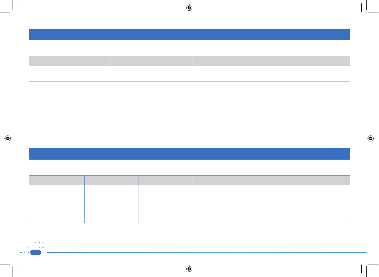
Guidance and manufacturers declaration – electromagnetic emissions– for all equipment and systems
The STIMPOD NMS 410/450X is intended for use in electromagnetic environment specified below. The customer or user of the STIMPOD NMS 410/450X should assure that it is used
in such an environment
Emission Test Compliance Electromagnetic Environment – Guidance
RF Emissions
CISPR 11
Group 2 – Class A The STIMPOD NMS 410/450X must emit electromagnetic energy in order to perform its
intended function. Nearby electronic equipment may be affected.
The STIMPOD NMS 410/450X is suitable for use in all establishments, other than
domestic establishments and may be used in domestic establishments and those
directly connected to the public low voltage power supply network that supplies
buildings used for domestic purposes, provided the following warning is heeded:
WARNING: This equipment/system is intended to be used by healthcare professional
only. This equipment/system may cause radio interference or disrupt the operation
of nearby equipment. It may be necessary to take mitigation measures, such as reorienting or re-locating the STIMPOD NMS 410/450X or shielding the location
Guidance and manufacturers declaration – electromagnetic immunity- for all equipment and systems
The STIMPOD NMS 410/450X is intended for use in the electromagnetic environment specified below. The customer or the user of the STIMPOD NMS 410/450X should assure that it
is used in such an environment
Immunity Test IEC 60601 test level Compliance level Electromagnetic environment - guidance
Electrostatic discharge (ESD)
IEC 61000-4-2
Power frequency (50/60 Hz)
magnetic field
IEC 61000-4-8
± 6 kV contact
± 15 kV air
30 A/m 50 Hz
± 6 kV contact
± 15 kV Air
30 A/m (Effective)
Floors should be wood, concrete or ceramic tile. If the floors are covered with synthetic
material, the relative humidity should be at least 30%
Power frequency magnetic fields should be at levels characteristic of a typical location
in a typical commercial or hospital environment.
4
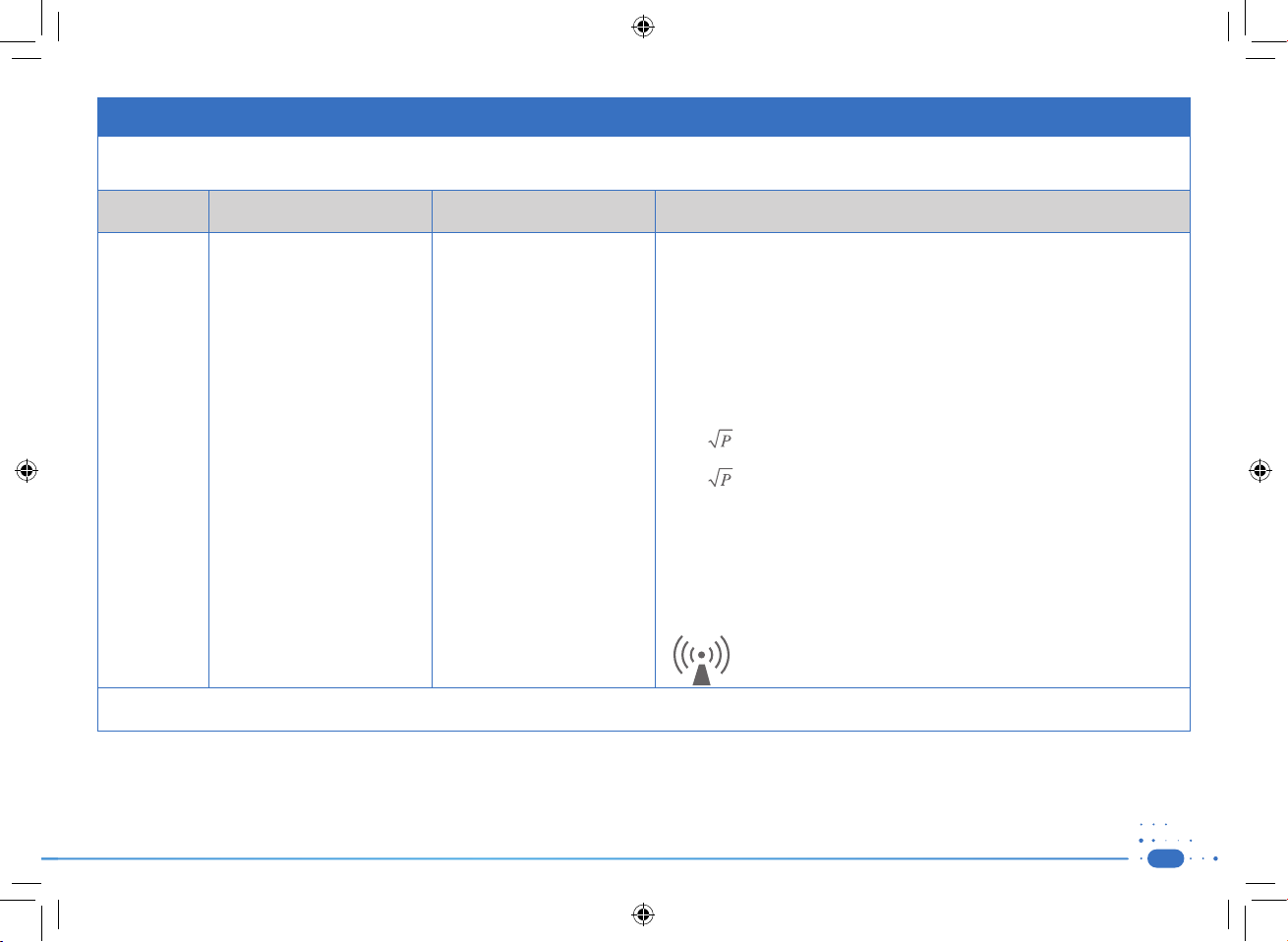
Guidance and manufacturer’s declaration – electromagnetic immunity
The STIMPOD NMS410/NMS450X is intended for use in the electromagnetic environment specified below. The customer or the user of the STIMPOD NMS 410/450X should assure that
it is used in such an environment.
Immunity
test
Conducted RF
IEC 61000-4-6
IEC 60601 test level Compliance level Electromagnetic environment – guidance
Portable and mobile RF communications equipment should be used no closer to any
part of the STIMPOD NMS 410/450X, including cables, than the recommended separation
distance calculated from the equation applicable to the frequency of the transmitter.
Recommended separation distance
3V at 0.15 - 80MHz and 6V at ISM
Frequency. Home Healthcare: 3V at
0.15-80MHz, and 6V at ISM and Ra
dio Amateur Frequency.
3V at 0.15 - 80MHz and 6V at ISM
Frequency. Home Healthcare: 3V at
-
0.15-80MHz, and 6V at ISM and Radio Amateur Frequency.
Radiated RF
IEC 61000-4-3
3 V/m (10V/m Home Healthcare) at
80-2,700MHz, AM Modulation. And
9-28V/m at 385-6000MHz, Pulse
Mode and other Modulation (upon
Risk Analysis).
3 V/m (10V/m Home Healthcare) at
80-2,700MHz, AM Modulation. And
9-28V/m at 385-6000MHz, Pulse
Mode and other Modulation (upon
Risk Analysis).
d = 1,2 80 MHz to 800 MHz
d = 2,3 800 MHz to 2,5 GHz
where P is the maximum output power rating of the transmitter in watts (W) according
to the transmitter manufacturer and d is the recommended separation distance in metres
(m).
Field strengths from fixed RF transmitters, as determined by an electromagnetic site
survey,a should be less than the compliance level in each frequency range.
Interference may occur in the vicinity of equipment marked with the
following symbol:
NOTE 1 At 80 MHz and 800 MHz, the higher frequency range applies.
NOTE 2 These guidelines may not apply in all situations. Electromagnetic propagation is affected by absorption and reflection from structures, objects and people.
a
Field strengths from fixed transmitters, such as base stations for radio (cellular/cordless) telephones and land mobile radios, amateur radio, AM and FM radio broadcast and TV broadcast
cannot be predicted theoretically with accuracy. To assess the electromagnetic environment due to fixed RF transmitters, an electromagnetic site survey should be considered. If the
measured field strength in the location in which the STIMPOD NMS 410/450X is used exceeds the applicable RF compliance level above, the STIMPOD NMS 410/450X should be
observed to verify normal operation. If abnormal performance is observed, additional measures may be necessary, such as re-orienting or relocating the STIMPOD NMS 410/450X.
5

Recommended separation distances between portable and mobile RF communications equipment and
the STIMPOD NMS410/450X
The STIMPOD NMS 410/450X is intended for use in an electromagnetic environment in which radiated RF disturbances are controlled. The customer or the user of the STIMPOD NMS
410/450X can help prevent electromagnetic interference by maintaining a minimum distance between portable and mobile RF communications equipment (transmitters) and the
STIMPOD NMS 410/450X as recommended below, according to the maximum output power of the communications equipment.
Separation distance according to frequency of transmitter
Rated maximum output power
W
0,01 - 0,12 0,23
0,1 - 0,38 0,73
1 - 1,2 2,3
10 - 3,8 7,3
100 - 12 23
For transmitters rated at a maximum output power not listed above, the recommended separation distance d in metres (m) can be estimated using the equation applicable to the
frequency of the transmitter, where P is the maximum output power rating of the transmitter in watts (W) according to the transmitter manufacturer.
NOTE 1 At 80 MHz and 800 MHz, the separation distance for the higher frequency range applies.
NOTE 2 These guidelines may not apply in all situations. Electromagnetic propagation is affected by absorption and reflection from structures, objects and people.
150 kHz to 80 MHz
Not applicable
m
80 MHz to 800 MHz
d = 1,2
800 MHz to 2,5 GHz
d = 2,3
Guidance and manufacturers declaration – electromagnetic immunity – for equipment and systems that are non- life supporting
The STIMPOD NMS 410/450X is intended for use in the electromagnetic environment specified below. The customer or the user of the STIMPOD NMS 410/450X should assure that it
is used in such an environment
Immunity Test IEC 60601 test level Compliance level Electromagnetic environment - guidance
Radiated immunity
80MHz - 2.5GHz
6
80MHz – 1GHz @ 3V/m & 10V/m
1GHz – 2.5GHz @ 10V/m
80MHz – 1GHz @ 3V/m & 10V/m
1GHz – 2.5GHz @ 10V/m
Portable and mobile RF communications equipment can affect MEDICAL
ELECTRICAL EQUIPMENT and should be used no closer to any part of the
equipment, including cables, than the recommended separation distance.
Contents
1. Getting to know the STIMPOD (NMS 410/450X) 8
1.1) Device Description 8
1.2) Accessories 9
1.3) Device Layout 10
1.4) Screen Layout 11
1.5) Warning Screens 12
1.6) Open Circuit Detection 14
1.7) Auto Shutdown 14
1.8) Symbols 14
2. Nerve Locating/Mapping Mode (NMS 410/450X) 15
2.1a) Adjusting the Current in LOC mode 16
2.1b) Adjusting the Current in MAP mode 17
2.2) Adjusting the Pulse Width 18
2.3) Proximity Indicator 18
2.4) Adjusting the Twitch Frequency 18
3. Neuromuscular Transmission (NMT)
Monitoring Mode (NMS 450X) 19
3.1) Adjusting the Current 21
3.2) Adjusting Stimulation Mode 21
3.3) Adjusting the Twitch/ Tetanus Frequency 21
3.4) Train of Four Mode (TOF) 22
3.5) Double Burst Mode (DB) 22
3.6) Post Tetanic Count Mode (PTC) 23
3.7) Supra Maximal Current Mode (SMC) 23
3.8) Auto Mode 24
3.9) Twitch Mode 25
3.10) Tetanus Mode 25
4. Setting up Device Defaults 26
4.1) Setup Menu 27
4.2) User Settings 27
4.3) NMT Settings 28
4.4) Locate Settings 29
5. Technical Notes 31
5.1) Performance Testing 31
5.2) Specifications 34
5.3) Cleaning and Disinfecting STIMPOD 34
Products & Accessories 35
7
1
Getting to Know the STIMPOD
(NMS 410/450)
1.1) Device Description
The STIMPOD NMS 450X is quantitative Neuromuscular Transmission (NMT) Monitor which provides real-time quantitative feedback utilizing tri-axial accelerometry.
The Stimpod NMS 410 as well as Stimpod NMS 450X is also a precision nerve locating tool used for localizing specific neural pathways. Localization of nerves by electrical stimulation
involves connecting the nerve stimulator to a conducting needle through which local anaesthetics can be injected. The distance of the needle (cathode) from the nerve can be estimated
by establishing the minimum threshold current required, to facilitate a neuromuscular response.
CAUTION: This device should only be used by a qualified physician with appropriate knowledge in anaesthesia.
The sale or purchase of the device is restricted to licensed medical practitioners, as governed by the law of the country/state in which he/she practices, or where the device is
to be used.
8
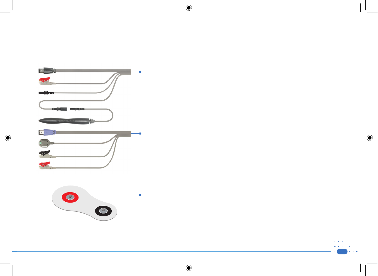
1.2) Accessories
WARNING: Use of cables or other accessories other than those supplied with the STIMPOD may result in serious injury.
NOTE: Electrodes and Nerve Locating needles are not included in this package.
CAUTION: A sterile wipe should be applied to the Nerve Mapping Probe prior to use.
Nerve Mapping/ Nerve Locating Cable (XT-41014):
• This cable is used to activate the Nerve Mapping/ Nerve Locating mode on the STIMPOD.
• The red (anode) connector is designed to clip on to a standard ECG electrode.
• The ergonomically designed cutaneous Nerve Mapping Probe presents the user with a simple and reliable
Nerve Mapping solution.
• The 2mm needle connector will accommodate various makes of needles.
NMT Monitoring Cable (NMS 450X) (XT-45025):
• This cable is used to activate the NMT mode on the STIMPOD.
• The red (anode) and black (cathode) connectors are designed to clip onto the Xavant NMT electrode (XT-45008)
or onto a standard ECG electrode.
• The accelerometer is designed to attach to the contracted appendage (in the case of the ulnar nerve, this will
be the thumb).
NMT Electrode (XT-45008):
• The colour coded connections indicate the polarity for the NMT cable connections
• The larger surface area of the red (anode) electrode reduces the current density of the anode and prevents
hyperpolarization
• The proprietary gel and gel interface was specifically designed for transmission of large currents.
9
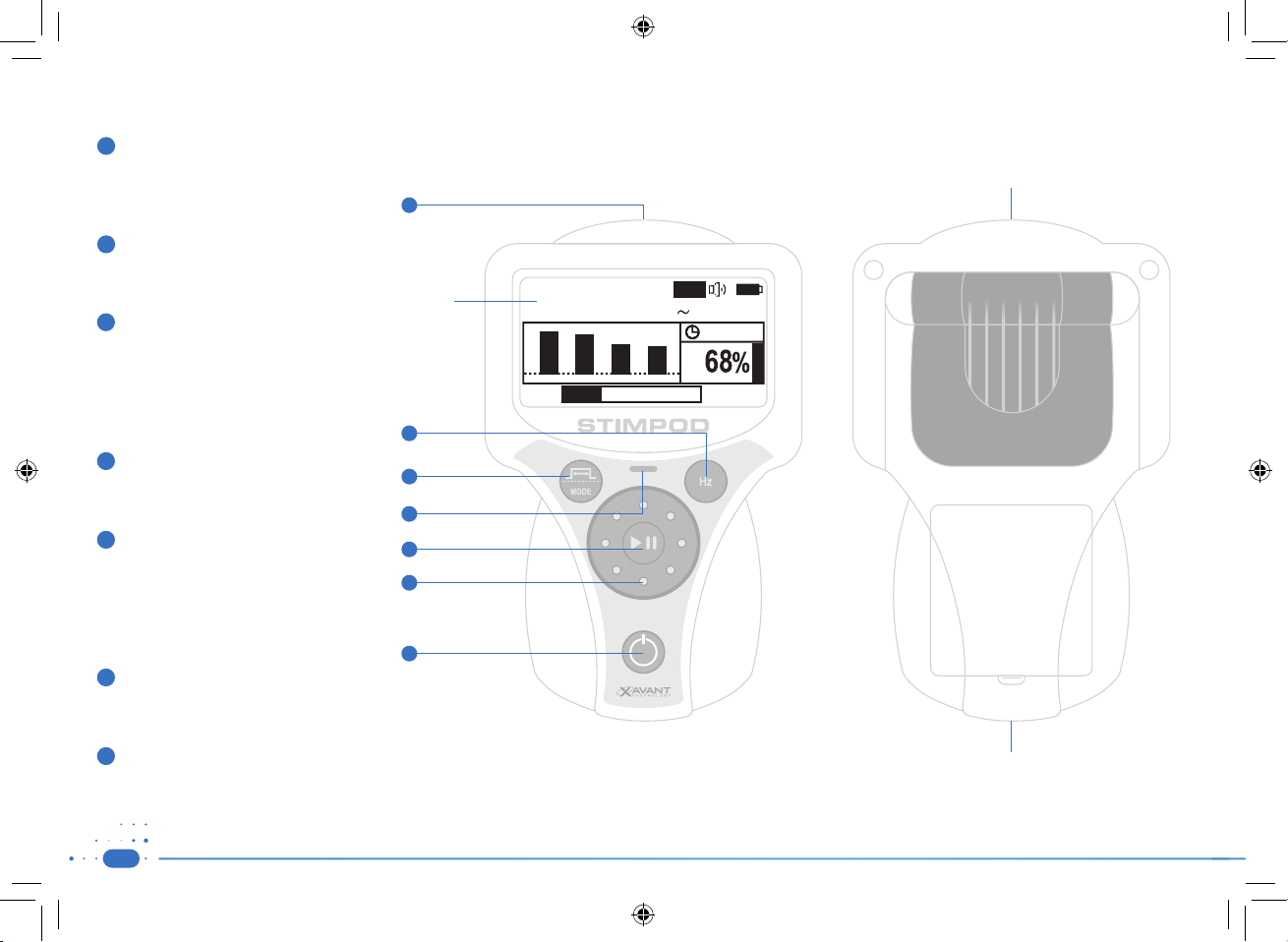
1.3) Device Layout
1
Cable Connector
Insert the combined Nerve Mapping / Locating
Cable or the NMT cable to activate the relevant
mode.
2
Enter / Frequency Button
Press to toggle between Frequencies.
Press to Enter in setup menu.
3
Menu / Pulse Width Button
NMS 410/450X (LOC/MAP Mode)
Press to toggle between Pulse Widths.
Press and hold to access Setup Menu.
NMS 450X (NMT Mode)
Press to toggle between Stimulation Modes.
4
Stimulating LED indicator
Flashing Green: Stimulus delivered.
Flashing Red: Open Circuit.
5
Pause Button
NMS 410/450X (LOC/MAP Mode)
Press to Stop / Start Stimulation.
NMS 450X (NMT Mode)
Press and release to elicit a single stimulation.
Press and hold to activate a repeated stimulation.
6
The Wheel
Adjust current in the main operating mode.
Navigate the Setup Menus.
1
Display
2
3
4
5
6
7
30mA
Aut o
u
n
e
m
Minima l
NMS 450X
NM T
30.21mA
00:15
Multi Functional Clip
T
O
F
e
n
t
e
r
7
On / O Button
Press to switch unit on / off.
10
Battery Compartment Cover
m
r
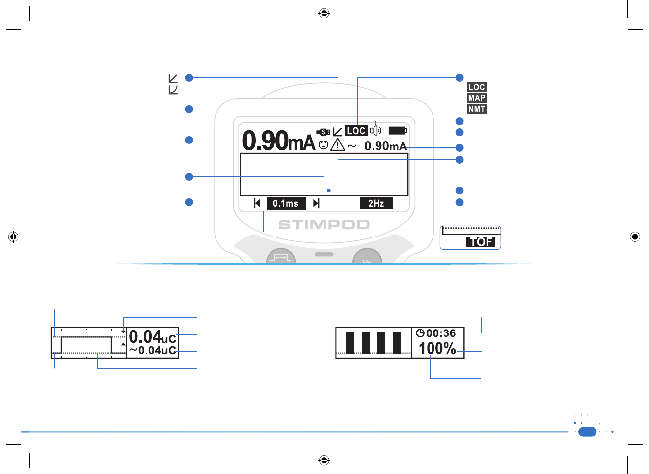
1.4) Screen Layout
Linear mode
Non-Linear mode
1
Current Mode
6
Nerve locating mode
Nerve mapping mode
Data Cable
Current Setting
Adjust using wheel
Facial Mode
Pulse Width Setting
Adjust using Menu / Pulse width button
2
7
8
3
9
10
4
11
5
u
n
e
e
n
t
e
12
13
NMT mode (NMS450X)
Speaker Volume
Battery Status
Average current of actual stimulus
Warning: Notifies the user of a discrepancy
between current setting and average
current of actual stimulus.
Diagnostic or Warning screens
Stimulating Frequency Setting
Adjust using Enter / Hz width button
NMT Mode (NMS450X)
Stimulation mode TOF, DB, PTC,
TET, TWI, SMC and Auto
Diagnostic Screen NMS 410/450X (LOC / MAP Mode) Diagnostic Screen NMS 450X (NMT Mode)
• Indication of
current setting
• 0 mA
• Proximity indicator arrow
• Calculated Charge Setting
• Average charge of actual stimulus
• Graph indicating shape of actual
current stimulus
• Real-time feedback of relative contraction
strength measured with the accelerometer
• Countdown timer for repeat mode
• Calculated percentage in TOF and DB
mode
• Twitch Count in PTC and TOF if less
than 4 contractions were identified
11
 Loading...