

Xantrex XW-SCP 865-1050 Owner's Manual
Fault/Warning
System Control Panel II
XW System
Control Panel
Standby
Owner’s Guide


XW System Control Panel
Owner’s Guide

About Xantrex
Xantrex Technology Inc. is a world-leading supplier of advanced power electronics and controls with
products from 50 watt mobile units to one MW utility-scale systems for wind, solar, batteries, fuel cells,
microturbines, and backup power applications in both grid-connected and stand-alone systems. Xantrex
products include inverters, battery chargers, programmable power supplies, and variable speed drives
that convert, supply, control, clean, and distribute electrical power.
Trademarks
XW System Control Panel is a trademark of Xantrex International. Xantrex and Xanbus are registered
trademarks of Xantrex International.
Other trademarks, registered trademarks, and product names are the property of their respective owners
and are used herein for identification purposes only.
Notice of Copyright
XW System Control Panel Owner’s Guide © May 2007 Xantrex International. All rights reserved.
Exclusion for Documentation
UNLESS SPECIFICALLY AGREED TO IN WRITING, XANTREX TECHNOLOGY INC. (“XANTREX”)
(
A) MAKES NO WARRANTY AS TO THE ACCURACY, SUFFICIENCY OR SUITABILITY OF ANY TECHNICAL OR
OTHER INFORMATION PROVIDED IN ITS MANUALS OR OTHER DOCUMENTATION.
(
B) ASSUMES NO RESPONSIBILITY OR LIABILITY FOR LOSSES, DAMAGES, COSTS OR EXPENSES, WHETHER
SPECIAL, DIRECT, INDIRECT, CONSEQUENTIAL OR INCIDENTAL, WHICH MIGHT ARISE OUT OF THE USE OF
SUCH INFORMATION. THE USE OF ANY SUCH INFORMATION WILL BE ENTIRELY AT THE USER’S RISK; AND
(C) REMINDS YOU THAT IF THIS MANUAL IS IN ANY LANGUAGE OTHER THAN ENGLISH, ALTHOUGH
STEPS HAVE BEEN TAKEN TO MAINTAIN THE ACCURACY OF THE TRANSLATION, THE ACCURACY CANNOT
BE GUARANTEED. APPROVED XANTREX CONTENT IS CONTAINED WITH THE ENGLISH LANGUAGE
VERSION WHICH IS POSTED AT WWW.XANTREX.COM.
Date and Revision
May 2007 Revision A
Pa rt Number
975-0298-01-01
Product Number
865-1050
Contact Information
Telephone: 1 800 670 0707 (toll free North America)
1 360 925 5097 (direct)
Fax: 1 800 994 7828 (toll free North America)
1 360 925 5143 (direct)
Email: customerservice@xantrex.com
Web: www.xantrex.com

About This Guide
Purpose
The purpose of this Owner’s Guide is to provide explanations and
procedures for installing and operating the XW System Control Panel.
Scope
The Guide provides safety guidelines, setup information, and procedures
for installing and configuring the XW System Control Panel. This Guide
also includes information about operating and troubleshooting the unit.
This Guide does not contain guidelines for configuring every Xanbusenabled device to which the System Control Panel connects. See the
owner’s guide or operation guide for each Xanbus-enabled device for
detailed configuration information.
Firmware Revision
Some System Control Panel features and functions described in this
manual may be incompatible with later firmware revisions. To view the
firmware revision number of your product, see “Viewing Device
Information” on page 3–14.
Audience
The Guide is intended for anyone who needs to install and/or operate the
System Control Panel. Installers should be certified technicians or
electricians.
Organization
This Guide is organized into five chapters and one appendix.
Chapter 1, “Introduction”, introduces and describes features of the
Xantrex System Control Panel.
Chapter 2, “Installation”, contains information and procedures for
installing the System Control Panel.
iii
About This Guide
Chapter 3, “Configuration”, contains information and procedures for
configuring the System Control Panel and using the System Control Panel
to configure another device.
Chapter 4, “Operation”, contains information and procedures for
operating the System Control Panel.
Chapter 5, “Troubleshooting”, contains reference tables of warning and
fault messages.
Appendix A, “Specifications”, contains the electrical, mechanical, and
environmental specifications for the System Control Panel.
Conventions Used
The following conventions are used in this guide.
WARNING
Warnings identify conditio ns or practices that could result in personal injury or
loss of life
CAUTION
Cautions identify conditions or practices that could result in damage to the unit or
other equipment.
Important:
but is not as critical as a caution or warning.
Related Information
For more information about related products, refer to:
XW Series Hybrid Inverter/Charger Operation Guide (975-0240-01-01)
XW Series Solar Charge Controller Owner’s Manual (975-0283-01-01)
XW Automatic Generator Start Owner’s Guide (975-0307-01-01)
You can find more information about Xantrex Technology Inc. as well as
its products and services at www.xantrex.com.
These notes contain information that is important for you to know,
iv 975-0298-01-01
Important Safety Instructions
WARNING: Save these instructions
This Owner’s Guide contains important safety and operating instructions.
Before using your XW System Control Panel, be sure to read, understand, and
save these safety instructions.
General Precautions
1. Before installing and using this device, read all appropriate sections
of this guide and any cautionary markings on the System Control
Panel and the devices to which it connects.
2. If the System Control Panel has been damaged, see “Warranty and
Return Information” on page WA–1.
3. Do not dismantle the System Control Panel; it contains no userserviceable parts. See “Information About Your System” on
page WA–5 for instructions on obtaining service.
4. Protect the System Control Panel from rain, snow, spray, and water.
Explosive Gas Precautions
WARNING: Explosion hazard
This equipment is not ignition protected. To prevent fire or explosion, do not
install the System Control Panel in compartments containing flammable
materials or in locations that require ignition-protected equipment. This includes
any space containing gasoline-powered machinery, fuel tanks, as well as joints,
fittings, or other connections between components of the fuel system.
v

FCC Information to the User
This equipment has been tested and found to comply with the limits for a
Class B digital device, pursuant to part 15 of the FCC Rules. These limits
are designed to provide reasonable protection against harmful
interference when the equipment is operated in a residential environment.
This equipment generates, uses and can radiate radio frequency energy
and, if not installed and used in accordance with the instruction guide,
may cause harmful interference to radio communications. However , there
is no guarantee that interference will not occur in a particular installation.
If this equipment does cause harmful interference to radio or television
reception, which can be determined by turning the equipment off and on,
the user is encouraged to try to correct the inte rfe re nc e by one or more of
the following measures:
• Reorient or relocate the receiving antenna.
• Increase the separation between the equipment and the receiver.
• Connect the equipment to a different circuit from that to which the
receiver is connected.
• Consult the dealer or an experienced radio/TV technician for help.
vi 975-0298-01-01

Contents
Important Safety Instructions
1
Introduction
About the XW System Control Panel- - - - - - - - - - - - - - - - - - - - - - - - - - - - - - - - - 1–2
Physical Features - - - - - - - - - - - - - - - - - - - - - - - - - - - - - - - - - - - - - - - - - - - - - - 1–3
Front Panel Features - - - - - - - - - - - - - - - - - - - - - - - - - - - - - - - - - - - - - - - - -1–3
Back Panel Features - - - - - - - - - - - - - - - - - - - - - - - - - - - - - - - - - - - - - - - - - 1–4
System Components - - - - - - - - - - - - - - - - - - - - - - - - - - - - - - - - - - - - - - - - - - - - 1–4
2
Installation
Installing the XW System Control Panel- - - - - - - - - - - - - - - - - - - - - - - - - - - - - - - 2–2
Materials and Tools Required - - - - - - - - - - - - - - - - - - - - - - - - - - - - - - - - - - - 2–2
Choosing a Location - - - - - - - - - - - - - - - - - - - - - - - - - - - - - - - - - - - - - - - - -2–2
Network Installation - - - - - - - - - - - - - - - - - - - - - - - - - - - - - - - - - - - - - - - - - - - - 2–3
Network Components - - - - - - - - - - - - - - - - - - - - - - - - - - - - - - - - - - - - - - - -2–3
Ordering Network Components - - - - - - - - - - - - - - - - - - - - - - - - - - - - - - - - - 2–6
Network Layout - - - - - - - - - - - - - - - - - - - - - - - - - - - - - - - - - - - - - - - - - - - -2–6
Guidelines for Routing the Xanbus Cables - - - - - - - - - - - - - - - - - - - - - - - - - -2–8
Connecting Xanbus Cables - - - - - - - - - - - - - - - - - - - - - - - - - - - - - - - - - - - -2–9
- - - - - - - - - - - - - - - - - - - - - - - - - - - - - - - - - - -v
Mounting the System Control Panel- - - - - - - - - - - - - - - - - - - - - - - - - - - - - - - - - 2–11
Verifying the Installation - - - - - - - - - - - - - - - - - - - - - - - - - - - - - - - - - - - - - - - - 2–15
3
Configuration
Configuration Using the System Control Panel - - - - - - - - - - - - - - - - - - - - - - - - - - 3–2
Using System Control Panel Buttons - - - - - - - - - - - - - - - - - - - - - - - - - - - - - - 3–2
Reading Screens and Menus - - - - - - - - - - - - - - - - - - - - - - - - - - - - - - - - - - - -3–2
Changing Settings for a Device - - - - - - - - - - - - - - - - - - - - - - - - - - - - - - - - -3–5
Configuring the XW System Control Panel- - - - - - - - - - - - - - - - - - - - - - - - - - - - - 3–7
System Control Panel Configuration Items - - - - - - - - - - - - - - - - - - - - - - - - - - 3–8
Setting the Device Name - - - - - - - - - - - - - - - - - - - - - - - - - - - - - - - - - - - - - -3–9
Using the Clock Menu- - - - - - - - - - - - - - - - - - - - - - - - - - - - - - - - - - - - - - - - - - 3–10
Clock Menu Configuration Items - - - - - - - - - - - - - - - - - - - - - - - - - - - - - - - 3–10
975-0298-01-01 vii

Contents
Setting the Time - - - - - - - - - - - - - - - - - - - - - - - - - - - - - - - - - - - - - - - - - - 3–11
Setting the Date - - - - - - - - - - - - - - - - - - - - - - - - - - - - - - - - - - - - - - - - - - - 3–12
Using the System Settings Menu- - - - - - - - - - - - - - - - - - - - - - - - - - - - - - - - - - - 3–12
System Settings Menu Configuration Items - - - - - - - - - - - - - - - - - - - - - - - - 3–13
Using Cascading Parameters - - - - - - - - - - - - - - - - - - - - - - - - - - - - - - - - - - 3–14
Viewing Device Information - - - - - - - - - - - - - - - - - - - - - - - - - - - - - - - - - - 3–14
4
Operation
System Modes - - - - - - - - - - - - - - - - - - - - - - - - - - - - - - - - - - - - - - - - - - - - - - - - 4–2
Changing System Modes - - - - - - - - - - - - - - - - - - - - - - - - - - - - - - - - - - - - - - 4–2
Operating Mode - - - - - - - - - - - - - - - - - - - - - - - - - - - - - - - - - - - - - - - - - - - - 4–2
Standby Mode - - - - - - - - - - - - - - - - - - - - - - - - - - - - - - - - - - - - - - - - - - - - - 4–2
Using the Standby Button - - - - - - - - - - - - - - - - - - - - - - - - - - - - - - - - - - - - - 4–3
Warnings and Faults - - - - - - - - - - - - - - - - - - - - - - - - - - - - - - - - - - - - - - - - - - - - 4–3
Warning Messages - - - - - - - - - - - - - - - - - - - - - - - - - - - - - - - - - - - - - - - - - - 4–3
Fault Messages - - - - - - - - - - - - - - - - - - - - - - - - - - - - - - - - - - - - - - - - - - - - 4–6
5
Troubleshooting
Troubleshooting Reference - - - - - - - - - - - - - - - - - - - - - - - - - - - - - - - - - - - - - - - 5–2
Types of Faults and Warnings - - - - - - - - - - - - - - - - - - - - - - - - - - - - - - - - - - 5–2
Warning Reference Table - - - - - - - - - - - - - - - - - - - - - - - - - - - - - - - - - - - - - 5–2
Fault Reference Table - - - - - - - - - - - - - - - - - - - - - - - - - - - - - - - - - - - - - - - - 5–4
A
Specifications
Electrical Specifications - - - - - - - - - - - - - - - - - - - - - - - - - - - - - - - - - - - - - - - - -A–2
Mechanical Specifications - - - - - - - - - - - - - - - - - - - - - - - - - - - - - - - - - - - - - - - -A–2
Environmental Specifications- - - - - - - - - - - - - - - - - - - - - - - - - - - - - - - - - - - - - -A–2
Warranty and Return Information
Index
- - - - - - - - - - - - - - - - - - - - - - - - - - - - - - - - - - - - - - - - - - - - - - - - - - - - - - - IX–1
- - - - - - - - - - - - - - - - - - - - - - - - - - - WA–1
viii 975-0298-01-01

1
Introduction
Chapter 1 introduces and describes operational and
physical features of the XW System Control Panel.

Introduction
About the XW System Control Panel
Complete
system control
System
component
The XW System Control Panel provides configuration and m on itoring
capability for an XW Power System. The System Control Panel:
• Monitors activity throughout your power system
• Displays the settings and status of each Xanbus-enabled device
• Enables you to adjust settings for each Xanbus-enabled device.
The System Control Panel uses Xanbus™, a network communications
protocol developed by Xantrex, to communicate its settings and activity
to other Xanbus-enabled devices.
Xanbus-enabled products are:
• Easy to use. The Xanbus network simplifies operation and automates
routine tasks.
• Reliable. Software control eliminates errors due to analog signaling.
• Accurate. Digital information is less susceptible to interference and
line loss.
Important:
System components, including XW Hybrid Inverter/Chargers, XW-MPPT
Charge Controllers, and the XW Automatic Generator Start.
The XW System Control Panel is compatible only with XW
System
requirements
Operational
Features
The System Control Panel requires a Xanbus power supply to operate.
Network power is carried by the network cables, and can be supplied by
an XW Hybrid Inverter/Charger or an external Xanbus power supply.
As a device that draws network power, the System Control Panel
consumes a maximum of 3 watts.
Other features of the System Control Panel include:
• Compatibility—connect additional Xanbus-enabled XW System
devices without requiring additional device-specific control panels.
• Internal clock—keeps time for the entire system.
• Audible alarm—if enabled, alerts you when a fault condition arises.
• Low power consumption—automatically turns off the backlight after
a period of inactivity.
• Non-volatile memory—preserves System Control Panel settings if
network power is interrupted or network communication is disrupted.
1–2 975-0298-01-01
Physical Features
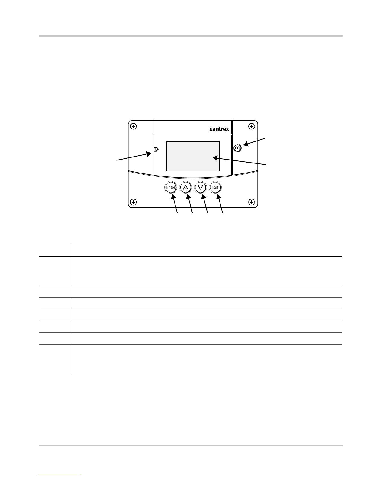
See Figure 1-1 and Figure 1-2 for the front and back features of the
System Control Panel.
Front Panel Features
Fault/Warning
Physical Features
7
Standby
1
Figure 1-1
System Control Panel II
2345
Front Panel
6
Feature
1 Fault/Warning light indicates a device has a fault or warning condition and requires
attention. The light flashes when a warning occurs, and turns on steadily when a fault
occurs.
2 Enter button confirms selection of a menu item or displays the next screen.
3 Up arrow butto n scrolls upwards through screen text or increases a selected value.
4 Down arrow button scrolls downwards through screen text or decreases a selected value.
5 Exit button cancels selection of a menu item or displays the previous screen.
6 Screen shows menus, settings, and system information.
7 Standby button disables inverting and charging on all inverter/chargers in the system
when pressed for one to two seconds. To enable inverting and charging, press the Standby
button again. See “Using the Standby Button” on page 4–3.
975-0298-01-01 1–3
Introduction
Back Panel Features
T wo Xanbus network inputs on the back panel let you connect the Syst em
Control Panel to other Xanbus-enabled devices. See Figure 1-2.
Xanbus network inputs (8-pin RJ-45)
Figure 1-2
Back Panel
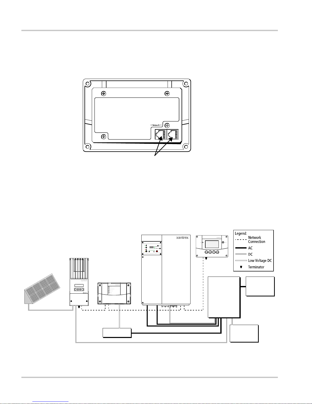
System Components
The Xanbus system (Figure 1-3) includes the System Control Panel and
other Xanbus-enabled devices.
Charge
Controller
PV Array
Automatic Generator Start
Enter Exit
Solar Charge Controller
Inverter/Charger
Grid(A C1)
Gen(AC2)
Fault/
Warning
Equalize
Battery
AC Out DC In/OutAC In
Inverting
Flashing= sell
Charging
Hybrid Inverter/Charger
System Control Panel
AC Panel
Distribution
Panel
Figure 1-3
Network Diagram
1–4 975-0298-01-01
BatteryGenerator

2
Installation
Chapter 2 contains information and procedures for
planning and performing a XW System Control Panel
installation, including:
• Materials and tools required
• Choosing a location
• Choosing a network layout
• Mounting the unit
• Connecting the System Control Panel to other
devices.

Installation
Installing the XW System Control Panel
The XW System Control Panel is designed to be wall moun ted (see
“Mounting the System Control Panel” on page 2–11), and requires no
connections other than Xanbus ne twork cables o r a terminator plug ged into
the back of the unit.
Because you cannot access the System Control Panel network inputs once
the unit is mounted, the Xanbus cables must be routed through the wall
and connected before securing the System Control Panel.
Materials and Tools Required
The following materials and tools are required to complete the
installation:
p Mounting template sticker (supplied)
p Mounting plate (supplied)
p Mounting bracket (supplied)
p Four #6 screws (supplied)
p Two #8 screws (supplied)
p Cable clamps or hardware fasteners
p Xanbus network cables or equivalent (CAT 5 or CAT 5e cable with
RJ-45 connectors wired to T568A standard. One 7 foot/2.1 meter
cable is supplied)
p Two network terminators (one male terminator is supplied with each
Xanbus-enabled device, but termination requirements vary with
network layout)
p Phillips head screwdriver
p Jigsaw or small keyhole saw
p Power drill with 1/8" bit (optional)
Choosing a Location
Choose a location that allows unobstructed access to the System Control
Panel screen and buttons.
The location should be indoors, dry, and free from corrosive or explosive
fumes.
2–2 975-0298-01-01
WARNING: Explosion hazard
The System Control Panel is not Ignition Protected. Do not install in areas
requiring Ignition-Pr ot ected equipment, such as areas containing gasoline
engines, tanks, or fuel-line fittings.
Network Installation
This section describes requirements for installing the System Control
Panel as part of a Xanbus network-managed power system. For the
system to function properly, requirements for network layout and
termination must be followed.
Network Components
A Xanbus network consists of the following components:
Network Installation
• Xanbus-enabled devices—these include the System Control Panel,
the XW Series Inverter/Charger, XW-Automatic Generator Start
(AGS), and XW Charge Controller. The network can consist of up to
eight Xanbus-enabled devices. A typical XW Power System can
include three inverter/chargers, two charge controllers, one AGS and
one System Control Panel. Only one System Control Panel can be
installed on the Xanbus network.
• Xanbus power supply—the network requires a power supply ca pable
of providing 15 Vdc/200 mA to each device. The XW Series Inverter/
Charger provides network power, but if no inverter/charger is
installed, an external power supply is required. Contact Xantrex for
more information.
• Xanbus cables—each Xanbus-enabled device is connected by a
Category 5 (CAT 5 or CAT 5e) cable. The cable consists of eight
conductors in four twisted pairs with an RJ-45 modular connector
wired to the T568A standard. See Figure 2-2 on page 2–4. A 7 foot
(2.1 meter) network cable is included with the System Control Panel.
If more cables or a different length are required, these standard cables
can be purchased from Xantrex or any computer supply store.
CAUTION: Equipment damage
Do not use crossover cable.
975-0298-01-01 2–3
Installation
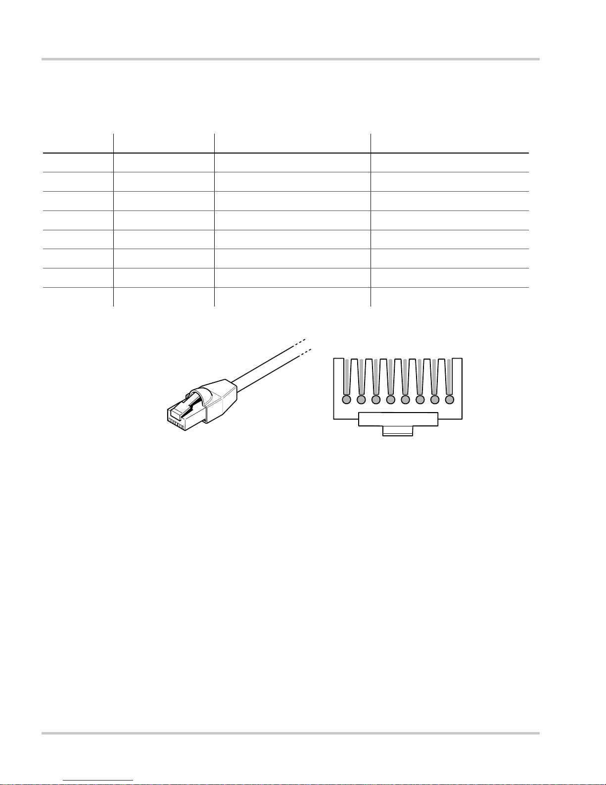
Table 2-1 contains the arrangements of wire colors to pin numbers for the
T568A standard.
Figure 2-1
Pin Number Conductor Name CAT 5 Cable Insulation Color CAT 5e Cable Insulation Color
1 NET_S White/Green White/Orange
2 NET_S Green Orange
3 NET_C White/Orange White/Green
4 CAN_L Blue Blue
5 CAN_H White/Blue White/Blue
6 NET_C Orange Green
7 NET_S White/Brown White/Brown
8 NET_C Brown Brown
T568A Standard Wiring
Pins:
8 7 6 5 4 3 2 1
Figure 2-2
RJ-45 Connector
• Network terminators (Figure 2-3)—the Xanbus network must be
properly terminated at each end with male or female network
terminators to ensure the communication signal quality on the
network. If the network is not properly terminated, signal quality is
degraded and performance on the network is reduced. Permanent
configuration without terminators is not supported by Xantrex. The
System Control Panel ships with one male terminator already
installed. Depending on your network layout, this terminator may
need to be removed and inserted into another device elsewhere in the
network.
2–4 975-0298-01-01

Network Installation
Male network terminator Female network terminator
Figure 2-3
Network Terminators
• Network connectors (optional, depending on network layout)—the
three-way connector houses three RJ-45 inputs that provide a device
connection point on a multi-drop backbone layout (see “Multi-Drop
Backbone Layout” on page 2–6). All three inputs are wired
identically and can accept either Xanbus cables or terminators. One
input is available for connecting to a Xanbus-enabled device. The
remaining inputs are reserved for connection to other network
connectors, a Xanbus cable terminated with a female terminator, or a
male terminator.
The network connector is mounted to a bulkhead or a wall, as shown
in Figure 2-4.
Figure 2-4
975-0298-01-01 2–5
To network connector
or terminator
Three-Way Network Connector
To network connector
To device
Installation
Ordering Network Components
T able 2-1 provides a partial list of network components and part numbers.
Ready-made cables are available in standard lengths from 3 feet to 75
feet.
For the most up-to-date list, call your dealer. Call your dealer or visit the
Outlet Store at www.xantrex.com to purchase cables and other network
components.
Network Layout
Table 2-1
Network Component Part Number
Network termination—Male (2 per pack) 809-0901
Network termination—Female (2 per pack) 809-0905
Three-way network connector 809-0903
Network cable 3 ft. (0.9 m) 809-0935
Network cable 5 feet (1.5 m) 809-0936
Network cable 7 feet (2.0 m) 809-0937
Network cable 10 feet (3.0 m) 809-0938
Network cable 14 feet (4.3 m) 809-0939
Network cable 25 feet (7.6 m) 809-0940
Network cable 50 feet (15.2 m) 809-0941
Network cable 75 feet (22.9 m) 809-0942
Network Components and Part Numbers
Xanbus-enabled devices can be connected in one of two Xanbus System
layouts: multi-drop backbone or daisy chain. Each network layout has
advantages and disadvantages, depending on the application and/or
environment. It is up to you or your system designer to decide which
layout is best for your installation.
Important:
configurations are not supported by Xantrex.
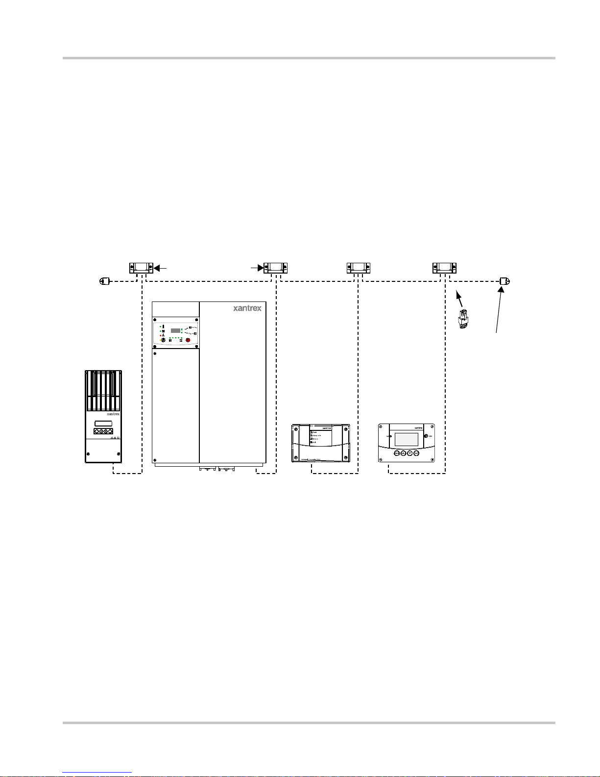
Multi-Drop Backbone Layout
In a multi-drop backbone layout, each Xanbus-enabled device on the
network is connected by a drop cable to the network bus or backbone
using a network connector, as shown in Figure 2-5.
2–6 975-0298-01-01
Do not mix the two types of network layouts. Mixed
Network Installation
Network terminators are required at both ends of the network, and the
Xanbus-enabled devices do not require their own termination.
If cables are placed at the end of the network, female terminators are
required. Otherwise, male terminators must be inserted directly into the
open input of each network connector at the end of the network.
Advantages In this layout, Xanbus-enabled devices can be removed or
replaced while still keeping the network operating.
Disadvantage The main disadvantage of this layout is the cost of the
network connectors (a daisy chain layout uses no network connectors).
Each device in this layout requires its own network connector.
3-way connectors
Inverter/Charger
Grid(A C1)
Gen(AC 2)
Fault/
Warning
Equali ze
Charge
Controller
Enter Exit
Solar Charge Control l er
Figure 2-5
Multi-Drop Backbone Layout
Daisy Chain Layout
Inverting
Flashing= sell
Charging
Battery
Terminate network
at each end with
male or female
terminators.
Automatic
Generator Start
Hybrid Inverter/Charger
System
Control Panel
System Control Panel II
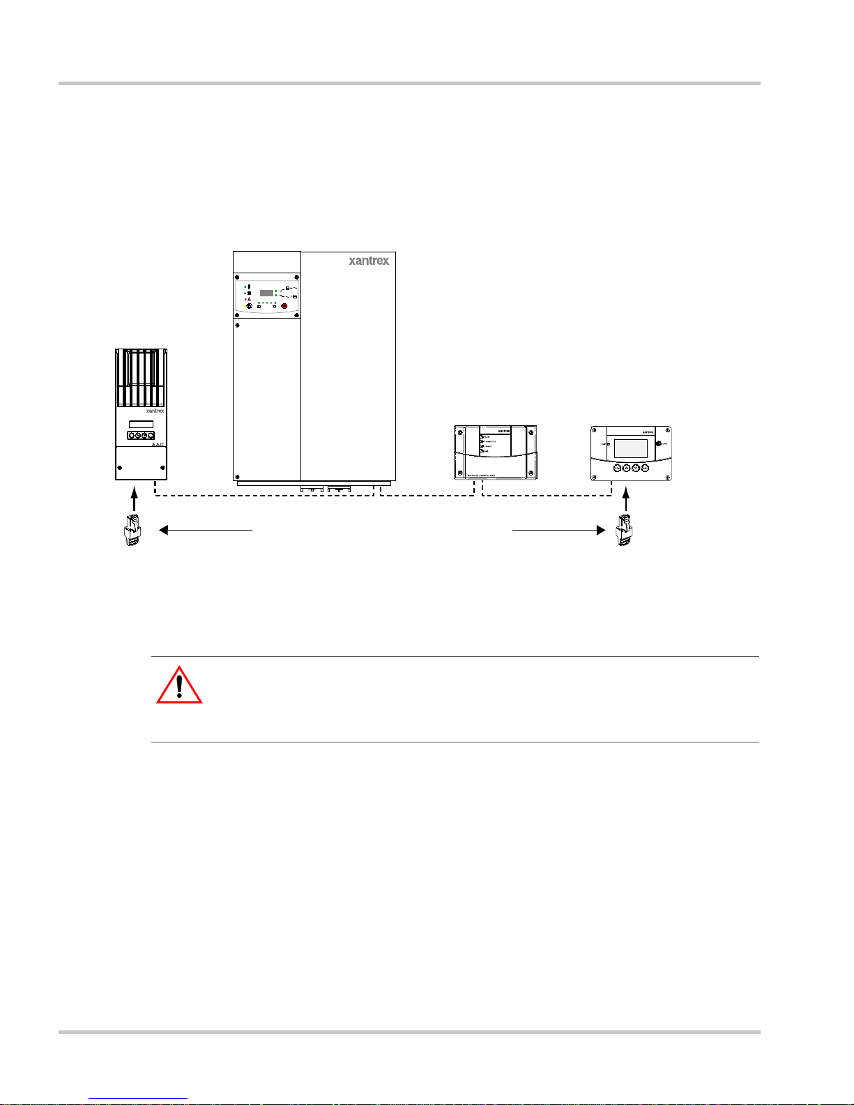
In a daisy chain layout, each device on the network is linked with separate
lengths of Xanbus cable, as shown in Figure 2-6. This layout does not
require network connectors.
As in the multi-drop backbone layout, two terminators are required to
ensure the communication signal quality on the network. The Xanbusenabled devices at each end of the chain must have a male terminator
inserted into their open network inputs.
Advantage The advantage of this layout is that it is less expensive to
install because network connectors are not required.
975-0298-01-01 2–7
Installation
Disadvantage The disadvan tag e of the daisy chain layout is that
Xanbus-enabled devices cannot be removed from the network without
interrupting the network. To make the network function after removing a
device, you must connect the Xanbus-enabled devices on either side of
the missing device to each other or replace the device.
Inverter/Charger
Charge
Controller
Enter Exit
Solar Charge Control l er
Grid(A C1)
Gen(AC 2)
Fault /
Warning
Equalize
Inverting
Flashing= sell
Chargi ng
Battery
Automatic Generator Start
HybridInverter/Charger
Terminate the network at each end.
Figure 2-6
Daisy Chain Layout
Guidelines for Routing the Xanbus Cables
WARNING: Shock hazard
System Control Panel
System Control Panel II
:
Do not route the Xanbus cables in the same conduit or panel as the AC and DC
power cabling.
To ensure maximum performance of your network, follow these
guidelines when routing the Xanbus cables. Route the cables before
installing the System Control Panel.
• Route the cables away from sharp edges that might damage the
insulation. Avoid sharp bends in the cable—no less than a 4-inch
(100 mm) radius.
• Allow at least 2 ¼ inches (57 mm) of space behind the wall to
accommodate the depth of the unit and allow room for the cables to
bend.
• Allow for some slack in the cable tension.
2–8 975-0298-01-01
• Keep the alignment of wire pairs inside the sheath as straight as
possible.
• Allow separation between data and power cables (data cables should
only cross a power cable at right angles).
• Do not staple the cable with metal cable staples. Use appropriate
hardware fasteners to avoid damage to the cable.
The total length of the network, including all connected Xanbus-enab l ed
devices and the System Control Panel, cannot exceed 130 feet (40 m).
Xanbus cables are available in lengths from 3 feet (0.9 m) to 75 feet
(22.9 m).
Connecting Xanbus Cables
Follow these guidelines for connecting Xanbus cables to the System
Control Panel. The cables are connected to the System Control Panel at
the same time the System Control Panel is mounted. Read “Mounting the
System Control Panel” on page 2–11 before performing the following
procedures.
Network Installation
CAUTION: Equipment damage
:
Connect the System Control Panel only to other Xanbus-enabled devices.
Although the cabling and connectors used in this network system are the same as
Ethernet connectors, this network is not an Ethernet system. Equipment
damage may result from connecting a Xanbus system directly to a personal
computer.
CAUTION:
Do not connect one end of the network to the other to make a ring or loop.
Unpredictable device behavior
975-0298-01-01 2–9
 Loading...