

Page 1
SolarSurveyor_RevA.book Page i Friday, December 1, 2006 4:32 PM
Smart choice for power
Solar Charge
Controller
XW-MPPT-60-150
Owner’s Manual
T
F
A
DR
www.xantrex.com
Manual Type
Page 2
SolarSurveyor_RevA.book Page ii Friday, December 1, 2006 4:32 PM
Page 3
SolarSurveyor_RevA.book Page i Friday, December 1, 2006 4:32 PM
Solar Charge Controller
Owner’s Guide
Page 4

SolarSurveyor_RevA.book Page ii Friday, December 1, 2006 4:32 PM
About Xantrex
Xantrex T e chnology Inc. is a world-leadin g su pplier of advanced p ower electronics
and controls with pr oducts f rom 50 wa tt mobil e units to 1 MW ut ility-s cale syste ms
for wind, solar, batteries, fuel cells, microturbines, and backup power applications
in both grid-connected and stand-alone systems. Xantrex products include
inverters, battery chargers, programmable power supplies, and variable speed
drives that convert, supply, control, clean, and distribute electrical power.
Trademarks
Xantrex is a registered trademark of Xantrex International.
Other trademarks, registered trademarks, and product names are the property of
their respective owners and are used herein for identification purposes only.
Notice of Copyright
Solar Charge Controller Owner’s Manual © December 2006 Xantrex
International. All rights reserved.
Exclusion for Documentation
UNLESS SPECIFICALLY AGREED TO IN WRITING, XANTREX TECHNOLOGY INC.
(“XANTREX”)
(
A) MAKES NO WARRANTY AS TO THE ACCURACY, SUFFICIENCY OR SUITABILITY
OF ANY TECHNICAL OR OTHER INFORMATION PROVIDED IN ITS MANUALS OR
OTHER DOCUMENTATION.
(
B) ASSUMES NO RESPONSIBILITY OR LIABILITY FOR LOSSES, DAMAGES, COSTS OR
EXPENSES, WHETHER SPECIAL, DIRECT, INDIRECT, CONSEQUENTIAL OR
INCIDENTAL, WHICH MIGHT ARISE OUT OF THE USE OF SUCH INFORMATION. THE
USE OF ANY SUCH INFORMATION WILL BE ENTIRELY AT THE USER’S RISK; AND
(C) REMINDS YOU THAT IF THIS MANUAL IS IN ANY LANGUAGE OTHER THAN
ENGLISH, ALTHOUGH STEPS HAVE BEEN TAKEN TO MAINTAIN THE ACCURACY OF
THE TRANSLATION, THE ACCURACY CANNOT BE GUARANTEED. APPROVED
X
ANTREX CONTENT IS CONTAINED WITH THE ENGLISH LANGUAGE VERSION
WHICH IS POSTED AT www.xantrex.com.
Date and Revision
December 2006 Revision A
Part Number
975-0283-01-01 Rev A5 DRAFT
Product Number
865-1030
Contact Informatio n
Telephone: 1 800 670 0707 (toll free North America)
Fax: 1 360 925 5143 (direct)
Email: customerservice@xantrex.com
Web: www.xantrex.com
1 360 925 5097 (direct)
Page 5
SolarSurveyor_RevA.book Page iii Friday, December 1, 2006 4:32 PM
About This Guide
Purpose
The purpose of this Guide is to provide explanations and
procedures for installing, configuring, operating,
maintaining, and troubleshooting the Solar Charge
Controller.
Scope
This Guide provides safety guidelines, detailed planning and
setup information, procedures for installing the unit, as well
as information about operating and troubleshooting the unit.
It does not provide details about particular brands of
photovoltaic (PV) panels. You need to consult individual PV
manufacturers for this information.
Audience
This Guide does not provide sufficient information for
anyone but a qualified installer to install this product.
Installers should be electricians or technicians fully educated
on the hazards of installing electrical equipment. The
monitoring and operation information in this manual is
intended for anyone who needs to operate the Solar Charge
Controller.
Organization
This Guide is organized into five chapters and three
appendices.
Chapter 1 describes features and functions of the Solar
Charge Controller.
Chapter 2 contains information and procedures to install the
Solar Charge Controller.
iii
Page 6
SolarSurveyor_RevA.book Page iv Friday, December 1, 2006 4:32 PM
About This Guide
Chapter 3 contains information and procedures to configure
the Solar Charge Controller.
Chapter 4 contains information about the operation of the
Solar Charge Controller.
Chapter 5 contains information about identifying and
resolving possible problems with systems using a Solar
Charge Controller.
Appendix A provides the specifications for the Solar Charge
Controller.
Conventions Used
The following conventions are used in this guide.
WARNING
Warnings identify conditions that could result in personal injury or
loss of life.
CAUTION
Cautions identify conditions or practices that could result in
damage to the unit or to other equipment.
Important:
an item that you must pay attention to.
iv 975-0283-01-01 Rev A5 DRAFT
These notes describe an important action item or
Page 7
SolarSurveyor_RevA.book Page v Friday, December 1, 2006 4:32 PM
Abbreviations and Acronyms
AGM Absorbed Glass Mat
AWG American Wire Gauge
EMC Electro-Magnetic Compatibility
FCC Federal Communications Commission
Related Information
You can find more information about Xantrex Technology
Inc. as well as its products and services at
www.xantrex.com.
About This Guide
975-0283-01-01 Rev A5 DRAFT v
Page 8

SolarSurveyor_RevA.book Page vi Friday, December 1, 2006 4:32 PM
vi
Page 9
SolarSurveyor_RevA.book Page vii Friday, December 1, 2006 4:32 PM
Important Safety Instructions
WARNING
This manual contains important safety instructions that should be
followed during the installation and maintenance of this product. Be
sure to read, understand, an d save these safety instructions.
General Safety Instructions
• All electrical work must be done in accordance with
local, national, and/or international electrical codes.
• Before installin g or using this device , read all instruc tions
and cautionary markings located in (or on) this guide, the
unit, the batteries, PV array, and any other equipment
used.
• This product is designed for indoor mounting only. Do
not expose this unit to rain, snow or liquids of any type.
• T o reduce the chan ce of short -circuits , use insu lated tools
when installing or working with the unit or any DC
source (such as PV, hydro, wind, or batteries).
• Remove all jewelry when installing or working with the
unit or any DC source. This will greatly reduce the
chance of accidental exposure to live circuits.
• The unit contains more than one live circuit (batteries and
PV array). Power may be present at more than one
source.
• This product contains no user-serviceable parts.
vii
Page 10

SolarSurveyor_RevA.book Page viii Friday, December 1, 2006 4:32 PM
Safety
WARNING: Limitations on use
The Solar Charge Controller is not intended for use in connection
with life support systems or other medical equipment or devices..
Battery Safety Information
WARNING
A battery can produce the following hazards to personal safety:
• electrical shock
• burn from high-short-circuit current
• fire or explosion from vented gasses.
Observe proper precautions when working with or arou nd batteries.
• Always wear eye prot ection, s uch as saf ety glas ses, when
working with batteries .
• Remove all jewelry before working with batteries.
• Never work alone. Have someone assist you with the
installation or be close enough to come to your aid when
working with batteries .
• Always use proper lifting techniques when handling
batteries.
• Always use identical types of batteries.
• Never install old or untested batteries. Check each
battery’s date code or label to ensure age and type.
• Batteries should be in stalled in a well-vented area to
prevent the possible buildup of explosive gasses. If the
batteries are i nstalle d inside an enclosure , vent i ts highes t
point to the outdoors.
• When installing batteries, allow at least 1 inch of air
space between batteries to promote cooling and
ventilation.
viii 975-0283-01-01 Rev A5 DRAFT
Page 11
SolarSurveyor_RevA.book Page ix Friday, December 1, 2006 4:32 PM
• NEVER smoke in the vicinity of a battery or generator.
• Always connect the batteries first, then connect the
cables to the inverter or controller. This will greatly
reduce the chance of spark in the vicinity of the batteries.
• Use insulated tools whe n working with batteries.
• When connecting batteries, always verify proper voltage
and polarity.
• Do not short-circuit battery cables. Fire or explosion can
occur.
• In the event of exposure to battery electrolyte, wash the
area with soap and water. If acid enters the eyes , flood
them with running cold water for at least 15 minutes and
get immediate medical attention.
• Always recycle old batteries. Contact your local
recycling center for proper disposal information.
Safety
975-0283-01-01 Rev A5 DRAFT ix
Page 12

SolarSurveyor_RevA.book Page x Friday, December 1, 2006 4:32 PM
x
Page 13

SolarSurveyor_RevA.book Page xi Friday, December 1, 2006 4:32 PM
Contents
Important Safety Instructions
1
Introduction
Features - - - - - - - - - - - - - - - - - - - - - - - - - - - - - - - - - - - - - 1–2
Maximum Power Point Tracking - - - - - - - - - - - - - - - - - - - - 1–3
Charge Controlling- - - - - - - - - - - - - - - - - - - - - - - - - - - - - - 1–5
Three-Stage Battery Charging- - - - - - - - - - - - - - - - - - - - 1–6
Bulk Stage - - - - - - - - - - - - - - - - - - - - - - - - - - - - - - 1–6
Absorption Stage - - - - - - - - - - - - - - - - - - - - - - - - - 1–6
Float Stage- - - - - - - - - - - - - - - - - - - - - - - - - - - - - - 1–7
Two-Stage Battery Charging - - - - - - - - - - - - - - - - - - - - 1–8
No Float Stage - - - - - - - - - - - - - - - - - - - - - - - - - - - 1–8
Battery Temperature Compensation- - - - - - - - - - - - - - - - 1–8
Equalization Charging - - - - - - - - - - - - - - - - - - - - - - - - - 1–9
Auxiliary Output Functions - - - - - - - - - - - - - - - - - - - - - - - -1–10
Load Control - - - - - - - - - - - - - - - - - - - - - - - - - - - - - - -1–10
Vent Fan - - - - - - - - - - - - - - - - - - - - - - - - - - - - - - - - - -1–12
Alarms - - - - - - - - - - - - - - - - - - - - - - - - - - - - - - - - - - -1–12
Automatic PV Array Night Disconnect - - - - - - - - - - - - - - - -1–12
- - - - - - - - - - - - - - - - - - - vii
2
Installation
PV Array Requirements - - - - - - - - - - - - - - - - - - - - - - - - - - 2–2
Array Size - - - - - - - - - - - - - - - - - - - - - - - - - - - - - - - - - 2–2
Array Voltage - - - - - - - - - - - - - - - - - - - - - - - - - - - - - - 2–2
Array Current- - - - - - - - - - - - - - - - - - - - - - - - - - - - - - - 2–3
MPPT Voltage Range - - - - - - - - - - - - - - - - - - - - - - - - - 2–3
Mounting - - - - - - - - - - - - - - - - - - - - - - - - - - - - - - - - - - - - 2–4
Choosing a L ocation - - - - - - - - - - - - - - - - - - - - - - - - - - 2–4
Removing the Wiring Terminals Cover - - - - - - - - - - - - - 2–6
Removing Knockouts - - - - - - - - - - - - - - - - - - - - - - - - - 2–6
xi
Page 14

SolarSurveyor_RevA.book Page xii Friday, December 1, 2006 4:32 PM
Contents
Mounting the Charge Controller - - - - - - - - - - - - - - - - - - 2–8
Grounding- - - - - - - - - - - - - - - - - - - - - - - - - - - - - - - - - - - - 2–9
Wiring - - - - - - - - - - - - - - - - - - - - - - - - - - - - - - - - - - - - - -2–10
DC Terminal Connector Locations - - - - - - - - - - - - - - - -2–10
Wire Size and Over-current Protection Requirements- - - -2–10
Current Rating - - - - - - - - - - - - - - - - - - - - - - - - - - -2–11
Minimum Wire Gauge- - - - - - - - - - - - - - - - - - - - - -2–11
Over-current Protection - - - - - - - - - - - - - - - - - - - - -2–11
Long-distance wire runs- - - - - - - - - - - - - - - - - - - - -2–12
Maximum One-way Distance and Wire Size - - - - - - -2–12
Connecting the Charge Controller - - - - - - - - - - - - - - - - -2–14
Connecting Multiple Units- - - - - - - - - - - - - - - - - - - - - - - - -2–16
Aux Output Connections - - - - - - - - - - - - - - - - - - - - - - - - - -2–17
Network Installation - - - - - - - - - - - - - - - - - - - - - - - - - - - - -2–17
Network Com ponents - - - - - - - - - - - - - - - - - - - - - - - - -2–18
Ordering Network Components- - - - - - - - - - - - - - - - 2–21
Network Layout - - - - - - - - - - - - - - - - - - - - - - - - - - - - -2–21
Multi-Drop Backbone Layout - - - - - - - - - - - - - - - - -2–22
Daisy Chain Layout- - - - - - - - - - - - - - - - - - - - - - - -2–23
Guidelines for Routing the Network Cables - - - - - - - - - -2–25
Connecting Network Cab le Between Multiple Units- - - - -2–25
Multi-Drop Backbone Layout - - - - - - - - - - - - - - - - -2–25
Daisy Chain Layout- - - - - - - - - - - - - - - - - - - - - - - -2–26
Installing the Battery Temperature Sensor - - - - - - - - - - - - - -2–27
Commissioning - - - - - - - - - - - - - - - - - - - - - - - - - - - - - - - -2–29
Configuration Screens - - - - - - - - - - - - - - - - - - - - - - - - -2–29
Commissioning a Singl e Unit - - - - - - - - - - - - - - - - - - - -2–30
Commissioning Multiple Units - - - - - - - - - - - - - - - - - - -2–32
3
Configuration
Configuring the Charge Controller - - - - - - - - - - - - - - - - - - - 3–2
Configuration Menus - - - - - - - - - - - - - - - - - - - - - - - - - - - - 3–3
Basic and Advanced Menus - - - - - - - - - - - - - - - - - - - - - 3–5
xii 975-0283-01-01 Rev A5 DRAFT
Page 15
SolarSurveyor_RevA.book Page xiii Friday, December 1, 2006 4:32 PM
Configuring Battery Characteristics and Battery Charging - - - 3–5
Setting a Custom Battery Type - - - - - - - - - - - - - - - - - - - 3–9
Battery Temperature Compensation- - - - - - - - - - - - - - - -3–11
Configuring Charge Controller Input- - - - - - - - - - - - - - - - - -3–12
Configuring the Auxiliary Output - - - - - - - - - - - - - - - - - - - -3–14
Trigger Source Descriptions - - - - - - - - - - - - - - - - - - - - -3–18
Trigger Source Configurable Ranges - - - - - - - - - - - - - - - 3–20
Configuring the LCD - - - - - - - - - - - - - - - - - - - - - - - - - - - -3–21
Device Menu - - - - - - - - - - - - - - - - - - - - - - - - - - - - - - - - - -3–23
Resetting to Factory Defaults - - - - - - - - - - - - - - - - - - - - - - -3–25
4
Operation
Viewing Operating Status - - - - - - - - - - - - - - - - - - - - - - - - - 4–2
LCD Screens and What They Mean- - - - - - - - - - - - - - - - 4–2
Normal Operation- - - - - - - - - - - - - - - - - - - - - - - - - - - - 4–3
Charging S tates- - - - - - - - - - - - - - - - - - - - - - - - - - - 4–6
Dynamic Te xt- - - - - - - - - - - - - - - - - - - - - - - - - - - - 4–7
Monitoring Charge Controller Operation - - - - - - - - - - - - - - - 4–9
Viewing Active Faults an d Warnings - - - - - - - - - - - - - - -4–10
Viewing Lo gged System Data- - - - - - - - - - - - - - - - - - - -4–15
Daily Logs- - - - - - - - - - - - - - - - - - - - - - - - - - - - - -4–16
Monthly Log s- - - - - - - - - - - - - - - - - - - - - - - - - - - -4–17
Contents
975-0283-01-01 Rev A5 DRAFT xiii
Page 16

SolarSurveyor_RevA.book Page xiv Friday, December 1, 2006 4:32 PM
Contents
Battery Equalization - - - - - - - - - - - - - - - - - - - - - - - - - - - - -4–17
5
Troubleshooting
PV Charge Control Troubleshooting - - - - - - - - - - - - - - - - - - 5–1
A
Specifications
Electrical Specifications - - - - - - - - - - - - - - - - - - - - - - - - - - A–2
Derating Cu rve - - - - - - - - - - - - - - - - - - - - - - - - - - - - - - - - A–2
Environmental Specifications- - - - - - - - - - - - - - - - - - - - - - - A–3
Optional Ac cessories - - - - - - - - - - - - - - - - - - - - - - - - - - - - A–3
Regulatory Approvals - - - - - - - - - - - - - - - - - - - - - - - - - - - - A–3
B
System Control Panel Menus
Using the System Control Panel II - - - - - - - - - - - - - - - - - - - B–2
System Control Panel Menu Map - - - - - - - - - - - - - - - - - B–3
Changing Settings Using the System Control Panel - - - - - B–5
Viewing the Select Device Menu- - - - - - - - - - - - - - - B–5
Viewing the Charge Controller Setup Menu - - - - - - - B–6
The Charge Controller Setup Menu- - - - - - - - - - - - - - - - - - - B–6
Configure Me nu- - - - - - - - - - - - - - - - - - - - - - - - - - - - - - - - B–8
Monitoring the Charge Controller - - - - - - - - - - - - - - - - - - - B–11
Charge Controller Home Screen - - - - - - - - - - - - - - - - - B–11
Meters Menu - - - - - - - - - - - - - - - - - - - - - - - - - - - - - - B–12
Index
Warranty and Product Information
xiv 975-0283-01-01 Rev A5 DRAFT
- - - - - - - - - - - - - - - - - - - - - - - - - - - - - - - - - - - - - - - - IX–1
- - - - - - - - - - - WA–1
Page 17
SolarSurveyor_RevA.book Page 1 Friday, December 1, 2006 4:32 PM
1
Introduction
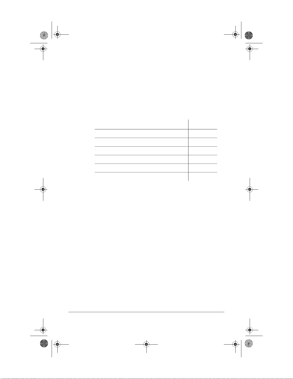
Chapter 1 describes features and functions of the Solar
Charge Controller.
For information on: See:
“Features” page 1–2
“Maximum Power Point Tracking” page 1–3
“Charge Controlling” page 1–5
“Auxiliary Output Functions” page 1–10
“Automatic PV Array Night Disconnect” page 1–12
1–1
Page 18
SolarSurveyor_RevA.book Page 2 Friday, December 1, 2006 4:32 PM
Features
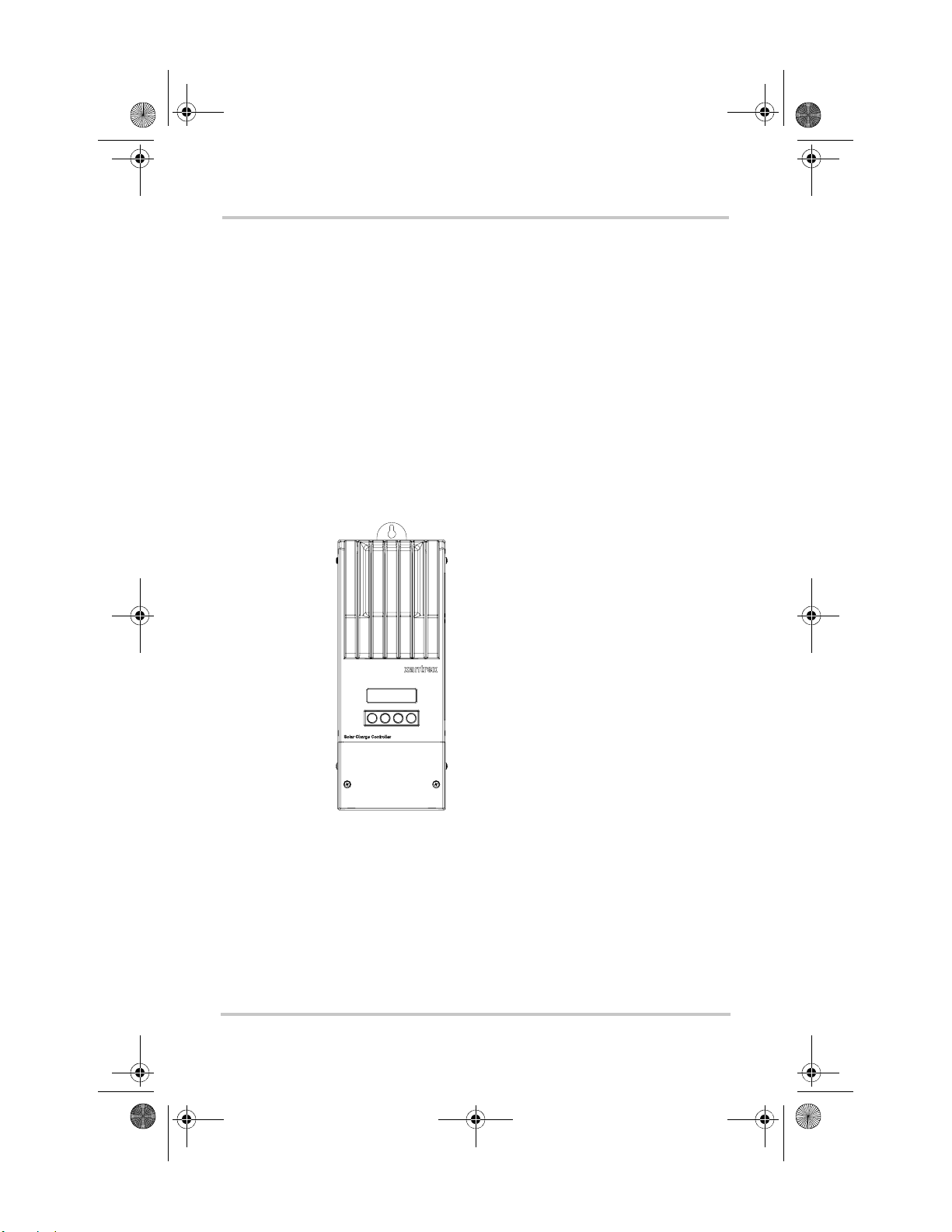
The Xantrex Solar Charge Controller is a photovoltaic (PV)
charge controller that tracks the electrical maximum power
point of a PV array to de li ver the maximum available current
for charging batteries. The Charge Controller can be used
with 12-, 24-, 36-, 48-, and 60-volt DC battery systems.
The Solar Charge Controller is designed to reg ula te PV input
only. It is not designed to work with wind or hydro
generators.
The Charge Controller can be installed (in single or multi-
unit configurations) with a Xantrex XW Series Inverter
Charger or in a stand-alone installation.
Figure 1-1
Standard features of the Solar Charge Controller include:
• Two- or three-stage charging process, with manual
equalization to maximize system performance and
maintain expected batt ery life.
1–2 975-0283-01-01 Rev A5 DRAFT
Charge Controller
Page 19
SolarSurveyor_RevA.book Page 3 Friday, December 1, 2006 4:32 PM
• Maximum Power Point Tracking (MPPT) to deliver the
maximum available power from a PV array to a bank of
batteries. See “Maximum Power Point Tracking” on
page 1–3.
• Configurable auxiliary output. See “Auxiliary Output
Functions” on page 1–10.
• Two-line, 16-character liquid crystal display (LCD) and
four buttons for configuration and system monitoring.
• Input over-voltage and under-voltage protection, output
over-current protection, and backfeed (reverse current)
protection. Warning and Fault messages appear on the
LCD when the unit shuts down as a protective measure.
• Over-temperature protection and power derating when
output power and ambient temperature are high.
• Battery Temperature Sensor (BTS) to provide
automatically temperature-compensated battery
charging.
• Xanbus
®
-enabled. Xanbus is a network communications
protocol developed by Xantre x. The Charge Controller is
able to communicate its settings and activity to other
Xanbus-enabled devices, such as the XW Series Inverter/
Charger, the System Control Panel II (SCP), XW
Automatic Generator Start (XW-AGS), and other
Xantrex XW-MPPT-60-150 Solar Charge Controllers.
• 5-year limited warranty.
Maximum Power Point Tracking
Maximum Power Point Tracking
Maximum Pow er Point Tracking allows the Charge
Controller to harve st th e maximum en er gy avail able from th e
PV array and deliver it to the batterie s.
The MPPT algorithm continuously adjusts the operating
points in an attempt to fi nd the maximum power point of the
array. The algorithm can then determine if it is har vesting
more or less power than the previous operating points.
975-0283-01-01 Rev A5 DRAFT 1–3
Page 20
SolarSurveyor_RevA.book Page 4 Friday, December 1, 2006 4:32 PM
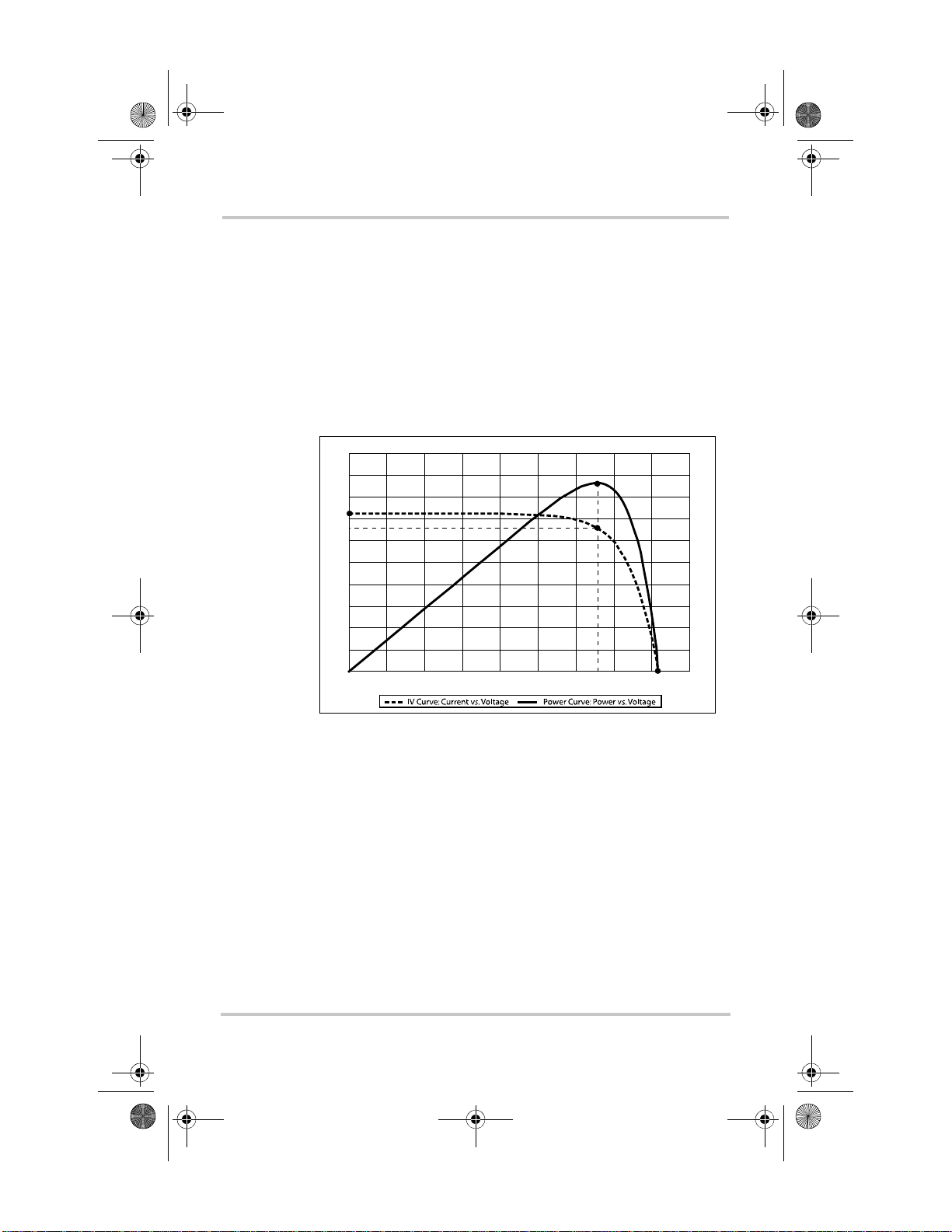
The Charge Controller applies a variable load on the array—
shown by the power curve (solid line) in Figure 1-2—until it
finds the maximum wattage (the greates t number of amps per
volt), as indicated by “MPP” in Figure 1-2. The Charge
Controlle r then holds the array at this point for as long as the
array continues to produce the required current. As panel
shading, cloud cover, and sunlight angle shift, the Charge
Controller finds the new maximum power point without
interrupting its output power flow.
20
18
16
I
sc
14
I
mp
12
10
8
6
4
Current (I) Amps / Power (P) Watts
2
0
0102030405060708090
Vol t ag e (V) Vo l t s
MPP
V
mp
V
oc
Figure 1-2
Maximum Powe r Point Curve
1–4 975-0283-01-01 Rev A5 DRAFT
Page 21
SolarSurveyor_RevA.book Page 5 Friday, December 1, 2006 4:32 PM
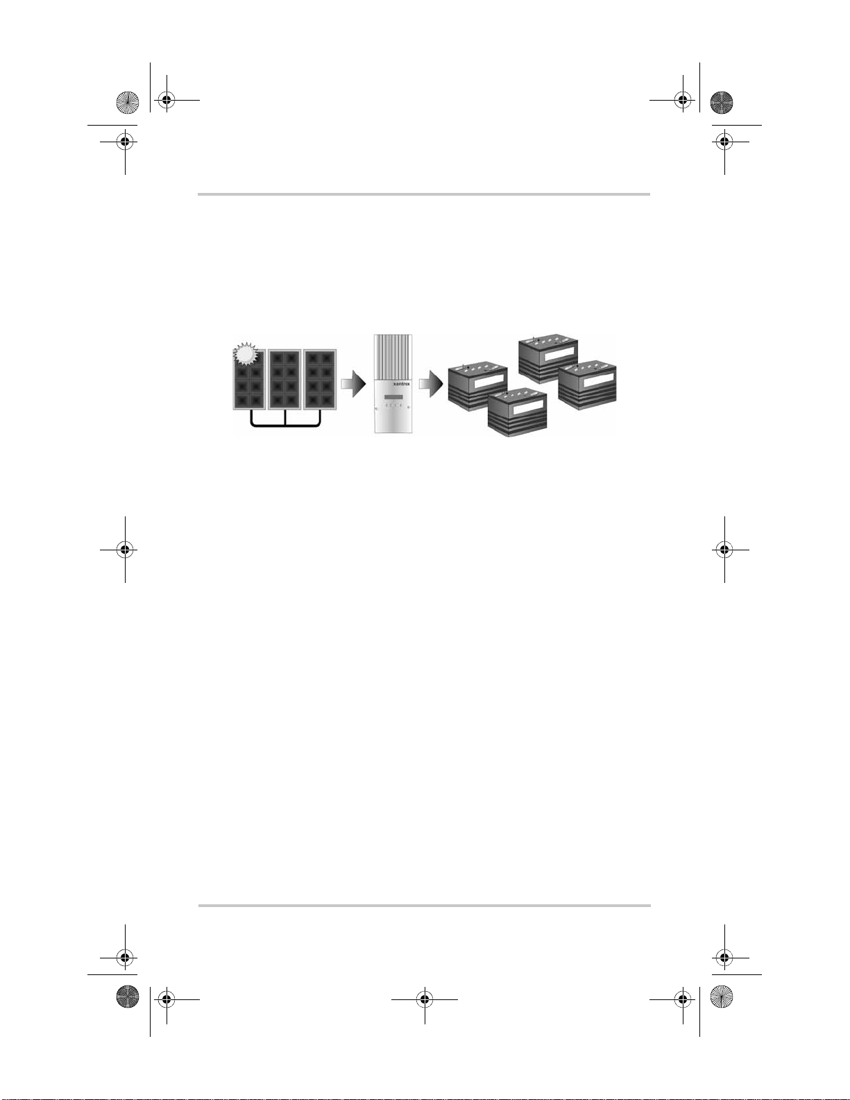
Charge Controlling
The Charge Controller can regulate PV array current at 12,
24, 36, 48 or 60 volts DC for charging batteries. It produces
up to 3500 watts and 60 amps of charging current for all
battery voltages except 60 V.
Charge Controlling
Figure 1-3
PV Charge Controller
The Charge Cont ro ll er controls how the batteries ar e charged
by the DC source (the PV arr ay). It ca n be config ured to use a
two-stage (“No Float”) or three-stage charging process to
maintain battery voltage at bulk or flo at levels.
When charging, the Charge Controller regulates the battery
voltage and the output current based on the amount of DC
power available from the PV array and the state of charge of
the battery.
The Charge Controller is able to charge a lower nominalvoltage battery from a higher-nominal voltage array. For
example, the Charge Controller can charge a 12-volt battery
from a 36-volt array. This gives flexibility to installers to use
longer wiring runs without compromising efficiency on a
higher-voltage array.
The Charge Controller is not able to charge a higher-voltage
battery from a lower-voltage array.
975-0283-01-01 Rev A5 DRAFT 1–5
Page 22

SolarSurveyor_RevA.book Page 6 Friday, December 1, 2006 4:32 PM
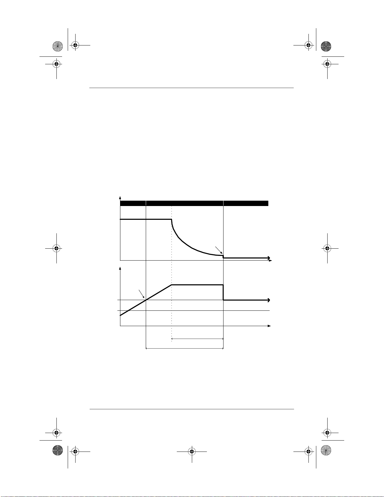
Three-Stage Battery Charging
The three-stage charging process results in more efficient
charging compared to on-off relay type or constant voltage
solid-state regulators. The final float stage reduces battery
gassing, minimizes electrolyte loss, and en sures complete
battery recharging. Battery voltage and current vary during
the three-stage charging process as shown in Figure 1-4 on
page 1–7.
Bulk Stage
During the bulk stage, the Charge Controller sets its voltage
limit to the bulk/absorption voltage setting. If the batteries are
discharged, the Charge Controller operates in constant
current mode, delivering its maximum current to the
batteries. When the battery voltage reaches the Float voltage
setting, the controller will transit ion to the absorption stage.
Absorption Stage
During the absorption stage, the Charge Controller continues
to deliver its maximum available current output until the
battery voltage reaches the bulk/absorption voltage setting.
The Charge Controller then operates in constant voltage
mode, holding the battery voltage at the bulk/absorption
voltage setting for a pre-set time limit (the default time limit
is four hours). During this time, current falls gradually as the
battery capacity i s reached . The Char ge Cont roller transition s
to the float s tage if any one of three criteria are met:
1. The charge current allowed by the batteries falls below
the exit current threshold, which is equal to 2% of battery
capacity (for a 500 Ah batt ery ban k, this wou ld be 10 A),
for one minute.
2. The battery voltage has been a t or a bove th e floa t volt ag e
(which it reached during the bulk stage) for eight hours.
1–6 975-0283-01-01 Rev A5 DRAFT
Page 23
SolarSurveyor_RevA.book Page 7 Friday, December 1, 2006 4:32 PM
3. The battery voltage has been at the bulk/absorption
voltage setting for a pre-set time limit (the Absorb CV
Time).
Float Stage
During the float stage , the volta ge of the bat tery is held at the
float voltage setti ng. Full curr ent can be provi ded to the loa ds
connected to the battery during the float stage from the PV
array. When battery voltage drops below the Exit to Bulk
Voltage threshold for 1 minute, a new bulk cycle will be
triggered.
Charge Controlling
Current
Volt age
Figure 1-4
Bulk St age
Max Current Limit
Float voltage
Absorption—
constant current
Absorption Stage
Absorption—
constant voltage
Ex i t Cu r r en t T h r e s h o l d
Bulk/Absor ption Voltage
Absorb CV Time—4 hours
(adjustable 2–6 hours)
Maximum 8 hours (f ix ed)
Three-stage Battery Charging Process
Float Stage
Float Voltage Thres hold
Exit to Bulk Vo ltage Thre shold
a
a.An actual char ging cycle f or a PV-based system that is in use while it is being charged wil l
likely differ from the cycle represented in Figure 1-4. This is because a PV system’s output
is limited by th e amount of solar energy availab le, an d also because DC loads will af fect th e
charge current and the measured battery voltage.
Time
Time
975-0283-01-01 Rev A5 DRAFT 1–7
Page 24
SolarSurveyor_RevA.book Page 8 Friday, December 1, 2006 4:32 PM
Two-Stage Battery Charging
The two-stage charging process includes the bulk and
absorption stages, but uses a “No Float” stage instead of
“Float.” Two-stage charging is recommended for off-grid
applications, where batteries are used more frequently and
maintaining them at the float voltage is both less important
and less practical. Two-stage charging can extend the life of
most batteries.
No Float Stage
During the No Float stage the Charge Controller does not
produce any charge current. Instead the Charge Controller
monitors the battery voltage and transitions back to the bulk
stage once the voltage drops below the Exit To Bulk Voltage
setting for 1 minute.
Note: For more information about battery charg ing settings, see
Table 3-2, “Battery Menu Values” on page 3–7 and Table 3-3,
“Custom Battery Menu Values” on page 3–10.
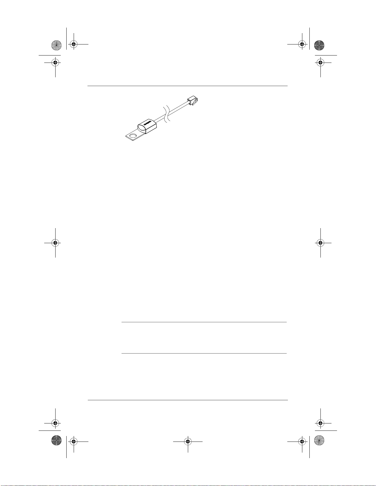
Battery Temperature Compensation
The Battery T emperature Sensor (BTS) automatically adjusts
the charging process of the Charge Controller. With the BTS
installed, the Charge Controller will increase or decrease the
battery char gi ng v olt age depending on the temperature of the
battery to optimize the charge to the battery and to protect it
from over-charge or damage. Using the BTS can extend
battery life and improve overall charging.
The BTS plugs into the BTS jack located inside the wiring
compartment of the Charge Controller. The BTS can be
installed on the negative battery post or on the side of the
battery.
1–8 975-0283-01-01 Rev A5 DRAFT
Page 25
SolarSurveyor_RevA.book Page 9 Friday, December 1, 2006 4:32 PM
Charge Controlling
Figure 1-5
Battery Tem perature Sensor
If the BTS is not installed, the voltage settings for charging
are based on one of three temperature settings (Cold, Warm,
or Hot) available on the Charge Controller configuration
menu. See “Configuring Battery Characteristics and Battery
Charging” on page 3–5.
Equalization Charging
The Charge Controller can be used to provide the battery
bank with an equalize charge.
Equalization is a deliberate overcharge designed to return
each battery cell to optimum condition by reducing sulfation
and stratification in th e battery. The equalization charge is
generally performed only on flooded, vented (non-sealed or
“wet”) lead-acid batteries, as recommended by the battery
manufacturer.
T o avoid damagi ng your batte ries, be sur e to read all cau tions
and warnings concerning equalization charging. For more
information, see “Battery Equalization” on page 4–17.
Important:
limited to 72 V for a 60 V battery system, which is the bulk
voltage setting for 60 V batteries. Because of this output limit, the
Charge Controller does not equalize 60 V batteries.
The Charge Controller maximum ou tput volta ge is
975-0283-01-01 Rev A5 DRAFT 1–9
Page 26
SolarSurveyor_RevA.book Page 10 Friday, December 1, 2006 4:32 PM
Auxiliary Output Functions
The Charge Controller has a configurable auxiliary output
(producing 5 to 13 volts at 200 mA) to drive a relay for load
control or to turn on devices such as vent fans or indicator
alarms. The auxiliary output can be configured to perform
only one function at a time.
See “Configuring the Auxiliary Output” on page 3–14 for
information about auxili ary output trigge r sources and how to
enable and configure the auxiliary output for your
application.
CAUTION
The auxiliary output is intended only to energize a low-current
circuit such as a relay coil. Connection to a high-amperage device
will open the fuse in the common line and possibly damage the unit.
Load Control
The Charge Controller auxiliary output can be configured to
drive a relay to disconnect or reconnect loads depending on
battery voltage. This load control function enables the Charge
Controller to help preve nt damage to the battery from overdischarge during periods of poor charging (due to ambient
temperature, for example) or excessive loads.
To use the Charge Controller to control loads and protect
your batteries, you must connect the Charge Controller
auxiliary output to a relay that controls a battery disconnect
to disconnect the load from the batteries. The Charge
Controller auxiliary output must be configured to activate
when the batteries reach a pre-set voltage level.
1–10 975-0283-01-01 Rev A5 DRAFT
Page 27
SolarSurveyor_RevA.book Page 11 Friday, December 1, 2006 4:32 PM
Auxiliary Output Functions
xantrex
BAT
BAT
PV+PV
+
–
–
-
+
+
-
Relay (200 mA)
LEGE N D
Ground
-
+
-
+
DC Positive
DC Negative
Figure 1-6
Load Control Wiring
975-0283-01-01 Rev A5 DRAFT 1–11
Page 28
SolarSurveyor_RevA.book Page 12 Friday, December 1, 2006 4:32 PM
Vent Fan
The Charge Controller auxiliary output can be configured to
power a small DC fan to clear a battery compartment of
harmful gases. The Charge Controller auxiliary output must
be configured to activate when the batteries reach their
gassing voltage.
The auxiliary output can also power a small DC fan to cool
the Charge Controller heat sink when the heat sink
temperature rises above a pre-set temperature.
Alarms
The auxiliary output can be configured to trigger an alarm or
indicator light when a pre-set condition occurs, such as low
or high battery voltage, high PV array voltage, or a Charge
Controller fault.
Automatic PV Array Night Disconnect
At night, or when the PV array volta ge is les s than the bat tery
voltage, the Charge Contro ller opens an internal rel ay to
prevent battery current from flowing back to the PV array. In
this mode of operation the Charge Controller draws minimal
power from the battery.
This automatic night-time disconnect eliminates the need for
a blocking diode between the battery and the PV array. If the
PV array consists of thin-film or amorphous solar modules,
diodes may still be required to prevent damage during times
of partial shading of the array. Check the documentation
provided with the PV modules.
1–12 975-0283-01-01 Rev A5 DRAFT
Page 29
SolarSurveyor_RevA.book Page 1 Friday, December 1, 2006 4:32 PM
2
Installation
Chapter 2 contains information and procedures to install
the Solar Charge Controller.
For information on: See:
“PV Array Requirements” page 2–2
“Mounting” page 2–4
“Grounding” page 2–9
“Wiring” page 2–10
“Installing the Battery Temperature Sensor” page 2–27
“Commissioning” page 2–29
2–1
Page 30
SolarSurveyor_RevA.book Page 2 Friday, December 1, 2006 4:32 PM
PV Array Requirements
Note: The following information provides only general
guidelines. The installation and rated performance of your PV
array is subject to inspection and approval by the authority having
jurisdiction.
Array Size
For PV array sizing guidelines, use the XW Solar Charge
Controller PV array sizing tool accessible from
www.xantrex.com/support.
Although the Solar Charge Controller can harvest a
maximum of 3500 W, the PV array size can be as high as
6720 W (based on 48 A × 140 Vdc = 6720 W).
Array Voltage
CAUTION: Eq uipment damage
The PV array voltage must never exceed 150 Voc (open circuit
voltage) un der any conditions.
The maximum V
MPPT operation) is 140 Vdc. The difference between V
and V
When calculating PV array size for the Solar Charge
Controller you should consider the expected V
under all possible conditions. Panel voltage increases with
decreasing temperature. The array needs to be sized so that
the 150 Vdc does not occ ur , even at the lowest expect ed panel
temperature during open circuit. The panel manufacturer
provides a V
(77
°F). Ensure that the V
temperature does not exceed 150 Vdc. A factor of 1.25 is
applied to the rated V
-21 °C.
(PV array voltage for Charge Controller
mpp
is shown in Figure 1-2 on page 1–4.
oc
rating per pa nel, b ut it is us ually rat ed at 25°C
oc
rating at the coldest ambient
oc
at 25 °C when the panel is colder than
oc
of the array
oc
mpp
2–2 975-0283-01-01 Rev A5 DRAFT
Page 31

SolarSurveyor_RevA.book Page 3 Friday, December 1, 2006 4:32 PM
Array Current
PV Array Requirements
Important:
must not exceed the 60 A input current rating of the Charge
Controller at any time.
The Isc (short circuit current) rating of the array
Panels rated up to 48 A at 25 °C (77 °F) are recommended to
allow for increases in I
solar noon. Ensure t hat the I
not exceed 60 A. A fact or of 1.25 is applied to the rated I
at low panel temperatures and at
sc
rating under all c onditions doe s
sc
at
sc
25 °C when the panel is col der than -21 ° C.
MPPT Voltage Range
The Charge Controller maximum power point tracking
algorithm maximizes the output energy of PV arrays as long
as the operating voltage is within the MPPT operational
window . Ensur e that th e PV array used i n the syst em operate s
within the MPPT operational window.
Effects of array voltages outside of the MPPT operational
window are shown in Table 2-1.
Table 2-1
Voltage Effect of Array Voltage Charge Controller Mode
MPPT Operational Window
< Batt
V
oc
(system battery voltage)
= Batt
V
MPP
V
MPP
(or V
oc
975-0283-01-01 Rev A5 DRAFT 2–3
nom
nom
> 140 Vdc
> 140 Vdc)
Charge Controller not
operating.
to 140 Vdc Maximum harvest of
solar energy.
Charge Controll er shuts
down. Unit may be
damaged if V
> 150 V.
oc
Low Light
Charging
(MPPT window)
Over-voltage fault.
Page 32

SolarSurveyor_RevA.book Page 4 Friday, December 1, 2006 4:32 PM
Mounting
The instructions in this chapter are applicable to the typical
stand-alone installation. Installation procedures will vary
according to your specific application. For special
applications, consult a qualified electrician or your Xantrex
Certified Dealer.
If installing the Charge Controller as part of an XW System,
see the XW System Installation Guide for additional
information.
Important:
electrical codes. Installation of this equipment should only b e
performed by a qualified electrician or by a Certified Renewable
Energy (RE) System installer.
Installations must be compliant with all local
Choosing a Location
The Charge Controller must be mounted vertically and
installed indoors in a dry, protected location away from
flammable materials, sources of high temperature, moisture,
and vibration. The locatio n must also be shelt ered from d irect
sunlight, rain, snow, and wind-blown debris.
CAUTION: Eq uipment damage
Never install the Charge Controller where it is exposed to salt water
spray. Exposure to salt water will void the warranty and may cause
a shock hazard.
WARNING: Explosion/corrosion hazard
To reduce the risk of fire or explosion, do not install the Charge
Controller in sealed compartments containing batteries or in
locations that require ignition-protected equipment.
To reduce the risk of corrosion from hydrogen-sulfide gas vented
by batteries, do not install the Charge Controller in sealed
compartments containing batteries.
2–4 975-0283-01-01 Rev A5 DRAFT
Page 33

150 mm (6 inches) on top and side(s)
SolarSurveyor_RevA.book Page 5 Friday, December 1, 2006 4:32 PM
If using “sealed” batteries, the controller can be mounted in
the same enclosure as long as it is adequately ventilated.
For optimal and safe operation, ensure there is adequate
clearance around the Charge Controller. See Table 2-2 and
Figure 2-1. If clea rances are reduced below these minimums,
rated performance may not be achieved.
Mounting
Table 2-2
Location Minimum Clearance
Above 150 mm (6 inches). W hen units are mo unted in a v ertical stack, the
In front Sufficient room to allow for easy access to read the display, to
On sides 150 mm (6 inches) on at least one side of the overall assembly. A
Minimum Clearance Requirements
topmost unit must maintain the minimum clearance to the nearest
surface.
prevent accidental contact with the heat sink, and to perform
maintenance.
maximum of two u
against an XW Series Power Distribution Panel (part num ber 865-
1015). In both configurations, the minimum clearance around the
outermost unit must be maintained .
nits can be mounted side by side or side mounted
975-0283-01-01 Rev A5 DRAFT 2–5
Figure 2-1
Minimum Clearance Requirements
Page 34

SolarSurveyor_RevA.book Page 6 Friday, December 1, 2006 4:32 PM
Removing the Wiri ng Terminals Cover
Before mounting, remove the wiring terminals cover to
access the mounting holes and the wiring terminals. The
wiring terminals cover is secured with two Phillips #8-32 × 2
½-inch screws on the front cover of the unit. See Figure 2-2.
Remove screws to access
the wiring terminals.
Figure 2-2
Removing the Wiring Terminals Cover
Removing Knockouts
Six dual-knockouts are provided for routing battery, PV
array, BTS, and network cables into the Charge Controller.
Bushings or conduit s mus t be used to protect the wi ri ng fr om
damage from rough edges around the knockout holes.
2–6 975-0283-01-01 Rev A5 DRAFT
Page 35

)
4)
73
.)
SolarSurveyor_RevA.book Page 7 Friday, December 1, 2006 4:32 PM
Mounting
Keyhole slot for wall mounting
(2 7/8)
280 (11)
368 (14 1/2)
Ø6.35
(1/4)
60 (2 3/8)
26.5
138
(5 7/16)
¾ and 1" dual knockouts (× 6)
(1)
14 (9/16)
(One each side, two on back, two on chassis bottom)
¾ single knockouts for BTS and network cables (× 2)
(One on back, one on chassis bottom)
Figure 2-3
Dimensions and Knockout Locations
323 (12 3/
Additional
mounting holes
53 (2 1/16
118
(4 5/8)
146
(5 3/4)
All measurements in mm (in
975-0283-01-01 Rev A5 DRAFT 2–7
Page 36

SolarSurveyor_RevA.book Page 8 Friday, December 1, 2006 4:32 PM
Mounting the Charge Controller
The Charge Controller is vertically mounted using three
#10 × ½-inch or #12 × ½-inch pan-head screws.
To mount the Charge Controller:
1. Remove the wiring terminals cover.
2. Mark the location of the keyhole slot on the wall.
3. Secure the top mounti ng screw in th e location marked.
Leave the screw head backed out approximately ¼ inch
(6 mm).
4. Place the controller onto the screw and pull it down into
the keyhole slot.
5. Insert two screws in the two mounting holes provided to
secure the unit to the wal l.
6. Provide strain-reli ef clamps or condui t to prevent damage
to the circuit board and terminal block from pulling on
the wires.
¼"
Place keyhole
slot over the
mounting screw.
Secure with two
more screws.
Figure 2-4
2–8 975-0283-01-01 Rev A5 DRAFT
Mounting the Solar Charge Controller
Page 37

SolarSurveyor_RevA.book Page 9 Friday, December 1, 2006 4:32 PM
Grounding
The Charge Controller is designed to work only with
negative-grounded el ectrical s ystems. Groundi ng for both PV
and battery circuits is provided inside the wiring
compartment. Each ground connection can accommodate up
to #6 AWG wire size.
A fuse rated at 1 A, 600 V (accessible from inside the wiring
compartment) grounds the negative conductor of the PV
array and provides PV ground-fault protection (PV-GFP).
Replace with Littelfuse KLKD 1 or equivalent.
WARNING: Shock hazard
Do not connect the battery negative to ground. NEC requirements
specify that the battery negative ground mus t be done on l y throu gh
the 1A PV-GFP fuse. Bonding the battery negati ve to ground
disables PV ground-faul t protection. The battery co mpartment must
only be grounded if it is metal. See Figure 2-7 on page 2–15 for
correct routing of the battery negative.
Grounding
This symbol iden tifies the
protective conductor
(grounding) connection.
Chassis ground terminals (2)
Figure 2-5
Charge Controller Safety Ground Connector
WARNING: Shock hazard
Disconnect PV and battery circuits before removing the grounding
connections or before removing or installing the PV-GFP fuse.
975-0283-01-01 Rev A5 DRAFT 2–9
Page 38

SolarSurveyor_RevA.book Page 10 Friday, December 1, 2006 4:32 PM
Wiring
Important:
Installations of this equipment should only be performed by a
qualified electrician or a Certified Renewable Energy (RE)
System Installer.
Installations must meet all local electrical codes.
WARNING: Shock hazard
Disconnect PV and battery circuits before wiring.
DC Terminal Connector Locations
Termin al connectors for DC wiring are located inside the
wiring compartment. The labels above the DC wiring
terminals and inside the wiring compa rtment identify all the
connection points. See Figure 2-6.
CONNECTIONS D IAGR AM
TERMINAL TORQUE RE QUI RE M E NTS
15lbf.in (1.7 Nm) FOR #14-10 AWG WIRE
18lbf.in (2.0 Nm) FOR #8 AWG WIRE
20lbf.in (2.2 Nm) FOR #6 AWG WIRE
BATTERY
BATTERY
++
--
PV PV
+
-
BTSAUX
XANBUS
XANBUS
Figure 2-6
DC Connection Terminals
Wire Size and Over-current Protection Requirements
The wiring, over-cur rent protec tion device s (fuses and ci rcuit
breakers), and installation methods used must conform to all
national and local electrical code requirements.
Wiring must be protecte d from physical damag e with conduit
or a strain relief clamp.
2–10 975-0283-01-01 Rev A5 DRAFT
Page 39

SolarSurveyor_RevA.book Page 11 Friday, December 1, 2006 4:32 PM
To preserve signal integrity on communication cables, the
BTS, auxiliary output , and ne twor k c abl es must pass through
a different conduit than the conduits used for PV wiring and
battery cables. You should pull the BTS cable through the
conduit first as the connector may not fit if other wires have
been pulled first.
Current Rating
The Charge Controller PV input is rated for 48 A continuous
(60 A maximum) I
. Since PV outputs can vary due to the
sc
array size or sunl ight a ngle, the saf e mini mum wire s ize must
be chosen for maximum array short-circuit current. Consult
PV array manufacturer specifications.
Minimum Wire Gauge
For installations where the PV array output is the maximum
allowable 60 A I
#6 AWG (13.3 mm
insulation rating. This w ire gauge is d etermined by electrical
code requirements regarding conduit knockout sizes, wire
bending radius, and space available within the Charge
Controller wiring compartment.
, the minimum allowable wire gauge is
sc
2
) copper wire with a 90 °C (194 °F)
Wiring
No crimp-on terminals or lugs are required.
Over-current Protection
Over-current protection must be installed for the battery and
PV circuits to protect the Charge Controller from short
circuits at its input and output. The NEC requires all circuits
to be protected with a device rated for 125% of the rating of
the circuit.
Battery Circuit
The DC-rated fuse or circuit breaker between the battery and
the Charge Controller must have a maximum size of 1.25 ×
60 A (the short circuit rating of the Charge Controller). That
is, the fuse or circuit breaker must be rated less than 75 A.
975-0283-01-01 Rev A5 DRAFT 2–11
Page 40

SolarSurveyor_RevA.book Page 12 Friday, December 1, 2006 4:32 PM
PV Circuit
The DC fuse or circuit breaker DC-rated fuse or circuit
breaker between the PV arra y and the Char ge Controller must
be rated for the I
of the array but cannot exceed the 60 A
sc
rating (1.25 × 48 A).
Long-distance wire runs
If there is a signi fican t dist ance be tween t he PV arr ay and t he
Charge Controller or between the Charge Controller and the
battery, larger wires can be used to reduce the voltage drop
and improve performance. Refer to Table 2-3.
WARNING: Equipment damage
Do not connect an array capable of delivering over 60 A Isc to the
Charge Controller. Wires larger than #6 AWG can be used only to
reduce power loss in the wiring.
To use a larger size wire, use a splicer block (terminal block)
approved and rated fo r this appl ication. This al lows th e larg er
cable size from the batteries to be “spliced” to the #6 AWG
wire connected to the Charge Controller. The splicer block
must be installed outside of the Charge Controller wiring
compartment.
Follow manufacturer’s recommendations for torque and
mounting. Splicer blocks and split-bolt kerneys are available
from renewable energy suppliers.
Maximum One-way Distance and Wire Size
Important:
followed for determining additional installation requirements.
Larger wire sizes may be used to improve performance, but may
not be installed directly into this Charge Controller. Use a splicer
block as previously described.
2–12 975-0283-01-01 Rev A5 DRAFT
Local and national electrical codes must be
Page 41

SolarSurveyor_RevA.book Page 13 Friday, December 1, 2006 4:32 PM
Refer to Table 2-3 and find the maximum current in the left
column, and the one-way distance from the PV array to the
Charge Contro ller (or the distance from the Charge
Controller to the battery) on the same line, then read the wire
size required at the top of the column.
Wiring
Table 2-3
One-Way Wire Distance and Wire Size
Maximum one-way wire distance for a < 3% voltage drop assuming 60 Adc
charging current
12 Vdc application shown
For 24 Vdc systems, multiply distance by 2
For 36 Vdc systems, multiply distance by 3
For 48 Vdc systems, multiply distance by 4
For 60 Vdc systems, multiply distance by 5
(34.29)
a
141.7
(43.19)
(36.00)
(30.85)
Distance in feet (meters) Distance in feet (meters)
Amps 12 AWG 10 AWG 8 AWG 6 AWG 4 AWG 3 AWG 2 AWG 1 AWG 1/0 AWG
8.8 (2.68) 14 (4.27) 22.2 (6.77) 35.3 (10.76) 56.1 (17.10) 70.9 (21.61) 89.6 (27.31) 112.5
10
7.3 (2.23) 11.6 (3.54) 18.5 (5.64) 29.4 (8.96) 46.7 (14.23) 59.1 (18.01) 74.6 (22.74) 93.7 (28.56) 118.1
12
6.3 (1.92) 10 (3.05) 15.9 (4.85) 25.2 (7.68) 40.1 (12.22) 50.6 (15.42) 64.0 (19.51) 80.4 (24.51) 101.2
14
5.5 (1.68) 8.7 (2.65) 13.9 (4.24) 22.1 (6.74) 35.0 (10.67) 44.3 (13.50) 56.0 (17.07) 70.3 (21.43) 88.6 (27.01)
16
4.9 (1.49) 8.8 (2.38) 12.4 (3.78) 19.6 (5.97) 31.2 (9.51) 39.4 (12.01) 49.8 (15.18) 62.5 (19.05) 78.7 (23.99)
18
4.4 (1.34) 7 (2.13) 11.1 (3.38) 17.6 (5.36) 28.0 (8.53) 35.4 (10.79) 44.8 (13.66) 56.2 (17.13) 70.9 (21.6)
20
25
30
35
40
45
50
60
5.6 (1.71) 8.9 (2.71) 14.1 (4.30) 22.4 (6.83) 28.3 (8.63) 35.8 (10.91) 45.0 (13.72) 56.7 (17.28)
4.7 (1.43) 7.4 (2.26) 11.8 (3.60) 18.7 (5.70) 23.6 (7.19) 29.9 (9.11) 37.5 (11.43) 47.2 (14.39)
6.4 (1.95) 10.1 (3.08) 16.0 (4.88) 20.2 (6.16) 25.6 (7.80) 32.1 9.78) 40.5 (12.34)
5.6 (1.71) 8.8 (2.68) 14.0 (4.27) 17.7 (5.39) 22.4 (6.83) 28.1 (8.56) 35.4 (10.79)
7.8 (2.38) 12.5 (3.81) 15.7 (4.79) 19.9 (6.07) 25.0 (7.62) 31.5 (9.60)
7.1 (2.16) 11.2 (3.41) 14.2 (4.33) 17.9 (5.46) 22.5 (6.86) 28.3 (8.63)
6.3 (1.92) 9.3 (2.83) 11.8 (3.60) 14.9 (4.54) 18.7 (5.7) 23.6 (7.19)
a.These wire sizes a re not approved to be instal led in the controller, but may be used
external to the controller (using a splicer block) to reduce voltage drop and improve
performance.
975-0283-01-01 Rev A5 DRAFT 2–13
Page 42

SolarSurveyor_RevA.book Page 14 Friday, December 1, 2006 4:32 PM
Connecting the Charge Controller
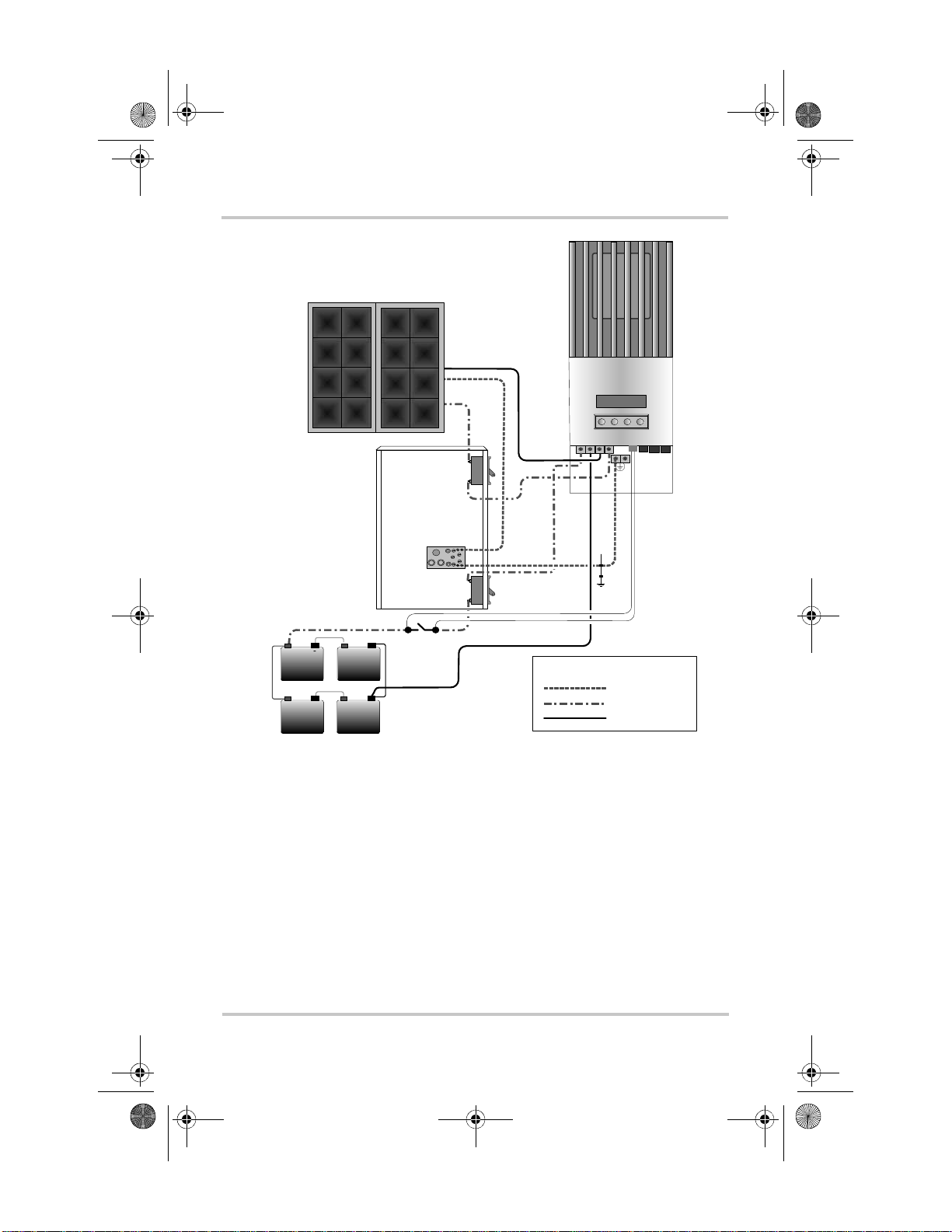
The following procedure is illustrated in Figure 2-7.
WARNING: Shock hazard
Whenever a PV array is exposed to light, a shock hazard exists at
the output wires or exposed terminals. To reduce the risk of shock
during installation, cover the array with an opaque (dark) material
before making the connections.
WARNING: Shock hazard
Do not connect the battery negative to ground. Bonding the battery
negative to ground di sab les P V gro und-fault protection. See Figure
2-7 on page 2–15 for correct routing of the battery negative.
To connect the Charge Controller:
1. Connect the PV array’s positive (+) output to the PV
array disconnect.
2. Route another (+) cable from the other end of the PV
disconnect to the Charge Controller terminal marked
PV +.
3. Connect the PV array’s negative (–) output to the Charge
Controller terminal marked
PV –.
4. Connect a positive (+) cable from the Charge Controller
terminal ma rked
BAT + to the battery disconnect.
5. Connect a second positive (+) cable to the other side of
the battery disconnect and connect to the positive (+)
battery terminal.
CAUTION: Reverse polarity damage
Before making the final DC connection or closing the DC breaker
or disconnect, check cable polarity at both the battery and the
Charge Controller. Positive (+) must be connected to positive (+).
Negative (–) must be connected to negative (–).
6. Connect the negativ e (–) battery cable to the Charge
Controller terminal marked
2–14 975-0283-01-01 Rev A5 DRAFT
BAT –.
Page 43

SolarSurveyor_RevA.book Page 15 Friday, December 1, 2006 4:32 PM
7. Torque the Charge Controller terminals according to the
following table:
Wire Size Torque Value
2
AWG mm
in-lb Nm
14–10 2.5–6 15 1.7
8 10182
6 16202.25
Allow some slack on the cables within the Charge
Controller and secure the wiring with strain reliefs or
cable clamps.
Wiring
DC
disconnect
Ground metal battery
enclosure to unit.
-
+
-
+
Figure 2-7
Charge Controller Wiring
–
xantrex
+
BAT
PV+PV
BAT
+
–
–
PV array
disconnect
Primary
system
Battery
disconnect
-
+
ground
LEGE N D
Ground
-
+
Do not connect the battery
negative to ground.
DC Positive
DC Negati v e
975-0283-01-01 Rev A5 DRAFT 2–15
Page 44

SolarSurveyor_RevA.book Page 16 Friday, December 1, 2006 4:32 PM
Connecting Multiple Units
Each Charge Controller must be conn ected to a se parate PV
array. The PV arrays mus t be of the sam e type with si milar
fill factor and maximum power point voltage.
WARNING: Shock hazard and equipment
failure
Ensure each Charge Controller is correctly con nected to its own PV
array(s) and that no wires are crossed. If Charge Controllers “share”
more than one PV array, an input current difference of over 1 A
between arrays can cause each Charge Controller to fail—the
ground fault protection fuse will blow, followed by short circuit
failure. See Figure 2-8.
xantrex
BAT
PV+PV
BAT
+
–
–
Figure 2-8
xantrex
BAT
PV+PV
BAT
–
+
–
Improper Multiple Charge Controller DC Wiring
2–16 975-0283-01-01 Rev A5 DRAFT
Page 45

SolarSurveyor_RevA.book Page 17 Friday, December 1, 2006 4:32 PM
Aux Output Connections
WARNING
If the PV-GF P internal protection has activated, shock-hazardous
voltages may appear at the AUX connector. To avoid a shock
hazard, ensure that all connections made to the AUX terminals have
no uninsulated wire segments and that all wiring has an insulation
rating of at least 300 V.
The auxiliary output connectors can accept 22 AWG to 14
AWG copper solid or stranded wire.
Network Installation
The Xantrex XW-MPPT-60-150 is a Xanbus®-enabled
device. Xanbus is a network communications protocol
developed by Xantrex. The Charge Controller is able to
communicate its settings and activity to other Xanbusenabled devices, s uch as the XW Series Inverter/Charger, the
System Control Panel II (SCP), XW Automatic Generator
Start (XW-AGS), and other Xantrex XW Solar Charge
Controllers.
Aux Output Connections
Communications wiring (using Xanbus network cables)
between mu ltiple Charge Controllers al lows information
about each Charge Controller and its associated PV array to
be communicated between all of the Charge Controllers in
the system. Information about the entire system can be
displayed on any Charge Controller LCD in the system.
For example, in a two-Charge Controller system, if Charge
Controller #1 is pr oduc ing 1500 W and Charge Control le r # 2
is producing 2000 W, both units display a t otal system power
of 3500 W. The accumulated amp-hours and kilowatt-hours
produced by both units that day is also displayed.
Without communica tions wiring , each Charge Controller in a
system will only display information specific to the unit and
its associated PV array.
975-0283-01-01 Rev A5 DRAFT 2–17
Page 46

SolarSurveyor_RevA.book Page 18 Friday, December 1, 2006 4:32 PM
Network Components
A Xanbus network consists of the following components:
• Xanbus-enabled devices—these include the Charge
Controller, the XW Seri es Inverter/C harger, XW-AGS,
and SCP II. The network can consist of a maximum
number of 20 devices, with no more than 10 of one kind
of device.
• Xanbus power supply—the network requires a power
supply capable of providing 15 Vdc/200 mA to each
device. The XW Series Inverter/Charger can provide
network power, but if no inverter/charger is installed, an
external power supply is required. Contact Xantre x for
more information.
• Network cables—each Xanbus-enabled device is
connected by a Category 5 (CAT 5 or CAT 5e) cable, a
standard cable available from Xantrex or any computer
supply store. The cable consists of eight conductors in
four twisted p air s wit h an RJ45 modular connector wir ed
to the T568A standard.
CAUTION: Eq uipment damage
Do not use crossover cable.
T abl e 2-9 contain s the arr angeme nts of wir e colors to pin
numbers for the T568A standard.
2–18 975-0283-01-01 Rev A5 DRAFT
Page 47

SolarSurveyor_RevA.book Page 19 Friday, December 1, 2006 4:32 PM
Network Installation
Figure 2-9
Pin Number
T568A Standard Wiring
Conductor
Name
1 NET_S White/Green White/Orange
2 NET_S Green Orange
3 NET_C White/Orange White/Green
4 CAN_L Blue Blue
5 CAN_H White/Blue White/Blue
6 NET_C Orange Green
7 NET_S White/Brown White/Brown
8 NET_C Brown Brown
Figure 2-10
CAT 5 Cable
Insulation Color
Pins: 8 7 6 5 4 3 2 1
RJ45 Connector
CT5E Cable
Insulation Color
• Network terminators (Figure 2-1 1)—the Xan bus network
must be properly terminated at each end with male or
female network terminators to ensure the communication
signal quality on the network. If the network is not
properly terminated, signal quality is degraded and
performance on the network is reduced. Permanent
configuration with no terminators is not supported by
Xantrex. The Charge Controller ships with one male
terminator already i nst al led. Depending on your network
layout, this terminator may need to be removed and
inserted into another device elsewhere in the network.
975-0283-01-01 Rev A5 DRAFT 2–19
Page 48

SolarSurveyor_RevA.book Page 20 Friday, December 1, 2006 4:32 PM
Male network terminator
Figure 2-11
Network Terminators
Female network
terminator
• Network connectors—The three -way conn ect or houses
three RJ45 jacks that provide a device connection point
on a multi-drop backbone layout (see “Multi-Drop
Backbone Layout” on page 2–22). All three jacks are
wired identically and can accept either network c abl es o r
terminators. One jack is available for connecting to a
Xanbus-enabled device. The remaining jacks are
reserved for connection to other network connectors, a
network cable terminated with a female terminator, or a
male termin ator.
The network connector is mounted to a bulkhead or a
wall, as shown in Figure 2-12.
To network
connector or teminator
Figure 2-12
2–20 975-0283-01-01 Rev A5 DRAFT
Three-Way Network Connector
To device
To network connector
Page 49

SolarSurveyor_RevA.book Page 21 Friday, December 1, 2006 4:32 PM
Ordering Network Components
Table 2-4 provides a partial list of network components and
part numbers. Pre-made cables are available in standard
lengths from 3 feet to 75 feet.
For the most up-to-date list , call you r dealer. Call your dealer
or visit the Outlet Store at www.xantrex.com to purchase
cables and other network components.
Network Installation
Table 2-4
Network Component Part Number
Network termination—Male (2 per pack) 809-0901
Network termination—Female (2 per pack) 809-0905
Three-way network connector 809-0903
Network cable 3 ft. (0.9 m) 809-0935
Network cable 5 feet (1.5 m) 809-0936
Network cable 7 feet (2.0 m) 809-0937
Network cable 10 feet (3.0 m) 809-0938
Network cable 14 feet (4.3 m) 809-0939
Network cable 25 feet (7.6 m) 809-0940
Network cable 50 feet (15.2 m) 809-0941
Network cable 75 feet (22.9 m) 809-0942
Network Layout
Xanbus-enabled devices can be connected in one of two
Xanbus System layouts: multi-drop backbone or daisy chain.
Each network layout has advantages and disadvantages,
depending on the application and/or environment. It is up to
you or your system designer to decide which layout is best
for your installation .
Network Components and Part Numbers
Important:
Mixed configurations are not supported by Xantrex.
975-0283-01-01 Rev A5 DRAFT 2–21
Do not mix the two types of network layouts.
Page 50

SolarSurveyor_RevA.book Page 22 Friday, December 1, 2006 4:32 PM
Multi-Drop Backbone Layout
In a multi-drop backbone layout, each Xanbus-enabled
device on the network is connected by a drop cable to the
network bus or backbone with a network connect or , as shown
in Figure 2-13.
Network terminators are required at both ends of the multidrop backbone cable, as sho wn in Figure 2-13 . Therefore , the
Xanbus-enabled devices do not require their own
termination.
If cables are placed at the end of the network, female
terminators are required. Otherwise, male terminators can be
inserted directly into the open j ack of each n etwork connecto r
at the end of the network. See Figure 2-13.
Advantages The multi-drop backbone layout gives extra
reliability and robustness.
In this layout, Xanbus-enabled devices can be removed or
replaced while still keeping the network operating.
Disadvantage The main disadvantage of this layout is cost.
The network connectors are more expensive than in a daisy
chain layout (which uses no network connectors), and each
device in this layout requires its own network connector.
2–22 975-0283-01-01 Rev A5 DRAFT
Page 51

SolarSurveyor_RevA.book Page 23 Friday, December 1, 2006 4:32 PM
Network Installation
Network terminator
(female)
Figure 2-13
Multi-Drop Backbone Layout
Daisy Chain Layout
In a daisy chain layout, each device on the network is linked
with separate lengths of cable, as shown in Figure 2-14. This
layout does not require network connectors.
As in the multi-drop backbone layout, two terminators are
required to ensure the communication signal quality on the
network. The Xanbus-enabled devices at each end of the
chain must have a male terminator inserted into their open
network ports, as shown in Figure 2-14.
Advantage The advantage of this layout is that it is less
expensive to install because network connectors are not
required.
Network can be terminated with cables and female
terminators or male terminators in connectors.
Disadvantage The disadvantage of the daisy chain layout
is that Xanbus-enabled devices cannot be removed from the
network without interrupting the network. To make the
975-0283-01-01 Rev A5 DRAFT 2–23
Page 52

SolarSurveyor_RevA.book Page 24 Friday, December 1, 2006 4:32 PM
network function after removing a device, you must connect
the Xanbus-enabled devices on either side of the missing
device to each other or replace the device.
Network terminator
(male)
Figure 2-14
Xanbus cable
Daisy Chain Layout
Network terminator
(male)
2–24 975-0283-01-01 Rev A5 DRAFT
Page 53

SolarSurveyor_RevA.book Page 25 Friday, December 1, 2006 4:32 PM
Network Installation
Guidelines for Routing the Network Cables
WARNING: Shock hazard
:
Do not route the network cables in the same conduit or panel as the
DC input/output cables.
Connecting Network Cable Between Multiple Units
CAUTION: Equipment damage
Connect only Xanbus-enabled devices.
Although the cabling and connectors used in this network system
are the same as ethernet connectors, this network is not an
ethernet system. Equipment damage may result from attempting to
connect the Charge Controller to different systems.
CAUTION: Unpredictable device behavior
Do not connect one end of the network to the other to make a ring
or loop.
The procedure assumes only two Charge Controllers are
connected. However, there can be up to ten Charge
Controllers connected in a network. The maximum network
size is limited to 20 Xanbus-enabled devices in total.
WARNING: Shock hazard
Before opening the Charge Controller wiring compartment, ensure
the PV array and batteries are disconnected. To reduce the risk of
shock, cover the array with an opaque (dark) material.
Multi-Drop Backbone Layout
To connect network cables between multiple units:
1. Remove the wiring compartment cover from each unit.
2. Install one network connector for each Charge
Controller.
975-0283-01-01 Rev A5 DRAFT 2–25
Page 54

SolarSurveyor_RevA.book Page 26 Friday, December 1, 2006 4:32 PM
3. Connect a network cable from the nearest network
connector to an RJ45 port in Charge Controller #1.
4. Repeat the previous step for each additional Charge
Controller.
5. Connect each network connec tor with a network cabl e as
shown in Figure 2-13.
6. Ensure the factory- supplied male network te rminators (or
a network cable and female terminator) are inserted into
the empty RJ45 ports in the network connectors at the
beginning and end of the network. There should be no
empty RJ45 ports in any of the network connectors.
Daisy Chain Layout
To connect network cables between multiple units:
1. Remove the wiring compartment cover from each unit.
2. Connect the network cable to an RJ45 port in Charge
Controller #1.
3. Route the cable to Charge Controller #2.
4. Connect the network cable to an RJ45 port in Charge
Controller #2.
5. For more than two Charge Controllers, continue
connecting cable as described above.
6. Ensure the factory- supplied male net work terminator s are
inserted into the empty RJ45 ports in the Charge
Controllers at the beginning and end of the network.
There should be no empty RJ45 ports in any of the
Charge Controllers.
2–26 975-0283-01-01 Rev A5 DRAFT
Page 55

SolarSurveyor_RevA.book Page 27 Friday, December 1, 2006 4:32 PM
Installing the Battery Temperature Sensor
Installing the Battery Temperature Sensor
Installing a Battery Temperature Sensor (BTS) is highly
recommended for optimum charging performance and
extending battery life . The BTS automatic ally adjus ts batt ery
charging voltage depending on the ambient temperature.
With a BTS installed, the Charge Controller can also detect
over-temperature and under-temperature battery conditions
and suspend charging until the battery temperature is
suitable.
If a BTS is no t installed and the batteries will operate in hot
or cold conditions, manually adjust the temperature settings
to suit the conditions. See “Configuring Battery
Characteristics and Battery Charging” on page 3–5.
Important:
wires are shorted, the Charge Controller displays an overtemperature fault message. If the BTS wires have been cut, the
Charge Controller assumes that the BTS is not connected.
Important:
conduit than the conduits used for PV wiring and battery cables.
If the wiring to the sensor is damaged and the
The BTS cable must pass through a different
To install the BTS:
1. Remove the Charge Controller wiring compartment
cover.
2. Connect the ring terminal on the BTS directly to a battery
terminal (recommended), or affix the double-sided
adhesive backing (i ncluded) to the sensor back and at tach
the sensor to the side of the battery to be monitored.
If using the adhesive backing, install the BTS on the sid e
of the battery below the electrolyte level. It is best to
place the sensor be twee n ba tteries and place the batter ie s
in an insulated box to re duce the inf luence of the ambient
temperature outside the battery enclosure.
3. Pass the end of the BTS cable through a conduit hole on
the Charge Controller and insert the BTS plug into the
BTS port.
975-0283-01-01 Rev A5 DRAFT 2–27
Page 56

r.
SolarSurveyor_RevA.book Page 28 Friday, December 1, 2006 4:32 PM
4. Replace the Charge Controller wiring compartment
cover.
xantrex
+
–
Figure 2-15
BAT
BAT
+
+
–
+
–
Installing the BTS
BTS
PV+PV
–
Port
–
+
–
Insert the BTS plug
into the BTS port on
the Charge Controlle
Attach the BTS to a
battery terminal or to
the side of a battery.
2–28 975-0283-01-01 Rev A5 DRAFT
Page 57

SolarSurveyor_RevA.book Page 29 Friday, December 1, 2006 4:32 PM
Commissioning
During commissioning, the Char ge Controller prompts you to
enter important system information such as the nominal
battery voltage, battery type, and battery bank capacity. If
you have not installed the system yourself, ensure you have
this system information prior to comm issioning.
Configuration Screens
When power is first a ppl ied to the Charge Controller, s eve ral
configuration screens prompt you to enter the following
information:
• A “DC out” (battery) connection, which enables the
Charge Controller to read and share the same battery
information with other Xanbus-enabled devices that
charge or invert from the same battery bank.
• Battery type: Flooded (default), Gel, AGM, Custom.
If you select Custom, the settings for battery type match
the default settings for Flooded batteries until you
reconfigure the set tings on the Cust om Battery menu. See
“Setting a Custom Battery Type” on page 3–9.
• Nominal battery voltag e of the bat tery ban k connect ed to
the Charge Controller.
The Charge Controller automatically detects battery
voltages of 12 V, 24 V and 48 V. If your nominal system
voltage is 36 V or 60 V, enter the correct system voltage
on this screen.
• Battery bank capacity, in amp-hours.
Commissioning
975-0283-01-01 Rev A5 DRAFT 2–29
Page 58

SolarSurveyor_RevA.book Page 30 Friday, December 1, 2006 4:32 PM
Battery
Bank 1
Battery Type
Flooded
Battery Volta ge
48V
Battery Capacit y
300Ah
Figure 2-16
Configuration Screens
Commissioning a Single Unit
To commission the Charge Controller:
1. Apply battery power to the unit with a disconnect or
selector switch.
The LCD displays the two star tup sc reens in se quence, as
shown in Table 2-5, followed by the configuration
screens. The startup screens are only displayed when the
power to the unit is removed and then replaced.
Table 2-5
XW-MPPT60-150
Ver 01.00
Build 0005
Startup Screens on Charge Controller Front Panel D isplay
Display Duration Description
Xantrex
5 sec. Startup message 1: Charge Controller
model number
5 sec Startup message 2: Firmware version and
build numbers. This screen is also available
in the Device Menu for referencing during
normal operation (see page 3–23).
2. At the Battery screen, select a name (such as Bank 1) for
the battery bank connected to the Charge Controller.
Selecting a name is important for multiple Charge
2–30 975-0283-01-01 Rev A5 DRAFT
Page 59

SolarSurveyor_RevA.book Page 31 Friday, December 1, 2006 4:32 PM
Controller installations (where units share data over a
network), because it a ssociates t hat battery ba nk with that
unit.
3. At the Battery Type screen, select the battery type for
your system. Confirm by pressing Enter.
4. When the Battery Voltage screen appears, check that the
Charge Controller has detected the correct syst em
voltage.
5. Press Enter to confirm the detected battery voltage, or if
the unit has not successfully detected the volta ge, select
the correct voltage using the arrow buttons. When the
correct battery voltage appears, press Enter.
6. At the Battery Cap acity scr een, select the batt ery capaci ty
of your system. Confirm by pressing Enter.
7. Uncover the PV array and/or apply power with the
disconnect or selector switch.
The Charge Controller st arts up in sleep mode and wai ts for a
short period to determ ine that the in put volt age is greate r than
the output voltage. The LCD indicates the Charge Controller
mode or any error conditions that may be present (see
“Viewing Operating Status” on page 4–2). After the input
voltage exceeds the o utput volt age by the r equ ired mar g in f or
10 seconds, the unit begins operating.
Commissioning
975-0283-01-01 Rev A5 DRAFT 2–31
Page 60

SolarSurveyor_RevA.book Page 32 Friday, December 1, 2006 4:32 PM
Commissioning Multiple Units
When commissioning an installation with several Charge
Controllers on the same network, care must be taken to set a
unique “instance” and the correct DC Out (or Battery)
connection for each unit. The connection is important to
define so that system tot als and other related information are
displayed accurately on each unit’s LCD.
Once the first unit is configured, you can copy that
configuration to all other units by following the prompts on
the LCD.
To commission multiple Charge Co ntrollers:
1. Power up the first un it.
2. At the Charger screen, set the device instance. The
default instance is 00, but it can be set to any number
between 00 and 31.
3. A “Copy Config?” screen appears.
The options are Yes/No/L eave. Select No for the fir st
unit, then you'll be prompted to enter:
• Battery association (default is Bank 1)
• Battery voltage
• Battery type
• Battery capacity.
4. Perform steps 3 through 7 as described in
“Commissioning a Single Unit”.
5. Apply power to the next unit and set its instance to a
number one higher than the previous unit.
6. A “Copy Config?” screen appears. Select Yes.
7. A “Copy From?” screen appears. Select the instance of
the first Charge Controller you configured.
The first Charge Controller’s configuration is copied to
the second unit.
Repeat steps 4 through 6 for each additional networked unit.
2–32 975-0283-01-01 Rev A5 DRAFT
Page 61

SolarSurveyor_RevA.book Page 1 Friday, December 1, 2006 4:32 PM
3
Configuration
Chapter 3 contains information and procedures to
configure the Solar Charge Controller.
For information on:
“Configuration Menus” page 3–3
“Configuring Battery Characteristics and
Battery Charging”
“Configuring Charge Controller Input” page 3–12
“Configuring the Auxiliary Output” page 3–14
“Configuring the LCD” page 3– 21
“Resetting to Factory Defaults” page 3–25
See:
page 3–5
3–1
Page 62

SolarSurveyor_RevA.book Page 2 Friday, December 1, 2006 4:32 PM
Configuring the Charge Controller
The following sect ion s describe how to configure the Charge
Controller for the desired application and function.
The Charge Cont roller is con figured usi ng the four buttons on
the front of the unit.
Table 3-1
Button Function
Enter • Displays the next screen level. For example,
Up arrow • Displays previous menu or menu item. For
Down arrow • Displays the next menu or menu item. For
Exit • Cancels selection of a menu item
Charge Controller buttons
pressing Enter from the Batte ry Menu selection
screen displays the fir s t configurable item on
the Battery menu.
• Selects and confirms selection of a menu item
example, pressing the Up arrow from the
Battery Menu selection screen displays the
History Menu selection screen.
• Increases a selected value
example, pressing the Down arrow from the
Battery Menu selection screen displays the
Input Menu selection screen.
• Decreases a selected value
• Displays the previous screen level. For
example, pressing Exit from the Equalization
Reminder screen on the Battery Menu di sp la ys
the Battery Menu selection screen. Pressing
Exit again displays the top-level operating
screens.
3–2 975-0283-01-01 Rev A5 DRAFT
Page 63

u
t
SolarSurveyor_RevA.book Page 3 Friday, December 1, 2006 4:32 PM
Configuration Menus
The Charge Controller has seven menus for setup and
monitoring system performance as shown in Figure 3-1:
Configuration Menus
FAULTS AND
WARNINGS MENU
HISTORY MENU
BATTERY MENU
INPUT MENU
AUX MENU
DISPLAY MENU
DEVICE MENU
RESET MENU
Not a configuration menu. See page 4–10.
View and reset data logs and monitor Charge
Controller performance.
Configure battery and battery charger parameters.
See page 3–5 and page 4–17.
Turn off automatic MPPT and set a reference voltage.
See page 3–12.
Set up the auxiliary output. See page 3–14.
Set up custom screens and LCD appearance, and selec
to view basic or advanced menus. See page3–21.
Change the mode of operation and view the network ID
of the Charge Controller. See page 3–23.
Reset the Charge Controller to factory defaults.
page 3–25.
See
See page 4–15.
= Adv anced men
Figure 3-1
Configuration Menu Selection Screens (Advanced Menus in
Gray)
975-0283-01-01 Rev A5 DRAFT 3–3
Page 64

SolarSurveyor_RevA.book Page 4 Friday, December 1, 2006 4:32 PM
t
l
U
N
E
M
T
E
S
E
R
U
N
E
M
E
C
I
V
E
D
U
N
E
M
Y
A
L
P
S
I
D
U
N
E
M
X
U
A
u
a
f
t
e
c
D
e
o
l
T
e
S
t
e
s
e
R
1
5
0
0
D
5
.
g
r
n
e
i
e
g
t
0
d
r
a
0
o
a
r
M
h
e
Enter Exit
C
p
O
5
8
d
l
o
H
s
c
s
t
e
t
e
h
s
s
n
g
0
a
t
i
3
r
h
l
t
g
k
n
i
c
o
r
a
C
B
B
e
e
g
c
a
r
x
t
u
u
l
o
A
o
S
V
f
l
f
r
t
a
O
e
t
u
g
a
n
g
B
a
i
M
w
r
o
T
L
0
I
3
0
0
1
0
m
3
e
7
n
t
9
o
s
8
i
d
y
4
s
l
S
5
r
i
e
u
V
B
1
2
n
e
e
r
u
c
n
S
e
M
m
o
t
s
u
C
V
V
0
0
.
.
0
2
1
1
r
e
g
r
g
a
i
e
r
l
T
C
s
n
n
e
e
r
u
c
n
S
e
M
m
o
t
s
u
C
1
1
0
0
:
:
1
1
0
0
y
y
a
a
l
l
e
e
D
D
g
r
i
r
l
C
T
e
e
d
e
o
r
M
Enter
c
c
i
S
o
y
s
N
a
a
l
l
t
B
l
p
o
r
c
S
l
e
v
e
L
V
2
t
1
u
p
t
u
O
x
s
e
i
t
D
1
n
l
1
n
r
c
S
i
H
e
e
d
v
o
i
M
t
c
A
Adva nced
menu
=
Exit
t
x
e
t
2
n
l
1
n
r
c
S
Exit
Enter
t
t
1
n
e
e
r
s
c
e
S
Y
r
a
e
l
C
2
x
x
e
e
n
t
t
e
e
1
2
r
s
n
n
c
e
l
l
S
Y
2
2
r
a
n
n
e
r
r
l
c
c
C
S
S
U
N
E
M
T
U
P
N
I
U
N
E
M
Y
R
E
T
T
A
B
U
N
E
M
Y
R
O
T
S
I
H
U
N
D
E
N
M
A
S
S
G
T
N
L
I
U
N
A
R
F
A
W
Figure 3-2
V
s
o
0
t
t
.
l
u
0
A
0
1
e
g
c
n
n
i
e
k
r
c
e
a
f
r
e
T
R
e
e
z
t
i
a
l
v
a
i
u
t
q
c
E
A
s
g
o
L
y
l
i
Enter Exit Enter Exit Enter Exit Enter Exit Enter Exit Enter Exit
a
D
u
n
s
e
t
M
l
u
g
a
n
F
i
n
e
r
v
Enter Exit
a
i
W
t
c
d
A
n
a
s
o
t
u
V
u
o
p
V
m
y
n
0
y
a
I
5
n
r
1
o
r
V
n
A
P
A
x
a
M
y
n
a
o
d
i
0
t
a
r
z
e
i
d
l
n
a
i
u
m
q
e
E
R
s
g
o
L
y
l
h
t
n
o
M
t
l
u
t
a
c
F
e
l
r
e
a
S
e
l
C
e
p
y
y
d
1
T
r
e
e
d
k
y
t
o
n
r
t
o
a
e
a
l
B
t
B
F
t
a
B
h
h
h
h
A
A
W
W
k
k
k
k
0
3
8
0
.
.
9
4
0
3
8
2
8
5
3
5
4
5
9
7
l
a
e
t
f
o
i
T
L
Exit
Ente r
t
l
o
V
r
e
d
n
U
t
t
a
B
Complete Configuration Menus (Advanced Menus in Gray)
e
e
g
a
t
l
o
V
V
0
.
e
6
z
1
i
l
a
u
q
E
Exit
Enter
e
y
g
r
a
e
t
t
l
t
o
a
u
o
V
B
n
t
e
u
y
m
M
A
r
o
e
t
t
s
t
u
a
C
B
y
r
o
t
Exit
t
Ente r
s
c
i
e
H
l
e
W
h
r
S
0
W
a
3
k
e
2
0
l
3
0
C
k
.
P
0
3
0
0
-
y
h
a
A
d
0
o
2
T
5
e
g
a
t
l
V
o
4
V
.
4
b
1
r
o
s
b
A
h
A
A
0
0
6
0
0
t
1
i
m
y
i
t
L
i
c
r
a
r
p
u
a
C
C
W
h
0
W
0
k
2
0
3
0
k
.
P
4
2
1
0
-
y
h
a
A
d
0
o
8
T
4
p
g
a
t
l
V
o
2
V
.
4
t
1
a
o
l
F
e
m
i
T
n
V
i
C
m
0
b
4
r
2
o
s
b
A
Exit
Ente r
W
h
0
W
0
k
2
0
3
0
k
5
P
1
0
0
h
-
A
h
k
t
5
n
.
o
0
M
2
C
k
m
g
l
o
e
u
C
d
B
V
/
5
r
V
o
.
o
m
T
2
s
0
1
n
.
t
e
7
i
s
2
x
T
-
E
?
p
e
t
a
t
k
S
l
u
e
B
c
r
o
F
W
h
0
W
0
k
3
0
3
5
k
2
P
1
1
0
h
-
A
h
k
t
4
n
.
o
9
M
1
p
m
m
e
e
T
T
m
C
t
r
y
0
t
a
r
3
a
W
e
B
t
t
t
a
e
B
S
m
m
h
o
t
r
i
F
r
e
o
g
p
1
g
a
u
0
l
t
t
-
A
S
e
1
S
e
3
g
y
r
p
a
o
h
C
C
3–4 975-0283-01-01 Rev A5 DRAFT
Page 65

SolarSurveyor_RevA.book Page 5 Friday, December 1, 2006 4:32 PM
Configuring Battery Characteristics and Battery Charging
Basic and Advanced Menus
Some menus and associated setup items can be viewed in
basic and advanced display modes. You can choose to view
the basic or advanced menus on the Display Menu (see
“Configuring the LCD” on page 3–21).
Basic menus contain items you may have to view and adjust
on a routine basis. Advanced menus contain items intended
for service personnel and one-time setup, such as auxiliary
output configuration and defining custom battery types.
The Input Menu, Auxiliary Menu, and Reset Menu are
advanced menus only, as are some items on the History Menu
and Battery Menu.
Configuring Battery Characteristics and
Battery Charging
On the Battery Menu you can:
• Start battery equalization
• Set battery equalization voltage
• Configure your battery type, voltage and amp-hour
capacity
• Configure a custom bat te ry type by adjusting settings for
each battery charge stage and fine-tuning temperaturecompensated charging
• Monitor battery temperature.
975-0283-01-01 Rev A5 DRAFT 3–5
Page 66

u
SolarSurveyor_RevA.book Page 6 Friday, December 1, 2006 4:32 PM
BATTERY MENU
Enter Exit
Equalize
Activate
Equalization
Reminder 0day
Battery
Bank 1
Battery Type
Flooded
Battery Voltage
Auto
Ente r
Custom Batter y
Menu
Equalize Volt ag e
Exit
16.0V
Capacity 1000 Ah
Curr Limit 60 A
Absorb CV Tim e
240min
Force State
Bulk
Set Batt Temp
Warm
Battery Temp
30C
Copy Setup From ?
1-01
Charge Algorit hm
3 Stage
Figure 3-3
Battery Menu
Absorb Voltage
14.4V
Float Voltage
14.2V
Exit To Bulk
12.5V
Tsensor Comp
-27.0mV/degC
Adv anc ed m en
=
3–6 975-0283-01-01 Rev A5 DRAFT
Page 67

SolarSurveyor_RevA.book Page 7 Friday, December 1, 2006 4:32 PM
Configuring Battery Characteristics and Battery Charging
Table 3-2
Battery Menu Values
Setting Values Default Description
Equalize
Activate
Activate/Stop Activate Enables or disables
Battery Equalization. If
the Battery Type is set to
GEL or AGM, this setting
is disabled.
Equalization
Reminder 0d
0–365 d(ays) 0 d Sets a reminder that
notifies you when the
battery needs equalizing.
If set to 0, the reminder is
disabled.
Battery
Bank 1
1–12 1 Selects the battery bank
connected to the Charge
Controller. This is
important for networked
installations, where
multiple devices must
coordinate their activity
around common DC
connections.
Battery Type
Flooded
Flooded Lead
Acid, GEL,
AGM,
Custom
Flooded
Lead
Acid
Selects your battery type.
Selecting Custom allows
you to adjust the Equalize,
Absorption, Float, and
Exit to Bulk voltage
settings.
Battery Voltage
Auto
Auto, 12V,
24V, 36V,
48V, 60V
Auto Selects your battery
voltage. The Charge
Controller automatically
detects 12V, 24V, and 48V
systems at startup. Select
the nominal voltage level
that matches your system’s
battery voltage.
975-0283-01-01 Rev A5 DRAFT 3–7
Page 68

SolarSurveyor_RevA.book Page 8 Friday, December 1, 2006 4:32 PM
Table 3-2
Battery Menu Values
Setting Values Default Description
Custom Battery
Menu
n/a n/a Press Enter to display the
Custom Battery menu and
configure a custom battery
type. See “Setting a
Custom Battery Type” on
page 3–9.
Capacity 1000ah
Curr Limit 60.0A
40–2000Ah
5.0–60.0A
200Ah
60.0A
Line 1: Sets the amp-hour
capacity of your battery
bank.
Line 2: Sets the charging
current limit.
Absorb CV Time
240min
120–360 min 240 min Sets the maximum time
spent at a constant voltage
(the setting for Absorption
voltage) during the
absorption stage. This
setting does not control the
duration of the entire
Absorption stage.
Force State
Bulk
Bulk, Float Bulk Manually sets the charge
stage to bulk or float.
Set Batt Temp
Warm
Cold, Warm,
Hot
Warm Sets the battery
temperature for
compensation when the
BTS is not connected.
Cold is suitable for
temperatures of around
10 °C (50 °F), Warm for
25 °C (77 °F), and Hot for
40 °C (104 °F). This
screen appears only if a
BTS is not connected.
3–8 975-0283-01-01 Rev A5 DRAFT
Page 69

SolarSurveyor_RevA.book Page 9 Friday, December 1, 2006 4:32 PM
Configuring Battery Characteristics and Battery Charging
Table 3-2
Setting Values Default Description
Battery Temp
Copy Setup From?
Charge Algorithm
Battery Menu Values
30C
0-01
3 Stage
-40–65 C n/a Shows the battery
temperature detected by
the BTS. This screen
appears only if a BTS is
connected.
All available
device
instances
(LowerUpper).
3 Stage,
2 Stage
0-01 Enables one-step
configuration of a new
Charge Controller in a
multi-unit installation.
Select the device instance
of the unit you wish to
copy the setup from. This
screen is hidden when no
compatible devices are
found.
3 Stage Selects the charging
algorithm—3 Stage (Bulk/
Absorption/Float) or 2
Stage (Bulk/Absorption/
No Float).
Setting a Custom Battery Type
CAUTION: Eq uipment damage
To avoid damaging your batteries during charging or equalization,
consult your battery manufacturer and associated documentation
before setting a custom battery type.
The Custom Battery menu allows you to adjust charging and
equalizati on voltage for batteries wh ose specifications fall
outside of the default settings for the battery types the Charge
Controller offers.
975-0283-01-01 Rev A5 DRAFT 3–9
Page 70

SolarSurveyor_RevA.book Page 10 Friday, December 1, 2006 4:32 PM
You can also adjust the temperature compensation constant
for the Battery Temperature Sensor on the Custom Battery
menu.
Important:
All settings for configuring a custom battery type
are based on the default settings for a Flooded battery type.
The following table describes the options available on the
Custom Battery menu.
Table 3-3
Setting Values Default Description
Equalize Voltage
Absorb Voltage
Float Voltage
Custom Battery Menu Values
12V battery: 10.0–16.0V
16.0V
14.4V
13.5V
24V battery: 20.0–32.0V
36V battery: 30.0–48.0V
48V battery: 40.0–64.0V
60V battery: 50.0–72.0V
12V battery: 10.0–16.0V
24V battery: 20.0–32.0V
36V battery: 30.0–48.0V
48V battery: 40.0–64.0V
60V battery: 50.0–72.0V
12V battery: 10.0–16.0V
24V battery: 20.0–32.0V
36V battery: 30.0–48.0V
48V battery: 40.0–64.0V
60V battery: 50.0–72.0V
16.0V
32.0V
48.0V
64.0V
72.0V
14.4V
28.8V
43.2V
57.6V
72.0V
13.5V
27.0V
40.5V
54.0V
67.5V
Selects the
equalization voltage
(consult your battery
manufacturer for
equalization voltage
setting).
Sets the bulk/
absorption voltage
for a custom battery
type.
Sets the float voltage
for a custom battery
type.
Exit to Bulk
12.5V
12V battery: 10.0–16.0V
24V battery: 20.0–32.0V
36V battery: 30.0–48.0V
48V battery: 40.0–64.0V
60V battery: 50.0–72.0V
12.5V
25.0V
37.5V
50.0V
62.5V
Sets the battery
voltage trigger point
for a custom battery
type to transition the
charger state from
Float back to Bulk,
or from Absorption
back to Bulk.
3–10 975-0283-01-01 Rev A5 DRAFT
Page 71

SolarSurveyor_RevA.book Page 11 Friday, December 1, 2006 4:32 PM
Configuring Battery Characteristics and Battery Charging
Table 3-3
Setting Values Default Description
Tsensor Comp
Custom Battery Menu Values
12V battery:
-27mV/degC
-45–0mV per degC
24V battery:
-90–0mV per degC
36V battery:
-135–0mV per degC
48V battery:
-180–0mV per degC
60V battery:
-225–0mV per degC
-27mV
-54mV
-81mV
-108mV
-135mV
Battery temperature
compensation for a
custom battery type.
This setting is the
reference that the
BTS uses to adjust
the charging voltage
when the
temperature falls
above or below
25 °C. See “Battery
Temperature
Compensation”.
CAUTION: Eq uipment damage
The Charge Contro ller is incapab l e of det ermi n ing b a tter y ty pe an d
cannot warn against or disallow incorrect settings. The settings for
bulk, float and equalization charge must be checked carefully
against the battery specifications. Incorrect settings may damage
the battery or shorten battery life.
Battery Temperature Compensation
When battery charging voltages are compensated based on
temperature, the charge voltage will vary depending on the
temperature around the batteries.
Temperature compensation can be accomplished
automatically by using a BTS. The BTS attaches directly to
the side of one of the batteries in the bank and provides
precise battery temperature information.
See “Installing the Battery Temperature Sensor” on page 2–
27 for detailed instructions on how and where to install the
BTS.
975-0283-01-01 Rev A5 DRAFT 3–11
Page 72

SolarSurveyor_RevA.book Page 12 Friday, December 1, 2006 4:32 PM
If a BTS is installed, the charge controlling process will be
automatically adjusted for the battery temperature. The
Charge Controller uses the following coefficients to adjust
the charging voltage:
• Flooded Lead-Acid and Gel-Type Batteries (12 V
nominal):
-27 mV per degree Celsius
• Absorbed Glass Mat (AGM)-Type Batteries (12 V
nominal):
-21 mV per degree Celsius
If using a BTS, when the battery temperature drops below
77 °F (25 °C), the regulation voltage setting automatically
increases. When the temperature rises above 77 °F (25 °C)
the regulation bat tery voltage sett ing auto mati call y decre ase s.
If a BTS is not installed, you can configure the Charge
Controller to use one of three temperature compensated
charge settings:
• Cold—50 °F (10 °C)
• Warm—77 °F (25 °C)
• Hot—104 °F (40 °C)
If significant seasonal variations are common in your area,
you will have to change the se tting s during the year t o ensu re
optimal battery charging.
Configuring Charge Controller Input
On the Input Menu you can disable automatic maximum
power point tracking and configure the reference voltage
level the Charge Controller operates from. Configuring the
reference voltage is not required for normal operation, but
can be useful for non-PV applicat ion s or for tes ti ng purposes.
The Input Menu is an advanced menu item. To display the
Input Menu, go to th e Di sp lay Menu, view the Display Mode
screen and select Advanced. See “Configuring the LCD” on
page 3–21.
3–12 975-0283-01-01 Rev A5 DRAFT
Page 73

u
SolarSurveyor_RevA.book Page 13 Friday, December 1, 2006 4:32 PM
Configuring Charge Controller Input
INPUT MENU
Enter Exit
Tracking Auto
Reference 100.0V
Max Array Volts
150V
PV Input
Anonymous
=
Adv anc ed m en
Table 3-4
Figure 3-4
Input Menu Values
Input Menu
Setting Values Default Description
Tracking Auto
Reference 100.0V
Auto,
Manual
0.0–130.0V
Auto
100.0V
Line 1: Enables (Auto) or
disables (Manual) MPPT.
Line 2: When tracking is
set to Manual, you can
select the reference
voltage the Charge
Controller operates from.
When tracking is set to
Auto, the reference
voltage updates to reflect
tracking activity.
Max Array Volts
150V
0–200 n/a Records the maximum
input voltage from the
array during the lifetime
of the Charge Controller.
You cannot reset this
screen.
PV Input
Anonymous,
Solar Array
Anonymous Sets the input association
for the Charge Controller.
1–16
975-0283-01-01 Rev A5 DRAFT 3–13
Page 74

u
SolarSurveyor_RevA.book Page 14 Friday, December 1, 2006 4:32 PM
Configuring the Auxiliary Output
The Aux Menu allows you to enable and configure the
auxiliary output. The auxiliary output provides between
5 Vdc and 13 Vdc (configura ble) at 200 mill iamps to power a
relay, indicator light or a larm.
The Aux Menu is an Advanced Menu item. To display the
Aux Menu, go to the Display Menu, view the Display Mode
screen and select Advanced. See “Configuring the LCD” on
page 3–21.
AUX MENU
Enter Exit
Aux Control Mode
Manual Off
Trigger Source
Low Batt Voltage
Trigger 10.0V
Clear 12.0V
Trig Delay 01:01
Clr Delay 01:01
Output Lev el
12V
Output Mode
Active Hi
Figure 3-5
Aux Menu
Advanc ed men
=
3–14 975-0283-01-01 Rev A5 DRAFT
Page 75

SolarSurveyor_RevA.book Page 15 Friday, December 1, 2006 4:32 PM
Configuring the Auxiliary Output
Table 3-5
Aux Menu Values
Setting Values Default Description
Aux Control Mode
ManualOff
ManualOff,
ManualOn,
Automatic
Manual
Off
Sets the operating mode for
the auxiliary output. When
set to Automatic, the
auxiliary output will turn on
or off according to the
selected Trigger Source.
Yo u can tur n turn the
auxiliary output on or off at
any time by selecting
ManualOn or ManualO ff.
Trigger Source
Low Batt Voltage
Low Batt
Voltage,
Hi Batt V oltage,
Low
Batt
Voltage
Selects the desired condition
to activate the Aux Output.
Hi Array
Voltage,
Low Batt Temp,
Hi Batt Temp,
Hi Heat Sink
Temp, Fault
975-0283-01-01 Rev A5 DRAFT 3–15
Page 76

SolarSurveyor_RevA.book Page 16 Friday, December 1, 2006 4:32 PM
Table 3-5
Aux Menu Values
Setting Values Default Description
Trigger 10.0V
Clear 12.0V
Depends on Trigger
Source (see Table 3-6)
Line 1: Selects the battery
or array voltage to activate
Aux Output. If the selected
Trigger Source is Hi Batt
Temp, Low Batt Temp, or Hi
Heat Sink Temp, this screen
displays Trigger
Temperature Level in
degrees Celsius.
Line 2: Selects the battery
or array voltage to turn off
the Aux Output. If the
selected Trigger Source is
Hi Batt Temp, Low Batt
Temp, or Hi Heat Sink
Temp, this screen displays
Clear Temperature Level in
degrees Celsius.
Trig Delay 00:0 0
Clr Delay 00:00
00:00–60:59
(mm:ss format)
00:00 Line 1: Selects how long the
selected trigger source must
be active before the Aux
Output activates. This can
avoid unnecessary triggering
by momentary loads.
Line 2: Selects how long the
trigger condition must
remain inactive before the
Aux Output turns off.
Output Level
12V
5V–13V 12V Selects the active high
auxiliary output voltage (the
active low output voltage is
0V).
3–16 975-0283-01-01 Rev A5 DRAFT
Page 77

SolarSurveyor_RevA.book Page 17 Friday, December 1, 2006 4:32 PM
Configuring the Auxiliary Output
Table 3-5
Aux Menu Values
Setting Values Default Description
Output Mode
Active Hi
Active Hi,
Active Lo
Active HiSets the mode (polarity) of
the aux output. When Active
Hi is selected, the aux output
turns on when the trigger
source is present. When
Active Lo is selected, the
aux output t u rns off when
the trigger source is present.
Important:
If the selected Trigger Source is Low Batt Voltage
or Hi Batt Voltage, changing the nominal batter y voltage se ttin g
will reset the Trigger Voltage Level and Clear Voltage Level
settings to their default values.
975-0283-01-01 Rev A5 DRAFT 3–17
Page 78

SolarSurveyor_RevA.book Page 18 Friday, December 1, 2006 4:32 PM
Trigger Source Descriptions
Low Batt Voltage Activates the auxiliary output when the
battery voltage falls below the Low Batt Volt age setting fo r
the trigger delay time. Deactivates the auxiliary output when
the battery voltage rises above the Clear setting for the Clear
Delay time. Use this setting if you want the auxiliary output
to control a relay to disconnect loads from a battery that is
nearly discharged, or to activate a low-battery-voltage alarm
such as a buzzer or light.
Hi Batt Voltage Activates the auxiliary output when the
battery voltage ris es above the Hi Batt Voltage setting for the
trigger delay time. Deac tivates the au xiliary outpu t when the
battery voltage falls below the Clear setting for the Clear
Delay time. This setting is useful for:
• installations that have another external charging source
such as a wind generator or hydro generator connected
directly to the batteries. The Charge Controller auxiliary
output can control a relay to disconnect the external
charging source from the battery when the battery is in
danger of being ov ercharged, or control a rel ay to turn on
a diversion load.
• activating a high-battery-voltage alarm such as a buzzer
or light.
• activating a vent fan to disperse hydrogen from the
battery compartment when the batteries reach their
gassing voltage.
Hi Array Voltage Activates the auxiliary output when the
PV array voltage rises a bove the Hi Array Voltage setting for
the trigger delay time. Deactivates the auxiliary output when
the PV arra y voltage falls below the Clear setting for the
Clear Delay time. Use this setting if you want the auxiliary
output to control a series latching relay to disconnect the PV
array from the Charge Controller or trigger an alarm when the
PV array voltage exceeds the trigger setting (th e Charge
Controller maximum input voltage is 140 Vdc).
3–18 975-0283-01-01 Rev A5 DRAFT
Page 79

SolarSurveyor_RevA.book Page 19 Friday, December 1, 2006 4:32 PM
Low Batt Temp Activates the auxiliary output when the
battery temperatur e falls below the Low Batt Temp setting for
the trigger delay time. Deactivates the auxiliary output when
the battery temperature rises above the Clear setting for the
Clear Delay time. Battery temperature is measured with a
battery temperatur e senso r. Do not use this setting if a batter y
temperature sensor is not installed. With this setting, the
auxiliary output can turn on an indicat or alarm if the bat teries
are too cold. A batter y wit h fr ozen electrolyte will not accept
a charge.
Hi Batt Tem p Activates the auxiliary output when the
battery temperature rises above the Hi Batt Temp setting for
the trigger delay time. Deactivates the auxiliary output when
the battery temperature falls below the Clear setting for the
Clear Delay time. Battery temperature is measured with a
battery temperatur e senso r. Do not use this setting if a batter y
temperature sensor is not installed. With this setting, the
auxiliary output can turn on a fan to cool the battery
compartment.
Configuring the Auxiliary Output
Hi Heat Sink Temp Activates the auxiliary output when
the Charge Controller heat sink temperature rises above the
Hi Heat Sink setting for the trigger delay time. Deactivates
the auxiliary output when the heat sink temperature falls
below the Cl ear setting for the Clear Delay time. With this
setting, the auxiliary output can turn on an external fan to
cool the heat sink.
Fault Activates the aux iliary output when a fault occurs.
This setting can be used to turn on an ala rm or indicator light.
When Fault is selected as the trigger source, there is no
programmable trigger level or clear level. You also cannot
select a specific fault as an auxiliary output trigger.
975-0283-01-01 Rev A5 DRAFT 3–19
Page 80

SolarSurveyor_RevA.book Page 20 Friday, December 1, 2006 4:32 PM
Trigger Source Configurable Ranges
This table contains the available configuration ranges and
default settings for each Trigger Source. The units, whether
voltage or temperature, vary according to the Trigger Source
selected. If the selected Trigger Source is a Battery Voltage,
the range also vari es accord ing to th e nominal ba ttery vol tage
of your system.
Important:
output. If an auxiliary output trigger is active, changing the trigger
level will clear the trigger.
Table 3-6
Trigger Source Range Default Trigger Default Clear
Low Batt Voltage
Hi Batt Voltage
Hi Array Voltage
Hi Batt Temp
Low Batt Temp
Hi Heat Sink Temp
T r igg er Source C onfigu rat ion Ra nge s
Changing the Trigger Level resets the auxiliary
12V battery: 5–13V
24V battery: 10–26V
36V battery: 15–39V
48V battery: 20–52V
60V battery: 25–65V
12V battery: 12–16V
24V battery: 24–32V
36V battery: 36–48V
48V battery: 48–64V
60V battery: 60–80V
10–145V 140V 130V
30.0–60.0 C 45.0 C 35.0 C
-30.0–10.0 C 0.0 C 5.0 C
50–95 C 75 C 70 C
11V
22V
33V
44V
55V
14V
28V
42V
56V
70V
12V
24V
36V
48V
60V
13V
26V
39V
52V
65V
3–20 975-0283-01-01 Rev A5 DRAFT
Page 81

SolarSurveyor_RevA.book Page 21 Friday, December 1, 2006 4:32 PM
Configuring the LCD
On the Display Menu you can adjust the screen se ttings for
the LCD, define Custom Scree ns, a nd s ele ct to view Basic or
Advanced menus.
DISPLAY MENU
Enter Exit
Contrast 5
Brightness 8
Backlight Hol d
5 sec
Configuring the LCD
Custom Screen 1
Menu
Custom Screen 2
Menu
Scroll Screen s
No
Display Mode
Basic
Figure 3-6
Enter
Exit
Enter
Exit
Display Menu
Scrn 1 ln 1 text
Scrn 1 ln 2 text
Clear Screen 1
Yes
Scrn 2 ln 1 text
Scrn 2 ln 2 text
Clear Screen 2
Yes
975-0283-01-01 Rev A5 DRAFT 3–21
Page 82

SolarSurveyor_RevA.book Page 22 Friday, December 1, 2006 4:32 PM
Table 3-7
Display Menu Values
Setting Values Default Description
Contrast 5
Brightness 8
1–9
1–9
5
8
Line 1: Adjusts screen
contrast.
Line 2: Adjusts backlight
brightness.
Backlight Hold
5sec
Custom Screen 1
Menu
0, 5sec,
10sec,
30sec, 1min,
Always On
n/a n/a Allows you to define a custom
5 sec Adjusts how long the backlight
stays on after the last key
press. When 0 is selected, the
backlight never turns on.
screen. Press Enter to enter
Custom Screen text.
Custom Screen 2
Menu
n/a n/a Allows you to define a custom
screen. Press Enter to enter
Custom Screen text.
Scroll Screens
Yes
Yes, No No Sets the home screens to scroll
automatically (once every 4
seconds).
Display Mode
Basic
Basic,
Advanced
Basic Displays basic or advanced
configuration menus.
a
a.Note: It is not recommended to leave the Backlight Hold setting at “Always On” for extended periods of time. The backlight consumes an extra 0.5 W of power from the battery.
As well, tur n ing the backli g h t off when not in u s e increases th e lifespan of th e backlight.
3–22 975-0283-01-01 Rev A5 DRAFT
Page 83

u
SolarSurveyor_RevA.book Page 23 Friday, December 1, 2006 4:32 PM
Device Menu
On the Device Menu you can change the operating mode of
the Charge Controller and view the Charge Controller’s
device instance or ID. Both these activities may be necessary
for service or diagnostics, or when adding another Xanbusenabled device to the system.
The Device Menu is an advanced menu item. To display the
Device Menu, go to the Display Menu, view the Display
Mode screen and select Advanced.
DEVICE MENU
Enter Exit
Mode
Operating
Device Menu
Charger
00
System ID
548973135
Version 00 .01
Build 00 05
Figure 3-7
Device Menu
Adv anc ed m en
=
975-0283-01-01 Rev A5 DRAFT 3–23
Page 84

SolarSurveyor_RevA.book Page 24 Friday, December 1, 2006 4:32 PM
Table 3-8
Device Menu Values
Setting Values Default Description
Mode
Operating
Operating,
Standby
Operating Operating is the normal mode
for the unit.
Standby disables the out pu t by
disconnecting the main power
circuit from the battery. The
unit cannot charge. The unit
still draws some power from
the battery to operate. The LCD
stays on.
Charger
00
00 to 31 00 Displays the device instance for
the Charge Controller. This
instance or ID is selected when
the unit is first powered up , and
uniquely identifies the unit in a
multiple-unit networked
installation.
System ID
548973135
Ver 01.00
Build 0005
n/a n/a Xanbus system ID.
n/a n/a Firmware version and firmware
build number. This screen is
identical to the screen shown at
startup.
3–24 975-0283-01-01 Rev A5 DRAFT
Page 85

u
SolarSurveyor_RevA.book Page 25 Friday, December 1, 2006 4:32 PM
Resetting to Factory Defaults
On the Reset Menu you can restore factory default settings.
The Reset Menu is an advanced menu item. To display the
Reset Menu, go to the Displ ay Me nu, vie w the Displa y Mode
screen and select Advanced.
RESET MENU
Enter Exit
Resetting to Factory Defaults
Table 3-9
Reset To Default
Select
Figure 3-8
Reset Menu
Reset Menu Values
Advanc ed men
=
Setting Values Default Description
Reset to Default
Select
Select,
Aux, All
Select Returns configurable settings to
factory defaults.
Select is a prompt to select a
value. You must select this
before selecting a set of values
to reset.
Aux resets all values on the
Aux Menu.
All resets all configurable
values to factory defaults.
Selecting All resets all o f the:
• Configurable battery/charger settings
• Configurable Auxiliary Output settings
• Configurable display settings (including contrast,
backlight brightness, and scrolling screens)
• Daily and monthly history log entries
• Custom LCD screens
975-0283-01-01 Rev A5 DRAFT 3–25
Page 86

SolarSurveyor_RevA.book Page 26 Friday, December 1, 2006 4:32 PM
• Total production readings for the unit (not including the
lifetime pr oduction values).
3–26 975-0283-01-01 Rev A5 DRAFT
Page 87

SolarSurveyor_RevA.book Page 1 Friday, December 1, 2006 4:32 PM
4
Operation
Chapter 4 contains information about the operation of
the Solar Charge Controller.
For Informat ion on : See:
“Viewing Operating Status” page 4–2
“Monitoring Charge Control le r Operat ion” page 4–9
“Battery Equalization” page 4–17
4–1
Page 88

SolarSurveyor_RevA.book Page 2 Friday, December 1, 2006 4:32 PM
Viewing Operating Status
The Charge Controller has four buttons and a 2-line, 16
character liquid crystal display (LCD) for configuration and
displaying system information and operating status.
• When in Charge Control mode the LCD shows th e output
power, vol tage and curre nt (and additiona l informatio n as
shown in Figure 4-1 on page 4–3).
• When a fault condition exists, the LCD shows “Fault
Active.”
• When battery equalization is taking place, the LCD
shows “Equalization Pending” (when bulk/absorption
charging prior to equalization) and “mm:ss remaining”
while applying the equalization charge.
LCD Screens and What They Mean
The front panel display shows different message screens
during startup and normal operations. Figure 4-1 shows the
sequence in which the Startup and Operating screens are
displayed or can be viewed.
All of these message screens are described in more detail in
the following sections.
4–2 975-0283-01-01 Rev A5 DRAFT
Page 89

SolarSurveyor_RevA.book Page 3 Friday, December 1, 2006 4:32 PM
Output 2902W
60.1V 48.4A
Viewing Operating Status
Input 3002W
100.3V 30.0A
Today 356 .0 Ah
Time Online
Today: 00:00:00
Float AuxOFF
Charging
Custom
Screen 1
Custom
Screen 2
Figure 4-1
Normal Operation
All readings on the Charge Controller LCD are refreshed
every two seconds. A default top-level display is available at
all times (see Table 4-1). The additional screens can be
displayed by pressing the down arrow or up arrow button.
You can also configure the Charge Controller to scroll
through each operating screen in sequence (changing every
four seconds). See “Configuring the LCD” on page 3–21.
Press
to view configuration
and histor y m enus
14.55 k Wh
Screen will
appear if
configured
Screen will
appear if
configured
Operating Screens
Enter
975-0283-01-01 Rev A5 DRAFT 4–3
Page 90

SolarSurveyor_RevA.book Page 4 Friday, December 1, 2006 4:32 PM
Table 4-1
Output 2902W
60.1V 48.4A
a. all numbers in this table and following tables are examples only. Your
Default Operation Screen
Display
unit’s details and performance data will vary.
a
Power being produced by the Charge Controller now.
Measured output voltage and output current.
Description
If there is su ffi cient energy from the PV array, the default
operation screen is displayed while the Charge Controller is
charging or not charging (in a “no float” state).
When more than one Charge Cont roller is installed, the
default operation screen appears as shown in Table 4-2.
Table 4-2
System 23825W
55.6V 428.5A
Multi-Unit Default Operation Screen
Display Description
Power being produced by the system now.
T otal measured output voltage and output current of all
units in the system.
You can view more operation screens by pressing the down
arrow button. The screens appear in the order shown in
Table 4-3.
Each screen is displayed for a maximum of 30 seconds. If
you do not press a button during that time period, the LCD
shows the default operation screen again.
4–4 975-0283-01-01 Rev A5 DRAFT
Page 91

SolarSurveyor_RevA.book Page 5 Friday, December 1, 2006 4:32 PM
Viewing Operating Status
Table 4-3
Other Operation Screens
Display Description
System 4500Ah
Today 247.5kWh
Input 3002W
100.3V 30.0A
Today 356.0Ah
22.56kWh
Time Online
Today: 00:00:00
Float AuxOFF
Charging
Accumulated amp-hours and kilowatt- hou rs produced
by multiple Charge Controllers today. This screen
appears only when multiple Charge Controllers are
installed in a network.
Measured input power, voltage, and current.
Accumulated amp-hours and kilowatt- hou rs produced
today by the individual unit.
Time the unit has been producing power today, in hours,
minutes, and seconds.
This Status screen changes according to the state of the
Charge Controll er.
Line 1: Charge state and auxiliary output state (ON or
OFF). See “Charging States” on page 4–6.
Line 2: Dynamic text that changes depending on
charging state, warning or fault status, or equalization
mode. See “Dynamic Text” on page 4–7.
When equalizing, when a fault or warning is active, or
when input voltage is low, this screen replaces the toplevel default operation screen.
Custom Screen 1
User-defined custom screen text (configured on the
Display Menu). This screen only appears if it has been
configured.
Custom Screen 2
User-defined custom screen text (configured on the
Display Menu). This screen only appears if it has been
configured.
975-0283-01-01 Rev A5 DRAFT 4–5
Page 92

SolarSurveyor_RevA.book Page 6 Friday, December 1, 2006 4:32 PM
Charging States
The charging states displayed on the LCD are described in
Table 4-4.
Table 4-4
Text Description
Bulk Batteries are charging at the maximum current output
Absorb The Charge Controller continues to deliver its
Float Battery voltage is held at the float voltage setting.
No Float The charger does not output any power during this
Equalize A deliberate overcharge designed to return each
ChgrOff No charging is occuring because the input power from
Charging States
of the DC source.
If the Charge Controller shuts down because of low
input voltage, the unit restarts in Bulk mode. This
means the Charge Controller starts in bulk at the
beginning of every day, regardless of the present
battery voltage. If the batteries are charged already , the
bulk/absorption cycle finishes after a short period and
the unit transitions to float/no float (depending on
Charge Algorithm configuration).
maximum available current output until the battery
voltage reaches the absorption voltage setting. The
Charge Controller holds the battery voltage at the
absorption voltage setting and the current gradu ally
declines as the battery capacity is reached.
When battery voltage drops below the exit to bulk
voltage setting for a cumulative period of 1 minute, a
new bulk cycle will be triggered.
stage. When battery voltage drops below the Exit to
Bulk voltage setting for a cumulative period of 1
minute, a new bulk cycle is triggered.
battery cell to optimum condition by reducing
sulfation and stratification in the battery. An
equalization charge lasts one hour.
When the charge mode is Equalize, this screen
becomes the top-level screen. The screen displays the
equalization time remaining in minutes and seconds.
the PV array has fallen below the battery voltage.
4–6 975-0283-01-01 Rev A5 DRAFT
Page 93

SolarSurveyor_RevA.book Page 7 Friday, December 1, 2006 4:32 PM
Dynamic Text
The text that appears on the second line of the charge mode
screen is described in Table 4-5.
Viewing Operating Status
Table 4-5
Text Appears When...
Charging The charge state is Bulk, Absorb, or Float.
Not
Charging
Warning
Active
Fault Active A fault condition is present (see Active Faults and
Equalize
Due
Equalize
Pending
mm:ss
Remaining
Standby
Mode
Hibernate The MPPT is off and Xanbus communications
Restart
Pending
Dynamic Text
Two-stage charging is selected and the Charge
Controller is in the No Float stage.
A warning condition is present (see Active Faults
and Warnings screen). For more information
about the warning, press Enter to view the Active
Faults and Warnings screen.
W arnings screen). For more information about the
fault, press Enter to view the Active Faults and
Warnings screen.
The Equalize Reminder is set and the equalize
reminder time has elapsed.
Equalization is activated, but equalization has not
begun because the unit is still in bulk or
absorption.
Equalization has begun, indicating how much
time remains until equalization is complete.
The MPPT is off because the Charge Controller
has entered Standby mode through the Device
Menu.
have stopped because the Charge Controller has
entered Hibernate mode through the Device
Menu.
The Charge Controller is ready to restart but
waiting for the timeout period to expire. This
condition is normally only observed at dusk and
dawn.
975-0283-01-01 Rev A5 DRAFT 4–7
Page 94

SolarSurveyor_RevA.book Page 8 Friday, December 1, 2006 4:32 PM
Table 4-5
Dynamic Text
Text Appears When...
Low Light The Charge Controller cannot charge because the
input voltage from the PV array is less than the
a
battery voltage.
The Low Light message can
appear during any charging state.
Thermal
Derating
The Charge Controller is thermally derating its
output because its internal temperatures have
exceeded their recommended levels. This
condition should only happen if the unit is
operating at full power and the ambient
temperature around the unit is very high
(exceeding 45 °C).
a.battery voltage plus a factor of 0.25 V per 12 V . For example, in a 24 V
system, if the batte ry voltage is 27.0 V and the PV array is pr od u cing
27.4 V, the Low Light message appe ars. The Low Light message clears
when the input voltage rises above the battery voltage plus a factor of 1 V
per 12 V.
4–8 975-0283-01-01 Rev A5 DRAFT
Page 95

u
SolarSurveyor_RevA.book Page 9 Friday, December 1, 2006 4:32 PM
Monitoring Charge Controller Operation
Monitoring Charge Controller Operation
During operation, you may want to view Active Fault and
Warning messages and logged power production data. This
information is available on the configuration and history
menus.
To view configuration and history menus, press Enter from
any Operating screen.
FAULTS AND
WARNINGS MENU
HISTORY MENU
BATTERY MENU
INPUT MENU
AUX MENU
DISPLAY MENU
DEVICE MENU
RESET MENU
Figure 4-2
See page 4–10.
See page 4–15.
See page 4–18.
= Advanc ed m en
Configuration and History Menus
975-0283-01-01 Rev A5 DRAFT 4–9
Page 96

SolarSurveyor_RevA.book Page 10 Friday, December 1, 2006 4:32 PM
Viewing Active Faults and Warnings
You can view active faults and warnings from the Faults and
Warnings Menu.
Warning messages indicate a problem that could affect
normal operation. “Warning Active” appears on the LCD to
notify you of the warning condition. Normal operation
continues until the warning condition:
• clears and normal operation continues
• escalates to a fault condition.
Fault messages indicate a fault condition. When a fault
occurs, the Charge Controller:
• displays “Fault Active” on the LCD
• disables the MPPT and charging functions
• opens the relay that connects its power circuits to the
battery bank.
The only fault t hat does not disab le normal Charg e Controll er
operation is the Auxiliary Output Overload Fault. The
Auxiliary Output Overload Fault only disables the auxiliary
output. Other Charge Controller functions continue
operating.
Most warnings and faults clear automatically once the
condition that caused them goes away. The only exceptions
are the Auxiliary Output Overload Fault and the Ground
Fault. The Auxiliary Output Overload Fault must be cleared
manually. The Ground Fault requires you to correct the
ground fault and restart the system. For more information,
see Troubleshooting.
To view the complete list of active faults and warnings:
1. Press Enter on the Active Faults and Warning Menu
screen.
2. Press the down butt on to vie w addition al fault or warnin g
messages.
4–10 975-0283-01-01 Rev A5 DRAFT
Page 97

SolarSurveyor_RevA.book Page 11 Friday, December 1, 2006 4:32 PM
Monitoring Charge Controller Operation
If there are no active faults and warnings, no messages
are displayed afte r you pres s Enter from the Active Fault s
and Warnings screen.
To manually clear a fault:
1. Identify the acti ve fault fr om the active fault and warning
list.
2. On the Faults and Warnings Menu, press the down arrow
to view the Clear Fault screen.
3. Press Enter to view the cursor.
4. Press the down arrow to select the Fault you need to
clear.
The two faults you can manually clear are “Aux Output
Ovld” and “Batt Under Volt.” See Table 4-6 for
descriptions of these faults.
FAULTS AND
WARNINGS MENU
Enter Exit
Active Faults
and Warning Me nu
Clear Fault
Select
Figure 4-3
Ent er
Batt Under Vo lt
Exit
Faults and Warnings Menu
975-0283-01-01 Rev A5 DRAFT 4–11
Page 98

SolarSurveyor_RevA.book Page 12 Friday, December 1, 2006 4:32 PM
Table 4-6
Fault and Warning Messages
Display Description
Input Over
Voltage Warning
Input Over
Voltage Fault
Battery Over
Voltage Fault
During operation, the Charge Controller continuously
monitors the voltage flowing through it. If the voltage
exceeds 137 Vdc (± 1 V) for one second, the Charge
Controller displays a warning message. The warning
clears itself when the voltage falls to 134 Vdc for
1 second.
During operation, the Charge Controller continuously
monitors the input voltage. If the voltage exceeds
142 Vdc (± 1 V) for one second, the Charge Controller
registers a fault condition. The detection circuitry is
faster than breakers or fuses, and they will not trip or
blow when a fault occurs. The fault clears itself when
the voltage falls to 140 Vdc for 1 second.
Battery Over Voltage Fault appears when the battery
voltage becomes abnormally high and the Charge
Controller stops charging to protect the batteries. The
fault occurs when battery voltage rises above the
nominal voltage
• plus 4.5 V per 12 V (for example, above 33 V in a
24 V system) for 1 second.
• plus 5.5 V per 12 V for 20 milliseconds.
The fault clears when battery voltage falls to the
nominal voltage plus 3.5 V per 12 V for 2 seconds.
4–12 975-0283-01-01 Rev A5 DRAFT
Page 99

SolarSurveyor_RevA.book Page 13 Friday, December 1, 2006 4:32 PM
Monitoring Charge Controller Operation
Table 4-6
Fault and Warning Messages
Display Description
Battery Under
Volt
Battery Under Voltage Fault appears when the battery
voltage falls to the nominal battery voltage, minus 4 V
per 12 V (for example, below 32 V in a 48 V system) for
1 second. The fault clears when battery voltage rises to
the nominal battery vol tage, minus 3 V per 12 V for 2
seconds. You can also clear this fault manually.
The Battery Under Voltag e fault notifies you if the
Charge Controller is configured with the incorrect
battery voltage.
If this fault appears, check that the “Battery Voltage”
setting is correct for your system. If the Battery Voltage
setting is incorrect, correct the setting under the Battery
Menu. When battery voltage is set properly, the fault
will clear itself.
If the battery voltage setting is already correct, then the
batteries are excessively discharged. In this case, you
can manually clear the fault and let the Charge
Controller charge the batteries when sufficient solar
power is available. You can also shut off any loads
connected to the system and charge the batteries with
another charger.
Output Over
Current Fault
Output Over Current Fault appears when the output
current rises above approximately 90 A.
The fault clears when output current falls below 5 A for
three seconds.
Unit Over
Temperature Flt
The Charge Controller monitors its internal
temperatures to protect components from high
temperature damage. If the internal temperatures rise
above 203 °F (95 °C) while operating in Charge mode,
the Charge Controller registers a fault and stops
producing power. The fault clears when the internal
temperature falls to 185 °F (85 °C) for at least 10
seconds.
Battery Over
Temperature Flt
Battery Over Temp Fault appears when the battery
temperature reaches 140 °F (60 °C). The fault clears
when the battery temperature falls to 131 °F (55 °C).
975-0283-01-01 Rev A5 DRAFT 4–13
Page 100

SolarSurveyor_RevA.book Page 14 Friday, December 1, 2006 4:32 PM
Table 4-6
Fault and Warning Messages
Display Description
Battery Under
Temperature Flt
Battery Setup
Conflict Fault
Aux Output Ovld
Ground
Fault
Battery Under Temp Fault appears when the battery
temperature reaches –13 °F (–25 °C). The fault clears
when the battery temperature rises to –4 °F (–20 °C).
Battery Setup Conflict Fault appears when you have
configured:
• more than one charging device on the same battery
bank with an inconsistent nominal battery voltage
setting
• an inconsistent battery type setting.
Auxiliary Output Overload Fault. This fault appears
when too much current is being drawn from the
auxiliary output. The fault triggers when the auxiliary
output voltage falls more than 1 V below the auxiliary
output voltage for three seconds.
Ground Fault appears when a ground fault causes the
ground fault protectio n (GFP) fu se to blow. The Ground
Fault message clears after system power is removed, the
ground fault is corrected, the GFP fuse is replaced, and
system power is restored. See Troubleshooting.
4–14 975-0283-01-01 Rev A5 DRAFT
 Loading...