

Hybrid Inverter/Charger
XW Hybrid
Inverter/Charger
Operation Guide
XW4024-230-50
XW4548-230-50
XW6048-230-50


XW Hybrid Inverter/Charger
Operation Guide

About Xantrex
Xantrex Technology Inc. is a world-leading supplier of advanced power electronics and controls with products from 50 watt
mobile units to one MW utility-scale systems for wind, solar, batteries, fuel cells, microturbines, and backup power
applications in both grid-connected and stand-alone systems. Xantrex products include inverters, battery chargers,
programmable power supplies, and variable speed drives that convert, supply, control, clean, and distribute electrical power.
Trademarks
XW Hybrid Inverter/Charger is a trademark of Xantrex International. Xantrex is a registered trademark of Xantrex
International.
Other trademarks, registered trademarks, and product names are the property of their respective owners and are used herein for
identification purposes only.
Notice of Copyright
XW Hybrid Inverter/Charger Operation Guide © February 2008 Xantrex International. All rights reserved.
Exclusion for Documentation
UNLESS SPECIFICALLY AGREED TO IN WRITING, XANTREX TECHNOLOGY INC. (“XANTREX”)
(
A) MAKES NO WARRANTY AS TO THE ACCURACY, SUFFICIENCY OR SUITABILITY OF ANY TECHNICAL OR OTHER INFORMATION
PROVIDED IN ITS MANUALS OR OTHER DOCUMENTATION.
(
B) ASSUMES NO RESPONSIBILITY OR LIABILITY FOR LOSSES, DAMAGES, COSTS OR EXPENSES, WHETHER SPECIAL, DIRECT,
INDIRECT, CONSEQUENTIAL OR INCIDENTAL, WHICH MIGHT ARISE OUT OF THE USE OF SUCH INFORMATION. THE USE OF ANY
SUCH INFORMATION WILL BE ENTIRELY AT THE USER’S RISK; AND
(C) REMINDS YOU THAT IF THIS MANUAL IS IN ANY LANGUAGE OTHER THAN ENGLISH, ALTHOUGH STEPS HAVE BEEN TAKEN
TO MAINTAIN THE ACCURACY OF THE TRANSLATION, THE ACCURACY CANNOT BE GUARANTEED. APPROVED XANTREX
CONTENT IS CONTAINED WITH THE ENGLISH LANGUAGE VERSION POSTED AT WWW.XANTREX.COM.
Date and Revision
February 2008 Revision A
Part Number
975-0385-01-01
Product Number
865-1035 (XW6048-230-50), 865-1040 (XW4548-230-50), 865-1045 (XW4024-230-50)
Contact Information
Telephone: +34 93 470 5330
Fax: +34 93 473 6093
Email: support.europe@xantrex.com
Web: www.xantrex.com

iii
About This Guide
Purpose
The purpose of this Operation Guide is to provide explanations and procedures
for configuring, operating, maintaining, and troubleshooting the XW Hybrid
Inverter/Charger.
Scope
This Guide includes information about monitoring and configuring the XW
Inverter/Charger.
The Guide provides safety guidelines, detailed setup information, and
information about operating and troubleshooting the unit. It does not provide
installation procedures or details about particular brands of batteries,
photoelectric cells, or generators. Consult the equipment manufacturers for this
information.
Audience
The Guide is intended for anyone who needs to operate, configure, and
troubleshoot the XW Hybrid Inverter/Charger. Certain configuration tasks
should only be performed in consultation with your local utility and/or an
authorized dealer.
Organization
This Guide is organized into four chapters and two appendices.
Chapter 1, “Introduction”, describes the operating features of the XW Hybrid
Inverter/Charger.
Chapter 2, “Monitoring Operation”, contains information about monitoring XW
Hybrid Inverter/Charger operation using the Inverter Information Panel or the
XW System Control Panel.
Chapter 3, “Configuration” explains how to navigate through the XW System
Control Panel menus and configure the XW Hybrid Inverter/Charger.,
Chapter 4, “Troubleshooting”, contains information and procedures for
identifying and solving possible problems with the XW Hybrid Inverter/
Charger.
Appendix A, “Specifications” provides the electrical and mechanical
specifications for the XW Hybrid Inverter/Charger.
Appendix B contains the default configuration settings and ranges for the XW
Hybrid Inverter/Charger . Configuration settings can be viewed and changed
using the XW System Control Panel.
About This Guide
iv 975-0385-01-01
Conventions Used
The following conventions are used in this guide.
Related Information
Installation Guide (975-0384-01-01).
You can find more information about Xantrex Technology Inc. as well as its
products and services at www.xantrex.com.
WARNING
W arnings identify conditions or practices that could result in personal injury or loss of life.
CAUTION
Cautions identify conditions or practices that could result in damage to the unit or other
equipment.
Important:
These notes describe things which are important for you to know, but not as
serious as a caution or warning.
v
Important Safety Instructions
SAVE THESE INSTRUCTIONS
1. Before using the XW Inverter/Charger, read all instructions and cautionary
markings on the XW Inverter/Charger, the batteries, and all appropriate
sections of this guide.
2. Ensure the XW Inverter/Charger is installed according to the guidelines and
procedures in the separate Installation Guide.
3. Do not expose the XW Inverter/Charger to rain, snow , or spray. To reduce risk
of fire, do not cover or obstruct the ventilation openings.
4. Use only attachments recommended or sold by Xantrex Technology. Doing
otherwise may result in a risk of fire, electric shock, or injury to persons.
5. To avoid a risk of fire and electric shock, make sure that existing wiring is in
good condition and that wire is not undersized. Do not operate the XW
Inverter/Charger with damaged or substandard wiring.
6. Do not operate the XW Inverter/Charger if it has received a sharp blow, been
dropped, or otherwise damaged in any way. If the XW Inverter/Charger is
damaged, see the Warranty section.
7. Do not disassemble the XW Inverter/Charger. It contains no user-serviceable
parts. See Warranty for instructions on obtaining service. Attempting to
service the XW Inverter/Charger yourself may result in a risk of electrical
shock or fire and will void your warranty. Internal capacitors remain charged
after all power is disconnected.
8. To reduce the risk of electrical shock, authorized service personnel must
disconnect both AC and DC power from the XW Inverter/Charger before
attempting any maintenance or cleaning or working on any circuits connected
to the XW Inverter/Charger. Turning off controls will not reduce this risk.
9. To reduce the chance of short-circuits, authorized service personnel must use
insulated tools when installing or working with this equipment.
WARNING
This chapter contains important safety and operating instructions. Read and keep this
Operation Guide for future reference.
WARNING: Limitations on use
The XW Hybrid Inverter/Charger is not intended for use in connection with life support
systems or other medical equipment or devices.

vi

vii
Important Safety Instructions
- - - - - - - - - - - - - - - - - - - - - - - - - - - - - - - - - - - - - - - - - - v
1
Introduction
Basic Features - - - - - - - - - - - - - - - - - - - - - - - - - - - - - - - - - - - - - - - - - - - - - - - - - - - - - - - -1–2
Basic Operation - - - - - - - - - - - - - - - - - - - - - - - - - - - - - - - - - - - - - - - - - - - - - - - - - - - - - - -1–3
Surge Performance - - - - - - - - - - - - - - - - - - - - - - - - - - - - - - - - - - - - - - - - - - - - - - - - - - -1–4
Islanding Protection - - - - - - - - - - - - - - - - - - - - - - - - - - - - - - - - - - - - - - - - - - - - - - - - - - 1–5
Monitoring the Inverter - - - - - - - - - - - - - - - - - - - - - - - - - - - - - - - - - - - - - - - - - - - - - - - - - -1–6
Inverter Information Panel - - - - - - - - - - - - - - - - - - - - - - - - - - - - - - - - - - - - - - - - - - - - - -1–6
XW System Control Panel - - - - - - - - - - - - - - - - - - - - - - - - - - - - - - - - - - - - - - - - - - - - - -1–7
2
Monitoring Operation
Monitoring Operation with the Inverter Information Panel - - - - - - - - - - - - - - - - - - - - - - - - - - -2–2
Monitoring AC Input Status - - - - - - - - - - - - - - - - - - - - - - - - - - - - - - - - - - - - - - - - - - - - - 2–2
Monitoring Inverter Status - - - - - - - - - - - - - - - - - - - - - - - - - - - - - - - - - - - - - - - - - - - - - -2–3
Monitoring Charger Status - - - - - - - - - - - - - - - - - - - - - - - - - - - - - - - - - - - - - - - - - - - - - -2–3
Monitoring Faults and Warnings - - - - - - - - - - - - - - - - - - - - - - - - - - - - - - - - - - - - - - - - - -2–4
Equalizing Batteries - - - - - - - - - - - - - - - - - - - - - - - - - - - - - - - - - - - - - - - - - - - - - - - - - -2–4
Turning the XW Inverter/Charger On and Off - - - - - - - - - - - - - - - - - - - - - - - - - - - - - - - - -2–5
Monitoring Battery Level - - - - - - - - - - - - - - - - - - - - - - - - - - - - - - - - - - - - - - - - - - - - - - -2–6
Reading the Display Screen - - - - - - - - - - - - - - - - - - - - - - - - - - - - - - - - - - - - - - - - - - - - -2–6
Monitoring Operation with the XW System Control Panel - - - - - - - - - - - - - - - - - - - - - - - - - - -2–7
XW System Control Panel Features - - - - - - - - - - - - - - - - - - - - - - - - - - - - - - - - - - - - - - - -2–7
Using the Standby Button - - - - - - - - - - - - - - - - - - - - - - - - - - - - - - - - - - - - - - - - - - - - - -2–8
System Control Panel Navigation - - - - - - - - - - - - - - - - - - - - - - - - - - - - - - - - - - - - - - - - -2–8
Viewing the System Control Panel Home Screens - - - - - - - - - - - - - - - - - - - - - - - - - - -2–8
Viewing Other Screens - - - - - - - - - - - - - - - - - - - - - - - - - - - - - - - - - - - - - - - - - - - -2–10
Reading the System Status Screen - - - - - - - - - - - - - - - - - - - - - - - - - - - - - - - - - - - - - - - -2–11
Reading the XW Inverter/Charger Home Screen - - - - - - - - - - - - - - - - - - - - - - - - - - - - - -2–11
Reading the Meters Screen - - - - - - - - - - - - - - - - - - - - - - - - - - - - - - - - - - - - - - - - - - - - -2–13
3
Configuration
Using the XW System Control Panel - - - - - - - - - - - - - - - - - - - - - - - - - - - - - - - - - - - - - - - - -3–2
XW Inverter/Charger Setup Menu - - - - - - - - - - - - - - - - - - - - - - - - - - - - - - - - - - - - - - - - -3–2
Setting the Time and Date - - - - - - - - - - - - - - - - - - - - - - - - - - - - - - - - - - - - - - - - - - - - - -3–3
Using the Setup Menus - - - - - - - - - - - - - - - - - - - - - - - - - - - - - - - - - - - - - - - - - - - - - - - - - -3–4
Inverter Settings Menu - - - - - - - - - - - - - - - - - - - - - - - - - - - - - - - - - - - - - - - - - - - - - - - - - - -3–7
Using the Low Battery Cut Out and LBCO Delay Settings - - - - - - - - - - - - - - - - - - - - - - - -3–7
Using Search Mode - - - - - - - - - - - - - - - - - - - - - - - - - - - - - - - - - - - - - - - - - - - - - - - - - - -3–8
Contents

Contents
viii 975-0385-01-01
Charger Settings Menu - - - - - - - - - - - - - - - - - - - - - - - - - - - - - - - - - - - - - - - - - - - - - - - - - - 3–9
Battery Charger Functions - - - - - - - - - - - - - - - - - - - - - - - - - - - - - - - - - - - - - - - - - - - - - 3–10
Multi-Stage Charging Process - - - - - - - - - - - - - - - - - - - - - - - - - - - - - - - - - - - - - - - - - - 3–10
Equalize Charging the Batteries - - - - - - - - - - - - - - - - - - - - - - - - - - - - - - - - - - - - - - - - - 3–12
Using Charger Block - - - - - - - - - - - - - - - - - - - - - - - - - - - - - - - - - - - - - - - - - - - - - - - - 3–13
Custom Battery Settings Menu - - - - - - - - - - - - - - - - - - - - - - - - - - - - - - - - - - - - - - - - - - 3–14
AC Settings - - - - - - - - - - - - - - - - - - - - - - - - - - - - - - - - - - - - - - - - - - - - - - - - - - - - - - - - - 3–15
Grid Support Settings - - - - - - - - - - - - - - - - - - - - - - - - - - - - - - - - - - - - - - - - - - - - - - - - - - 3–16
Energy Management - - - - - - - - - - - - - - - - - - - - - - - - - - - - - - - - - - - - - - - - - - - - - - - - 3–17
Charger Block - - - - - - - - - - - - - - - - - - - - - - - - - - - - - - - - - - - - - - - - - - - - - - - - - - 3–17
Grid Support - - - - - - - - - - - - - - - - - - - - - - - - - - - - - - - - - - - - - - - - - - - - - - - - - - - 3–17
Grid Support and Battery Charging - - - - - - - - - - - - - - - - - - - - - - - - - - - - - - - - - - - - 3–18
Peak Load Shaving - - - - - - - - - - - - - - - - - - - - - - - - - - - - - - - - - - - - - - - - - - - - - - - 3–18
Time-of-Use Metering - - - - - - - - - - - - - - - - - - - - - - - - - - - - - - - - - - - - - - - - - - - - 3–19
Generator Support Settings - - - - - - - - - - - - - - - - - - - - - - - - - - - - - - - - - - - - - - - - - - - - - - 3–20
Auxiliary Output Settings - - - - - - - - - - - - - - - - - - - - - - - - - - - - - - - - - - - - - - - - - - - - - - - 3–21
Multi-Unit Config Menu - - - - - - - - - - - - - - - - - - - - - - - - - - - - - - - - - - - - - - - - - - - - - - - - 3–23
Setting the Device Name - - - - - - - - - - - - - - - - - - - - - - - - - - - - - - - - - - - - - - - - - - - - - - 3–23
Setting the Device Number - - - - - - - - - - - - - - - - - - - - - - - - - - - - - - - - - - - - - - - - - - - - 3–24
Three-Phase Configuration - - - - - - - - - - - - - - - - - - - - - - - - - - - - - - - - - - - - - - - - - - - - 3–25
Connections Menu - - - - - - - - - - - - - - - - - - - - - - - - - - - - - - - - - - - - - - - - - - - - - - - - - - - - 3–27
Copying Settings From Another Unit - - - - - - - - - - - - - - - - - - - - - - - - - - - - - - - - - - - - - - - - 3–28
Resetting the XW Inverter/Charger to Default Settings - - - - - - - - - - - - - - - - - - - - - - - - - - - - 3–29
Using the Advanced Features - - - - - - - - - - - - - - - - - - - - - - - - - - - - - - - - - - - - - - - - - - - - - 3–29
4
Troubleshooting
General Troubleshooting Guidelines - - - - - - - - - - - - - - - - - - - - - - - - - - - - - - - - - - - - - - - - - 4–2
Inverter Applications - - - - - - - - - - - - - - - - - - - - - - - - - - - - - - - - - - - - - - - - - - - - - - - - - - - 4–3
Resistive Loads - - - - - - - - - - - - - - - - - - - - - - - - - - - - - - - - - - - - - - - - - - - - - - - - - - - - - 4–3
Motor Loads - - - - - - - - - - - - - - - - - - - - - - - - - - - - - - - - - - - - - - - - - - - - - - - - - - - - - - - 4–3
Problem Loads - - - - - - - - - - - - - - - - - - - - - - - - - - - - - - - - - - - - - - - - - - - - - - - - - - - - - 4–3
Very Small Loads - - - - - - - - - - - - - - - - - - - - - - - - - - - - - - - - - - - - - - - - - - - - - - - - - 4–3
Fluorescent Lights and Power Supplies - - - - - - - - - - - - - - - - - - - - - - - - - - - - - - - - - - 4–3
Clocks - - - - - - - - - - - - - - - - - - - - - - - - - - - - - - - - - - - - - - - - - - - - - - - - - - - - - - - - 4–4
Searching - - - - - - - - - - - - - - - - - - - - - - - - - - - - - - - - - - - - - - - - - - - - - - - - - - - - - - 4–4
Inverter Troubleshooting - - - - - - - - - - - - - - - - - - - - - - - - - - - - - - - - - - - - - - - - - - - - - - - - - 4–5
Battery Charger Troubleshooting - - - - - - - - - - - - - - - - - - - - - - - - - - - - - - - - - - - - - - - - - - - 4–8
Faults and Warnings - - - - - - - - - - - - - - - - - - - - - - - - - - - - - - - - - - - - - - - - - - - - - - - - - - - 4–10
Warning Messages - - - - - - - - - - - - - - - - - - - - - - - - - - - - - - - - - - - - - - - - - - - - - - - - - - 4–10
Warning Types - - - - - - - - - - - - - - - - - - - - - - - - - - - - - - - - - - - - - - - - - - - - - - - - - 4–11
Fault Messages - - - - - - - - - - - - - - - - - - - - - - - - - - - - - - - - - - - - - - - - - - - - - - - - - - - - 4–15
Fault Types - - - - - - - - - - - - - - - - - - - - - - - - - - - - - - - - - - - - - - - - - - - - - - - - - - - - 4–16
Inverter Operation After Faults - - - - - - - - - - - - - - - - - - - - - - - - - - - - - - - - - - - - - - - 4–16

Contents
975-0385-01-01 ix
A
Specifications
Electrical Specifications - - - - - - - - - - - - - - - - - - - - - - - - - - - - - - - - - - - - - - - - - - - - - - - - - A–2
XW Inverter/Charger Overload Capability - - - - - - - - - - - - - - - - - - - - - - - - - - - - - - - - - - A–3
Output Power Versus Ambient Temperature - - - - - - - - - - - - - - - - - - - - - - - - - - - - - - - - - A–4
XW Inverter/Charger Efficiency - - - - - - - - - - - - - - - - - - - - - - - - - - - - - - - - - - - - - - - - - A–4
Inverting Efficiency (Typical) - - - - - - - - - - - - - - - - - - - - - - - - - - - - - - - - - - - - - - - - A–4
Charging Efficiency (Typical) - - - - - - - - - - - - - - - - - - - - - - - - - - - - - - - - - - - - - - - - A–5
Charging Efficiency (Power Factor Corrected) - - - - - - - - - - - - - - - - - - - - - - - - - - - - A–5
Grid-Tie Sell Mode Efficiency (Typical) - - - - - - - - - - - - - - - - - - - - - - - - - - - - - - - - A–6
Mechanical Specifications - - - - - - - - - - - - - - - - - - - - - - - - - - - - - - - - - - - - - - - - - - - - - - - A–7
Accessories - - - - - - - - - - - - - - - - - - - - - - - - - - - - - - - - - - - - - - - - - - - - - - - - - - - - - - - - - A–7
Regulatory Approvals - - - - - - - - - - - - - - - - - - - - - - - - - - - - - - - - - - - - - - - - - - - - - - - - - - A–8
Interconnect Codes and Standards - - - - - - - - - - - - - - - - - - - - - - - - - - - - - - - - - - - - - - - - A–8
B
Default Settings
Default Settings and Ranges - - - - - - - - - - - - - - - - - - - - - - - - - - - - - - - - - - - - - - - - - - - - - - B–2
Inverter Menu - - - - - - - - - - - - - - - - - - - - - - - - - - - - - - - - - - - - - - - - - - - - - - - - - - - - - B–3
Charger Menu - - - - - - - - - - - - - - - - - - - - - - - - - - - - - - - - - - - - - - - - - - - - - - - - - - - - - B–3
Custom Battery Menu - - - - - - - - - - - - - - - - - - - - - - - - - - - - - - - - - - - - - - - - - - - - - - - - B–4
AC Menu - - - - - - - - - - - - - - - - - - - - - - - - - - - - - - - - - - - - - - - - - - - - - - - - - - - - - - - - B–4
Grid Support Menu - - - - - - - - - - - - - - - - - - - - - - - - - - - - - - - - - - - - - - - - - - - - - - - - - - B–5
Gen Support Menu - - - - - - - - - - - - - - - - - - - - - - - - - - - - - - - - - - - - - - - - - - - - - - - - - - B–5
Aux Menu - - - - - - - - - - - - - - - - - - - - - - - - - - - - - - - - - - - - - - - - - - - - - - - - - - - - - - - - B–6
Connections Menu - - - - - - - - - - - - - - - - - - - - - - - - - - - - - - - - - - - - - - - - - - - - - - - - - - B–6
Warranty and Return Information
- - - - - - - - - - - - - - - - - - - - - - - - - - - - - - - - - - - -WA–1
Index
- - - - - - - - - - - - - - - - - - - - - - - - - - - - - - - - - - - - - - - - - - - - - - - - - - - - - - - - - - - - - - -IX–1

x

1
Introduction
Chapter 1, “Introduction”, describes the operating features of
the XW Hybrid Inverter/Charger.
Topics in this chapter include:
• “Basic Features” on page 1–2
• “Basic Operation” on page 1–3
Introduction
1–2 975-0385-01-01
Basic Features
The XW Hybrid Inverter/Charger is a true sine wave inverter/charger that can be
used for residential and commercial applications: stand-alone, grid-backup, and
grid-tie with battery energy storage. Capable of being grid-interactive or gridindependent, the XW Inverter/Charger will operate with generators and renewable
energy sources to provide full-time or backup power.
Other XW Inverter/Charger features include:
• High efficiency true sine wave output
• Buildi ng blo ck power lev e ls—Up to three inverters can be installed together
in a 230 volt, single-phase, two-wire configuration to produce up to 18
kilowatts. Multiple units can also be connected to create a three-phase system.
At least one inverter per phase is required, and up to two inverters can be
connected in parallel on each phase.
• Surge capacity to start difficult loads like well pumps, refrigerators or A/C
compressors
• Power factor-corrected (PFC) input minimizes AC input current required for
charging, increasing AC pass-through capacity
• High DC output current and multi-stage charger minimize charging time
• Optional XW Automatic Generator Start allows operation with a wide range
of generators, supported through a dedicated generator in put
• Supports multi-mode grid-tie operation
• Integrated transfer switch
• Temperature-controlled, variable-speed internal cooling fan. The fan turns on
when the internal temperature reaches 45 °C and reaches maximum speed at
70 °C. The fan turns off when the internal temperature falls to 40 °C.
• Housing design promotes vertical air flow through the inverter. This natural
“chimney effect” provides convection cooling at lower power levels, and
reduces fan run time.
• Designed for reliability and field serviceability.
System component
The XW Inverter/Charger uses Xanbus™, a network communications protocol
developed by Xantrex, to communicate its settings and activity to other Xanbusenabled devices. You can configure and monitor the XW Inverter/Charger and
every Xanbus-enabled device in the system using an XW System Control Panel
(part number 865-1050).

Basic Operation
975-0385-01-01 1–3
Basic Operation
The XW Hybrid Inverter/Charger is a modular “building block” sine-wave
inverter/charger that can be used for both residential and commercial stand-alone,
grid-backup, and grid-tie applications with battery energy storage. The XW
Inverter/Charger is a self-contained DC to AC inverter, battery charger and
integrated AC transfer switch. All configurations must comply with local and
national electrical codes.
Multi-unit operation Inverting For multiple XW Inverter/Chargers, the master inverter/charger
broadcasts pulses on the Xanbus network to synchronize operation between the
other paralleled units. When AC loads are present, all units produce power,
effectively sharing the load. Multiple XW Inverter/Chargers do not produce
power together when Search mode is enabled. See “Using Search Mode” on
page 3–8.
Parallel charging Multiple XW Inverter/Chargers synchronize charging stages
to ensure efficient charging of the battery bank. All units transition from bulk to
absorption when a single unit does. In absorption, all units must complete the
absorption stage before transitioning to the next stage. Note that units do not load
share when charging except during the Bulk stage. The XW Inverter/Chargers
stop sharing charge current just before completing the Bulk stage. The units do not
share charge current during the Absorption and Float stages.
Each unit charges batteries based on the Max Charge Rate setting and active
internal (temperature-based) deratings.
If equalize is enabled on one or more devices capable of equalization charging
(such as XW Inverter/Chargers or XW Solar Charge Controllers), only those
devices perform a equalize cycle after absorption. Other devices transition to float
(if three-stage charging is selected) or transition to AC pass-through (if two-stage
charging is selected).
When one or more XW Solar Charge Controllers are installed and operating in the
system, the XW Inverter/Chargers synchronize charging stage (bulk, absorption,
or float) with the charge controllers. In a similar fashion to the XW Inverter/
Charger charge behavior, charge controllers also harmonize charging among
themselves.
AC Transfer XW Inverter/Chargers monitor each other using a peer-to-peer
monitoring technique to determine the quality of AC input. If AC input is deemed
bad by any of the paralleled units, no transfer to AC occurs and the AC LED may
continually flash on each unit’s Information Panel. If the system was in passthrough and AC fails on any unit, all units transfer to invert simultaneously.
Faults When an XW Inverter/Charger in a multi-unit system has a fault, only
the affected device shuts down, except in the following cases:
• When a master unit has an invert mode fault that causes it to stop inverting, a
system wide fault occurs. Invert mode faults on a slave unit shut down only
the affected slave unit.
• Battery-related faults such as battery over-temperature or over-voltage.

Introduction
1–4 975-0385-01-01
Other modes of operation XW Inverter/Chargers operate independently when
in grid support mode (including sell mode), load shave, generator support and
charger block modes. This enables units to be configured to perform multiple
functions independently and allows greater flexibility in operating the system. All
configurations must comply with local and national electrical codes.
Auxiliary output Each XW Inverter/Charger has one programmable auxiliary output that is able to
run a small 12 V fan or operate an external relay to perform other functions, such
as to remotely start a generator (if the Xanbus-enabled XW-AGS is not used), to
disconnect external non-critical loads, or to turn on a diversion load for battery
voltage regulation.
Transfer relay The built-in transfer relay is rated for 60 amps. When an external AC source is
detected on either of its two AC inputs, the switch transfers loads from the XW
Inverter/Charger to the external power source, and then activates the battery
charger.
AC1 and AC2 relay The XW Inverter/Charger design does not allow the AC1 and AC2 inputs to feed
into each other. The relays controlling AC1 and AC2 input can never close
simultaneously. This design prevents generator input from backfeeding to the
utility grid.
Surge Performance
Unlike many other inverters, the XW Inverter/Charger prevents voltage from
sagging dramatically during surge conditions. The XW Inverter/Charger handles
surges of over twice the inverter’s rated output with only a minimal drop in output
voltage.

Basic Operation
975-0385-01-01 1–5
Islanding Protection
Islanding protection is an essential safety feature that ensures no person working
on the utility grid is harmed by a distributed energy source, such an XW Inverter/
Charger. Islanding protection also prevents loads connected to the inverter from
being damaged by fluctuating utility grid input.
The XW Inverter/Charger uses a proprietary positive feedback control to achieve
reliable anti-islanding while maintaining low total harmonic distortion. Default
software settings are programmed into each XW Inverter/Charger at the factory to
ensure it does not “island” according to applicable safety regulations.
In some instances it may be desirable from both a utility and customer point of
view to adjust default anti-islanding settings. For example, the XW Inverter/
Charger may experience “nuisance trips” if the grid is weak and the voltage falls
outside the allowable range specified in the regulations. It may be difficult for a
utility to upgrade the grid to eliminate this problem. With permission from the
utility, the factory settings may be changed to allow the XW Inverter/Charger to
operate over a wider grid voltage range. These settings should only be changed by
qualified service personnel, using a special software application provided by
Xantrex. All configurations must comply with local and national electrical codes.
While selling power, the XW Inverter/Charger continuously monitors utility grid
voltage and frequency. If the grid voltage and frequency move beyond the XW
Inverter/Charger default ranges
1
—during a power surge or outage, for example—
the XW Inverter/Charger stops selling power to AC1 and disconnects from the
utility grid for five minutes. (Five minutes is the minimum reconnect time, and is
not adjustable.) If the utility grid voltage and frequency have returned to their
nominal values when the reconnect time has expired, the XW Inverter/Charger
begins selling power again.
The Fault light on the XW Inverter/Charger Information Panel indicates a utility
fault. No fault code appears on the three-character display because the fault is
with the utility grid, not the XW Inverter/Charger.
The XW System Control Panel (SCP) indicates a utility fault with the Fault light
and a fault message on its screen (faults F23 to F37 are utility faults—see Tabl e 45 on page 4–18). The fault cannot be manually cleared. Utility faults clear
automatically when the utility grid voltage and frequency return to within the
ranges programmed into the XW Inverter/Charger.
1.See “Electrical Specifications” on page A–2.
Introduction
1–6 975-0385-01-01
Monitoring the Inverter
You can monitor XW Inverter/Charger operation using the factory-installed
Inverter Information Panel or an optional XW System Control Panel. You can
configure the XW Inverter/Charger only with the System Control Panel.
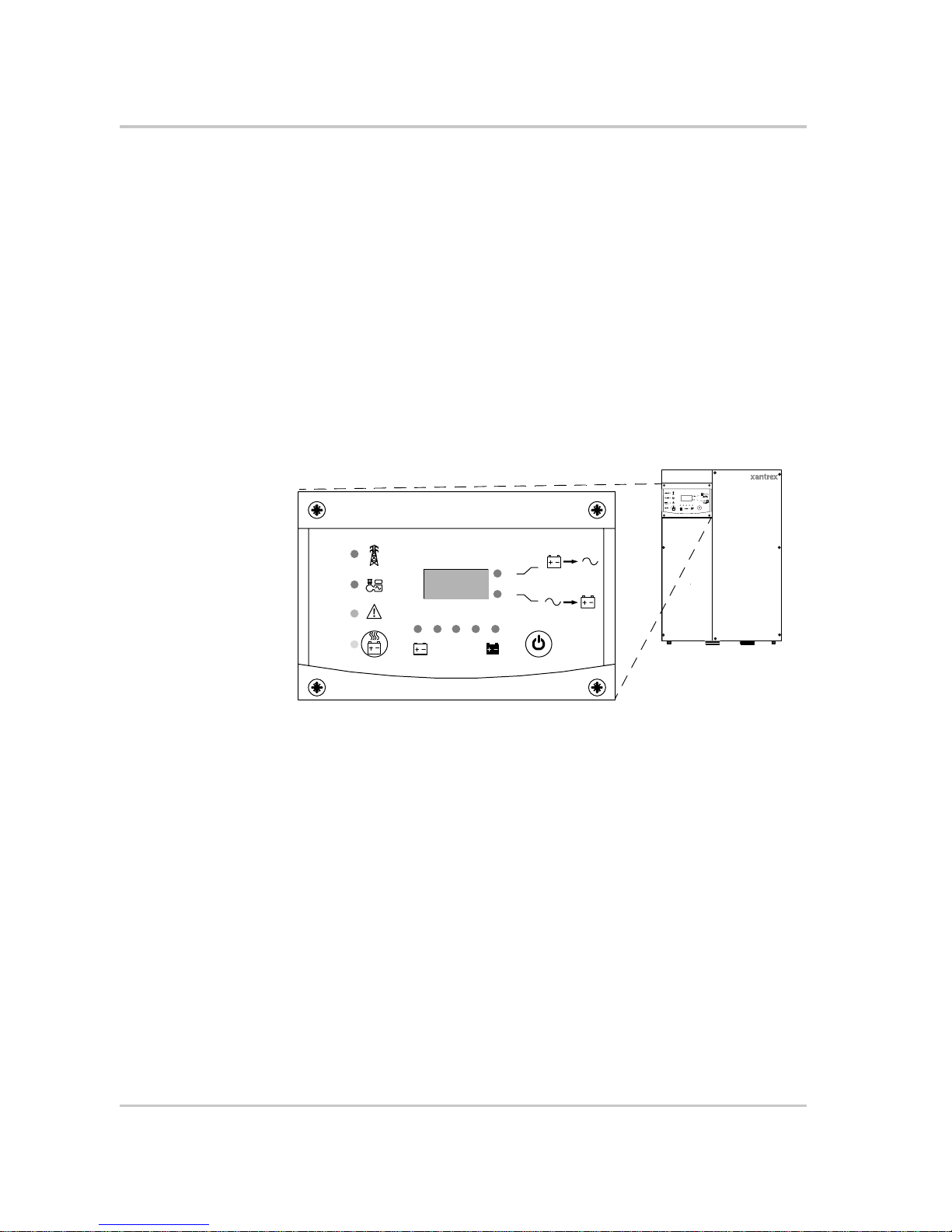
Inverter Information Panel
The Inverter Information Panel features:
• Buttons for XW Inverter/Charger on and off control, clearing faults and
warnings, and battery equalization
• Three-character display to indicate power output, charge current or
troubleshooting information
• LEDs to indicate inverter input status, inverter output status, battery
condition, and system warnings or faults.
Figure 1-1
Inverter Information Panel
Hybrid Inverter/Charger
Grid (AC1)
Gen (AC2)
Fault /
Warning
Equalize
Battery
Charging
Inverting
flashing = sell
kW
A
Monitoring the Inverter
975-0385-01-01 1–7
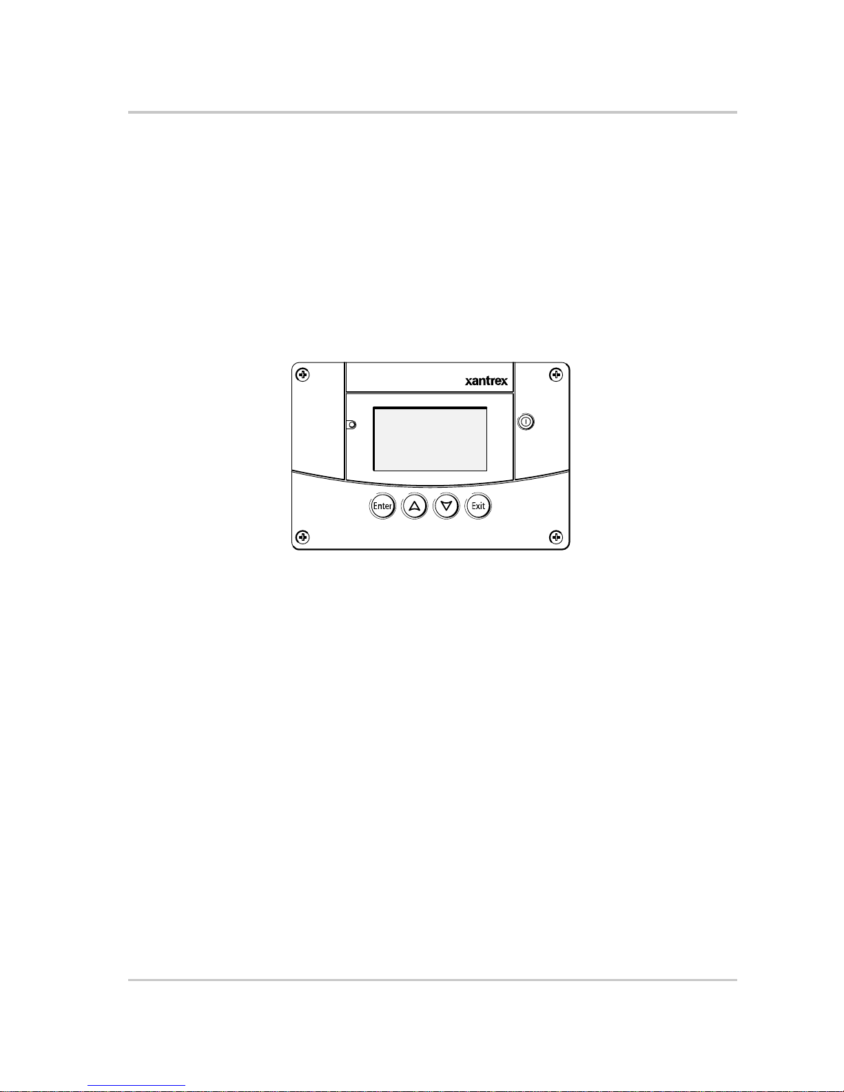
XW System Control Panel
The XW System Control Panel is required for configuring the XW Inverter/
Charger and other Xanbus-enabled system components.
The System Control Panel features:
• Liquid crystal display that provides graphics and text describing operation
and status information in real time
• LED fault and warning indicator
• Internal clock to control time-dependent XW Inverter/Charger settings
• Buttons to select configuration menus, customize XW Inverter/Charger
settings, and clear faults and warnings.
Figure 1-2
XW System Control Panel
Fault/Warning
System Control Panel II
Standby

1–8

2
Monitoring Operation
Chapter 2, “Monitoring Operation”, contains information
about monitoring XW Hybrid Inverter/Charger operation
using the Inverter Information Panel or the XW System
Control Panel.
Topics in this chapter include:
• “Monitoring Operation with the Inverter Information
Panel” on page 2–2
• “Monitoring Operation with the XW System Control
Panel” on page 2–7.
Monitoring Operation
2–2 975-0385-01-01
Monitoring Operation with the Inverter Information Panel
The Inverter Information Panel monitors a single XW Inverter/Charger. The
Inverter Information Panel displays basic information, allows you to turn the XW
Inverter/Charger on and off and start battery equalization. LEDs on the
Information Panel indicate AC input status, inverter status, battery condition, and
charging and equalization status. The LEDs and three-character display screen
also alert you to XW Inverter/Charger warning and fault conditions.
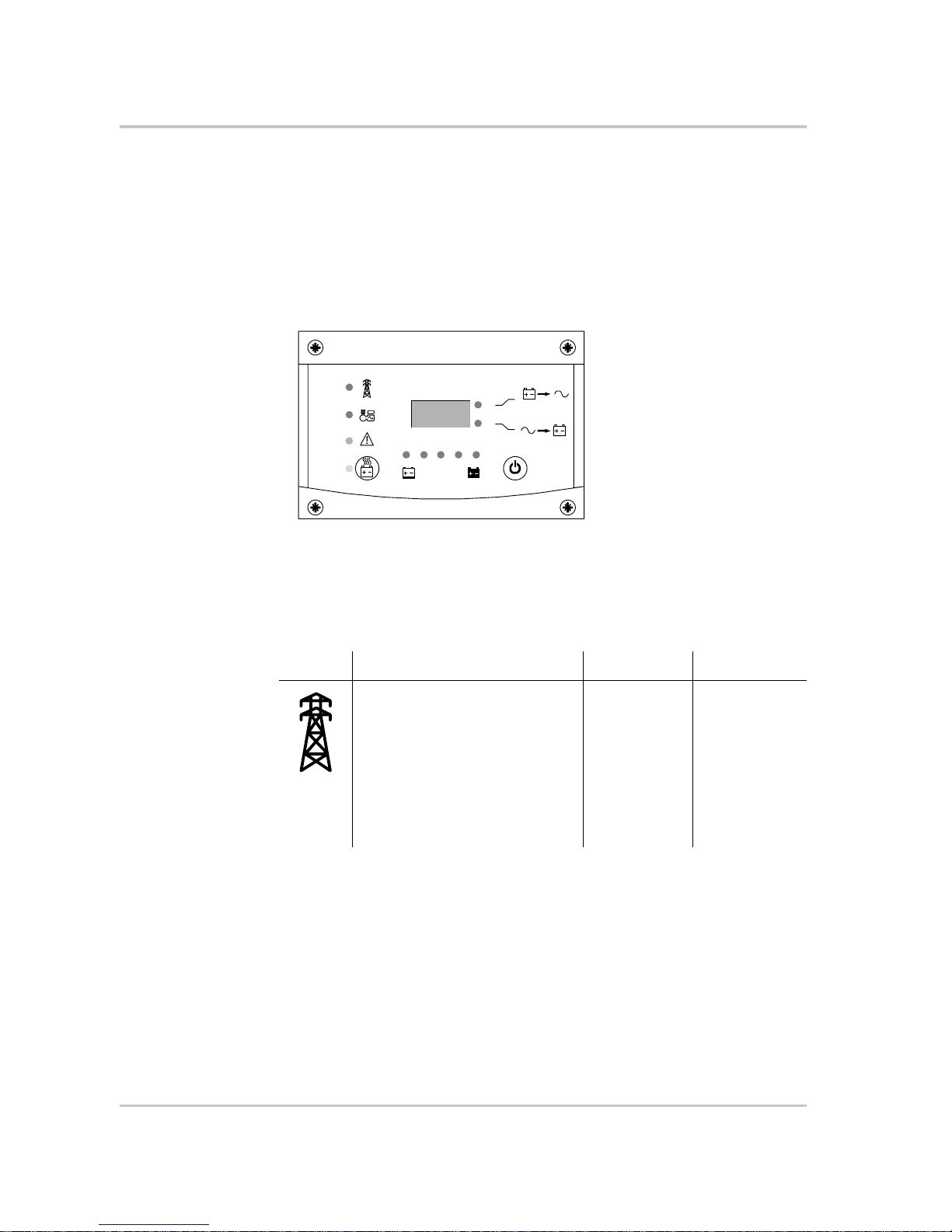
Monitoring AC Input Status
Grid (AC1) The green Grid (AC1) LED indicates the presence and status of an
AC source connected to the AC1 input.
Figure 2-1
Inverter Information Panel
Grid (AC1)
Gen (AC2)
Fault /
Warning
Equalize
Battery
Charging
Inverting
flashing = sell
kW
A
8.88
Symbol LED On LED Flashing LED Off
AC input is present and qualified.
The XW Inverter/Charger is ready to
charge batteries, sell power to the
grid, or pass AC through to the loads.
AC input is
present, within
nominal range
and is being
qualified.
The XW
Inverter/Charger
is not connected
to the grid. AC
input is not
present, or AC
input is present
but not within
nominal range.
Monitoring Operation with the Inverter Information Panel
975-0385-01-01 2–3
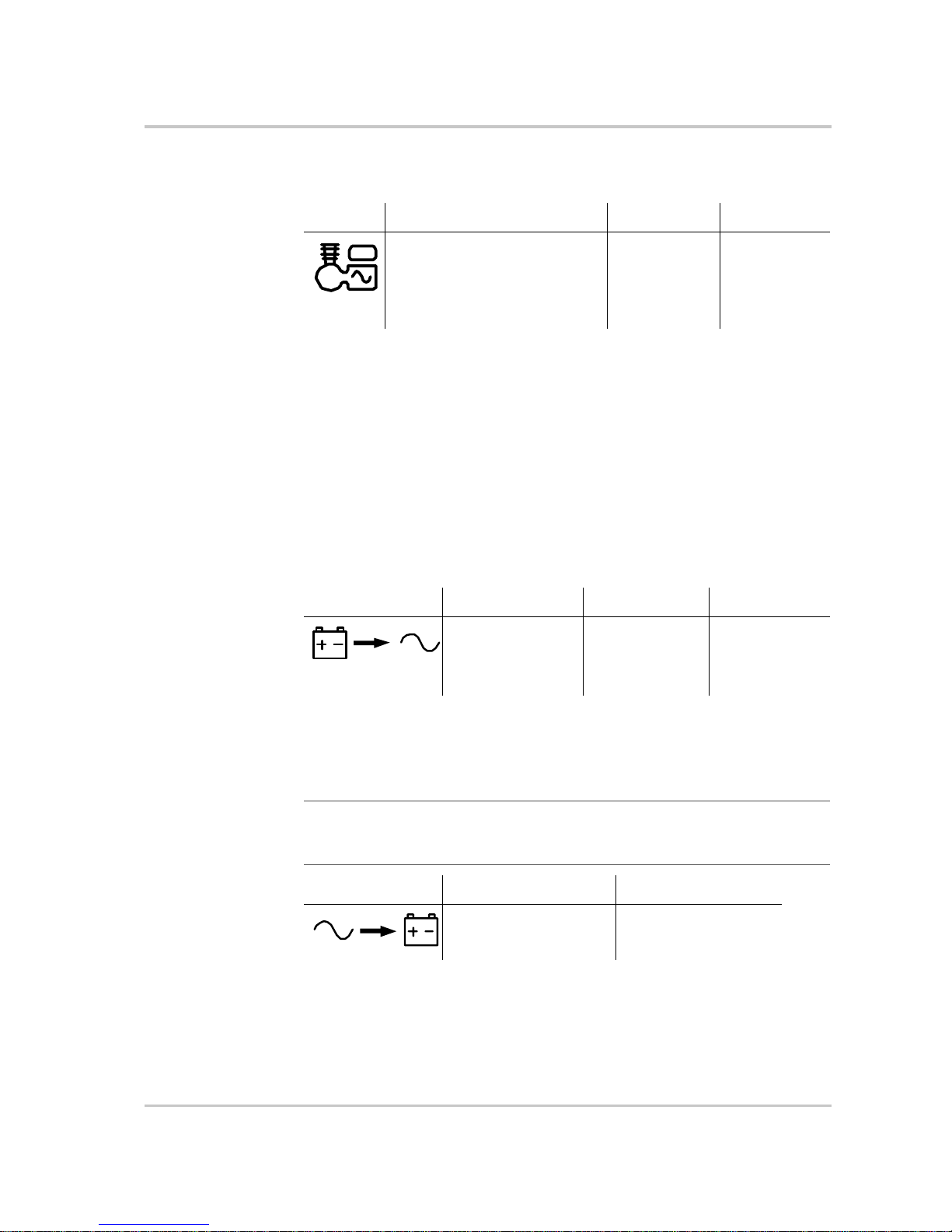
Gen (AC2) The green Gen (AC2) LED indicates the presence and status of a
generator or other auxiliary AC source on the AC2 input.
When one AC input LED is on and the other AC input LED is flashing, AC input
is present on both AC1 and AC2. However, the XW Inverter/Charger can qualify
and receive AC input from only one source at a time. The qualified source is
represented by the steadily lit LED. When two sources of AC input are present,
the XW Inverter/Charger uses the source selected under AC Priority on the
System Control Panel AC Settings menu.
Monitoring Inverter Status
The green kW LED indicates the XW Inverter/Charger is inverting DC input to
AC output. When this LED is on or flashing, the display screen shows inverter
output power in kilowatts.
Monitoring Charger Status
The green A LED indicates the XW Inverter/Charger is charging the battery bank.
When this LED is on, the display screen shows battery charging current in amps.
Symbol LED On LED Flashing LED Off
The AC source is present and AC
input is qualified. The XW Inverter/
Charger is ready to charge batteries
and pass power through to the
loads.
AC input is
present, within
nominal range
and is being
qualified.
AC input is not
present, or AC
input is present
but not within
nominal range.
Symbol LED On LED Flashing LED Off
The XW Inverter/
Charger is inverting
and producing power
for connected loads.
The XW Inverter/
Charger is selling
power to the grid.
The XW Inverter/
Charger is not
inverting.
Note: When a charge cycle ends or charging is manually disabled, the XW Inverter/
Charger does not leave charge mode immediately, and the charging LED remains on for
60 seconds.
Symbol LED On LED Off
The XW Inverter/Charger
is charging the batteries.
The XW Inverter/Charger
is not charging.
Monitoring Operation
2–4 975-0385-01-01
Monitoring Faults and Warnings
The red Fault/Warning LED indicates the presence of a fault or warning in the
system. To clear active faults, press the On/Off button momentarily.
Equalizing Batteries
Button Pressing the Equalize button (indicated by the symbol) for five seconds turns
battery equalization on and off. After this button is pressed, the XW Inverter/
Charger begins the equalization charge after the next charge cycle is complete.
Equalization functions only if AC is present and qualified and the charger is
enabled. Otherwise the inverter/charger generates a “cannot equalize” fault
(W96).
For more information, see “Equalize Charging the Batteries” on page 3–12.
LED The yellow Equalize LED indicates that the XW Inverter/Charger is equalizing
batteries.
Symbol LED On LED Flashing
&
The XW Inverter/Charger has a fault
and has stopped charging or inverting.
The LED also turns on steadily if the
unit has both a fault and a warning.
The XW Inverter/Charger has a
warning. A warning may escalate
to a fault if the warning condition
does not go away.
CAUTION: Battery damage
If improperly performed, equalization can damage your battery. Consult your battery
supplier for details on equalizing the battery type in your system.
Important:
In a system where more than one device is capable of equalizing batteries
(such as a system including multiple XW Inverter/Chargers and Solar Charge Controllers),
there is no system-wide equalization command for all devices. To equalize with multiple
devices, each would have to be enabled individually. Alternatively, equalization can be
performed using only one device. During the equalization process, one device applies the
equalization charge while the other devices continue to operate in synchronized charge
mode, typically in float (three-stage charging) or no-float (two-stage charging).
Symbol LED On LED Flashing
The XW Inverter/Charger has
begun equalizing the batteries.
Equalization has been enabled but has
not begun. The XW Inverter/Charger
must complete a charge cycle before
applying the equalization charge.

Monitoring Operation with the Inverter Information Panel
975-0385-01-01 2–5
Turning the XW Inverter/Charger On and Off
On/Off control When the XW Inverter/Charger is operating, pressing and holding the On/Off
button (#) for five seconds turns the unit off. To return the XW Inverter/Charger
to its previous operating state, press the On/Off button momentarily.
When the XW Inverter/Charger is being turned off, the other Inverter Information
Panel buttons stop working. The shutdown process cannot be cancelled. The XW
Inverter/Charger can only be turned back on once the display is blank.
Standby mode In Standby mode, the XW Inverter/Charger stops ch ar ging, in verting, and passing
through AC input. However, the unit remains powered up and present on the
Xanbus network.
To put the XW Inverter/Charger into Standby mode, press and hold the On/Off
button and the Equalize button simultaneously for about five seconds. The display
shows “Stb.” To return the XW Inverter/Charger to operating mode, press the On/
Off button momentarily.
Pressing the On/Off button momentarily while the XW Inverter/Charger is
operating clears active faults and warnings.
Single-unit
installations
In a single-unit installation, when the XW Inverter/Charger is turned off using the
On/Off button, Xanbus network power is lost. When Xanbus network power is
lost, network-connected accessories such as the Automatic Generator Start (XWAGS) and XW System Control Panel lose power and stop operating. XW Charge
Controllers continue to operate and communicate between each other if Xanbus
network power is removed.
Multiple-unit
installations
If the On/Off power button is pressed and held on a master XW Inverter/Charger
(see “Inverter Mode” on the “Multi-Unit Config Menu” on page 3–23) and an
XW-AGS is installed in the system, the unit stops inverting or charging
immediately and turns off completely in 120 seconds. During this time, the
display shows “OFF.” This interval allows the XW-AGS to stop the generator
after a “cool down” period. During the 120-second shutdown time all network
communication is blocked and the unit sends a shutdown command to all other
devices in the system. As well, the Inverter Information Panel buttons stop
working and the shutdown process cannot be cancelled. The XW Inverter/Charger
can only be turned back on once the display is blank.
In a multiple-unit installation, when a slave XW Inverter/Charger is turned off,
other XW Inverter/Chargers continue to supply Xanbus network power and the
XW-AGS and XW System Control Panel continue operating.
Monitoring Operation
2–6 975-0385-01-01
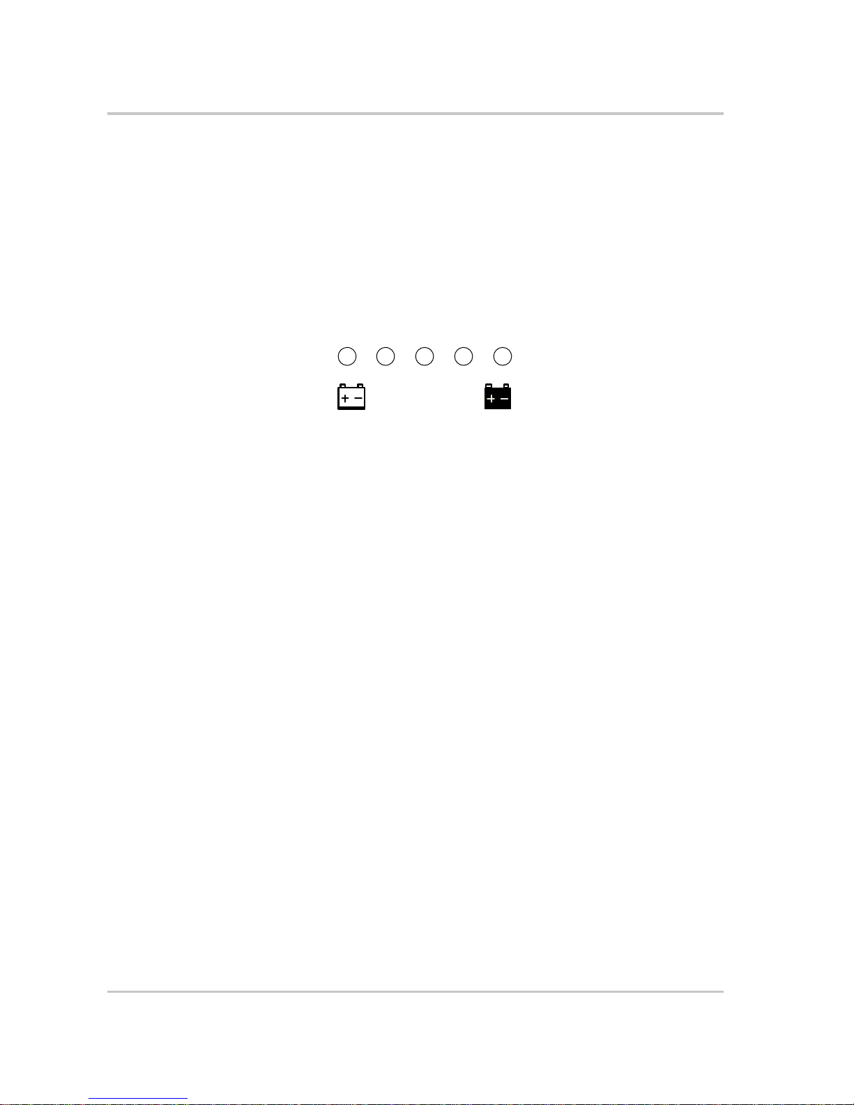
Monitoring Battery Level
The row of five LEDs indicates the approximate available capacity of the batteries
connected to the system. The capacity reading is based on current-compensated
battery voltage.
There are four battery states: empty, low, medium, and full. When the available
battery capacity is empty, no LEDs are lit. The battery is considered empty when
its depth of discharge exceeds approximately 50 per cent. When the battery
capacity is low, the leftmost two LEDs are lit. When the battery is at medium
capacity, the leftmost four LEDs are lit. When the battery capacity is full, all five
LEDs are lit.
Reading the Display Screen
The three-character display screen shows the following information about the
operating state of the XW Inverter/Charger:
• Output power in kilowatts when the XW Inverter/Char ger is inverting and the
kW LED is lit.
• Battery charger current when the XW Inverter/Charger is charging and the
A LED is lit.
• “Stb” when the XW Inverter/Charger is in Standby mode.
• “Sch” when the XW Inverter/Charger is in Search mode. See “Using Search
Mode” on page 3–8 .
• “OFF” when the on/off button is pressed and held for five seconds. “OFF” is
displayed briefly before the unit turns off.
• “– – –” briefly when the XW Inverter/Char ger is in transition between modes,
for example, qualifying AC input. The display also shows “– – –” when the
XW Inverter/Charger has been manually disconnected from renewable energy
power sources and is operating in bypass mode.
• “En” momentarily when the inverter is enabled.
• “dIS” momentarily when the inverter is disabled.
Figure 2-2
Battery Level LEDs
Battery
Discharged
Charged
 Loading...