

Page 1
XW4024-120/240-60
XW4548-120/240-60
Hybrid Inverter/Charger
XW Series Hybrid
Inverter/Charger
XW6048-120/240-60
Operation Guide
Page 2

Page 3

XW Series Inverter/Charger
Operation Guide
Page 4

About Xantrex
Xantrex Technology Inc. is a world-leading supplier of advanced power electronics and controls with products from
50 watt mobile units to one MW utility-scale systems for wind, solar, batteries, fuel cells, microturbines, and backup
power applications in both grid-connected and stand-alone systems. Xantrex products inclu de inverters, batt ery
chargers, programmable power supplies, and variable speed drives that convert, supply, control, clean, and distribute
electrical power.
Trademarks
XW Series Inverter/Charger is a trademark of Xantrex International. Xantrex is a registered trademark of Xantrex
International.
Other trademarks, registered trademarks, and product names are the property of their respective owners and are used
herein for identification purposes only.
Notice of Copyright
XW Series Inverter/Charger Operation Guide © May 2007 Xantrex International. All rights reserved.
Exclusion for Documentation
UNLESS SPECIFICALLY AGREED TO IN WRITING, XANTREX TECHNOLOGY INC. (“XANTREX”)
(
A) MAKES NO WARRANTY AS TO THE ACCURACY, SUFFICIENCY OR SUITABILITY OF ANY TECHNICAL OR OTHER
INFORMATION PROVIDED IN ITS MANUALS OR OTHER DOCUMENTATION.
(
B) ASSUMES NO RESPONSIBILITY OR LIABILITY FOR LOSSES, DAMAGES, COSTS OR EXPENSES, WHETHER SPECIAL,
DIRECT, INDIRECT, CONSEQUENTIAL OR INCIDENTAL, WHICH MIGHT ARISE OUT OF THE USE OF SUCH INFORMATION.
T
HE USE OF ANY SUCH INFORMATION WILL BE ENTIRELY AT THE USER’S RISK; AND
(C) REMINDS YOU THAT IF THIS MANUAL IS IN ANY LANGUAGE OTHER THAN ENGLISH, ALTHOUGH STEPS HAVE BEEN
TAKEN TO MAINTAIN THE ACCURACY OF THE TRANSLATION, THE ACCURACY CANNOT BE GUARANTEED. APPROVED
X
ANTREX CONTENT IS CONTAINED WITH THE ENGLISH LANGUAGE VERSION POSTED AT WWW.XANTREX.COM.
Date and Revision
May 2007 Revision A
Part Number
975-0240-01-01
Product Number
865-1000 (XW6048), 865-1005 (XW4548), 865-1010 (XW4024)
Contact Information
Telephone: 1 800 670 0707 (toll free North America)
Fax: 1 800 994 7828 (toll free North America)
Email: customerservice@xantrex.com
Web: www.xantrex.com
1 360 925 5097 (direct)
1 360 925 5143 (direct)
Page 5

About This Guide
Purpose
The purpose of this Operation Guide is to provide explanations and procedures for
configuring, operating, maintaining, and troubleshooting the XW Series Inverter/
Charger.
Scope
The Guide provides safety guidelines, detailed setup informati on, and information
about operating and troubleshooting the unit. It does not provide installation
procedures or details about particular brands of batteries, photoelectric cells, or
generators. Consult the equipment manufacturers for this information.
This manual includes information about monitoring and configuring the XW
Inverter/Charger.
For more information about XW Series products features and accessories, see the
XW Series Inverter/Charger Installation Guide.
Audience
Organization
The Guide is intended for anyone who needs to operate, configure, and
troubleshoot the XW Series Inverter/Charger. Certain configuration tasks should
only be performed in consultation with your local utility and/or an authorized
dealer.
This Guide is organized into four chapters.
Chapter 1, “Introduction”, describes the operational features of the XW Series
Inverter/Charger.
Chapter 2, “Monitoring Operation”, contains information about monitoring XW
Inverter/Charger operation using the Inverter Information Panel or the XW
System Control Panel.
Chapter 3, “Configuration” explains how to navigate through the XW System
Control Panel menus and configure the XW Inverter/Charger.,
Chapter 4, “Troubleshooting”, contains information an d pro cedures for solving
possible problems with the XW Inverter/Charger.
975-0240-01-01 iii
Page 6
About This Guide
Conventions Used
The following conventions are used in this guide.
WARNING
Warnings identify conditions or practices that could result in personal injury or loss of life
CAUTION
Cautions identify conditions or practices that could result in damage to the unit or other
equipment.
Important:
serious as a caution or warning.
Related Information
XW Power System Installation Overview (975-0238-01-01)
XW Power System Installation Guide (975-0239-01-01)
You can find more information about Xantrex Technology Inc. as well as its
products and services at www.xantrex.com
These notes describe things which are important for you to know, but not as
iv 975-0240-01-01
Page 7
Important Safety Instructions
WARNING
This chapter contains important safety and operating instructions. Read and keep this
Operation Guide for future reference.
WARNING: Limitations on use
The XW Inverter/Charger is not intended for use in connection with life support systems
or other medical equipment or devices.
1. Before using the XW Inverter/Charger, read all instructions and cautionary
markings on the XW Inverter/Charger, the batteries, and all appropriate
sections of this guide.
2. Ensure the XW Inverter/Charger is installed according to the guidelines and
procedures in the XW Power System Installation Guide.
3. Do not expose the XW Inverter/Charger to rain , snow, or spray . To reduce risk
of fire hazard, do not cover or obstruct the ventilation openings.
4. Use only attachments recommended or sold by Xantrex Technology. Doing
otherwise may result in a risk of fire, electric shock, or injury to persons.
5. To avoid a risk of fire and electric shock, make sure that existing wiring is in
good condition and that wire is not undersized. Do not operate the XW
Inverter/Charger with damaged or substandard wiring.
6. Do not operate the XW Inverter/Charger if it has received a sharp blow, been
dropped, or otherwise damaged in any way. If the XW Inverter/Charger is
damaged, see the Warranty section.
7. Do not disassemble the XW Inverter/Charger. It contains no user-serviceable
parts. See Warranty for instructions on obtaining service. Attempting to
service the XW Inverter/Charger yourself may result in a risk of electrical
shock or fire and will void your warranty. Internal capacitors remain charged
after all power is disconnected.
8. To reduce the risk of electrical shock, authorized service personnel must
disconnect both AC and DC power from the XW Inverter/Charger before
attempting any maintenance or cleaning or working on any circuits connected
to the XW Inverter/Charger. Turning off controls will not reduce this risk.
9. To reduce the chance of short-circuits, authorized service personnel must use
insulated tools when installing or working with this equipment.
975-0240-01-01 v
Page 8
Safety
Explosive gas precautions
WARNING: Explosion hazard
1. Working in the vicinity of batteries may be dangerous. Batteries can generate
explosive gases during normal operation. Therefore, you must read this guide
and follow the instructions exactly before installing or using your XW
Inverter/Charger.
2. To reduce the risk of battery explosion, follow these instructions and those
published by the battery manufacturer and the manufacturer of the equipment
in which the battery is installed.
Precautions When Working With Batteries
WARNING: Explosion or fire hazard
1. Follow all instructions published by the battery manufacturer and the
manufacturer of the equipment in which the battery is installed.
2. Make sure the area around the battery is well ventilated.
3. Never smoke or allow a spark or flame near the engine or batteries.
4. Use caution to reduce the risk of dropping a metal tool on the battery. It could
spark or short circuit the battery or other electrical parts and could cause an
explosion.
5. Remove all metal items, like rings, bracelets, and watches when working with
batteries. Batteries can produce a short circuit current high enough to weld
metal to skin, causing a severe burn.
6. Have someone within range of your voice or close enough to come to your aid
when you work near a battery.
7. Have plenty of fresh water and soap nearby in case battery acid contacts skin,
clothing, or eyes.
8. Wear complete eye protection and clothing protection. Avoid touching your
eyes while working near batteries.
9. If battery acid contacts skin or clothing, wash immediately with soap and
water. If acid enters your eye, immediately flood it with running cold water
for at least twenty minutes and get medical attention immediately.
vi 975-0240-01-01
Page 9

FCC Information to the User
This equipment has been tested and found to comply with the limits for a Class B
digital device, pursuant to part 15 of the FCC Rules. These limits are designed to
provide reasonable protection against harmful interference in a residential
installation. This equipment generates, uses and can radiate radio frequency
energy and, if not installed and used in accordance with the instructions, may
cause harmful interference to radio communications. However, there is no
guarantee that interference will not occur in a particular installation. If this
equipment does cause harmful interference to radio or television reception, which
can be determined by turning the equipment off and on, the user is encouraged to
try to correct the interference by one or more of the following measures:
• Reorient or relocate the receiving antenna.
• Increase the separation between the equipment and the receiver.
• Connect the equipment to a different circuit from that to which the receiver is
connected.
• Consult the dealer or an experienced radio/TV technician for help.
Safety
975-0240-01-01 vii
Page 10

viii
Page 11

Contents
Important Safety Instructions
1
Introduction
Basic Features- - - - - - - - - - - - - - - - - - - - - - - - - - - - - - - - - - - - - - - - - - - - - - - - - - - - - - - - - 1–2
Basic Operation- - - - - - - - - - - - - - - - - - - - - - - - - - - - - - - - - - - - - - - - - - - - - - - - - - - - - - - -1–3
Surge Performance - - - - - - - - - - - - - - - - - - - - - - - - - - - - - - - - - - - - - - - - - - - - - - - - - - - 1–4
Islanding Protection - - - - - - - - - - - - - - - - - - - - - - - - - - - - - - - - - - - - - - - - - - - - - - - - - - 1–5
Monitoring the Inverter - - - - - - - - - - - - - - - - - - - - - - - - - - - - - - - - - - - - - - - - - - - - - - - - - - 1–6
Inverter Information Panel - - - - - - - - - - - - - - - - - - - - - - - - - - - - - - - - - - - - - - - - - - - - - - 1–6
XW System Control Panel - - - - - - - - - - - - - - - - - - - - - - - - - - - - - - - - - - - - - - - - - - - - - - 1–7
2
Monitoring Operation
Monitoring Operation with the Inverter Information Panel- - - - - - - - - - - - - - - - - - - - - - - - - - - 2–2
Monitoring AC Input Status - - - - - - - - - - - - - - - - - - - - - - - - - - - - - - - - - - - - - - - - - - - - - 2–2
Monitoring Inverter Status - - - - - - - - - - - - - - - - - - - - - - - - - - - - - - - - - - - - - - - - - - - - - - 2–3
Monitoring Charger Status - - - - - - - - - - - - - - - - - - - - - - - - - - - - - - - - - - - - - - - - - - - - - - 2–3
Monitoring Faults and Warnings - - - - - - - - - - - - - - - - - - - - - - - - - - - - - - - - - - - - - - - - - - 2–3
Equalizing Batteries - - - - - - - - - - - - - - - - - - - - - - - - - - - - - - - - - - - - - - - - - - - - - - - - - - 2–4
Turning the XW Inverter/Charger On and Off - - - - - - - - - - - - - - - - - - - - - - - - - - - - - - - - - 2–5
Monitoring Battery Level - - - - - - - - - - - - - - - - - - - - - - - - - - - - - - - - - - - - - - - - - - - - - - 2–6
Reading the Display Screen - - - - - - - - - - - - - - - - - - - - - - - - - - - - - - - - - - - - - - - - - - - - - 2–6
Monitoring Operation with the XW System Control Panel - - - - - - - - - - - - - - - - - - - - - - - - - - - 2–7
XW System Control Panel Features - - - - - - - - - - - - - - - - - - - - - - - - - - - - - - - - - - - - - - - 2–7
Using the Standby Button - - - - - - - - - - - - - - - - - - - - - - - - - - - - - - - - - - - - - - - - - - - - - - 2–8
System Control Panel Navigation - - - - - - - - - - - - - - - - - - - - - - - - - - - - - - - - - - - - - - - - - 2–8
Viewing the System Control Panel Home Screens - - - - - - - - - - - - - - - - - - - - - - - - - - - 2–8
Viewing Other Screens - - - - - - - - - - - - - - - - - - - - - - - - - - - - - - - - - - - - - - - - - - - - 2–10
Reading the System Status Screen - - - - - - - - - - - - - - - - - - - - - - - - - - - - - - - - - - - - - - - - 2–11
Reading the XW Inverter/Charger Home Screen - - - - - - - - - - - - - - - - - - - - - - - - - - - - - - 2–11
Reading the Meters Screen - - - - - - - - - - - - - - - - - - - - - - - - - - - - - - - - - - - - - - - - - - - - 2–14
- - - - - - - - - - - - - - - - - - - - - - - - - - - - - - - - - - - - - - - - - - - -v
3
Configuration
Using the XW System Control Panel - - - - - - - - - - - - - - - - - - - - - - - - - - - - - - - - - - - - - - - - - 3–2
XW Inverter/Charger Setup Menu - - - - - - - - - - - - - - - - - - - - - - - - - - - - - - - - - - - - - - - - 3–2
Setting the Time and Date - - - - - - - - - - - - - - - - - - - - - - - - - - - - - - - - - - - - - - - - - - - - - - 3–3
Using the Setup Menus- - - - - - - - - - - - - - - - - - - - - - - - - - - - - - - - - - - - - - - - - - - - - - - - - - - 3–4
Inverter Settings Menu - - - - - - - - - - - - - - - - - - - - - - - - - - - - - - - - - - - - - - - - - - - - - - - - - - - 3–7
975-0240-01-01 ix
Page 12

Contents
Using the Low Battery Cut Out and LBCO Delay Settings - - - - - - - - - - - - - - - - - - - - - - - 3–7
Using Search Mode - - - - - - - - - - - - - - - - - - - - - - - - - - - - - - - - - - - - - - - - - - - - - - - - - - 3–8
Charger Settings Menu - - - - - - - - - - - - - - - - - - - - - - - - - - - - - - - - - - - - - - - - - - - - - - - - - -3–10
Battery Charger Functions - - - - - - - - - - - - - - - - - - - - - - - - - - - - - - - - - - - - - - - - - - - - -3–11
Multi-Stage Charging Process - - - - - - - - - - - - - - - - - - - - - - - - - - - - - - - - - - - - - - - - - - -3–11
Equalize Charging the Batteries - - - - - - - - - - - - - - - - - - - - - - - - - - - - - - - - - - - - - - - - - -3–13
Using Charger Block - - - - - - - - - - - - - - - - - - - - - - - - - - - - - - - - - - - - - - - - - - - - - - - - -3–14
Custom Battery Settings Menu - - - - - - - - - - - - - - - - - - - - - - - - - - - - - - - - - - - - - - - - - -3–15
AC Settings- - - - - - - - - - - - - - - - - - - - - - - - - - - - - - - - - - - - - - - - - - - - - - - - - - - - - - - - - -3–16
Grid Support Settings - - - - - - - - - - - - - - - - - - - - - - - - - - - - - - - - - - - - - - - - - - - - - - - - - - -3–17
Energy Management - - - - - - - - - - - - - - - - - - - - - - - - - - - - - - - - - - - - - - - - - - - - - - - - -3–18
Charger Block - - - - - - - - - - - - - - - - - - - - - - - - - - - - - - - - - - - - - - - - - - - - - - - - - - -3–18
Grid Support - - - - - - - - - - - - - - - - - - - - - - - - - - - - - - - - - - - - - - - - - - - - - - - - - - - -3–18
Peak Load Shaving - - - - - - - - - - - - - - - - - - - - - - - - - - - - - - - - - - - - - - - - - - - - - - -3–19
Time-of-Use Metering - - - - - - - - - - - - - - - - - - - - - - - - - - - - - - - - - - - - - - - - - - - - -3–19
Generator Support Settings - - - - - - - - - - - - - - - - - - - - - - - - - - - - - - - - - - - - - - - - - - - - - - -3–21
Auxiliary Output Settings - - - - - - - - - - - - - - - - - - - - - - - - - - - - - - - - - - - - - - - - - - - - - - - -3–21
Trigger Source Descriptions - - - - - - - - - - - - - - - - - - - - - - - - - - - - - - - - - - - - - - - - - - - -3–22
Multi-Unit Config Menu - - - - - - - - - - - - - - - - - - - - - - - - - - - - - - - - - - - - - - - - - - - - - - - - -3–23
Setting the Device Name - - - - - - - - - - - - - - - - - - - - - - - - - - - - - - - - - - - - - - - - - - - - - -3–24
Setting the Device Number - - - - - - - - - - - - - - - - - - - - - - - - - - - - - - - - - - - - - - - - - - - - -3–25
Connections Menu - - - - - - - - - - - - - - - - - - - - - - - - - - - - - - - - - - - - - - - - - - - - - - - - - - - - -3–26
Operating Without Connections - - - - - - - - - - - - - - - - - - - - - - - - - - - - - - - - - - - - - - - - - -3–27
Copying Settings From Another Unit- - - - - - - - - - - - - - - - - - - - - - - - - - - - - - - - - - - - - - - - -3–28
Resetting the XW Inverter/Charger to Default Settings- - - - - - - - - - - - - - - - - - - - - - - - - - - - -3–28
4
Troubleshooting
Troubleshooting Reference - - - - - - - - - - - - - - - - - - - - - - - - - - - - - - - - - - - - - - - - - - - - - - - 4–2
General Troubleshooting Guidelines - - - - - - - - - - - - - - - - - - - - - - - - - - - - - - - - - - - - - - - - - 4–2
Inverter Applications- - - - - - - - - - - - - - - - - - - - - - - - - - - - - - - - - - - - - - - - - - - - - - - - - - - - 4–3
Resistive Loads - - - - - - - - - - - - - - - - - - - - - - - - - - - - - - - - - - - - - - - - - - - - - - - - - - - - - 4–3
Motor Loads - - - - - - - - - - - - - - - - - - - - - - - - - - - - - - - - - - - - - - - - - - - - - - - - - - - - - - - 4–3
Problem Loads - - - - - - - - - - - - - - - - - - - - - - - - - - - - - - - - - - - - - - - - - - - - - - - - - - - - - 4–4
Very Small Loads - - - - - - - - - - - - - - - - - - - - - - - - - - - - - - - - - - - - - - - - - - - - - - - - 4–4
Fluorescent Lights and Power Supplies - - - - - - - - - - - - - - - - - - - - - - - - - - - - - - - - - - 4–4
Clocks - - - - - - - - - - - - - - - - - - - - - - - - - - - - - - - - - - - - - - - - - - - - - - - - - - - - - - - - 4–4
Searching - - - - - - - - - - - - - - - - - - - - - - - - - - - - - - - - - - - - - - - - - - - - - - - - - - - - - - 4–4
Inverter Troubleshooting - - - - - - - - - - - - - - - - - - - - - - - - - - - - - - - - - - - - - - - - - - - - - - - - - 4–5
Battery Charger Troubleshooting - - - - - - - - - - - - - - - - - - - - - - - - - - - - - - - - - - - - - - - - - - - 4–8
Faults and Warnings - - - - - - - - - - - - - - - - - - - - - - - - - - - - - - - - - - - - - - - - - - - - - - - - - - - -4–10
Warning Messages - - - - - - - - - - - - - - - - - - - - - - - - - - - - - - - - - - - - - - - - - - - - - - - - - -4–10
Warning Types - - - - - - - - - - - - - - - - - - - - - - - - - - - - - - - - - - - - - - - - - - - - - - - - - -4–11
x 975-0240-01-01
Page 13

Fault Messages - - - - - - - - - - - - - - - - - - - - - - - - - - - - - - - - - - - - - - - - - - - - - - - - - - - - 4–15
Fault Types - - - - - - - - - - - - - - - - - - - - - - - - - - - - - - - - - - - - - - - - - - - - - - - - - - - - 4–16
Inverter Operation After Faults - - - - - - - - - - - - - - - - - - - - - - - - - - - - - - - - - - - - - - - 4–16
A
Specifications
Electrical Specifications - - - - - - - - - - - - - - - - - - - - - - - - - - - - - - - - - - - - - - - - - - - - - - - - - -A–2
XW Inverter/Charger Overload Capability - - - - - - - - - - - - - - - - - - - - - - - - - - - - - - - - - - -A–3
Output Power Versus Ambient Temperature - - - - - - - - - - - - - - - - - - - - - - - - - - - - - - - - - -A–4
XW Inverter/Charger Efficiency - - - - - - - - - - - - - - - - - - - - - - - - - - - - - - - - - - - - - - - - - -A–4
Inverting Efficiency (Typical) - - - - - - - - - - - - - - - - - - - - - - - - - - - - - - - - - - - - - - - -A–4
Charging Efficiency (Typical) - - - - - - - - - - - - - - - - - - - - - - - - - - - - - - - - - - - - - - - -A–5
Sell Mode Efficiency (Typical) - - - - - - - - - - - - - - - - - - - - - - - - - - - - - - - - - - - - - - - -A–5
Mechanical Specifications - - - - - - - - - - - - - - - - - - - - - - - - - - - - - - - - - - - - - - - - - - - - - - - -A–5
Accessories - - - - - - - - - - - - - - - - - - - - - - - - - - - - - - - - - - - - - - - - - - - - - - - - - - - - - - - - - -A–6
B
Default Settings
Default Settings and Ranges - - - - - - - - - - - - - - - - - - - - - - - - - - - - - - - - - - - - - - - - - - - - - - -B–2
Inverter Menu - - - - - - - - - - - - - - - - - - - - - - - - - - - - - - - - - - - - - - - - - - - - - - - - - - - - - -B–3
Charger Menu - - - - - - - - - - - - - - - - - - - - - - - - - - - - - - - - - - - - - - - - - - - - - - - - - - - - - -B–3
Custom Battery Menu - - - - - - - - - - - - - - - - - - - - - - - - - - - - - - - - - - - - - - - - - - - - - - - - -B–4
AC Menu - - - - - - - - - - - - - - - - - - - - - - - - - - - - - - - - - - - - - - - - - - - - - - - - - - - - - - - - -B–4
Grid Support Menu - - - - - - - - - - - - - - - - - - - - - - - - - - - - - - - - - - - - - - - - - - - - - - - - - - -B–5
Gen Support Menu - - - - - - - - - - - - - - - - - - - - - - - - - - - - - - - - - - - - - - - - - - - - - - - - - - -B–5
Aux Menu - - - - - - - - - - - - - - - - - - - - - - - - - - - - - - - - - - - - - - - - - - - - - - - - - - - - - - - - -B–6
Connections Menu - - - - - - - - - - - - - - - - - - - - - - - - - - - - - - - - - - - - - - - - - - - - - - - - - - -B–6
Contents
Warranty and Return Information
Index
975-0240-01-01 xi
- - - - - - - - - - - - - - - - - - - - - - - - - - - - - - - - - - - - - - - - - - - - - - - - - - - - - - - - - - - - - - - - IX–1
- - - - - - - - - - - - - - - - - - - - - - - - - - - - - - - - - - - - WA–1
Page 14

xii
Page 15

1
Introduction
Chapter 1, “Introduction”, describes the operational features of the
XW Series Inverter/Charger.
Topics in this chapter include:
• “Basic Features” on page 1–2
• “Basic Operation” on page 1–3
Page 16

Introduction
Basic Features
System component
Congratulations on your purchase of a XW Series Inverter/Charger from Xantrex
T echnology Inc. The XW Inverter/Charger is one of the finest inverter/chargers on
the market today, incorporating state-of-the-art technology, high reliability, and
convenient control features.
Additional XW Inverter/Charger features include:
• Building block power levels—units can be installed in parallel configuration
to produce up to 18 kilowatts
• High efficiency true sine wave output
• Split phase output on 120/240 60 Hz models to simplify system configuration
by eliminating the need for an autotransformer or stacking multiple inverters
• Surge capacity to start difficult loads like well pumps, refrigerator or A/C
compressors
• Power factor-corrected (PFC) input minimizes AC power required for
charging, effectively increasing AC pass-through capacity
• High output, multi-stage charging to minimize charging time
• Easy to configure and install systems at a competitive dollar-per-watt cost
• Optional XW Automatic Generator Start allows operation with a wide range
of generators, supported through a dedicated generator input
• Supports multi-mode grid-tie operation
• Integrated transfer switch
• Temperature-controlled, variable-speed internal cooling fan. The fan turns on
when the internal temperature reaches 45 °C and reaches maximum speed at
70 °C. The fan turns off when the internal temperature falls to 40 °C.
• Housing design promotes vertical air flow through the inverter. This natural
“chimney effect” helps provide convection cooling at lower power levels, and
reduces fan run time.
• Designed for reliability and field serviceability.
The XW Inverter/Charger uses Xanbus™, a network communications protocol
developed by Xantrex, to communicate its settings and activity to other Xanbusenabled devices. You can configure and monitor the XW Inverter/Charger and
every Xanbus-enabled device in the system using an XW System Control Panel
(part number 865-1050).
1–2 975-0240-01-01
Page 17

Basic Operation
Basic Operation
The XW Series Inverter/Charger is a modular “building block” sine-wave
inverter/charger that can be used for both residential and commercial stand-alone,
grid-backup, and grid-tie applications with battery ener gy storage. The XW
Inverter/Charger is a self-contained DC to AC inverter, battery charger and
integrated AC transfer switch. Up to three inverters can be installed together in a
120/240 V split phase configuration.
Multi-unit operation Inverting For multiple XW Inverter/Chargers, the master inverter/charger
broadcasts pulses on the Xanbus network to synchronize and arbitrate operation
between the other paralleled units. This coordination of multi-unit operation
results in reduced tare loss and improved efficiency—other paralleled units stay in
low-power mode until they are needed.
For paralleled XW Inverter/Chargers, only one inverter/charger operates, and
additional devices come on-line only when the load exceeds approximately 60 per
cent of the rated output of the master inverter/charger. In a three-unit system,
additional slave units come on sequentially if the load on the master does not drop
below 60 per cent about 3 to 5 seconds after a slave unit turns on to assist the
master. When the load drops below 20 per cent of the master’s rated output, the
slave units turn off in reverse order; that is, the last slave unit to turn on will be
first to turn off.
The current sharing imbalance for a single inverter/charger does not exceed 10 per
cent of the rated maximum nominal output power. All non-utilized inverter/
chargers are off-line when no load is present.
Parallel charging When multiple XW Inverter/Chargers are charging in a
system, they synchronize charging stages to ensure efficient charging of the
battery bank. All units transition from bulk to absorption when a single unit does.
In absorption, all units must complete the absorption stage before transitioning to
the next stage. Note that units do not load share when charging. Each unit charges
batteries based on the Max Charge Rate setting and active internal (temperaturebased) deratings.
If equalize is enabled on one or more devices capable of equalization charging
(such as XW Inverter/Chargers or XW Series Solar Charge Controllers), only
those devices initiate and perform a equalize cycle after absorption. Other devices
will float (if three-stage charging is selected) or transition to AC pass-through (if
two-stage charging is selected).
When one or more XW Series Solar Charge Controllers are installed and
operating in the system, the XW Inverter/Chargers synchronize charging stage
(bulk, absorption, or float) with the charge controllers. In a similar fashion to the
XW Inverter/Charger charge behavior , charge controllers also harmonize charging
among themselves.
AC Transfer XW Inverter/Chargers monitor each other using a peer-to-peer
monitoring technique to determine the quality of AC input. If AC input is deemed
bad by any of the paralleled units, no transfer to AC occurs and the units may
975-0240-01-01 1–3
Page 18

Introduction
continually flash the AC LED on their respective information panels. If the
system was in pass-through and AC fails on any unit, all units transfer to invert
simultaneously.
Faults When an XW Inverter/Charger in a multi-unit system has a fault, only
the affected device shuts down, except in the following cases:
• When a master unit has an invert mode fault that causes it to stop inverting, a
system wide fault occurs. Invert mode faults on a slave unit shut down only
the affected slave unit.
• Battery-related faults such as battery over-temperature or over-voltage.
Other modes of operation XW inverter/chargers operate independently when
in grid support mode (including sell mode), load shave, generator support and
charger block modes. This allows units to be configured to perform a multiple of
functions independently and allowing greater flexibility in operating the system.
Auxiliary output Each XW Inverter/Charger has one programmable auxiliary output that is able to
run a small 12 V fan or operate an external relay to perform other functions, such
as to remotely start a generator (if the Xanbus-enabled XW-AGS is not used), to
disconnect external non-critical loads, or to turn on a diversion load for battery
voltage regulation.
Transfer relay The built-in transfer relay is rated for 60 amps. When an external AC source is
detected on either of its two AC inputs, the switch transfers loads from the XW
Inverter/Charger to the external power source, and then activates the battery
charger to re-charge the battery bank.
AC1 and AC2 relay The XW Inverter/Charger design does not allow the AC1 and AC2 inputs to feed
into each other. The relays controlling AC1 and AC2 input can never close
simultaneously. This design prevents generator input from feeding out to the
utility grid.
Surge Performance
Unlike many other inverters, the XW Inverter/Charger prevents voltage from
sagging dramatically during surge conditions. The XW Inverter/Charger handles
surges of over twice the inverter’s rated output with only a minimal drop in output
voltage.
1–4 975-0240-01-01
Page 19

Islanding Protection
Islanding protection is an essential safety feature that ensures no person working
on the utility grid is harmed by a distributed energy source, such an XW Inverter/
Charger. Islanding protection also prevents loads connected to the inverter from
being damaged by fluctuating utility grid input. Default software settings are
programmed into each XW Inverter/Charger at the factory to ensure it does not
“island” according to applicable safety regulations (such as IEEE 1547 and UL
1741).
As well, the XW Inverter/Charger uses a proprietary positive feedback controller
that has minimal effect on total harmonic distortion, and is guaranteed to detect
islanding conditions for all power levels, as governed by IEEE and UL standards.
In some instances it may be desirable from both a utility and customer point of
view to adjust default anti-islanding settings. For example, the XW Inverter/
Charger may experience “nuisance trips” if the grid is weak and the voltage falls
outside the allowable range specified in the regulations. It may be difficult for a
utility to upgrade the grid to eliminate this problem. With permission from the
utility, the factory settings may be changed to allow the XW Inverter/Charger to
operate over a wider grid voltage range.
These settings should only be changed by qualified service personnel, using a
special software application provided by Xantrex. Changing any values may
compromise compliance with safety regulations. Do not do so without first
consulting with the utility and agreeing on acceptable settings.
While selling power, the XW Inverter/Charger continuously monitors utility grid
voltage and frequency. If the grid voltage and frequency move beyond the XW
Inverter/Charger default ranges
the XW Inverter/Charger stops selling power to AC1 and disconnects from the
utility grid for five minutes (Five minutes is the minimum reconnect time, and is
not adjustable.) If the utility grid voltage and frequency have returned to their
nominal values when the reconnect time has expired, the XW Inverter/Charger
begins selling power again.
The Fault light on the XW Inverter/Charger information panel indicates that a
utility fault has occurred. No fault code appears on the three-character display
because the fault is with the utility grid, not the XW Inverter/Charger.
Basic Operation
1
—during a power surge or outage, for example—
The XW System Control Panel indicates a utility fault with the Fault light and a
fault message on its screen (faults F23 to F40 are utility faults—see Table 4-5 on
page 4–18). The fault cannot be manually cleared. Utility faults clear
automatically when the utility grid voltage and frequency return to their nominal
values.
1.See “Electrical Specifications” on page A–2.
975-0240-01-01 1–5
Page 20
Introduction
Monitoring the Inverter
You can monitor XW Inverter/Charger operation using either the factory-installed
Inverter Information Panel or the optional XW System Control Panel. You can
configure the inverter only with the System Control Panel.
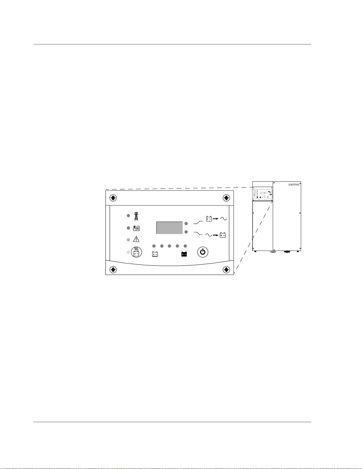
Inverter Information Panel
The Information Panel features:
• Buttons for XW Inverter/Charger on and off control, clearing faults and
warnings, and battery equalization
• Three-character display to indicate power output, charge current or
troubleshooting information
• Light-emitting diodes (LEDs) to indicate inverter input status, inverter output
status, battery condition, and system warnings or faults.
Grid (AC1)
Gen (AC2)
Fault /
Warning
Equalize
Figure 1-1
kW
A
Battery
Inverter Information Panel
Inverting
flashing = sell
Charging
Hybrid Inverter/Charger
1–6 975-0240-01-01
Page 21
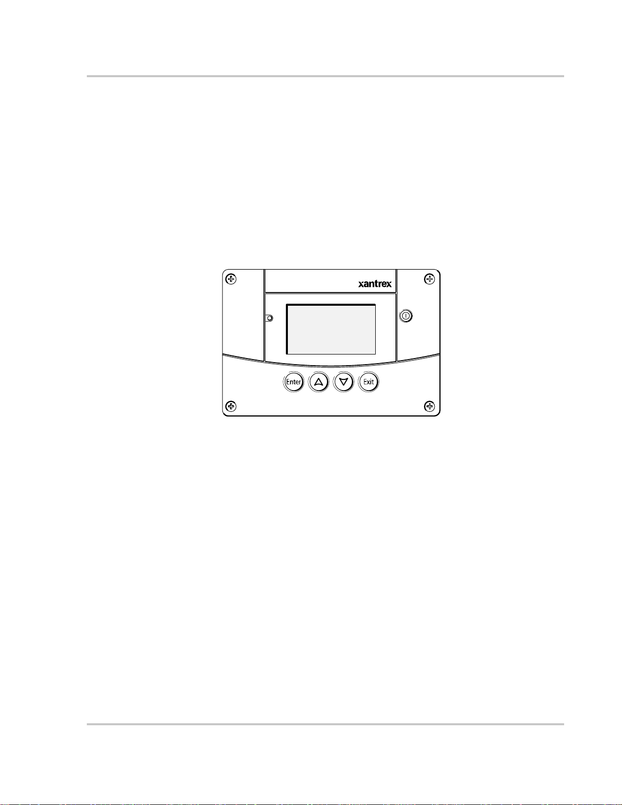
XW System Control Panel
The XW System Control Panel is required for configuring the XW Inverter/
Charger and other Xanbus-enabled system components.
The System Control Panel features:
• Liquid crystal display that provides graphics and text describing operation
and status information in real time
• LED fault and warning indicator
• Internal clock to control time-dependent XW Inverter/Charger settings
• Buttons to select configuration menus, customize inverter/charger settings,
and clear faults and warnings.
Monitoring the Inverter
Fault/Warning
Figure 1-2
Standby
System Control Panel II
XW System Control Panel
975-0240-01-01 1–7
Page 22

1–8
Page 23

2
Monitoring Operation
Chapter 2, “Monitoring Operation”, contains information about
monitoring XW Inverter/Charger operation using the Inverter
Information Panel or the XW System Control Panel.
The topics in this chapter include:
• “Monitoring Operation with the Inverter Information Panel” on
page 2–2
• “Monitoring Operation with the XW System Control Panel” on
page 2–7
Page 24
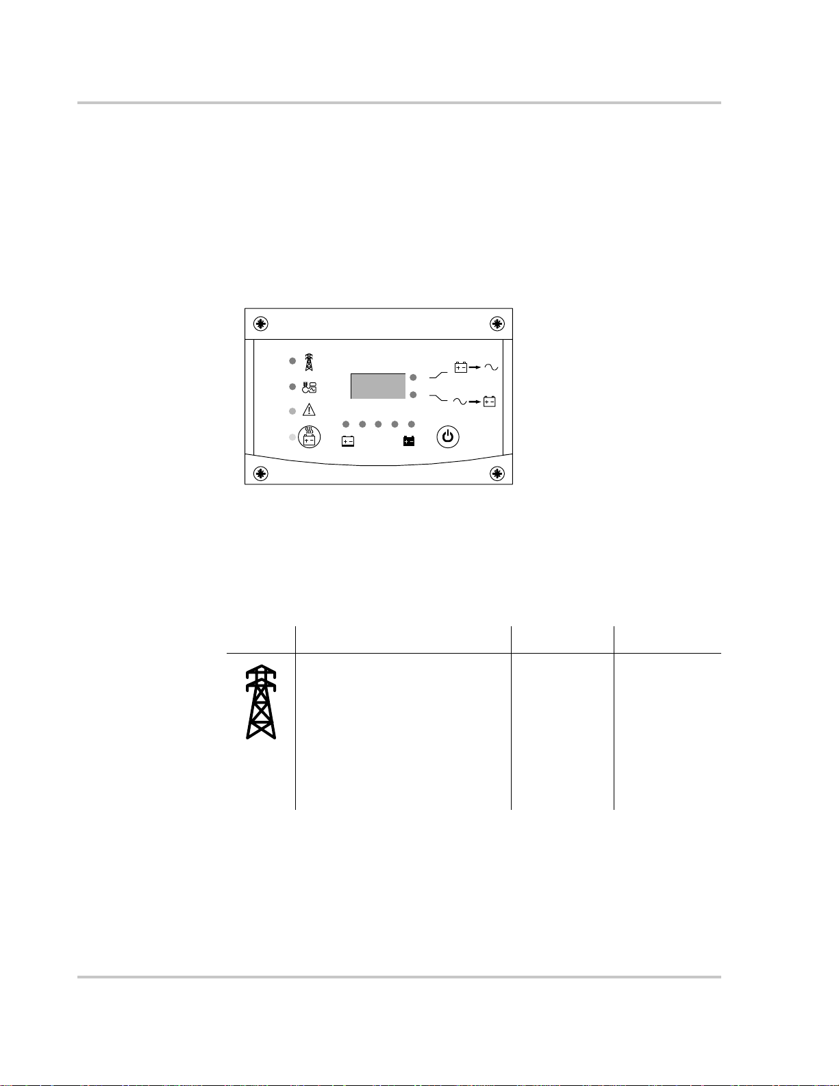
Monitoring Operation
Monitoring Operation with the Inverter Information Panel
The Inverter Information Panel displays basic information that enables you to
monitor a single XW Inverter/Charger. The Inverter Information Panel also allows
you to turn the XW Inverter/Charger on and off and start battery equalization.
LEDs on the Information Panel indicate AC input status, inverter status, battery
condition, and charging and equalization status. The LEDs and three-character
display screen also alert you to XW Inverter/Charger warning and fault
conditions.
Grid (AC1)
Gen (AC2)
Fault /
Warning
Equalize
8.88
Battery
kW
A
Inverting
flashing = sell
Charging
Figure 2-1
Monitoring AC Input Status
Grid (AC1) The green Grid (AC1) LED indicates the presence and status of AC
source connected to the AC1 input. In most installations, AC1 input is from the
utility grid. However, any AC source can be connected to the AC1 input.
Symbol LED On LED Flashing LED Off
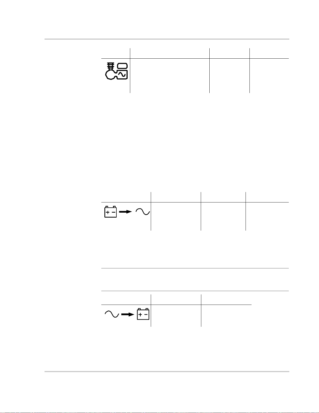
Gen (AC2) The green Gen (AC2) LED indicates the presence and status of a
generator or other auxiliary AC source on the AC2 input.
Inverter Information Panel
AC input is present and qualified.
The XW Inverter/Charger is ready to
charge batteries, sell power to the
grid, or pass AC through to the loads.
AC input is
present, within
nominal range
and is being
qualified.
The XW
Inverter/Charger
is not connected
to the grid. AC
input is not
present, or AC
input is present
but not within
nominal range.
2–2 975-0240-01-01
Page 25
Monitoring Operation with the Inverter Information Panel
Symbol LED On LED Flashing LED Off
When one AC input LED is on and the other AC input LED is flashing, AC input
is present on both AC1 and AC2. However, the XW Inverter/Charger can qualify
and receive AC input from only one source at a time. The qualified source is
represented by the LED that is on. When two sources of AC input are present, the
XW Inverter/Charger uses the source selected under AC Priority on the System
Control Panel AC Settings menu. The AC sources connected to AC1 and AC2 can
be the utility grid and a generator, or two generators.
Monitoring Inverter Status
The green kW LED indicates the XW Inverter/Charger is inverting DC input to
AC output. When this LED is on or flashing, the display screen shows inverter
output power in kilowatts.
Symbol LED On LED Flashing LED Off
The AC source is present and AC
input is qualified. The XW Inverter/
Charger is ready to charge batteries
and pass power through to the
loads.
The XW Inverter/
Charger is inverting,
and producing power
for connected loads.
The XW Inverter/
Charger is selling
power to the grid.
AC input is
present, within
nominal range
and is being
qualified.
AC input is not
present, or AC
input is present
but not within
nominal range.
The XW Inverter/
Charger is not
inverting.
Monitoring Charger Status
The green A LED indicates the XW Inverter/Charger is charging the battery bank.
When this LED is on, the display screen shows battery charging current in amps.
Note: When a charge cycle ends or charging is manually disabled, the XW Inverter/
Charger does not leave charge mode immediately, and the charging LED remains on for
60 seconds.
Symbol LED On LED Off
The XW Inverter/
Charger is charging
the batteries.
The XW Inverter/
Charger is not
charging.
Monitoring Faults and Warnings
The red Fault/Warning LED indicates the presence of a fault or warning in the
system. To clear active faults, press the On/Off button momentarily.
975-0240-01-01 2–3
Page 26
Monitoring Operation
Symbol LED On LED Flashing
The XW Inverter/Charger has a
warning. Warnings may escalate to
a fault if the warning condition
does not go away.
The XW Inverter/Charger has a fault
and has stopped charging or inverting.
The LED also turns on steadily if the
unit has both a fault and a warning.
Equalizing Batteries
Button Pressing the Equalize button (indicated by the symbol) for five seconds turns
battery equalization on and off. After this button is pressed, the XW Inverter/
Charger begins the equalization charge after the next charge cycle is complete.
Equalization functions only if AC is present and qualified and the charger is
enabled. Otherwise the inverter/charger generates a “cannot equalize” fault
(W96).
CAUTION: Battery damage
Equalization may damage your battery. Consult your battery supplier for details on
equalize charging for the battery type in your system.
Important:
(such as a system including multiple XW Inverter/Chargers and Solar Charge Controllers),
there is no system-wide equalization command for all devices. To equalize with multiple
devices, each would have to be enabled individually. Alternatively, equalization can be
performed using only one device. During the equalization process, one device applies the
equalization charge while the other devices continue to operate in synchronized charge
mode, typically in float (three-stage charging) or no-float (two-stage charging).
In a system where more than one device is capable of equalizing batteries
For more information, see “Equalize Charging the Batteries” on page 3–13
LED The yellow Equalize LED indicates that the XW Inverter/Charger is equalizing
batteries.
Symbol LED On LED Flashing
The XW Inverter/Charger has
begun equalizing the batteries.
2–4 975-0240-01-01
Equalization has been enabled but has
not begun. The XW Inverter/Charger
must complete a charge cycle before
applying the equalization charge.
Page 27

Monitoring Operation with the Inverter Information Panel
Turning the XW Inverter/Charger On and Off
On/Off control When the XW Inverter/Charger is operating, pressing and holding the On/Off
button () for five seconds turns the unit off. Pressing the On/Off button
momentarily returns the unit to its previous operating state.
When the XW Inverter/Charger is being turned off, the other Inverter Information
Panel buttons stop working. The shutdown process cannot be cancelled. The XW
Inverter/Charger can only be turned back on once the display is blank.
Standby mode In Standby mode, the XW Inverter/Char ger stops charging, inverting, and passing
through AC input. However, the unit remains powered up and present on the
Xanbus network.
To put the XW Inverter/Charger into Standby mode, press and hold the On/Off
button and the Equalize button simultaneously for about five seconds. The display
shows “Stb.” To return the XW Inverter/Charger to operating mode, press the On/
Off button momentarily.
Pressing the On/Off button momentarily while the XW Inverter/Charger is
operating clears active faults and warnings.
Single-unit
installations
Multiple-unit
installations
In a single-unit installation, when the XW Inverter/Charger is turned off using the
On/Off button, Xanbus network power is lost. When Xanbus network power is
lost, network-connected accessories such as the Automatic Generator Start (XWAGS) and XW System Control Panel lose power and stop operating. XW Charge
Controllers continue to operate and communicate between each other if Xanbus
network power is removed.
If the On/Off power button is pressed and held on a master XW Inverter/Charger
(see “Inverter Mode” on the “Multi-Unit Config Menu” on page 3–23) and an
XW-AGS is installed in the system, the unit stop s inverting/char ging immediately
and turns off completely in 120 seconds. During this time, the display shows
“OFF.” This interval allows the XW-AGS to stop the generator after a “cool
down” period. During the 120-second shutdown time all network communication
is blocked and the unit sends a shutdown command to all other devices in the
system. As well, the Inverter Information Panel buttons stop working and the
shutdown process cannot be cancelled. The XW Inverter/Charger can only be
turned back on once the display is blank.
In a multiple-unit installation, when a Slave XW Inverter/Charger is turned off,
other XW Inverter/Chargers continue to supply Xanbus network power and the
XW-AGS and XW System Control Panel continue operating.
975-0240-01-01 2–5
Page 28
Monitoring Operation
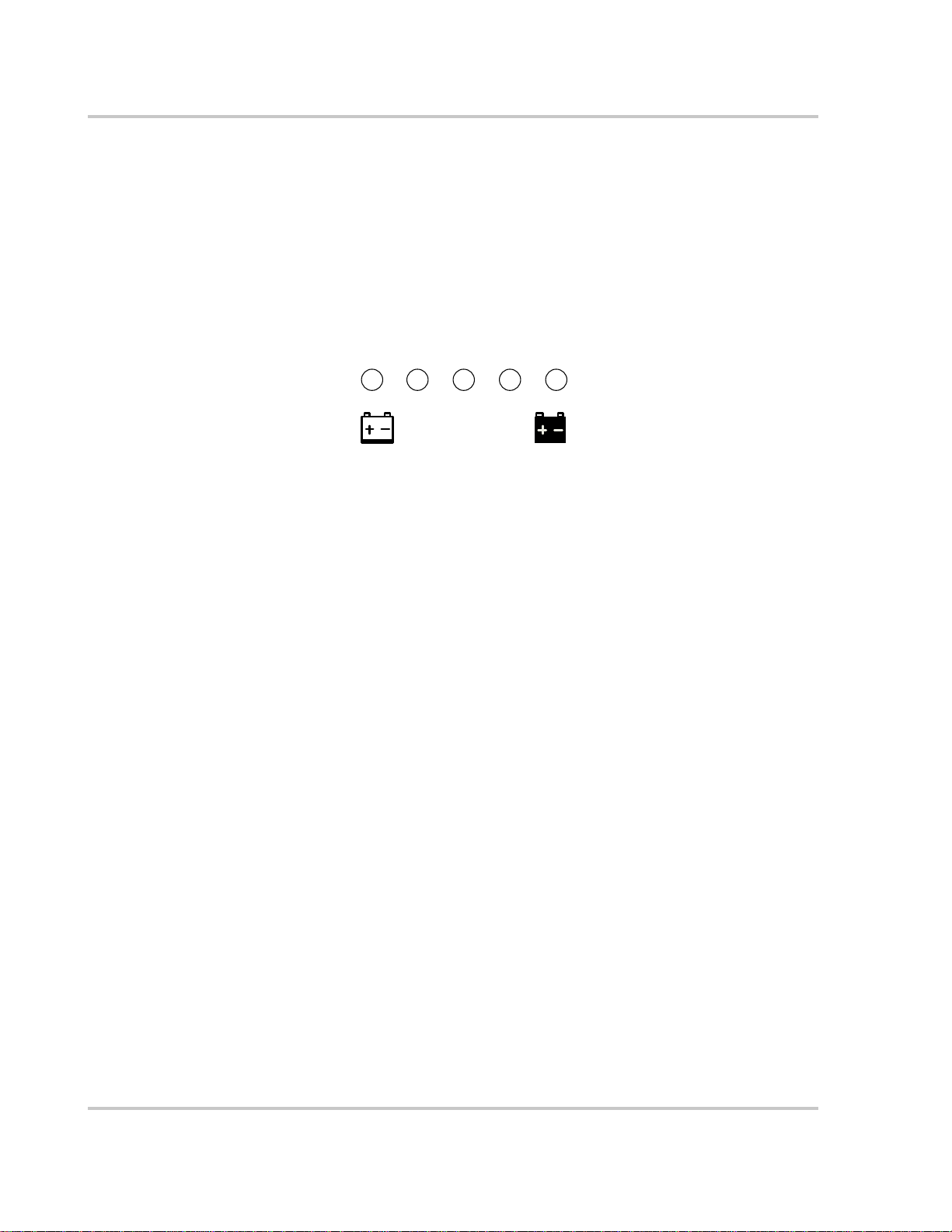
Monitoring Battery Level
The row of five LEDs indicates the approximate capacity of the batteries
connected to the system. The capacity reading is based on current-compensated
battery voltage.
There are four battery states: empty, low, medium, and full. When the battery
capacity is empty , no LEDs are lit. The battery is considered empty when its depth
of discharge exceeds approximately 50%. When the battery capacity is low, the
leftmost two LEDs are lit. When the battery is at medium capacity, the leftmost
four LEDs are lit. When the battery capacity is full, all five LEDs are lit.
Discharged
Figure 2-2
Reading the Display Screen
The three-character display screen shows the following information about the
operational state of the XW Inverter/Charger:
• Output power in kilowatts when the XW Inverter/Charger is inverting. and the
kW LED is lit.
• Battery charger current when the XW Inverter/Charger is charging and the
A LED is lit.
• “Stb” when the XW Inverter/Charger is in Standby mode.
• “Sch” when the XW Inverter/Charger is in Search mode. See “Using Search
Mode” on page 3–8.
• “OFF” when the on/off button is pressed and held for five seconds. “OFF” is
displayed briefly before the unit turns off.
• “– – –” briefly when the XW Inverter/Charger is in transition between modes,
for example, qualifying AC input. The display also shows “– – –” when the
XW Inverter/Charger has been manually disconnected from renewable energy
power sources and is operating in bypass mode.
• “En” momentarily when the inverter is enabled.
• “dIS” momentarily when the inverter is disabled.
Charged
Battery
Battery Level LEDs
2–6 975-0240-01-01
Page 29
Monitoring Operation with the XW System Control Panel
Monitoring Operation with the XW System Control Panel
The XW System Control Panel provides remote configuration and monitoring
capability for the XW Inverter/Charger and other Xanbus-enabled devices in the
power system.
You can monitor XW Inverter/Charger operation on the XW System Control
Panel using the:
• System Status screen (see page 2–11)
• XW Inverter/Charger Home screen (see page 2–11)
• XW Inverter/Charger Meters Menu (see page 2–14).
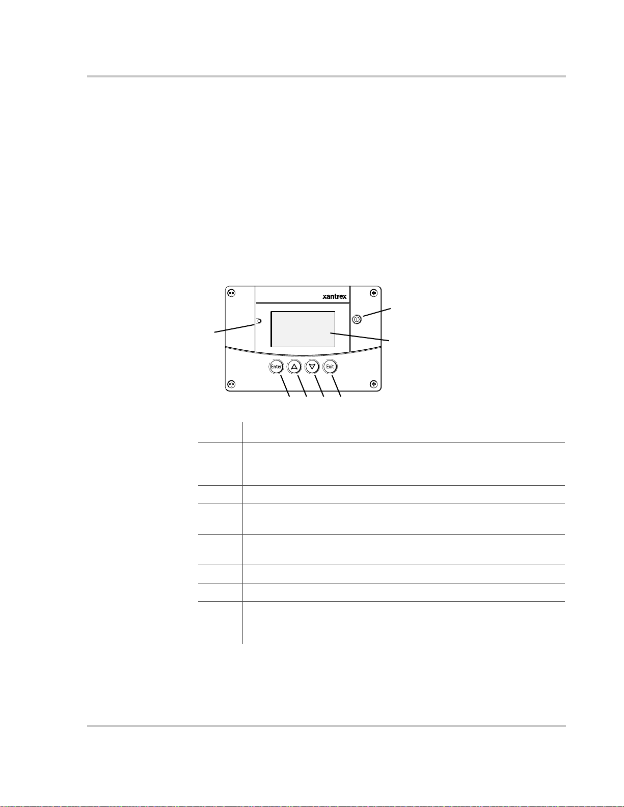
XW System Control Panel Features
7
Fault/Warning
1
Standby
6
System Control Panel II
2345
Feature Description
1 Fault/Warning light indicates a device has a fault or warning condition and
requires attention. The light flashes when a warning occurs, and turns on
steadily when a fault occurs.
2 Enter button confirms selection of a menu item or displays the next screen.
3 Up arrow button scrolls upwards through screen text or increases a selected
value.
4 Down arrow button scrolls downwards through screen text or decreases a
selected value.
5 Exit button cancels selection of a menu item or displays the previous screen.
6 Screen shows menus, settings, and system information.
7 Standb y button disables inverting and charging on all XW Inverter/Chargers
in the system when pressed for one to two seconds. To enable inverting and
charging, press the Standby button again.
975-0240-01-01 2–7
Page 30

Monitoring Operation
Using the Standby Button
The Standby button has two functions, depending on how it is pressed. Th e
Standby button can disable inverting and charging for all XW Inverter/Chargers in
the system, or, when pressed simultaneously with the Exit button, put the entire
system into Standby mode.
Pressing the Standby button produces the same result as disabling “Invert” and
“AC Charge” from the System Settings menu on the XW System Control Panel.
Pressing the Standby button momentarily affects only XW Inverter/Chargers; it
does not affect Charge Controller operation. After disabling inverting and
charging with the Standby button, the system continues to pass AC input through
to the loads, and “– – –” is displayed on the Inverter Information Panel.
Pressing the Exit and Standby buttons at the same time puts the entire XW power
system (including Charge Controllers) into Standby mode. In Standby mode, the
XW Inverter/Chargers stop passing AC input through to the loads, and “Stb” is
displayed on Inverter Information Panel.
After the keypress command to enter Standby mode, the XW-AGS (if installed)
shuts down the generator (if it is running) after a cool-down cycle.
System Control Panel Navigation
This section describes the different types of screens and menus on the System
Control Panel. To monitor XW Inverter/Charger operation, it is helpful to know
how to locate these screens and menus.
Viewing the System Control Panel Home Screens
The top level screens on the System Control Panel are the Startup screen, the
System Status screen and the Device Home screens. After power is applied and
the Startup screen appears, the System Control Panel displays the System Status
screen. The Device Home screens for the XW Inverter/Charger and other devices
in the system can be viewed by pressing the up and down arrows, as shown in
Figure 2-3.
2–8 975-0240-01-01
Page 31
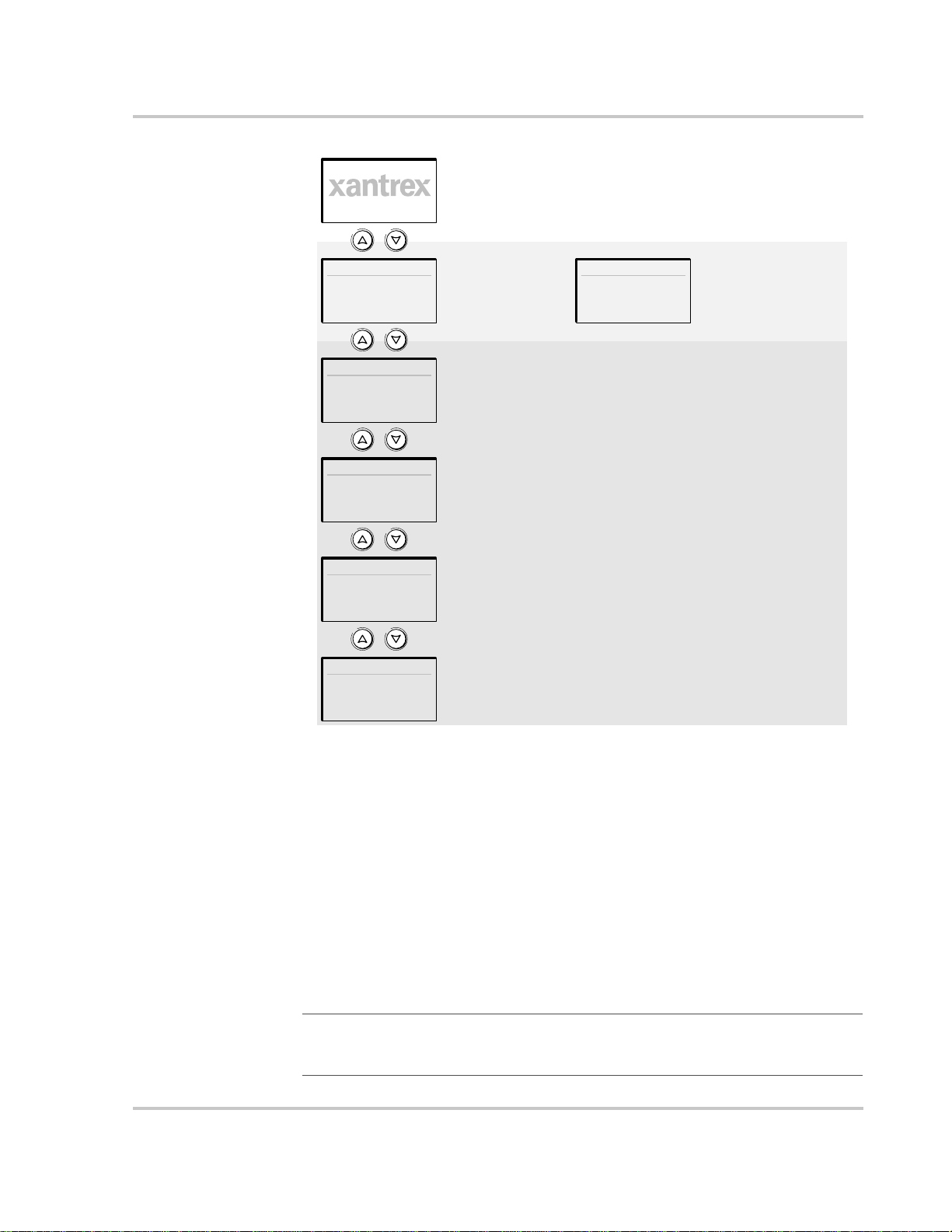
Startup screen
Monitoring Operation with the XW System Control Panel
Appears for a few seconds after the system starts up
or when the system has been reset.
System Status
System
Status screen
XW6048:Home
XW
Inverter/Charger
Home screen
Device 2:Home
Device 2
Home screen
Device 3:Home
Device 3
Home screen
Device n:Home
Device n
Home screen
Press Enter to view
Select Device menu.
Press Enter from a Device Home screen
to view the Device Setup menu.
The number of Home screens depends on
the number of Xanbus-enabled devices
installed in the system.
Select Device
Select Device
menu
Select device from list
and press Enter to view
Device Setup menu.
Figure 2-3
System Control Panel
Top Level
Screens
System Status Screen
The System Status screen appears after the Startup screen. The System Status
screen displays aggregated status information for the entire power system. For
example, a single system may have three Xanbus™ network-connected XW
Inverter/Chargers, two XW Solar Charge Controllers, one XW-Automatic
Generator Start module and one XW System Control Panel all connected to a
single battery bank, a single generator and a common utility grid.
The System Status screen always features a “Menu” arrow pointing to the Enter
button. Pressing Enter takes you to the Select Device menu. For more
information, see “Reading the System Status Screen” on page 2–11.
Important:
viewing, you can always return to the starting point—the System Status screen—by
pressing Exit repeatedly until the screens stop changing.
975-0240-01-01 2–9
If you are uncertain which System Control Panel screen or menu you are
Page 32

Monitoring Operation
Viewing Other Screens
XW Inverter/Charger Home Screen
The XW Inverter/Charger Home screen is the first of the Device Home screens.
Each XW Inverter/Charger installed in the system has its own Home screen.
The XW Inverter/Charger Home screen displays status information for the XW
Inverter/Charger. The screen appearance varies with the status of the inverter/
charger (Standby, Inverting, Char ging, AC Bypass, Search, or Equalize). For more
information, see “Reading the XW Inverter/Charger Home Screen” on page 2–11.
To display the XW Inverter/Charger Home screen:
u Press the down arrow key from the System Status screen.
This section describes the next level of screens and menus on the System Control
Panel.
Select Device Menu
The Select Device menu displays a list of Xanbus-enabled devices in the system,
including the XW Inverter/Charger and the System Control Panel. The Select
Device menu is where you can access the Setup menus for each device in the
system. The length of the Select Device menu depends on how many Xanbusenabled devices are installed.
The Select Device menu also contains the Clock menu (where the time and date
are set) and the System Settings menu (where system-level settings can be
configured). The System Settings, SCP, and Clock menus are always available
from the Select Device menu, regardless of the number of Xanbus-enabled
devices installed.
To display the Select Device menu:
u Press Enter from the System Status screen.
Device Setup Menus
Device Setup menus display status information (on the Meters screen) and
changeable settings. Changeable settings are identified by the square brackets [ ]
around values in the right-hand column.
To display the Setup menu for a device:
u Highlight the device name on the Select Device menu and press Enter.
-OrFrom the Device Home screen, press Enter.
2–10 975-0240-01-01
Page 33

Select Device menu
Select Device
XW6048
Monitoring Operation with the XW System Control Panel
XW Inverter/Charger
Setup menu
XW6048 00: Setup
Meters
[Enabled]
Select device from list
and press Enter to view
Device Setup menu
[Disabled]
[Disabled]
[Enabled]
[Bulk]
[Disabled]
[Operating]
Figure 2-4
Selecting a Device Setup Menu
Reading the System Status Screen
The System Status screen displays:
• Qualified AC source (if applicable) and total power to and from the source
• Battery voltage and capacity level
• Net battery input or output current
• Total inverter loading.
System Status
20.4A 53.9V
115V 3202W
menu
“Menu” arrow indicates the Enter
button. Pressing Enter displays
the Select Device menu.
Figure 2-5
System Status Screen
E--F
1235W
Line 1: Battery voltage and input/output current
Line 2: Battery level meter
Line 3: Power supplied to loads
Line 4: AC input source and line-to-neutral
voltage (averaged between L1 and L2). Bottom
left corner displays “AC1” or “AC2” depending on
the active input source. When selling to the grid,
the power displayed is negative.
Reading the XW Inverter/Charger Home Screen
The XW Inverter/Charger Home screen displays real-time operational data
specific to the XW Inverter/Charger. The XW Inverter/Charger status changes
according to the states described in Table 2-1 on page 2–12.
To view the XW Inverter/Charger Home screen:
u On the System Home screen, press the down arrow button until the XW
Inverter/Charger Home screen appears.
975-0240-01-01 2–11
Page 34

Monitoring Operation
XW6048 00:Home
-26.4A 51.9V
0.0V 0W
setup system
“Setup” arrow indicates the Enter
button. Pressing Enter displays the
XW Inverter/Charger setup menu.
Figure 2-6
XW Inverter/Charger Home Screen
Invert
1250W
Top Line: Device name and number
Line 1: Inverter/charger status
Line 2: Battery current (in + or out –) and voltage
Line 3: Power supplied to loads
Line 4: AC in status
“System” arrow indicates the Exit
button. Pressing Exit displays the
System Home screen.
Pressing the down arrow button from the XW Inverter/Charger Home screen
displays the Home screens for other XW Inverter/Chargers and other Xanbusenabled devices in the system.
Table 2-1
XW Inverter/
Charger Status Displayed When...
Invert The XW Inverter/Charger is supplying power to loads by inverting power from the batteries. AC
Qualifying AC The XW Inverter/Charger is determining if AC input is within a usable voltage and frequency
XW Inverter/Charger Home Screen States
input from the utility or generator is absent or out of nominal range.
range. “Qualifying AC” is also displayed when the XW Inverter/Charger is awaiting application
of AC power or a command to enable invert mode.
Charging The XW Inverter/Charger is charging the batteries from qualified AC input from the utility grid
or a generator. The char ge state is in transition to either Bulk, Absorption, Float or Equalize. AC
input is also passed through to the load while charging.
Bulk The XW Inverter/Charger is bulk charging the batteries from qualified AC input from the utility
grid or a generator. AC input is also passed through to the load while bulk charging.
Absorption The XW Inverter/Charger is absorption charging the batteries from qualified AC input from the
utility grid or a generator. AC input is also passed through to the load while absorption charging.
ABS Finish The XW Inverter/Charger has completed the absorption stage and is waiting for other chargers
in the system to complete absorption. This status can occur only when there is another device (an
inverter/charger or charge controller) also charging the battery.
Float The XW Inverter/Charger is float charging the batteries from qualified AC input from the utility
grid or a generator. The XW Inverter/Charger is set for three-stage charging. AC input is also
passed through to the load while float charging.
CHG Finish The XW Inverter/Charger has completed charging or the charge cycle has been interrupted and
is transitioning to the next state. This stage last about one minute, while the battery is allowed to
settle. The delay keeps the inverter/charger from unnecessarily transitioning to Grid Support (if
enabled) after a charge cycle.
2–12 975-0240-01-01
Page 35
Monitoring Operation with the XW System Control Panel
Table 2-1
XW Inverter/
Charger Status Displayed When...
Fault The XW Inverter/Charger has an active fault. The Fault/Warning light on the System Control
Gen Support There is AC input from the generat or, and the XW Inverter/Charger is supporting the generator
Grid Support There is AC input from the utility and the XW Inverter/Charger is supporting the utility grid by
XW Inverter/Charger Home Screen States
Panel is on.
by supplying additional power to the critical loads.
The XW Inverter/Charger supports the generator (or other power source connected to the AC2
input) when the AC load current drawn from AC2 exceeds 80 per cent of the AC2 breaker
setting or GenSup Amps setting for 1 to 2 seconds.
The XW Inverter/Charger uses stored DC capacity to load share with the generator until the total
AC load current (generator plus inverter output) drops by 2 amps plus 10 per cent of the GenSup
Amps setting for 6 seconds.
For example if GenSup Amps is set to 10 amps, the inverter starts to support when the load
exceeds 10 amps for 2 seconds and stops when it drops more than 3 amps below the GenSup
Amps setting, or 7 amps (2 amps plus 10 per cent of 10 amps = 3 amps).
The system can enter this state if the battery voltage is above the Low Batt Cut Out setting and
Gen Support is enabled. See “Generator Support Settings” on page 3–21.
supplying additional power to the critical loads.
The XW Inverter/Charger supports the utility grid by limiting the power drawn from the utility
to less than 10 per cent of the load demand. This mode is desirable for using excess energy from
auxiliary DC sources like PV, while still maintaining a charged battery bank. No power is sold to
the utility in this mode.
The XW Inverter/Charger uses stored DC capacity to support the grid until the total AC load
current (grid plus inverter output) drops by 2 amps plus 10 per cent of the Load Shave Amps
setting for 6 seconds.
The XW Inverter/Charger enters this state only when the Grid Support is set to “On” and battery
voltage is above the Grid Supp Volts setting. See “Grid Support Settings” on page 3–17.
Load Shaving There is AC input from the utility, and the XW Inverter/Charger is supporting the utility grid
when the current required to power the loads rises above the Load Shave Amps setting between
the Load Shave Start and Load Shave Stop times set on the Grid Support menu.
Many utilities impose a surcharge on their customers based on the peak load used by a facility.
When load shaving, the XW Inverter/Charger uses stored DC capacity to reduce the peak load
on the utility grid and keep current draw from the grid equal to or under the Load Shave Amps
setting. The XW Inverter/Charger enters this state only when Grid Support is enabled, the Load
Shave time window is valid and the load draw exceeds the Load Shave Amps setting. See “Grid
Support Settings” on page 3–17.
Search Search Mode is enabled and the XW Inverter/Charger is standing by , waiting to begin inverting.
See “Using Search Mode” on page 3–8.
SellToGrid The XW Inverter/Charger is grid tied (grid voltage and frequency are within the limits specified
by UL1741) and selling power to the utility grid. Both Grid Support and Sell must be enabled in
order to sell power back to the utility. See T able 3-1 on page 3–3 and “Grid Support Settings” on
page 3–17.
975-0240-01-01 2–13
Page 36
Monitoring Operation
Table 2-1
XW Inverter/
Charger Status Displayed When...
Standby The unit is placed in Standby mode using the XW System Control Panel “Mode” on the Setup
Passthru The AC connected to the AC1 or AC2 input is passing directly through the XW Inverter/Charger
Equalize Equalization has been turned on and the XW Inverter/Charger is equalizing the batteries after
XW Inverter/Charger Home Screen States
menu or the Standby button on the SCP or using the Standby key press (On/Off and
Equalization) on the Inverter Information Panel.
to the loads. The batteries are not being charged in this state.
completing a full charge cycle. The equalize screen (see Figure 2-7) shows battery voltage, input
current, battery temperature, and equalization time elapsed and remaining.
XW6048 00:Equalize
48V +5A 95
31 min.
menu
Figure 2-7
XW Inverter/Charger Home Screen (Equalize)
60 min.
o
F
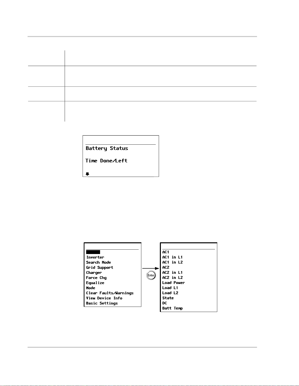
Reading the Meters Screen
The Meters screen displays total system power production, grid voltage and
current status, and load voltage and current status.
To view the Meters screen:
u On the XW Inverter/Charger setup menu, highlight “Meters” and press Enter.
XW6048 00: Setup
Meters
Figure 2-8
[Enabled]
[Disabled]
[Disabled]
[Enabled]
[Bulk]
[Disabled]
[Operating]
Viewing the Meters Screen
Meters
3200W 4500VA
21.1A 120V
21.1A 120V
0W 0VA
0.0A 0V
0.0A 0V
3200W 4500VA
21.1A 120V
21.1A 120V
Float
3.7A 57.4V
20°C
2–14 975-0240-01-01
Page 37

Monitoring Operation with the XW System Control Panel
Table 2-2
Screen Item Description
AC1 AC input power connected to the XW Inverter/Charger AC1 terminals, in Watts and Volt-Amps.
AC1 in L1 AC input voltage and current connected to the XW Inverter/Charger AC L1 terminals. This input
AC1 in L2 AC input voltage and current connected to the inverter’s AC L2 terminals. This input voltage
AC2 AC input power connected to the XW Inverter/Charger AC2 terminals, in Watts and Volt-Amps.
AC2 in L1 AC input voltage and curren t supplied to the inverter/charger from the AC2 L1 input. This meter
AC2 in L2 AC input voltage and curren t supplied to the inverter/charger from the AC2 L2 input. This meter
Load Power Power consumed by the AC loads, in Watts and Volt-Amps.
Load L1 AC voltage and current supplied from L1 to the AC loads.
Meters Screen
AC1 is assumed to be connected to the utility grid, but can be connected to any other 240 Vac
source.
voltage display may drift slightly before the inverter has synchronized to the grid.
display may drift slightly before the inverter has synchronized to the grid.
AC2 is assumed to be connected to a generator, but can be connected to any other 240 Vac source.
indicates the inverter/charger is drawing power from the generator to charge the battery or power
the AC loads.
indicates the inverter/charger is drawing power from the generator to charge the battery or power
the AC loads.
Load L2 AC voltage and current supplied from L2 to the AC loads.
State Operating state of the XW Inverter/Charger. For more information, see Table 2-1 on pag e 2–12.
DC Charging current and battery voltage.
Batt Temp Battery Temperature, as read by the BTS. If the BTS is not installed, this reads “NotAvailable.”
975-0240-01-01 2–15
Page 38

2–16
Page 39

3
Configuration
Chapter 3, “Configuration” explains how to navigate through the XW
System Control Panel menus and configure the XW Inverter/Charger.
Topics in this chapter include:
• “Using the XW System Control Panel” on page 3–2
• “Using the Setup Menus” on page 3–4
Page 40

Configuration
Using the XW System Control Panel
The XW Inverter/Charger is configured using the XW System Control Panel. The
System Control Panel provides access to settings relating to AC input and output,
battery charging, and grid-tie operation.
WARNING: Risk of fire and shock hazard
The following information is for qualified installation/service personnel only. Incorrect
configuration can lead to battery damage and risk of fire.
Consult the local utility before changing any Grid Support settings. Before changing XW
Inverter/Charger settings, you must be familiar with the settings and the system-wide
impact of changing those settings. Setting these parameters incorrectly could damage
connected equipment (such as batteries) or could severely affect the performance of your
system.
XW Inverter/Charger Setup Menu
The XW Inverter/Charger Setup menu is accessible either from the System Home
screen or from the XW Inverter/Charger Home screen.
To navigate to the XW Inverter/Charger Setup menu:
1. From the System Home screen, press Enter to view the Select Device menu.
Go to step 2.
Or
From the XW Inverter/Charger Home screen, press Enter. The XW Inverter/
Charger Setup menu appears.
2. Highlight the XW Inverter/Charger device name, and press Enter.
XW6048 00: Setup
Meters
[Enabled]
[Disabled]
[Disabled]
[Enabled]
[None]
[Disabled]
[Operating]
Note: The System Control Panel displays only
four lines of the Setup menu at one time. To
view additional settings, press the Down
arrow button.
Figure 3-1
3–2 975-0240-01-01
XW Inverter/Charger Setup menu
Page 41

Using the XW System Control Panel
Table 3-1
Menu Item Description
Meters Displays the Meters screen.
Inverter Enables or disables the inverter.
Search Mode Turns Search Mode on and off. See “Using Search Mode” on page 3–8.
Grid Support Enables or disables grid-interactive inverter/charger features, such as Peak Load Shaving
Charger Enables or disables the charger.
Force Chg Manually changes the charge stage to either Bulk or Float (when 3-Stage cycle is
Equalize Enables or disables battery equalization.
Mode Selects the XW Inverter/Charger operating mode: Operating or Standby. The red Standby
Clear Faults/Warnings Clears any active faults or warnings. If the fault or warning condition is still present, the
View Device Info Displays the Device Info screen. On the Device Info screen you can view the Warning
XW Inverter/Charger Setup menu
and Grid Sell mode. See “Grid Support Settings” on page 3–17. To allow Grid Support to
function after battery charging has completed, it is recommended to set the Charge Cycle
to 2-Stage. See “Charger Settings Menu” on page 3–10.
selected) or Bulk or NoFloat (when 2-Stage cycle is selected).
button on the System Control Panel has similar functionality (see “XW System Control
Panel Features” on page 2–7).
fault or warning message may reappear.
Log, Fault Log and Event Log.
Basic Settings Select to displ a y and/or adjust the basic XW Inverter/Charger settings. See “Using the
Setup Menus” on page 3–4.
Setting the Time and Date
XW Inverter/Charger advanced features such as peak load shaving, Charger
Block, and time-stamped events (faults and warnings and logged historical data)
require that the system be set to the correct time. The System Control Panel has an
internal clock that controls the time for all Xanbus-enabled devices in the system.
You can set the time, time format, and date on the Clock menu. The Clock menu is
accessible on the Select Device menu.
For more information, see “Setting the Time” and “Setting the Date” in the XW
System Control Panel Owner’s Guide.
975-0240-01-01 3–3
Page 42

Configuration
Using the Setup Menus
Basic menu The XW Inverter/Charger configuration settings can be viewed in Basic and
Advanced formats (see Figure 3-3, “Basic and Advanced Settings” on page 3–6).
The Basic settings include configuration items you may have to adjust routinely,
or as part of initial setup.
Advanced menu The Advanced settings option gives you access to the full range of settings for the
XW Inverter/Charger, including everything displayed on the Basic menu. As a
safeguard against unintended advanced configuration, the XW Inverter/Charger
displays the Basic settings by default. To view the Advanced settings, you must
perform a special keypress.
WARNING: Risk of fire and shock hazard
The Advanced settings are intended for qualified installation/service personnel only.
Incorrect configuration can lead to battery damage and risk of fire.
Consult the local utility before changing any Grid Support settings. Before changing XW
Inverter/Charger settings, you must be familiar with the settings and the system-wide
impact of changing those settings. Setting these parameters incorrectly could damage
connected equipment (such as batteries) or could severely affect the performance of your
system.
To view the Advanced settings:
u Press Enter + up arrow + down arrow at the same time.
Notes:
• This keypress enables the Advanced settings for every device in the system.
• After performing the keypress, “Advanced Settings” appears at the top of the Setup
menu. When the keypress is performed again, the Setup menu displays “Basic
Settings” as the last item on the menu.
The XW Inverter/Charger Advanced settings include menus for configuring:
• Inverter settings (see page 3–7)
• Charger settings (see page 3–10)
• AC transfer limit settings (see page 3–16)
• Grid Support and Peak Load Shaving settings (see page 3–17)
• Generator Support settings (see page 3–21)
• Auxiliary output settings (see page 3–21).
• Multi-Unit Operation, including customizing the default model name of the
inverter/charger, and setting its network device number. Setting the device
number is important when multiple XW Inverter/Chargers are on the Xanbus
network and sharing connections such as AC loads, utility grid, and generator .
The device number is also used when configuring paralleled XW Inverter/
Chargers for master-slave operation (see page 3–7).
In the Advanced settings you can also copy another unit’s settings using the
“Copy from” command.
3–4 975-0240-01-01
Page 43

Using the Setup Menus
To select the Advanced or Basic settings:
u From the Setup menu, with Basic Settings or Advanced Settings highlighted,
press Enter. See Figure 3-2.
XW6048 00: Setup
Advanced Settings
XW6048 00: Adv
Inverter Settings
[Enabled]
[Disabled]
[Disabled]
[Enabled]
[None]
[XW6048 01]
[Disabled]
[Operating]
Figure 3-2
Selecting Advanced Settings
To select and change a configurable setting:
1. On the desired configuration menu, press the up arrow or down arrow button
to highlight the setting you want to change.
2. Press Enter to highlight the current value of the setting.
3. Press the up arrow or the down arrow button to change the value. Hold down
the button to scroll through a large range of values quickly.
The previously set value appears with an asterisk (*) beside it.
4. Press Enter to select the value.
5. If you have another setting to change, return to step 1.
Or
If you have no more settings to change, press Exit until the System Control
Panel displays the desired screen or menu.
Important:
Setup menu in the Basic Settings format to help prevent unintended configuration. If the
Setup menu displays “Advanced Settings,” press Enter + up arrow + down arrow at the
same time. The Setup menu should then display “Basic Settings” as the last item on the
menu.
975-0240-01-01 3–5
If you have no more settings to change, it is recommended to leave the
Page 44
Configuration
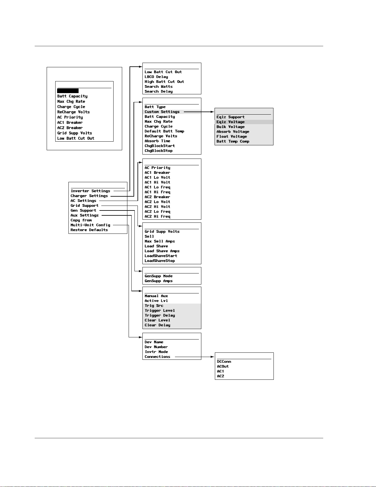
Basic Settings
XW6048 00:Basic
Batt Type
Advanced Settings
XW6048 00: Adv
[Flooded]
[440Ah]
[100%]
[2-Stage]
[50V]
[AC1]
[60A]
[60A]
[54V]
[44V]
[XW6048 01]
XW6048 00:Inv
XW6048 00:Chg
XW6048 00:AC
XW6048 00:Grid
XW6048 00:Gen
XW6048 00: Aux
[44V]
[10s]
[70V]
[50W]
[2s]
[Flooded]
[440Ah]
[100%]
[2-Stage]
[Warm]
[50V]
[180min]
[12:00AM]
[12:00AM]
[AC1]
[60A]
[106V]
[132V]
[55Hz]
[65Hz]
[60A]
[80V]
[138V]
[55Hz]
[65Hz]
[54V]
[Disabled]
[28A]
[Disabled]
[60A]
[12:00AM]
[12:00AM]
[Disabled]
[10A]
[ManualOff]
[ActHi]
[LowBattV]
[42V]
[1sec]
[48V]
[1sec]
Custom Settings
[Disabled]
[64.0V]
[57.6V]
[57.6V]
[54.0V]
[108mV/C]
“Custom Settings” is displayed
only when “Custom” is selected
under “Batt Type.”
“Eqlz Voltage” is displayed only
when “Eqlz Support” is Enabled.
Trigger and Clear settings are
displayed only when “Automatic” is
selected under “Manual Aux.”
Note: The System Control Panel
displays only four lines of the
configuration menus at one time.
To view additional settings, press
the down arrow button.
Figure 3-3
Basic and Advanced Settings
XW6048 00: Multi
[XW6048]
[SplitPhMstr]
[00]
Connections
[HouseBatt1]
[ACLoad1]
[Grid1]
[Gen1]
3–6 975-0240-01-01
Page 45

Inverter Settings Menu
The Inverter Settings Menu contains settings that control when the XW Inverter/
Charger turns on and off when it is inverting.
Inverter Settings Menu
Table 3-2
Item Description
Low Batt
Cut Out
LBCO
Delay
High Batt
Cut Out
Search
Watts
Search
Delay
Inverter Settings menu
This setting controls when the inverter turns off due to a low battery voltage
condition. The inverter will turn off only after this level has been reached
for the period of time set by the LCBO Delay. This setting is not
temperature compensated.
LBCO Delay controls how long the inverter is allowed to operate at or
below the Low Battery Cut Out level before turning off due to a low battery
voltage condition. The inverter will turn off only after the Low Batt Cut Out
level has been reached for this uninterrupted period of time.
Once the inverter has shut off, the battery voltage must rise 4 volts above
the Low Batt Cut Out setting for inverter operation to resume.
High Batt Cut Out sets the maximum battery voltage at which the inverter
will operate. If the battery voltage exceeds this limit for more than 1
minute, the inverter displays a fault message (F49) and shuts down. The
inverter will not support AC loads when in this condition. If a qualified AC
source is present, the unit passes AC through to the loads. The inverter
automatically restarts when the voltage drops to 3 volts (24-volt system) or
6 volts (48-volt system) below the High Batt Cut Out setting. If battery
voltage continues to rise after shutdown, an external charger may still be
charging the batteries. The XW Inverter/Charger cannot control how
external chargers operate.
Search Watts sets the inverter’s search sensitivity when Search mode is
enabled. When a load larger than this setting is present, the inverter turns
on. Enabling Search mode from the Setup Menu (see page 3–2) can
minimize power draw from the battery during periods of low demand from
loads. Also see “Using Search Mode” on page 3–8.
Search Delay sets the time between search pulses. When searching for
loads, the XW Inverter/Charger sends out search pulses to determine if a
load is present. If the XW Inverter/Charger finds a load above the Search
Watts setting, the inverter comes on. XW Inverter/Charger power draw
while in Search mode decreases when Search Delay is increased, but the
inverter’s response time to active loads is reduced.
For default settings, see “Inverter Menu” on page B–3.
Using the Low Battery Cut Out and LBCO Delay Settings
The Low Batt Cut Out setting is the lowest voltage level acceptable for battery use
by the inverter. When the batteries dischar ge to the Low Batt Cut Out setting, and
are held at or below this level for the LBCO Delay time, the inverter output shuts
down and transfers any available AC source (generator or grid) to the charger to
975-0240-01-01 3–7
Page 46

Configuration
Using Search Mode
Why use Search
mode?
When to set up
Search mode
bring the battery level back above the Low Batt Cut Out setting. After shutdown,
the inverter does not support any AC loads, and AC loads must be powered by
either a generator or grid power.
If using an automatic generator starting system, it is recommended to set the AGS
voltage trigger setting higher than the XW Inverter/Charger Low Batt Cut Out
voltage. Otherwise, inverter output turns off and then back on when the generator
auto-starts.
If using an automatic generator starting system with the start trigger set to the
same voltage as the LBCO voltage, do not set the LBCO Delay for less than the
amount of time it takes the generator to start and connect. Otherwise, inverter
output turns off and then back on when the generator auto-starts.
While idling in Search mode, the inverter sends out an electrical search pulse that
travels through the AC wiring “looking” for connected loads. The frequency of
the search pulse is set using the Search Delay setting.
After a load larger than the Search Watts setting is detected, the inverter turns on.
Search mode allows you to selectively power only items that draw more than a
certain amount of power, which can result in power savings.
The XW Inverter/Charger has a no-load power draw of about 28 watts. Enabling
Search mode reduces this power draw to less than 8 watts.
The Search mode feature on the inv erte r is only valuable if the inverter can spend
a fair amount of time “sleeping” each day. Therefore, if Search mode is to be
utilized it must be adjusted properly . The initial adjustment should be made so that
the inverter comes on only when needed.
Certain types of loads can cause Search mode not to work as expected. These
types of loads are described on page 4–3 of the Troubleshooting chapter. If these
kinds of loads are in the system, follow the suggestions given to eliminate the
problem. Some televisions with instant-on circuits have a menu or control to
disable it. If clocks are the problem load, consider using battery-powered units.
If the problem loads cannot be eliminated, there are two work-around solutions:
1. Disable Search Mode from the main XW Inverter/Charger Setup menu,
causing the inverter to always remain at full output voltage.
2. Use a search-friendly “companion load” whose only purpose is to be switched
on to “wake up” the inverter to power the load that is unable to bring the
inverter out of Search mode.
Important:
Chargers. The combined current draw of multiple inverter/chargers falsely brings the units
out of Search mode. Search Mode should be disabled on the Setup menu of each XW
Inverter/Charger.
3–8 975-0240-01-01
Search mode does not function in installations with multiple XW Inverter/
Page 47

Inverter Settings Menu
Notes:
• Search mode, by function, cannot work with clocks and timers or devices that need
power 24 hours a day. Examples of devices with timers include video recorders,
coffee makers with brew timers, refrigerators, and freezers with defrost timers.
Examples of devices that need power 24 hours a day include telephone answering
machines, alarm systems, motion detection lights, and some thermostats.
• When the inverter is searching the output for loads, lights that have a wattage lower
than this setting may flash momentarily.
975-0240-01-01 3–9
Page 48

Configuration
Charger Settings Menu
The Charger Settings menu gives you options for configuring the XW Inverter/
Charger to operate from your battery bank.
Table 3-3
Item Description
Batt Type Batt Type selects the system battery chemistry and type: Flooded
Custom Settings Displays the Custom Battery Settings menu, where you can adjust
Batt Capacity Selects the system battery capacity in amp-hours.
Max Chg Rate Sets the percentage of the maximum DC output current that is
Charge Cycle Sets the charging method: 3-Stage (Bulk, Absorption, Float) and 2-
Default Batt
Temp
ReCharge Volts Sets the battery voltage level at which a new charge cycle begins.
Absorb Time Sets the time spent in the Absorption stage, before transitioning to
Chg Block Start Sets the time to halt charging on AC1 (Grid). The AC2 (Gen) port is
Chg Block Stop Sets the time that charging on AC1 can resume. At the Chg Block
Charger menu items
(default), AGM, Gel and Custom.
Selecting Custom displays the Custom Settings item, which allows
you to adjust the settings for each charging stage.
settings specific to your battery type and installation.
The Custom Settings item is displayed only after “Custom” is
selected under Batt Type.
available to the charger. The maximum DC output current for
different models is:
• XW4024—150 Adc
• XW4548—85 Adc
• XW6048—100 Adc.
Stage (Bulk, Absorption, NoFloat).
Selects the battery temperature charging compensation if a battery
temperature sensor is not installed. In the absence of a battery
temperature sensor, the charger uses one of three settings: “Cool”
(5 °C), “Warm” (25 °C), or “Hot” (40 °C).
Float or NoFloat.
unaffected by the Charger Block settings. The Charger Block Start
and Stop settings allow you to select when the charger stops charging
on AC1.
To disable the Charger Block function, set Chg Block Start and Chg
Block Stop to the same time. See “Using Charger Block” on page 3–
14.
Stop time, charging on AC1 is enabled again.
For default settings, see “Charger Menu” on page B–3.
3–10 975-0240-01-01
Page 49
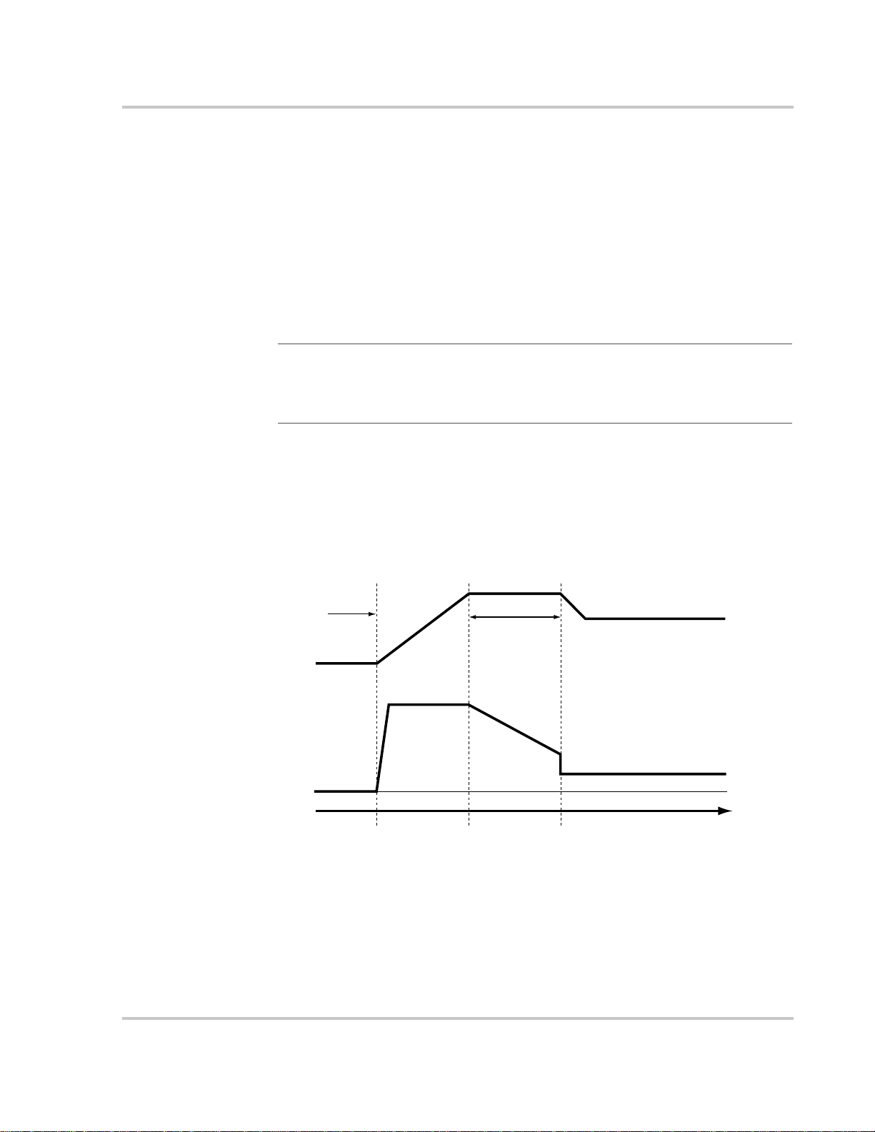
Battery Charger Functions
When AC power is available, the XW Inverter/Charger can operate as a battery
charger . Dif ferent battery types and chemistries require dif ferent charging voltage
levels. Not charging batteries at the required levels can shorten battery life or
possibly damage them. The XW Inverter/Charger is configured at the factory to
work with the battery types recommended for inverter applications. If the default
settings do not work for your specific installation, you can adjust the charge stage
settings (as recommended by the battery manufacturer) on the Custom Battery
Settings menu (see page 3–15). It will be necessary to select the voltage levels
required and to set the voltage limits for the various stages of charging.
Note: This information is provided for guidance only. Variations in battery chemist ry
and site-specific environmental considerations mean that you should consult your system
designer or battery manufacturer for specific recommendations for appropriate battery
voltage and current settings.
Multi-Stage Charging Process
The charging cycle uses a multi-stage charging process to maintain the batteries.
Whenever AC power that is within the range of the inverter’ s settings is present at
the inverter’s input, it passes power through to the connected load and begins
charging the batteries.
Charger Settings Menu
Bulk Stage Absorption Stage Float Stage
Charging
Started
DC Voltage
DC Current
Time
Figure 3-4
Increased Voltage
Max Charge Rate
Setting
Constant Current Reduced Current
Three-Stage Battery Charging Cycle
Bulk/Absorption
Volts Setting
Absorption Time
Constant Voltage
Float Volts Setting
Reduced Voltage
Reduced Current
Bulk Stage Bulk charge is the first stage in the charging process and provides the batteries
with a controlled, constant current. Once the battery voltage rises to the bulk
voltage threshold, the charger switches to the Absorption stage.
975-0240-01-01 3–11
Page 50

Configuration
Absorption Stage Absorption charge is the second stage of battery charging and provides the
batteries a controlled, constant voltage. During this stage, the current supplied to
the batteries slowly decreases. When this current falls below 2% of the battery
capacity, or when the configurable Absorb Time expires, the charger switches to
the Float or NoFloat stage, depending on the selected charge cycle.
Note: If there are DC loads on the batteries, the charger’s current may never decrease
to a level to initiate the next stage of charging. In this case, the charger would stay in
absorption until the Absorb Time setting is reached.
T o ensure the char ger does not remain in absorption for too long, adjust Absorb Time on
the Charger Settings menu. The timer begins at the start of the absorption stage and
terminates absorption charging if the charge current does not decrease to below 2% of
the battery capacity before the Absorb Time setting expires. The Absorb Time setting
may be increased if the charge cycle continually runs the full Absorb Time in the
absence of DC loads. This is an indication of too large a battery bank for the selected
Absorb Time setting.
Float Stage Float charge maintains a trickle charge on the batteries whenever AC is present on
the inverter’s input. Float charging reduces battery gassing, minimizes watering
requirements (for flooded batteries), and ensures the batteries are in a constant
state of readiness. When three-stage charging is selected, the charger will
automatically switch to the float stage after the batteries have received a bulk and
absorption charge (see Figure 3-4 on page 3–11). The batteries will be maintained
at the default float voltage level for the selected battery type or the voltage
selected under Float Voltage on the Custom Battery Settings menu.
Note: The battery voltage can increase above the float voltage when using an external
charging device such as PV arrays, wind turbines, and micro-hydro generators. Be sure
to include appropriate charge management equipment with all external DC sources.
2-Stage 2-Stage (or No Float) mode differs from an ordinary three-stage charge mode in
that it does not continuously maintain the battery at float voltage. Instead, the XW
Inverter/Charger begins charging the battery in bulk mode whenever the battery
voltage drops below the recharge level. While the battery voltage is above the
recharge level the inverter’s AC transfer switch continues to pass power through
from the utility grid to the loads, but does not actively charge the batteries. 2Stage mode increases efficiency of utility connected systems by reducing the
amount of power consumed by the inverter and batteries compared to when the
battery is continuously maintained at Float voltage. This feature can extend the
life of most batteries.
To allow Grid Support and Sell Mode to function after battery charging has
completed, it is recommended to set the Charge Cycle to 2-Stage.
Note: If the AC input fails or drops below the lower V ac limit (as set in “AC Settings”),
the complete multi-stage charge cycle (Bulk, Absorption, Float/No Float) restarts once
the source AC returns to an in-tolerance condition. If the batteries are already nearly full,
the charge cycle will take little time to complete.
3–12 975-0240-01-01
Page 51

Charging
Started
DC Voltage
Charger Settings Menu
Bulk Stage Absorption Stage NoFloat Stage
Bulk/Absorption
Volts Setting
Absorption Time
Increased Voltage
Max Charge Rate
Setting
Constant Voltage
Exit Current Threshold
ReCharge Voltage
DC Current
Time
Figure 3-5
2-Stage Charging Cycle
Equalize Charging the Batteries
Many battery manufacturers recommend periodic equalize charging to level out
the voltage between individual cells, improving battery performance and lifespan.
Over time, the battery’s electrolyte can become “stratified,” causing inactive areas
in the plate material. If this condition is allowed to continue for extended periods,
the battery plates can “sulfate” and become unusable. Equalizing the batteries is a
controlled overcharging method that mixes up the electrolyte and reactivates the
unused areas of the plate material, restoring batteries to a full state of charge.
Consult the battery manufacturer’s recommendation for equalize charging
settings.
To start equalizing the batteries:
u On the XW Setup menu, highlight Equalize and select Enable.
Or
Press the equalize button on the Inverter Information Panel for five seconds.
Constant Current Reduced Current
NoFloat Stage
WARNING: Explosion hazard
Only flooded or vented batteries should be equalize charged. Hydrogen and oxygen gases
are produced when batteries are equalize charged. Provide adequate ventilation and
remove all sources of ignition to prevent explosion.
Important:
(such as a system including multiple XW Inverter/Chargers and Solar Charge Controllers),
there is no system-wide equalization command for all devices. To equalize with multiple
devices, each would have to be enabled individually. Alternatively, equalization can be
performed using only one device. During the equalization process, one device applies the
equalization charge while the other devices continue to operate in synchronized charge
mode, typically in float (three-stage charging) or no-float (two-stage charging).
975-0240-01-01 3–13
In a system where more than one device is capable of equalizing batteries
Page 52

Configuration
Using Charger Block
The Charger Block feature halts charging on AC1 (Grid) for a period of time each
day. This period of time is defined by the Chg Block Start and Chg Block Stop
settings. In areas where the utility charges variable rates for electricity, it is
preferable to use utility power for charging only during non-peak hours. Charger
Block can prevent utility power from being used for battery charging during peak
billing periods.
During the time period set between Chg Block Start and Chg Block Stop, AC1
(Grid) input continues to be passed through to the loads. Inverter operation
remains unaffected during the charger block period.
During the Charger Block period, no char gi ng on AC1 occurs even if the batteries
discharge below ReCharge Volts setting. However, a generator connected to AC2
(in the absence of utility/AC1 power) or an XW Solar Charge Controller may
charge batteries during the Charger Block period. AC priority must be set to AC2
to charge batteries with a generator connected to AC2 during the Charger Block
period.
If the charger is operating (that is, in Float, Absorption, Bulk or Equalize stage) at
the Chg Block Start time, charging on AC1 stops immediately and the charger
enters an idle state identical to No Float (see “2-Stage” on page 3–12). When the
Charger Block period is over, the charger does not resume the charge stage that
Chg Block Start interrupted. Instead, if the batteries are above the ReCharge Volts
setting, the charger remains idle.
If the batteries have fallen to the ReCharge Volts setting during the Charger Block
period, the XW Inverter/Charger begins a new charge cycle with the Bulk stage
after the Charger Block period has expired (at the Chg Block Stop time).
For example, Charger Block is set to start at 5:00 PM and end at 8:00 PM. If the
XW Inverter/Charger is charging from AC1, charging stops at 5:00. When
Charger Block ends at 8:00, the XW Inverter/Charger does not automatically
resume charging. The unit first measures the battery voltage. If the voltage is
below the ReCharge Volts setting, then the XW Inverter/Charger starts a new
charge cycle from Bulk. If the battery voltage is above the ReCharge Volts setting,
the XW Inverter/Charger remains idle and continues passing through AC to the
loads. The XW Inverter/Charger also keeps measuring the battery voltage as
before to determine whether to start a new charge cycle.
3–14 975-0240-01-01
Page 53

Custom Battery Settings Menu
CAUTION: Equipment damage
T o avoid damaging your batteries during charging or equalization, consult your battery
manufacturer and associated documentation before setting a custom battery type.
The Custom Settings menu can be selected after “Custom” is selected under Batt
Type.
The Custom Settings menu allows you to adjust chargi ng and equalization voltage
for batteries with specifications that fall outside the default settings for the battery
types the XW Inverter/Charger offers.
You can also adjust the temperature compensation constant for the Battery
Temperature Sensor on the Custom Battery menu.
Charger Settings Menu
Important:
settings for a Flooded battery type.
All settings for configuring a custom battery type are based on the default
Table 3-4 describes the options available on the Custom Battery menu.
Table 3-4
Item Description
Eqlz Support Enables or disables the ability to enter an equalization cycle. Refer to
Eqlz Voltage
Bulk Voltage Sets the bulk voltage for a custom battery type.
Absorb Voltage Sets the absorption voltage for a custom battery type.
Float Voltage Sets the float voltage for a custom battery type.
Batt Temp
Comp
a.The Eqlz Voltage setting is displayed when Eqlz Supp ort is set to On.
Custom Battery Settings menu items
the battery manufacturer’s specifications to determine whether
equalization is recommended.
a
Selects the equalization voltage. Consult your battery manufacturer
for equalization voltage setting.
Battery temperature compensation for a custom battery type. This
setting is the reference that the BTS uses to adjust the charging
voltage when the temperature falls above or below 25 °C.
For default settings, see “Custom Battery Menu” on page B–4.
975-0240-01-01 3–15
Page 54

Configuration
AC Settings
The AC Settings menu configures the voltage and frequency limits for AC line 1
(grid) and AC line 2 (generator). These are the limits at which the XW Inverter/
Charger considers input voltage qualified—that is, suitable for charging batteries
or powering loads. If the input voltage is not qualified according to these settings,
the XW Inverter/Charger transfers from using AC input to inverting.
Table 3-5
Item Description
AC Priority Sets the priority for the AC source (AC1 or AC2) for qualification and
AC1 Breaker Sets the AC1 (Grid) breaker size, based on the size of the breaker
AC1 Lo Volt Minimum acceptable input voltage level from the utility grid.
AC1 Hi Volt Maximum acceptable input voltage level from the utility grid.
AC1 Lo Freq Minimum acceptable utility grid input frequency.
AC1 Hi Freq Maximum acceptab le utility grid input frequency.
AC2 Breaker Sets the AC2 (Gen) breaker size, based on the size of the installed AC
AC2 Lo Volt Minimum acceptable input voltage level from the generator.
AC2 Hi Volt Maximum acceptable input voltage level from the generator.
AC2 Lo Freq Minimum acceptable generator input frequency.
AC2 Hi Freq Maximum acceptable generator input frequency.
AC Settings menu
transfer. For example, this setting allows the XW Inverter/Charger to use
a renewable energy source (such as an AC hydro generator) connected to
AC2 on a first-priority basis and use utility power only when renewable
energy is insufficient or unavailable to power loads.
In systems that use both utility grid (AC1) and generator (AC2) input,
AC Priority is recommended to be set to AC2. Assuming the generat or is
intended for occasional use only, the XW Inverter/Charger will use
utility power until the generator is started.
installed on AC1. The installed breaker size must not exceed the
capacity of the upstream distribution panel. The XW Inverter/Charger
limits the maximum input current to this setting by derating its charging
current. If the connected loads exceed the AC1 breaker setting, the AC
breaker trips (causing fault F63, F64, or F65). The breaker may not trip
if Grid Support is enabled and battery voltage is above the Grid Support
Volts setting, or if Peak Load Shave is enabled and the Load Shave Time
window is active.
breaker. The breaker size must not exceed the capacity of the generator.
The XW Inverter/Charger limits the maximum input current to this
setting by derating its charging current. If the connected loads exceed
the AC2 breaker setting, the AC breaker trips (causing fault F63, F64, or
F65). The breaker may not trip if Grid Support is enabled and battery
voltage is above the Grid Support V olts setting, or if Peak Load Shave is
enabled and the Load Shave Time window is active.
For default settings, see “AC Menu” on page B–4.
3–16 975-0240-01-01
Page 55

Grid Support Settings
The Grid Support Settings menu contains configuration options for grid-tie
operation. To enable all these settings, Grid Support must be enabled in the Setup
menu (see “XW Inverter/Charger Setup Menu” on page 3–2).
Grid Support Settings
Important:
is recommended to set the Charge Cycle to 2-Stage. After completing the absorption
charger stage the XW Inverter/Charger checks whether battery voltage is above the Grid
Supp Volts setting. If battery voltage is above the Grid Supp Volts setting, the XW
Inverter/Charger uses available DC power to support the loads. See “Charger Settings
Menu” on page 3–10.
Turning the charger off also enables Grid Support functionality.
If the Charge Cycle is set to 3-Stage, the Grid Supp Volts setti ng must be higher than the
float voltage setting for your battery type for Grid Support settings to function (see
“Custom Battery Menu” on page B–4 for default Float voltag e setting s).
Important:
functions for five minutes. During this five-minute period the XW Inverter/Charger
determines whether the utility grid voltage and frequency are stable and within nominal
range. For more information, see “Islanding Protection” on page 1–5.
Table 3-6
Item Description
Grid Supp Volts Sets the level to which the batteries will be discharged when the
Sell Turns Sell mode on and off. When Sell is enabled, the XW
Max Sell Amps Sets the maximum AC amps allowed to be delivered to the utility
Load Shave Enables or disables the Load Shave feature. Load Shave allows the
To allow Grid Support to function after battery charging has completed, it
Upon startup, the XW Inverter/Charger does not enable Grid Support
Grid Support Settings menu
inverter is selling power to the grid or supporting the power grid by
providing additional power to the loads. This setting is not
adjusted for the battery temperature if the temperature sensor is
installed.
Inverter/Charger AC output is divided between powering loads
and delivering power to the utility grid. Sell mode requires the
battery voltage to be above the Grid Supp Volts.
grid from a solar array and/or the batteries during grid-tie
operation. This setting is only used if Sell mode is enabled.
The Max Sell Amps must be less than 80 per cent of the selected
AC1 breaker setting. If set higher, the breaker setting will override
the Max Sell Amps setting to avoid tripping the breaker.
XW Inverter/Charger to support the grid in powering local loads
during a defined window of time (set using Load Shave Start and
Load Shave Stop). When in this mode, the XW Inverter/Charger
operates until the batteries discharge to the LBCO threshold, after
which the unit reverts to AC pass-through. The charger is
automatically blocked during the Load Shave time window.
975-0240-01-01 3–17
Page 56

Configuration
Table 3-6
Item Description
Load Shave Amps Sets the maximum amount of current that can be drawn from the
Load Shave Start Sets the time of day that the Load Shave feature operates. This
Load Shave Stop Sets the time of day that the Load Shave feature stops operating. If
For default settings, see “Grid Support Menu” on page B–5.
Energy Management
The XW Inverter/Charger can be programmed to control how and when to us e
utility power. Advanced features allow management of peak loads and time-ofuse billing.
Grid Support Settings menu
AC1 (grid) input by the loads and battery charger combined. This
setting determines the amperage level at which the inverter starts
drawing power from the batteries to add to the utility power to
meet the demand of the loads.
Typically, this value is set to the size of the AC circuit breakers
feeding the inverter’s AC input.
feature is suited for regions where local utilities impose peak usage
surcharges. The inverter provides load shaving power as long as
battery voltage is above the Low Batt Cut Out setting.
Load Shave is enabled and Load Shave Start and Load Shave S t op
are set to the same time, the XW Inverter/Charger load shaves
continuously.
Charger Block
Grid Support
See “Using Charger Block” on page 3–14.
The Grid Support feature allows the XW Inverter/Charger to support local loads
by converting excess capacity from external DC sources connected to its battery
bank. Examples of external DC sources are charge controllers, micro-hydro, and
wind turbines.
For Grid Support to function, Grid Support must be enabled on the Setup menu
and the battery voltage must be above the Grid Supp Volts setting.
There are two modes of operation within Grid Support.
Grid Support enabled, Sell disabled In this mode, available excess DC power
is converted and used to power local loads. No power is exported to the utility. If
the local load demand exceeds the available power from the external DC sources,
power is then drawn from the utility to support the load. However, if the local load
demand is less than the power available from external DC sources, the net excess
power from the external DC sources is not converted and hence not used.
3–18 975-0240-01-01
Page 57

Peak Load Shaving
Grid Support Settings
Grid support enabled, Sell enabled In this mode all available excess DC
power is first used to power local loads, and any excess is exported to the utility
grid.
Note: Running and Start-up (Peak) currents are limited to the maximum current limits
of the inverter.
Many utilities impose a surcharge on their customers based on the peak load used
by a facility. To reduce utility peak demand charges, the inverter can be
configured (using the Load Shave Amps setting) to limit the maximum draw the
AC loads place on the utility. The inverter can be programmed to provide power
above a specified level, eliminating the surcharge. When the utility current draw
reaches the maximum level, the inverter assists by providing battery powered AC
to the loads.
For Peak Load Shaving to be effective, all loads must be connected to the inverter.
For large loads, multiple (or stacked) inverters may be required.
To further ensure the batteries are able to supplement the power requirements of
the connected load, an additional source of power (solar, wind or hydroelectric) is
recommended.
Peak Load Shaving can also be used in addition to the time-of-use metering.
Time-of-Use Metering
Utilities use time-of-use metering to determine utility charges during peak usage
hours and to impose a surcharge. The XW Inverter/Charger can be configured
(using the Load Shave Start, Load Shave Stop and Charger Block settings) to
overcome these peak charges by using utility power to charge the battery bank
during the inexpensive energy hours and consuming the battery energy during
expensive energy hours.
For example, if Charger Block is set between 9:00 AM and 10:00 PM and Load
Shave is set between 6:00 PM and 9:00 PM, charging on AC1 stops at 9:00 AM
and continues to pass utility AC through to the loads. If charging is required
during the charger block period, and AC Priority is set to AC2, the XW Inverter/
Charger can use any AC source connected to AC2. Loads will transfer to the AC
source on AC2 as well. The inverter connects to the utility grid at 6:00 PM and
supports loads using the batteries. The inverter continues to run until 9:00 PM.
The XW Inverter/Charger then stops supporting the utility grid and passes utility
AC through to the loads. At 10:00 PM utility AC begins maintaining the batteries
based on the battery charger settings.
The above example allows an external renewable energy source to be utilized as a
primary charging source during a desired time window. The charger (using utility
AC connected to AC1) can then be used to supplement the battery charging when
the rates utility rates are low.
975-0240-01-01 3–19
Page 58

Configuration
When using the system for time-of-use metering, the system should be designed
with a battery capacity large enough to support loads during the entire peak rate
period without reaching the Low Battery Cut Out setting.
T o further ensure the batteries are able to support the loads, an additional source of
power (solar, wind or hydroelectric) is recommended. Depending upon the
capacity of the system, certain heavy loads should only be run during non-peak
periods.
Note: In the event the batteries reach their Low Battery Cut Out voltage, the inverter
will automatically reconnect to the utility grid to maintain the connected load.
3–20 975-0240-01-01
Page 59
Generator Support Settings
Generator support allows power to be automatically drawn from the batteries to
assist an AC generator to support heavy loads (loads that exceed the available
current from the generator).
Generators have a limited output current and it is possible to reach this limit when
operating heavy loads. The XW Inverter/Charger is designed to assist the
generator when heavy current demands load down the generator by supplying
additional power from the batteries.
In addition, the battery charger can back off its charging current to the batteries so
the combined load of the ch ar ger an d load su pport does not exceed the capacity of
the generator or trip its output breakers or fuses.
Note: Running and Start-up (Peak) currents are limited to the maximum current limits
of the inverter.
Generator Support Settings
Table 3-7
Setting Description
GenSupp Mode Turns the Generator Support feature on and off.
GenSupp Amps Sets the generator load level at which the XW Inverter/Charger
Gen Support Menu Values
For default settings, see “Gen Support Menu” on page B–5.
Auxiliary Output Settings
The Aux menu allows you to enable and configure the auxiliary output. The
auxiliary output provides 12 Vdc at 250 mA to power a relay, indicator light or
alarm.
Table 3-8
Setting Description
Manual Aux Sets the state of the Auxiliary Output. ManualOn or ManualOff allow
Active Lvl Sets the mode (polarity) of the aux output. When triggered, the output
Trigger Src Selects the desired condition (Trigger Source) to activate the Aux
Trigger Level Sets the voltage or temperature level (depending on the selected
Aux Menu Values
supplies power from the batteries to support the generator.
manual control of the Auxiliary Output. When set to Automatic, a
trigger source can then be selected.
can be active high (12 Vdc output turns on) or active low (output is
high until the trigger turns it off).
Output. The Trigger Source options are LowBattV, HighBattV,
LowBattTemp, HighBattTemp, and Fault.
trigger source) at which the aux output is activated. If the selected
Trigger Source is a Battery Voltage, the range also varies according to
the nominal battery voltage of your system.
975-0240-01-01 3–21
Page 60

Configuration
Table 3-8
Setting Description
Trigger Delay Sets a delay period between when the trigger occurs and when the aux
Clear Level Sets the voltage or temperature level (depending on the selected
Clear Delay Sets a delay period between when the Clear Level setting occurs and
Aux Menu Values
For default settings, see “Aux Menu” on page B–6.
Important:
output trigger is active, changing the trigger level will clear the trigger.
Trigger Source Descriptions
Low Batt Voltage Activates the Auxiliary Output when the battery voltage falls
below the Low Batt Voltage setting for the trigger delay time. The Auxiliary
Output turns off when the battery voltage rises above the Clear setting for the
Clear Delay time. Use this setting if you want the auxiliary output to control a
relay to disconnect loads from a battery that is nearly discharged, or to activate a
low-battery-voltage alarm such as a buzzer or light.
High Batt Voltage Activates the Auxiliary Output when the battery voltage
rises above the Hi Batt Voltage setting for the trigger delay time. The Auxiliary
Output turns off when the battery voltage falls below the Clear setting for the
Clear Delay time. This setting is useful for:
output is activated.
trigger source) at which the aux output becomes inactive.
when the aux output becomes inactive.
Changing the Trigger Level resets the auxiliary output. If an auxiliary
• Installations that have another external charging source such as a wind
generator or hydro generator connected directly to the batteries. The XW
Inverter/Charger Auxiliary Output can control a relay to disconnect the
external charging source from the battery when the battery is in danger of
being overcharged, or control a relay to turn on a diversion load.
• Activating a high-battery-voltage alarm such as a buzzer or light.
• Activating a vent fan to disperse hydrogen from the battery compartment
when the batteries reach their gassing voltage.
Low Batt Temp Activates the Auxiliary Output when the battery temperature
falls below the Low Batt Temp setting for the trigger delay time. The Auxiliary
Output turns off when the battery temperature rises above the Clear setting for the
Clear Delay time. Battery temperature is measured with a battery temperature
sensor. Do not use this setting if a battery temperat ure sensor is not installed. W ith
this setting, the auxiliary output can turn on an indicator alarm if the batteries are
too cold. A battery with frozen electrolyte will not accept a charge.
High Batt Temp Activates the Auxiliary Output when the battery temperature
rises above the Hi Batt Temp setting for the trigger delay time. The Auxiliary
Output turns off when the battery temperature falls below the Clear setting for the
3–22 975-0240-01-01
Page 61

Clear Delay time. Battery temperature is measured with a battery temperature
sensor. Do not use this setting if a battery temperat ure sensor is not installed. W ith
this setting, the auxiliary output can turn on a fan to cool the battery compartment.
Fault Activates the Auxiliary Output when a fault occurs. The Auxiliary Output
clears when the fault is cleared.
Multi-Unit Config Menu
The Multi-Unit Config menu configures the XW Inverter/Charger to operate as a
part of a multi-unit installation.
Multi-Unit Config Menu
Important:
Standby mode. When entering the Multi-Unit Config menu, the unit also identifies itself
by flashing all front panel lights. After exiting the Multi-Unit Config menu, the XW
Inverter/Charger returns to Operating mode and the front panel lights stop flashing.
Table 3-9
Item Description Default Range
Dev Name Allow s customization of the default device name. This setting
Dev Number Allows setting of a unique unit number in a multiple-unit
Inverter Mode For a multi-unit system to operate, one XW Inverter/Charger
Connections Select to display the Connections menu. See “Connections
Multi-Unit Config menu
is optional and does not affect operation. See “Setting the
Device Name” on page 3–24.
system. See “Setting the Device Number” on page 3–25.
must be configured to “SplitPhMaster” and the rest as
“SplitPhSlave,” otherwise a system-wide fault is asserted.
Modes for single-phase models will be added to future product
releases.
Menu” on page 3–26.
Accessing this menu automatically places the XW Inverter/Charger in
n/a n/a
00 00–31
SplitPhMaster For split-phase
models:
SplitPhMaster,
SplitPhSlave
n/a n/a
When installing a multi-unit system, each setting on the Multi-Unit Config menu
(except for “Dev Name”) must be configured for each XW Inverter/Charger in the
system. The Multi-Unit Config settings should be configured in the following
order:
• Dev Number
• Inverter Mode
• Connections.
975-0240-01-01 3–23
Page 62

Configuration
Setting the Device Name
The “Dev Name” setting allows you to customize the name of the XW Inverter/
Charger as it is displayed on other screens and menus.
The characters available are:
•A to Z
•a to z
•0 to 9
• space.
Note: Increasing the number of characters in a device name may cause other text on the
same line to run off the edge of the screen. Device names should be limited to 10
characters or less.
To customize the XW Inverter/Charger name:
1. On the device setup menu, select Advanced Settings.
If “Basic Settings” appears instead of “Advanced Settings” on the device
setup menu, display “Advanced Settings” by pressing Enter + Up arrow +
Down arrow at the same time.
2. Select the Multi-Unit Config menu.
3. Select Dev Name.
4. Press Enter.
The last letter of the XW Inverter/Charger name is highlighted.
5. Begin customizing the device name.
• To change the character, press the up or down arrow button. Holding
down the button causes the characters to scroll more quickly.
• To delete the character, press Exit.
• To add characters, press Enter.
6. When the correct character is shown, press Enter to select it.
7. After pressing Enter to select the last character of your customized device
name, press Enter again to return to the menu.
3–24 975-0240-01-01
Page 63
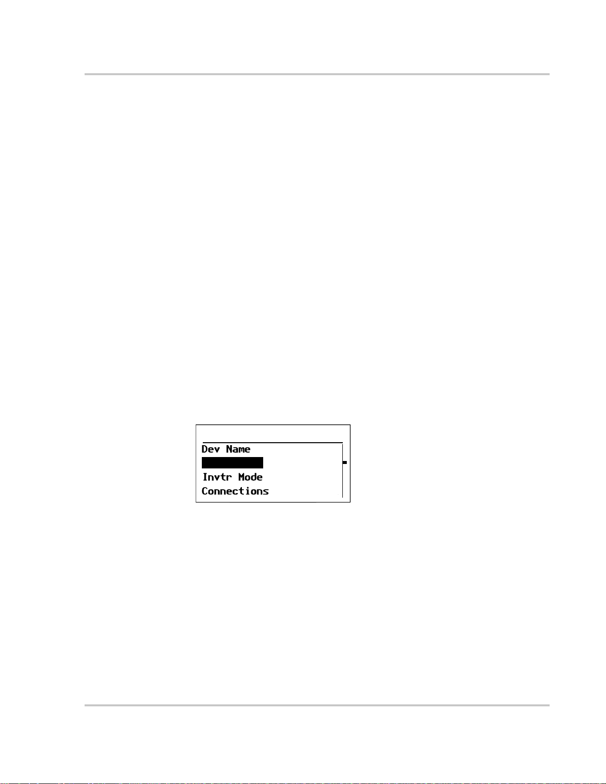
Setting the Device Number
Setting the device number gives a Xanbus-enabled device a unique identity when
several devices of the same type are installed in the networked power system.
When each identical device has a unique number, the System Control Panel can
correctly identify and display status information for each device.
A device number consists of two digits ranging from 00 (default) to 31.
If only one of each device is installed in the networked power system, you do not
need to set the device number. However , it is enc ouraged to set the device n umber
to a value other than 00. 00 is a factory default value and can be used to indicate a
“Restore Defaults” command was successfully performed if the value was
previously different.
To set the XW Inverter/Charger device number:
1. On the XW Inverter/Charger Setup menu, select Advanced Settings.
If “Basic Settings” appears instead of “Advanced Settings” on the Setup
menu, display “Advanced Settings” by pressing Enter + Up arrow + Down
arrow simultaneously.
On the Advanced Settings menu, select Multi-Unit Config and press Enter.
2. On the Multi-Unit Config menu, select Dev Number. See Figure 3-6.
3. Press Enter to highlight the instance number.
Multi-Unit Config Menu
4. Use the up and down arrow buttons to adjust the two-digit identifier number.
5. Press Enter.
XW6048 01:Multi
[XW1]
Dev Number
[01]
[SplitPhSlave]
Figure 3-6
Setting a Device Number
975-0240-01-01 3–25
Page 64

Configuration
Connections Menu
The Connections menu contains additional settings to allow the XW Inverter/
Charger to function as part of a multi-unit networked system.
Setting the connections for a Xanbus-enabled device provides a way of
identifying non-network connections for Xanbus-enabled devices (see Figure 3-7)
and enhancing networked power system mana gement. When connections are set,
devices of different types can detect that they share, for example, a common DC
input source, or a common grid or generator source.
In multi-unit networked systems, inverter/chargers can be stacked to produce
increased charge current. To achieve this functionality, the devices must be
configured to the same DC connection, such as House Battery Bank 1. The
inverter/chargers will collaborate on battery charging by listening to other units on
this shared DC connection.
Important:
System Control Panel, DC connections must be set to the same battery bank. If one of the
units is set with a different DC connection, a system configuration fault (F66) occurs.
Although the XW Power System does support multiple XW Inverter/Chargers connected
to multiple battery banks, such configurations cannot be set using the System Control
Panel. A special configuration application provided by Xantrex is required. To configure
such a system, contact your installer or Xantrex.
Table 3-10
Item Description
DCConn DC Input and Output connection. This is the common DC connection
ACOut AC Output connection. This connection specifies a common AC output
AC1 AC1 input connection. This connection specifies a common AC Line 1 input
AC2 AC2 input connection. This connection specifies a common AC Line 2 input
When configuring multiple networked XW Inverter/Chargers with the
Connections menu
between inverter/chargers, charge controllers, and Automatic Generator
Start.
connection between inverter/chargers. The AC Out connection has to be
configured so that the XW Inverter/Chargers know if they are connected to
the same load or not. If connected to the same load, select the same name on
all units; for example, “ACLoad1.” If connected to separate load banks, use
different names for the AC Out connection on each unit; for example,
“ACLoad1” on one unit and “ACLoad2” on the other.
for multiple inverter/chargers.
for multiple inverter/chargers.
For default settings, see “Connections Menu” on page B–6.
3–26 975-0240-01-01
Page 65

Connections Menu
AC1 Connection:
Select Grid 1 to 10, Gen 1 to 10
AC OUT AC IN AC IN
L1 N L2 L1 N L2 L1 N L2
AC
LOAD
AC Out Connection:
Select AC Load 1 to 10
Figure 3-7
XW Inverter/Charger Connections Representation
Operating Without Connections
AC1 and AC2 connections can be set to “None” if operating without a connection
to a specific power source. Only stand-alone devices (in a system that includes
only the device and an SCP) may be configured this way. Note that this is not a
necessary configuration step as the system will still operate with the default
settings. Using None where no AC source is used only serves as a label in this
case and does not modify the behavior of a unit.
GRID
(AC1)
GEN
(AC2)
AC2 Connection:
Select Grid 1 to 10, Gen 1 to 10
DC Connection:
Select House Battery 1 to 6
975-0240-01-01 3–27
Page 66

Configuration
Copying Settings From Another Unit
The “Copy from” command allows quick configuration of an XW Inverter/
Charger. After selecting another XW Inverter/Charger in the system to copy
settings from, common parameters are copied from the selected XW Inverter/
Charger to the XW Inverter/Charger being configured.
The following settings are copied from the selected unit:
• Inverter Settings
• Charger Settings
• AC Settings
• Grid Support Settings (except the Sell setting)
• Gen Support Settings.
The following settings are not copied between units:
• Inverter Mode
• Device Instance
• Device Name
• Auxiliary Output settings.
Resetting the XW Inverter/Charger to Default Settings
The Restore Defaults command returns the XW Inverter/Charger to factory
default settings. After using the Restore Defaults command, the XW Inverter/
Charger is no longer configured for the power system.
To restore XW Inverter/Charger default settings:
1. On the Advanced Setup menu, select Restore Defaults.
Warning W252 appears, asking to confirm the Restore Defaults command.
2. To cancel the command, press Exit. To continue with the Restore Defaults
command, press Enter.
Important:
brings up the Warning List, with warning W252 at the top. Press Enter to view W252 and
continue with the Restore Defaults process.
CAUTION: Equipment damage
Do not use the Restore Defaults command while the XW Inverter/Charger is operating.
De-energize the power system and disconnect the XW Inverter/Charger AC input before
using the Restore Defaults command. Reconfigure the XW Inverter/Charger before
reconnecting the AC input and re-energizing the power system.
If a warning is already active in the system, selecting Restore Defaults
3–28 975-0240-01-01
Page 67

4
Troubleshooting
Chapter 4, “Troubleshooting”, contains information and procedures
for solving possible problems with the XW Inverter/Charger.
Page 68

Troubleshooting
Troubleshooting Reference
This section provides you with troubleshooting tips to identify and solve most
problems that can occur with the XW Inverter/Charger.
This chapter is divided into the following sections:
1. “General Troubleshooting Guidelines” on page 4–2
2. “Inverter Applications” on page 4–3
3. “Inverter Troubleshooting” on page 4–5
4. “Battery Charger Troubleshooting” on page 4–8
5. “Faults and Warnings” on page 4–10
General Troubleshooting Guidelines
This section will help you narrow down the source of any problem you may
encounter. Please read the following troubleshooting steps:
1. Check for a W arning or Fault message on the System Control Panel or a Fault
code on the inverter information panel. If a message is displayed, record it
immediately.
2. As soon as possible, record on the form, “Information About Your System” on
page WA–4, the conditions at the time the problem occurred. These details
should include the following as well as any other information asked for on
page page WA–4:
• Loads the XW Inverter/Charger was running or attempting to run
• Battery condition at the time of failure (voltage or battery level, for
example), if known
• Recent sequence of events (for example, charging had just finished, utility
grid had failed but the inverter didn’t come on)
• Any known unusual AC input factors such as low voltage or unstable
generator output
• Extreme conditions which may have existed at the time (temperature or
moisture, for example).
3. Attempt the solution indicated in Table 4-2 on page 4–11 or Table 4-5 on
page 4–18.
4. If your inverter information panel or System Control Panel is not displaying a
Fault light, check the following list to make sure that the present state of the
installation allows proper operation of the unit. See also “Inverter
Troubleshooting” on page 4–5 and “Battery Charger Troubleshooting” on
page 4–8.
p Is the inverter/charger located in a clean, dry, adequately ventilated place?
p Have the AC input breakers opened? If so, your pass-through load may have
exceeded the rating of one or more of the input breakers.
4–2 975-0240-01-01
Page 69

p Are the battery cables adequately sized and short enough? See the XW Power
System Installation Guide for more information.
p Is the battery in good condition and are all DC connections tight?
p Are the AC input and output connections and wiring in good condition?
p Are the configuration settings correct for your particular installation?
p Are the display panel and the communications cable properly connected and
undamaged?
p Is the battery temperature sensor and its cable properly connected and
undamaged?
5. Contact Xantrex Customer Service for further assistance. Please be prepared
to describe details of your system installation and provide the model and
serial number of the unit. See page WA–1 for contact information.
Inverter Applications
The XW Inverter/Charger performs differently depending on the AC loads
connected to it. If you are having problems with any of your loads, read this
section.
Inverter Applications
Resistive Loads
Motor Loads
These are the loads that the inverter finds the simplest and most efficient to drive.
Voltage and current are in phase, which means they are in step with one another.
Resistive loads usually generate heat in order to accomplish their tasks. Toasters,
coffee pots, and incandescent lights are typical resistive loads. It is usually
impractical to run larger resistive loads—such as electric stoves and water
heaters—from an inverter due to their high current requirements. Even though the
inverter may be able to accommodate the load, the size of battery bank required
would be impractical if the load is to be run for long periods.
Induction motors (motors without brushes) require two to six times their running
current on start up. The most demanding are those that start under load (for
example, compressors and pumps). Of the capacitor start motors (typical in drill
presses and band saws, for example), the largest you can expect to run is 1 hp.
Universal motors are generally easier to start. Check that the Locked Rotor Amps
(LRA) rating of the motor load does not exceed the maximum surge current rating
of the inverter. Since motor characteristics vary, only testing will determine
whether a specific load can be started and how long it can be run.
If a motor fails to start within a few seconds or loses power after running for a
time, it should be turned off. When the inverter attempts to start a load that is
greater than it can handle, the inverter may shut down from an AC Overload fault.
975-0240-01-01 4–3
Page 70

Troubleshooting
Problem Loads
Very Small Loads
If the power consumed by a device is less than the threshold of the Search mode
circuitry, and Search mode is enabled, the inverter will not run. Most likely the
solution will be to disable the Search mode feature or lower the sense threshold.
Refer to Xantrex Tech Note TN 003 (“Making Sense of Search Mode”) for more
information.
Fluorescent Lights and Power Supplies
Some devices cannot be detected when scanned by Search mode circuitry. Small
fluorescent lights are the most common example. Some computers and
sophisticated electronics have power supplies that do not present a load until line
voltage is available. When this occurs, each unit waits for the other to begin. To
drive these loads, either a small companion load like a light bulb rated for more
than the Search Watts setting must be used to bring the inverter out of Search
mode, or the inverter may be programmed to remain on by disabling the Search
feature. (See “Using Search Mode” on page 3–8.)
Clocks
Searching
You may notice that your clocks may not be accurate. Some of the clocks on your
appliances may reset when the inverter/charger is in Search mode.
When the inverter is in Search mode, it may fail to start some loads even though
the rated wattage on the load is more than the Search Watts setting. Apply an
additional load (companion load) to make the inverter exit Search mode.
4–4 975-0240-01-01
Page 71

Inverter Troubleshooting
To determine the cause of an inverter error condition, refer to the troubleshooting
solutions below to resolve the situation.
Problem Possible cause Solution
Inverter Troubleshooting
Unit will not come on
(no LEDs are on) and
the inverter information
panel is blank or off.
Unit comes on, but goes
off quickly (several
attempts made).
No AC power output.
INVERT LED is on,
with no Fault/Warning
LED.
Unit was turned off using On/Off button
on front panel.
DC voltage on the inverter’s DC
terminals is incorrect.
Excessive load on output.
Unit is in over-temperature protection
and needs to cool down.
Remote Power Off signal is present.
Open AC output breakers or fuses and
bad output wire connections.
Turn the unit on again.
Check the battery voltage, fuses or breakers
and DC cable connections to the inverter. If
the DC voltage on the inverter’s DC
terminals is correct, have unit serviced.
Reduce loads.
Turn inverter off and allow the unit to cool
and increase ventilation.
Release or reset the Remote Power Off
switch.
Check the Load VAC status on the System
Control Panel Meters screen and check AC
voltage on the inverter AC Out terminal
block.
If the Meters screen shows correct AC
voltage but there is no AC voltage on the
inverter AC Out terminal block, check for
loose connections on the inverter terminal
block. If connections are not loose, the
inverter may need to be serviced.
If there is correct AC voltage on the Meters
screen and on the inverter AC terminal block,
check for open AC output breakers or fuses
and bad output wire connections.
If AC voltage on the Meters screen or
inverter AC terminal block is incorrect, have
unit serviced.
No AC power output.
INVERT LED is
flashing.
975-0240-01-01 4–5
AC load too small for Search Mode
circuit to detect.
Reduce Search Watts setting, increase load
above Search Watts setting, or turn off
Search Mode on the Setup menu.
If the AC1 LED is on, check inverter output
connections and voltage.
Page 72

Troubleshooting
Problem Possible cause Solution
Low AC power output
or low surge power.
INVERT LED is on.
AC inductive loads are
not running at full speed.
Inverter turns on and
then off or doesn’t turn
on at all.
Insufficient DC current being provided
to the inverter to operate the AC loads.
Search Watts setting is too low or high.
Potential problem loads for Search
Mode:
• Incandescent lights have a higher
starting wattage when the filament is
cold than the continuous rating of the
bulb.
• Fluor escent bulbs work the opposite
of incandescent light bulbs. If the
inverter is set to detect a 30-watt load
and a 40-watt fluorescent is switched
on, the inverter will not detect it,
This is because the fluorescent tube
is less than 30 watts until the gas in
the tube ionizes.
• Other loads: Some appliances draw
power even when turned off: TVs
with instant-on circuits, microwaves
with digital clocks, VCRs, and
clocks.
Check the battery voltage, fuses or breakers
and cable connections.
Ensure the battery bank is sufficient (check
for low DC voltage while running the load).
Ensure the cable length and size is correct
(see Installation Guide for correct cable). T ie
the battery cables together to reduce
inductance.
If the search sensitivity is set higher than the
combined loads, then an auxiliary load must
be used to bring the inverter out of Search
Mode before the appliances can be turned on.
If the sensitivity is set lower than the
combination of the loads, the loads will
remain on and excess battery drain will occur
since the inverter won’t ever “idle.”
One solution is to turn the item off at the
wall, use an extension cord with a rocker
switch, a switch at the outlet, or an
appropriate circuit breaker.
4–6 975-0240-01-01
Page 73

Problem Possible cause Solution
Inverter Troubleshooting
In a grid-interactive
mode, the unit is
experiencing excessive
anti-islanding faults. The
utility grid is not
dropping out, yet the
unit is disconnecting
from the grid.
The unit has two sets of AC limits:
adjustable AC qualification limits (as set
on the AC Settings menu), and nonadjustable anti-islanding limits which
are required to have a 5-minute
reconnect delay before returning to gridinteractive mode (Sell Mode or Grid
Support).
While in Sell Mode and in Grid Support,
these two sets of limits are both active.
Whichever limits are set to more
restrictive values (the narrower voltage
and frequency windows) will trip first
when the utility grid varies from normal
values.
If the AC qualification limits are set
outside the fast anti-islanding limits (see
F27, F30, F37 and F40), the unit will
experience less frequent disconnects
from the utility, but when it does
disconnect there will be a 5-minute
delay (minimum) before re-entering a
grid-interactive mode. During this 5minute delay, all other modes of
operation will be available, assuming the
grid re-enters the user-set frequency and
voltage limits (see “AC Settings” on
page 3–16).
Adjust the AC1 voltage and frequency
settings (see “AC Settings” on page 3–16).
Raise the high voltage and frequency
settings, and lower the low voltage and
frequency settings.
If the AC qualification limits are set
inside the anti-islanding limits, then the
unit will experience more frequent
disconnects from the utility, but when it
does disconnect there will not be a 5
minute delay before entering a gridinteractive mode, assuming the grid reenters the user-set frequency and voltage
qualification limits.
The impedance of the utility grid is too
high for the power being sold to the grid.
The utility grid impedance may be on
the high end if the installation is too far
from the utility sub station.
975-0240-01-01 4–7
Reduce the Max sell current until unit
disconnecting.
Page 74

Troubleshooting
Battery Charger Troubleshooting
To determine the cause of an charger error condition, refer to the troubleshooting
solutions below to resolve the situation.
Problem Possible Cause Solution
AC1/AC2 LED is on,
but will not start
charging
(allow 40 seconds to
synchronize).
AC1 or AC2 LED is
flashing, but will not
start charging
(allow 40 seconds to
synchronize).
1) Charger is disabled on the Setup menu.
2) Charger Block is enabled and the XW
Inverter/Charger is insid e of the Ch arger
Block time window.
3) The XW Inverter/Charger is load
shaving.
4) Charger is set for 2-stage charging and
has completed a full charge cycle.
5) Battery voltage is low and AC voltage
is high; in this case XW is a passive
rectifier charger. For an active charger
operation the following condition should
be met: battery voltage > [0.16 × Vac
input].
AC voltage and frequency at the AC input
terminal are within nominal range, but the
inverter output is not yet synchronized to
the AC source. The unit may be already
synchronized to another AC source, or the
unit is unable to synchronize to the AC
input frequency.
1) Enable the charger .
2) Disable Charger Block if you need to
override this feature.
3) Check the Load Shave settings. If the
load draw from the grid exceeds the Load
Shave Amps setting, the charger will not
operate.
4) No action required. The charger comes
on when the battery reaches the Exit to
Bulk setting. Otherwise use the “Force
Chg” setting on the device setup menu to
force a bulk or float charge.
5) No action required. Wait until AC input
voltage becomes qualified, or allow the
secondary charger to charge the battery.
The unit is operating normally. If the unit
cannot synchronize to unstable generator
input, service the generator.
4–8 975-0240-01-01
Page 75

Problem Possible Cause Solution
Battery Charger Troubleshooting
Charger amperage drops
off before full charging
has finished (no Fault
LED).
Charger stops before full
charging (or
equalization) has
finished.
Fault LED flashes and
AC output drops
momentarily.
Charger output is low. Loose or corroded battery conn ections.
AC frequency at the AC input terminal
may be out-of-tolerance (too high or low)
or the AC voltage may be outside the Hi
AC Volt or Lo AC Volt settings.
The charge settings are incorrectly
configured for your battery type.
Ambient temperature may be high,
causing unit to overheat and ramp down
the charging.
Cold temperature around batteries with
battery temperature sensor (BTS) installed
may be causing unit to reach High Batt
Cut Out setting.
Check the settings on the AC Settings
menu. Check for the correct AC voltage or
frequency at the AC input terminal. If the
AC source is a generator, adjust the AC
voltage or frequency accordingly.
Increase the difference between the Hi AC
Volt (AC1) and Lo AC Volt (AC1) settings
to allow synchronization.
Select the correct battery type or configure
a Custom Battery type.
Cool the unit down or check for anything
preventing air flow around the unit.
Disconnect BTS during charging or
increase High Batt Cut Out setting.
Check and clean all connections.
Batteries being charged
above the Bulk/Float
setting.
Loose AC input connections.
Worn-out batteries.
Battery cables too small or too long.
If BTS is installed, it may be in a cold area
or have fallen off the batteries.
Another DC charging source may be on
the batteries.
Check and tighten AC wiring connections.
Replace batteries.
Refer to cable and battery
recommendations in Installation Guide.
Inspect the BTS. Reduce the Batt Temp
Comp setting on the Custom Battery
Settings menu.
NOTE: To bring batteries that are cold to
the correct state of charge may require
charging at a higher voltage. This may be
normal BTS operation. Unplug the BTS
and determine if your voltage returns to the
bulk/float voltage.
975-0240-01-01 4–9
Page 76

Troubleshooting
Faults and Warnings
When a fault or warning message appears on the System Control Panel, you can
acknowledge the message to clear the screen. To acknowledge a fault or warning
message, press the Enter button. This action does not clear the fault or warning
condition, so you should consult Table 4-2 and Table 4-5 for suggested actions
after you have acknowledged the message. Refer to the System Control Panel
Owner’s Guide for more information on faults and warnings.
Warning Messages
Warning messages appear on the XW System Control Panel to alert you to an
impending system change. You can view 20 most recent warning messages using
the System Control Panel Warning Log, accessible from the View Device Info
menu. Each warning has a time stamp to let you know the date and time that the
warning appeared.
If several warning messages occur before you can acknowledge or clear them,
they are displayed together on a warning list. This list contains messages from
every Xanbus-enabled device, not just the XW Inverter/Charger. You can select a
message and view its details from warning list.
To view a message from a warning list:
1. On the list, use the up arrow or down arrow button to highlight the message
you want to view.
2. Press Enter.
The complete message appears.
After viewing the message, you can return to the warning list by pressing Exit or
continue to the menu for the device that caused the fault by pressing Enter. Each
time you return to the list after viewing a complete message, the viewed message
is removed from the list.
If you have left the warning list, you can view them at any time from the System
Settings menu.
To view a fault list:
1. On the Select Device menu, highlight System and press Enter.
2. On the System Settings menu, highlight View Warning List.
3. Press Enter.
4–10 975-0240-01-01
Page 77
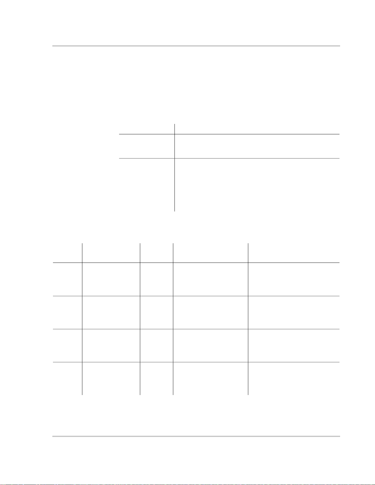
Warning Types
Faults and Warnings
There are two types of warnings: automatic and manual. When the XW Inverter/
Charger detects a warning condition, it displays a warning message on the System
Control Panel.
Table 4-1 describes how they differ in their behavior and in how you can respond
to them when they appear on the System Control Panel.
Table 4-1
Warning type Behavior
Automatic warning Clear automatically if the fault condition that generated the
Manual warning Require you to acknowledge them before you can proceed with
Table 4-2 provides descriptions of the warning messages and solutions.
Table 4-2
Warning
Number
W3 AC1 Input L1 Und e r
Warning Messages
System Control
Panel Message
Voltage
Warning Types and Behavior
message goes away. You can also acknowledge automatic
warnings without waiting for them to clear automatically.
configuring or operating the XW Inverter/Charger. Manual
warnings are usually in the form of a Yes/No question that you
may acknowledge by pressing the Enter button on the System
Control Panel for Yes and the Exit button for No.
Refer to the System Control Panel Owner’s Guide for more
information.
Warning
Type Cause Solution
Automatic AC Under Voltage Warning
(AC1 Line 1 input is at or
below the AC1 Lo Volt
setting, plus 5 V)
Check AC input voltage. Check or
adjust low AC input voltage setting
(AC1 Lo Volt).
W4 AC1 Input L1 Over
Voltage
W7 AC1 Input L2 Und e r
Voltage
W8 AC1 Input L2 Over
Voltage
975-0240-01-01 4–11
Automatic AC Over Voltage Warning
(AC1 Line 1 input is at or
above the AC1 Hi Volt
setting, minus 2 V)
Automatic AC Under Voltage Warning
(AC1 Line 2 input is at or
below the AC1 Lo Volt
setting, plus 5 V)
Automatic AC Over Voltage Warning
(AC1 Line 2 input is at or
above the AC1 Hi Volt
setting, minus 2 V)
Check AC input voltage. Check or
adjust high AC input voltage
setting (AC1 Hi Volt).
Check AC input voltage. Check or
adjust low AC input voltage setting
(AC1 Lo Volt).
Check AC input voltage. Check or
adjust high AC input voltage
setting (AC1 Hi Volt).
Page 78

Troubleshooting
Table 4-2
Warning
Number
W11 AC2 Input L1 Over
W12 AC2 Input L1 Under
W13 AC2 Input L2 Over
W14 AC2 Input L2 Under
W44 Battery Over
Warning Messages
System Control
Panel Message
Voltage
Voltage
Voltage
Voltage
Temperature
Warning
Type Cause Solution
Automatic AC Over Voltage Warning
(AC2 Line 1 input is at or
above the AC2 Hi Volt
setting, minus 2 V)
Automatic AC Under Voltage Warning
(AC2 Line 1 input is at or
below the AC2 Lo Volt
setting, plus 10 V)
Automatic AC Over Voltage Warning
(AC2 Line 2 input is at or
above the AC2 Hi Volt
setting, minus 2 V)
Automatic AC Under Voltage Warning
(AC2 Line 2 input is at or
below the AC2 Lo Volt
setting, plus 10 V)
Automatic Battery Over Temperature
Warning. Battery
temperature is over 50 °C.
Check AC input voltage. Check or
adjust high AC input voltage
setting (AC2 Hi Volt).
Check AC input voltage. Check or
adjust low AC input voltage setting
(AC2 Lo Volt).
Check AC input voltage. Check or
adjust high AC input voltage
setting (AC2 Hi Volt).
Check AC input voltage. Check or
adjust low AC input voltage setting
(AC2 Lo Volt).
Check battery voltage and battery
cable connections. Stop charging,
if necessary. Check for excessive
ambient temperature and adequate
ventilation in the battery
compartment
W45 Capacitor over
temperature
W48 DC Under Voltage Automatic Battery voltage is below
W49 DC Over Voltage Automatic Battery voltage is above
4–12 975-0240-01-01
Automatic DC Bulk Capacitor over
temperature (100 °C)
46 V.
68 V.
Ensure adequate ventilation around
the XW Inverter/Charger. Reduce
the AC loads.
Check for the correct battery
voltage at the inverter’ s DC input
terminals. Check for an external
DC load on the batteries. Check
condition of batteries and recharge
if possible or reduce your Low Batt
Cut Out setting.
Turn off or check additional
charging sources to batteries.
Check battery cables.
Check for the correct battery
voltage at the inverter’ s DC input
terminals. Ensure your DC source
is regulated below your high
battery cut out or increase your
High Batt Cut Out setting.
Page 79
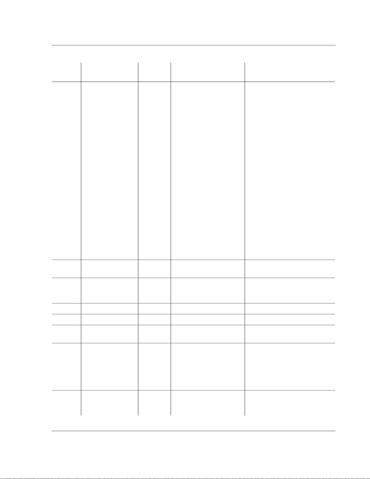
Faults and Warnings
Table 4-2
Warning
Number
W57 FET1 Over
Warning Messages
System Control
Panel Message
Temperature
Warning
Type Cause Solution
Automatic Internal temperature is over
85 °C.
AC input voltage may be
too high while charging.
Operating too large of a load
for too long while inverting.
Ambient temperature may
be high.
Inverter cooling fan may
have failed.
Inverter airflow intake may
be blocked.
Check for high input AC voltage.
Remove excessive loads.
Let inverter cool down and try
restarting.
Hold a piece of paper to inverter
vents to check the fan. If the fan
has failed, have the inverter
serviced.
Increase clearance around the
inverter or unclog the fan air
intake.
Charging setting is too high
based on ambient
temperature around inverter.
W58 FET2 Over
Temperature
W63 AC Overload Automatic Excessive load on the AC
W64 AC Overload L1 Automatic See W63. See W63.
W65 AC Overload L2 Automatic See W63. See W63.
W68 Transformer Over
Temperature
W94 Remote Power Off Automatic The unit has been turned off
W95 Equalize Abort Manual Equalization terminated
Automatic See W57. See W57.
output.
Automatic See W57. See W57.
with a Remote Power Off
switch.
abnormally because of
interrupted AC input.
Lower the Max Charge Rate
setting.
Check for loads above the
inverter’s capacity. Turn off some
loads if necessary.
No action required. The unit stops
inverting or charging immediately,
and shuts down after five seconds.
If the unit is configured as a
master, it signals other network
devices to also shut down.
Wait until AC input (utility grid)
returns to in-tolerance condition.
975-0240-01-01 4–13
Page 80

Troubleshooting
Table 4-2
Warning
Number
W96 Cannot Equalize Manual The selected battery type
W97 Battery temp sensor
W500 Lost network
W501 Inv/Chg is trying to
Warning Messages
System Control
Panel Message
failure.
connection
fix a memory
problem
Warning
Type Cause Solution
should not be equalized.
Automatic Battery Temperature Sensor
Shorted
Automatic Lost network connection Check network cables.
Manual Non-volatile memory
warning
Change battery type if your
batteries should be equalized. Gel
or AGM batteries should not be
equalized.
Replace battery temperature
sensor.
Normal operation may return or
may go to fault. Turn inverter/
charger off and on to resume
normal operation.
4–14 975-0240-01-01
Page 81

Fault Messages
Faults and Warnings
When the XW Inverter/Charger detects a fault condition, the fault is displayed on
the System Control Panel. The XW Inverter/Charger also illuminates the Fault
light on the System Control Panel and inverter information panel. A fault affects
the operation of the unit. See “Fault Types” on page 4–16 for an explanat ion of the
different fault types.
You can view the 20 most recent fault messages on the System Control Panel by
selecting Fault Log from the Device Info menu in the XW Inverter/Charger Setup
Menu.
If several faults occur before you can acknowledge or clear them, they are
displayed together on a fault list. This list contains messages from every Xanbusenabled device, not just the XW Inverter/Charger. You can select a message and
view its details from the fault list.
To view a message from a fault list:
1. On the list, use the up arrow or down arrow button to highlight the message
you want to view.
2. Press Enter.
The complete message appears.
After viewing the message, you can return to the fault list by pressing Exit or
continue to the menu for the device that caused the fault by pressing Enter. Each
time you return to the list after viewing a complete message, the viewed message
is removed from the list.
If you have left the fault list, you can view faults at any time from the System
Settings menu.
To view a fault list:
1. On the Select Device menu, highlight System Settings and press Enter.
2. On the System Settings menu, highlight View Fault List.
3. Press Enter.
975-0240-01-01 4–15
Page 82

Troubleshooting
Fault Types
There are three types of fault messages: automatic faults, manual faults, and
escalating automatic faults. Table 4-3 describes how they differ in their behavior
and how you can respond to them when they appear on the XW System Control
Panel.
Table 4-3
Fault type Behavior
Automatic faults Clear automatically if the fault condition that generated the
Manual faults Require you to clear them by:
Escalating automatic
faults
Inverter Operation After Faults
XW Inverter/Charger operation changes when a fault occurs. How the operation
changes depends on the operating state of the unit when the fault occurred—
inverting, charging, grid or generator support, AC bypass, and so on—and on
which fault has occurred.
Fault Types and Behaviors
message goes away. You can also acknowledge automatic faults
without waiting for them to clear automatically.
• selecting Clear Faults on the Main XW Inverter/Charger
menu or on the menu for the Xanbus-enabled device that
generated the fault (if the fault condition still exists, the fault
message reappears)
• correcting the condition that caused the fault.
Clear automatically if the fault condition goes away, just like an
automatic fault.
However, if an escalating automatic fault occurs several times
within a defined time period, the escalating automatic fault
becomes a manual fault, requiring user intervention. For
example, if an AC Overload fault occurs three times in five
minutes, it will no longer clear itself and become a manual fault.
Then you must identify the problem, correct the fault condition,
and clear the fault.
Table 4-4
Faults State when Faults Occur Action After Faults
F1, F2: AC Output Inverting Unit stops inverting and waits for
F3 to F10: AC1 Input
Voltage and Frequency
F11 to F 16: AC2 Inpu t
Voltage and
Frequency.
4–16 975-0240-01-01
Inverter Operation After Faults
AC1 input is the
preferred source and
qualified.
AC2 input is the
preferred source and
qualified.
nominal AC output voltage level,
or a manual clear from user.
Unit begins inverting (if inverter is
enabled) or disengages AC1 and
waits for nominal AC1 input (if
inverting is disabled).
Unit begins inverting (if inverter is
enabled) or disengages AC2 and
waits for nominal AC2 input (if
inverting is disabled).
Page 83

Faults and Warnings
Table 4-4
Faults State when Faults Occur Action After Faults
F17 to F22: Relay
Welded
F23 to F40: AntiIslanding
F41, F42: Aux power
supply voltage
F44: Battery Over
Temp
F45: Capacitor Over
Temp
F47 to F49: DC
Voltage
F63 to F65: AC
Overload
Inverter Operation After Faults
Inverting Unit stops inverting and waits for
Grid Support (Peak Load
Shaving or Selling)
Unit has qualified AC
input.
Any state. If inverting, the unit shuts down
Unit is inverting or has
qualified AC input and is
preparing to charge.
Inverting or Grid Support Unit stops inverting and waits to
user to clear fault.
Moves to AC bypass and waits for
nominal grid conditions to return
for a minimum of five minutes.
Unit shuts down and waits for
nominal AC output voltage level,
or a manual clear from user.
and waits for the temperature to
return to nominal value. If in any
of the AC-interactive states
(charging, peak load shaving, sell,
gen support), the unit goes into AC
bypass mode until the temperature
returns to the nominal value. If the
unit is not in AC bypass, it shuts
down until the temperature returns
to nominal value. After these faults
clear, the unit returns to its
previous operating state.
If inverting, the unit shuts down
and waits for nominal voltage. If
operating with a qualified AC
source, the unit charges if charging
is enabled, or remains in AC
bypass if charging is disabled.
qualify AC. Unit waits for user to
manually clear fault.
975-0240-01-01 4–17
Page 84

Troubleshooting
Table 4-5 provides descriptions of the fault messages and solutions. If you are
unable to resolve the problem after referring to this table, contact your dealer or
Customer Service.
Table 4-5
Fault
Number Message Fault Type Cause Solution
F1 AC Output Und e r
F2 AC Output Over
F3 AC1 Input L1
Fault Messages
Voltage
Voltage
Under Voltage
Escalating
Auto Fault.
Must occur 3
times in 2
minutes before
becoming a
manual fault.
Escalating
Auto Fault.
Must occur 3
times in 30
seconds before
becoming a
manual fault.
Automatic AC1 under-voltage
AC under-voltage
shutdown at 108 V. The
inverter has shut down to
protect the loads.
AC over-voltage
shutdown at 135 V. The
inverter has shut down to
protect the loads.
shutdown at the AC1 Lo
Volt setting.
Clear the fault and attempt restart. If
problem persists, call customer
service.
Clear the fault and attempt restart. If
problem persists, call customer
service.
Fault clears when voltage rises
above the AC1 Lo Volt setting. If
fault persists, check AC input
voltage. Check and adjust AC input
low voltage setting.
F4 AC1 Input L1 Over
Voltage
F5 AC1 Input L1
Under Frequency
F6 AC1 Input L1 Over
Frequency
F7 AC1 Input L2
Under Voltage
4–18 975-0240-01-01
Automatic AC1 over-voltage
shutdown at the AC1 Hi
Volt setting.
Automatic AC1 under-frequency
shutdown at AC1 Lo
Freq setting.
Automatic AC1 over-frequency
shutdown at the AC1 Hi
Freq setting.
Automatic AC1 under-voltage
shutdown at the AC1 Lo
Volt setting.
Fault clears when voltage falls
below the AC1 Hi Volt setting. If
fault persists, check AC input
voltage. Check and adjust AC input
high voltage setting.
Fault clears when frequency rises
above the AC1 Lo Freq setting. If
fault persists, check AC input
frequency. Check and adjust AC
input low frequency setting.
Fault clears when frequency falls
below the AC1 Hi Freq setting. If
fault persists, check AC input
frequency. Check and adjust AC
input high frequency setting.
Fault clears when voltage rises
above the AC1 Lo Volt setting. If
fault persists, check AC input
voltage. Check and adjust AC input
low voltage setting.
Page 85

Faults and Warnings
Table 4-5
Fault
Number Message Fault Type Cause Solution
F8 AC1 Input L2 Over
F9 AC1 Input L2
F10 AC1 Input L2 Over
F11 AC2 Input L1 Over
Fault Messages
Voltage
Under Frequency
Frequency
Voltage
Automatic AC1 over-voltage
shutdown at the AC1 Hi
Volt setting.
Automatic AC1 under-frequency
shutdown at the AC1 Lo
Freq setting.
Automatic AC1 over-frequency
shutdown at the AC1 Hi
Freq setting.
Automatic AC2 over-voltage
shutdown at the AC2 Hi
Volt setting.
Fault clears when voltage falls
below the AC1 Hi Volt setting. If
fault persists, check AC input
voltage. Check and adjust AC input
high voltage setting.
Fault clears when frequency rises
above the AC1 Lo Freq setting. If
fault persists, check AC input
frequency. Check and adjust AC
input low frequency setting.
Fault clears when frequency falls
below the AC1 Hi Freq setting. If
fault persists, check AC input
frequency. Check and adjust AC
input high frequency setting.
Fault clears when voltage falls
below the AC2 Hi Volt setting. If
fault persists, check AC input
voltage. Check and adjust AC input
high voltage settings.
F12 AC2 Input L1
Under Voltage
F13 AC2 Input L2 Over
Voltage
F14 AC2 Input L2
Under Voltage
F15 AC2 Input L1 Over
Frequency
Automatic AC2 under-voltage
shutdown at the AC2 Lo
Volt setting.
Automatic AC2 over-voltage
shutdown (AC Line 2
input) at the AC2 Hi V olt
setting.
Automatic AC2 under-voltage
shutdown (AC Line 2
input) at the AC2 Lo V olt
setting.
Automatic AC2 over-frequency
shutdown (AC Line 1
input) at the AC2 Hi
Freq setting.
Fault clears when voltage rises
above the AC2 Lo Volt setting. If
fault persists, check AC input
voltage. Check and adjust AC input
low voltage setting.
Fault clears when voltage falls
below the AC2 Hi Volt setting.
Check AC input voltage. Check and
adjust AC input high voltage
settings.
Fault clears when voltage rises
above the AC2 Lo Volt setting.
Check AC input voltage. Check and
adjust AC input low voltage setting.
Fault clears when frequency falls
below the AC2 Hi Freq setting.
Check AC input frequency. Check
and adjust AC input high frequency
setting.
975-0240-01-01 4–19
Page 86

Troubleshooting
Table 4-5
Fault
Number Message Fault Type Cause Solution
F16 AC2 Input L1
F17 Relay(s) Welded Manual The AC1 L1 transfer
F18 Relay(s) Welded Manual AC1 L2 transfer relay is
F19 Relay(s) Welded Manual AC2 L1 transfer relay is
Fault Messages
Under Frequency
Automatic AC2 under-frequency
shutdown (AC Line 1
input) at the AC2 Lo
Freq setting.
relay is bad or an AC
source was wired
directly to the AC
output.
bad or an AC source was
wired directly to the AC
output.
bad or an AC source was
wired directly to the AC
output.
Fault clears when frequency rises
above the AC2 Lo Freq setting.
Check AC input frequency. Check
and adjust AC input low frequency
setting.
Disconnect the inverter’s output
wiring. If error continues, have unit
serviced.
See F17.
See F17.
F20 Relay(s) Welded Manual AC2 L2 transfer relay is
bad or an AC source was
wired directly to the AC
output.
F21 Relay(s) Welded Manual An unidentified transfer
relay is bad or an AC
source was wired
directly to the AC
output.
F22 Relay(s) Welded Manual An unidentified L1
transfer relay is bad or an
AC source was wired
directly to the AC
output.
F23 AI Over Frequency Automatic Over-frequency anti-
islanding, caught by the
AC qualification limit.
See F17.
See F17.
See F17.
No action required. The inverter
stops selling and disconnects from
the grid. When the fault clears, a
five-minute timer begins counting
down. The inverter does not sell
again until grid voltage and
frequency are within range for five
minutes.
4–20 975-0240-01-01
Page 87

Faults and Warnings
Table 4-5
Fault
Number Message Fault Type Cause Solution
F24 AI Under
F25 AI Over Frequency Automatic Over-frequency anti-
F26 AI Under
F27 AI L1 Over Voltage Automatic Over-voltage anti-
F28 AI L2 Over Voltage Automatic See F27. See F23.
F29 AI L1L2 Over
F30 AI L1L2 Over
Fault Messages
Frequency
Frequency
Voltage
Voltage
Automatic Under-frequency anti-
islanding, caught by the
AC qualification limit.
islanding, 60.4 Hz
Automatic Under-frequency anti-
islanding, 59.4 Hz
islanding, fast
disconnect, 135 Vac.
Automatic Over-voltage anti-
islanding fault, caught by
the qualification limit,
voltage difference
between L1 and L2.
Automatic Over-voltage anti-
islanding, fast
disconnect, 270 V.
See F23.
See F23.
See F23.
See F23.
See F23.
See F23.
F31 AI L1 Over Voltage Automatic Over-voltage anti-
islanding, slow
disconnect, 130 V.
F32 AI L2 Over Voltage Automatic Over-voltage anti-
islanding, slow
disconnect, 130 V.
F33 AI L1L2 Over
Voltage
F34 AI L1 Under
Voltage
F35 AI L2 Under
Voltage
F36 AI L1L2 Under
Voltage
F37 AI L1 Under
Voltage
Automatic Over-voltage anti-
islanding, slow
disconnect, 260 V.
Automatic Under-voltage anti-
islanding, slow
disconnect, 107 V.
Automatic See F34. See F23.
Automatic See F34. See F23.
Automatic Under-voltage anti-
islanding, fast
disconnect, 66 Vac.
See F23.
See F23.
See F23.
See F23.
See F23.
975-0240-01-01 4–21
Page 88

Troubleshooting
Table 4-5
Fault
Number Message Fault Type Cause Solution
F38 AI L2 Under
F39 AI L1L2 Under
F40 AI L1L2 Under
F41 APS Under Voltage Escalating
F42 APS Over Voltage Escalating
Fault Messages
Voltage
Voltage
Voltage
Automatic See F37. See F23.
Automatic Under-voltage anti-
islanding fault, caught by
the qualification limit,
voltage difference
between L1 and L2.
Automatic Under-voltage anti-
islanding, fast
disconnect, 132 V.
Auxiliary power supply
Auto Fault.
Must occur 3
times in 30
seconds before
becoming a
manual fault.
Auto Fault.
Must occur 3
times in 30
seconds before
becoming a
manual fault.
under-voltage shutdown
Auxiliary power supply
over-voltage shutdown
See F23.
See F23.
Clear the fault and attempt restart. If
problem persists, call customer
service.
Clear the fault and attempt restart. If
problem persists, call customer
service.
F44 Battery Over
Temperature
F45 Capacitor Over
Temperature
F46 Controller fault Manual Controller fault Service requ ired.
4–22 975-0240-01-01
Automatic Battery over-
temperature shutdown at
60 °C.
Automatic Capacitor over-
temperature shutdown at
150 °C.
Clear the fault and attempt restart.
Stop charging, check battery voltage
and temperature. Check for
excessive ambient temperature and
adequate ventilation in the battery
compartment.
Clear the fault and attempt restart.
Ensure adequate ventilation around
the XW Inverter/Charger. Reduce
AC loads.
Page 89

Faults and Warnings
Table 4-5
Fault
Number Message Fault Type Cause Solution
F47 DC Under Voltage Automatic DC under-voltage
F48 DC Under Voltage Automatic DC under-voltage
F49 DC Over Voltage Automatic DC over-voltage
Fault Messages
shutdown (immediate)
occurs if DC voltage is
below 16 Vdc (24 V) or
32 Vdc (48 V)
The fault clears and the
inverter restarts when
DC voltage reaches
23 Vdc (24 V) or 46 Vdc
(48 V).
shutdown occurs if DC
voltage is below 20 Vdc
(24 V) or 44 Vdc (48 V).
shutdown. Occurs if DC
voltage is above 32 Vdc
(24 V) or 70 Vdc (48 V).
Check for the correct battery voltage
at the inverter’s DC input terminals.
Check for an external DC load on
the batteries. Check condition of
batteries and recharge if possible.
See F47.
Clear the fault and attempt restart.
Ensure battery voltage is below
29 Vdc (24 V ) or 58 Vdc (48 V) at
XW Inverter/Charger terminals.
Check all other charging source
outputs, battery cables. Ensure your
DC source is regulated below your
high battery cut out or increase your
Hi Batt Cut Out setting.
F52 EEPROM Error Manual No action. Clear fault and resume
operating or configuring the unit. If
the fault persists, have the unit
serviced.
F53 EEPROM Error Manual See F52.
F54 EEPROM Error Manual See F52.
F55 EEPROM Error Manual See F52.
F56 EEPROM Error Manual See F52.
975-0240-01-01 4–23
Page 90

Troubleshooting
Table 4-5
Fault
Number Message Fault Type Cause Solution
F57 FET1 Over
Fault Messages
Temperature
Shutdown
Automatic Internal temperature is
over 105 °C.
AC input voltage may be
too high while charging.
Operating too large of a
load for too long while
inverting.
Ambient temperature
may be high.
Inverter cooling fan may
have failed.
Inverter airflow intake
may be blocked.
Fault clears when temperature drops
to 75 °C.
Check for high input AC voltage.
Remove excessive loads.
Let inverter cool down and try
restarting.
Hold a piece of paper to inverter
vents to check the fan. If the fan has
failed, have the inverter serviced.
Increase clearance around the
inverter or unclog the fan air intake.
F58 FET2 Over
Temperature
Shutdown
F59 GOCFG process
failed
F63 AC Overload Escalating
F64 AC Overload L1 Escalating
Automatic See F57. See F57.
Manual Auto-configuration
Auto Fault.
Must occur 3
times in 5
minutes before
becoming a
manual fault.
Auto Fault.
Must occur 3
times in 5
minutes before
becoming a
manual fault.
Charging setting is too
high based on ambient
temperature around
inverter.
process failed.
Excessive load on the
AC output.
Excessive load on the
AC output.
Lower the Max Charge Rate
setting.
Retry the “Copy From?” procedure,
or configure the unit manually.
Check for loads above the inverter’s
capacity. Turn off some loads if
necessary.
See F63
4–24 975-0240-01-01
Page 91

Faults and Warnings
Table 4-5
Fault
Number Message Fault Type Cause Solution
F65 AC Overload L2 Escalating
F66 System
F67 Watchdog Error Manual Service required.
F68 Transformer Over
Fault Messages
Configuration Fault
Temperature
Excessive load on the
Auto Fault.
Must occur 3
times in 5
minutes before
becoming a
manual fault.
Automatic Multi-Unit
Automatic The transformer
AC output.
Configuration settings
are incorrect.
temperature is over
140 °C.
See F63.
Ensure only one unit is configured
as the master. Ensure each unit has a
unique Device Number, and that
Connections have been configured
correctly. See “Connections Menu”
on page 3–26.
The fault clears when the
transformer temperature falls to
125 °C. Ensure adequate ventilation
around the XW Inverter/Charger.
Reduce AC loads.
F69 External Sync
Failed
F500 Silicon Serial ID
Failure
Manual Check connections and cable on
external AC sync port. In a singleinverter system, nothing must be
plugged into the AC sync port. Clear
fault and try again. If these steps
fail, the unit requires service.
Manual Silicon Serial ID Failure S ervice required.
975-0240-01-01 4–25
Page 92

4–26
Page 93

A
Specifications
Appendix A, “Specifications” provides the electrical and environmental
specifications for the XW Inverter/Charger.
Page 94

Specifications
Electrical Specifications
Table A-1
XW Series Inverter/Charger Electrical Specific ations
Model XW6048-120/240-60 XW4548-120/240-60 XW4024-120/240-60
Continuous Output Power 6,000 W 4,500 W 4,000 W
Surge Rating (10 seconds) 12,000 W 9,000 W 8,000 W
Surge Current L-n: 105 A
L-L: 52.5 A
rms
rms
(7 sec)
(7 sec)
L-n: 75 A
L-L: 40 A
(20 sec)
rms
(20 sec)
rms
L-n: 70 A
L-L: 35 A
rms
rms
(7 sec)
(7 sec)
Waveform True Sine Wave
Idle Consumption—invert mode, no load 28 W 26 W 24 W
Idle Consumption—search mode < 8 W
AC Output Voltage L-n: 120 Vac ±3 %
L-L: 240 Vac ±3%
AC Input voltage range (Bypass/Charge
Mode)
AC Input Current (maximum 75%
imbalance between L1-n, L2-n)
L-n: 41.2 A
L-L: 27.5 A
L-n: 80–150 Vac (120 V nominal)
L-L: 160–270 Vac (240 V nominal)
L-n: 30.9 A
L-L: 20.6 A
L-n: 27.5 A
L-L: 18.3 A
AC Input Breaker 60 A double-pole
AC Input Frequency Range (Bypass/
Charge Mode)
AC1 voltage range—Sell Mode
a
(automatically adjusts when entering Sell
55–65 Hz (default)
44–70 Hz (allowable)
L-n: 108–130 ±1.5 V ac
L-L: 214–260 ±3.0 Vac
Mode)
AC1 Frequency range—Sell Mode
a
59.4–60.4 ±0.05 Hz
(automatically adjusts when entering Sell
Mode)
AC Output Current (maximum 75%
imbalance between L1-n, L2-n)
L-n: 37.5 A
L-L: 25.0 A
L-n: 28.1 A
L-L: 18.8 A
L-n: 25.0 A
L-L: 16.7 A
AC Output Breaker 60 A double-pole
AC Output Frequency 60.0 ±0.1 Hz
Total Harmonic Distortion < 5%
Automatic Transfer Relay 60 A
Auxiliary Relay Output 0–12 Vdc, maximum 250 mA DC
CEC Weighted Efficiency 93.5% 93% 91%
CEC Power Rating 6,000 W 4,500 W 4,000 W
DC Input Voltage (Nominal) 50.4 Vdc 50.4 Vdc 25.2 Vdc
DC Input Voltage Range 44–64 Vdc 44–64 Vdc 22–32 Vdc
DC Current at Rated Power 127 A 95 A 171 A
Continuous Charge Rate at L-L voltage 100 A 85 A 150 A
Power Factor Corrected Charging PF (0.98)
a.This unit or system is provided with fixed trip limits and shall not be aggregated above 30 kW on a single Point of
Common Connection
A–2 975-0240-01-01
Page 95

XW Inverter/Charger Overload Capability
Loads presented to the inverter are seldom constant. T ypically, large loads are operated for
only short periods of time. In order to provide the maximum utility, Xantrex inverters are
allowed to operate at power levels that exceed their continuous power ratings. This graph
shows how loads that are larger than the inverter can sustain continuously can be operated
for useful periods of time.
The length of time that the inverter can operate at high power is limited by temperature.
When large loads are run, the inverter’s temperature increases. At the point where more
heat is created in the inverter than can be dissipated, its ability to operate becomes time
limited.
Electrical Specifications
60
55
50
45
40
35
30
25
20
15
A C O u tp u t C u rr en t [A r m s ]
10
5
0
1 10 100 1000 10000
120
110
100
90
80
70
60
50
40
30
AC Output Current [Arm s]
20
10
0
1 10 100 1000 10000
X W 6 0 4 8 AC O v e r lo a d c a p a b ilit y (L 1 - L 2 ) 2 4 0 V
t [S e c o n d s)
X W 6 0 4 8 AC O v e r lo a d c a p a b ilit y (L 1 - n ) 1 2 0 V u n b a la n c e d A C lo a d
t [Seconds)
Figure A-1
XW Inverter/Charger AC Overload Capability
975-0240-01-01 A–3
Page 96
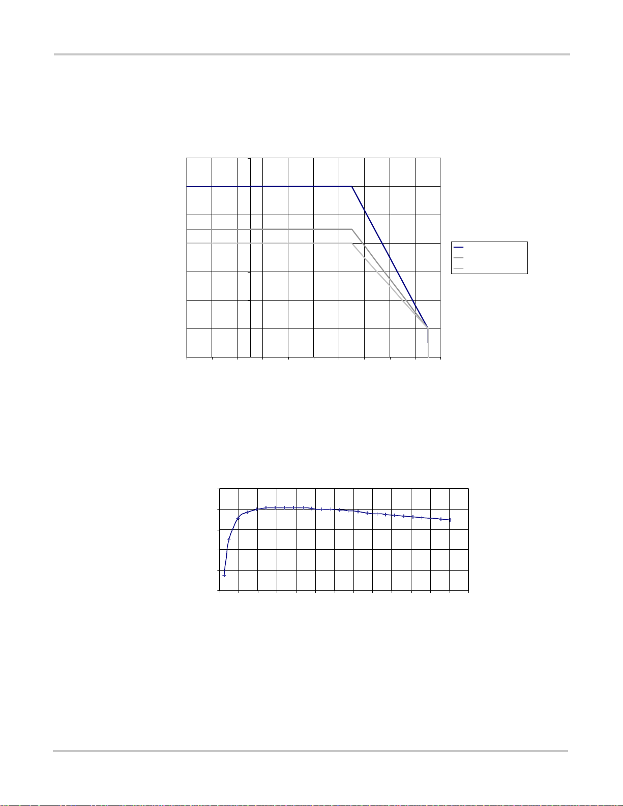
Specifications
Output Power Versus Ambient Temperature
When the internal temperature of the XW Inverter/Charger exceeds its rated range, the
unit reduces it energy output to ensure maximum component ratings are not excee ded.
XW Series Power Derating
7000
6000
5000
4000
3000
2000
1000
-25-15-5 5 15253545556575
Figure A-2
Output Power Versus Ambient Temperature
XW Inverter/Charger Efficiency
Inverting Efficiency (Typical)
100
95
90
XW6048-Pwr_der
XW4548-Pwr_der
XW4024-Pwr_der
0
85
Efficiency (%)
80
75
0.0 0.5 1.0 1.5 2.0 2.5 3.0 3.5 4.0 4.5 5.0 5.5 6.0 6.5
Output Power (kW)
A–4 975-0240-01-01
Page 97

Charging Efficiency (Typical)
Mechanical Specifications
100
95
Effici ency (% )
Sell Mode Efficiency (Typical)
90
85
80
7 1525354555657589100
Batt er y Cur r en t ( Amps )
100
97
94
91
Efficiency (%)
88
Power Fa ct or
Efficiency
85
0.0 0.5 1.0 1.5 2.0 2.5 3.0 3.5 4.0 4.5 5.0 5.5 6.0 6.5
Expo rt Pow e r (k W)
Mechanical Specifications
Table A-2
Model XW6048-120/240-60 XW4548-120/240-60 XW4024-120/240-60
Supported Battery Types Flooded (default), Gel, AGM, Custom
Battery bank size 100–2000 Ah
Non Volatile Memory Yes
Display Panel Status LEDs indicate AC In status, faults/warnings, equalize mode, battery level.
Multiple Unit Configurations Up to 3 parallel units in 120/240 split-phase configuration
975-0240-01-01 A–5
XW Series Inverter/Charger Mechanical Specifications
Three-character display indicates output power or charge current, fault/warning codes.
On/Off and equalize button
Page 98

Specifications
Table A-2
Model XW6048-120/240-60 XW4548-120/240-60 XW4024-120/240-60
System Network Xanbus (publish-subscribe network, no need for hub s or special cards)
Emissions FCC Class B
Regulatory approvals UL 1741 1st Edition: 2005 Version, CSA 107.1-01
Enclosure Type NEMA Type 1—Indoor
Rated T emperature Range (meets all
specifications)
Operational Temperature Range -13–158 °F (-25–70 °C)
Storage Temperature Range -40–185 °F (-40–85 °C)
Inverter Dimensions (H × W × D) 23 × 16 × 9" (580 × 410 × 230 mm)
Shipping Dimensions (H × W × D) 28 × 22 ¼ × 10 ½" (711 × 565 × 267 mm)
Inverter Weight 125 lb (57 kg) 115 lb (52 kg) 115 lb (52 kg)
Shipping Weight 132 lb (60 kg) 122 lb (55 kg) 122 lb (55 kg)
XW Series Inverter/Charger Mechanical Specifications
32–104 °F (0–40 °C)
Accessories
Accessory Part Number
Power Distribution Panel 865-1015
Conduit Box 865-1025
Inverter #2 Connection Kit 865-10 20
XW-MPPT60 -15 0 Solar Charge Controller 865-1030
XW System Control Panel (System Control Panel II) 865-1050
XW Automatic Generator Start 865-1060
Network cables 3 ft (0.9 m): 809-0935
5 ft (1.5 m): 809-0936
7 ft (2.0 m): 809-0937
10 ft (3.0 m): 809-0938
14 ft (4.3 m): 809-0939
25 ft (7.6 m): 809-0940
50 ft (15.2 m): 809-0941
75 ft (22.9 m): 809-0942
Network terminators Male (2 per pack): 809-0901
Female (2 per pack): 809-0905
A–6 975-0240-01-01
Page 99

B
Default Settings
Appendix B contains the default configuration settings and ranges for
the XW Inverter/Charger. Configuration settings can be viewed and
changed using the XW System Control Panel.
Page 100

Default Settings
Default Settings and Ranges
Figure B-1 shows the XW Inverter/Charger configuration menus as they appear
on the XW System Control Panel.
XW6048 00: Adv
[XW6048 01]
XW6048 00:Inv
XW6048 00:Chg
XW6048 00:AC
XW6048 00:Grid
XW6048 00:Gen
XW6048 00: Aux
[44V]
[10s]
[70V]
[50W]
[2s]
[Flooded]
[440Ah]
[100%]
[2-Stage]
[Warm]
[50V]
[180min]
[12:00AM]
[12:00AM]
[AC1]
[60A]
[106V]
[132V]
[55Hz]
[65Hz]
[60A]
[80V]
[138V]
[55Hz]
[65Hz]
[54V]
[Disabled]
[28A]
[Disabled]
[60A]
[12:00AM]
[12:00AM]
[Disabled]
[10A]
[ManualOff]
[ActHi]
[LowBattV]
[42V]
[1sec]
[48V]
[1sec]
Custom Settings
[Disabled]
[64.0V]
[57.6V]
[57.6V]
[54.0V]
[108mV/C]
Figure B-1
XW6048 00: Multi
Configuration Menu Map (Advanced)
[XW6048]
[00]
[SplitPhMstr]
Connections
[HouseBatt1]
[ACLoad1]
[Grid1]
[Gen1]
B–2 975-0240-01-01
 Loading...