

Page 1

GPIB and Ethernet
Interface for
XTR Series
Programmable DC
GPIB
ENET
Operating Manual
Power Supplies
Page 2

Page 3

XTR 850W GPIB and
Ethernet Interface Option
Operating Manual
Page 4

About Xantrex
Xantrex Technology Inc. is a world-leading supplier of advanced power electronics and controls with products
from 50 watt mobile units to 2.5 MW utility-scale systems for wind, solar, batteries, fuel cells, microturbines,
and backup power applications in both grid-connected and stand-alone systems. Xantrex products include
inverters, battery chargers, programmable power supplies, and variable speed drives that convert, supply, control,
clean, and distribute electrical power.
Trademarks
Xantrex is a registered trademark of Xantrex International.
Other trademarks, registered trademarks, and product names are the property of their respective owners and are
used herein for identification purposes only.
Notice of Copyright
GPIB and Ethernet Interface for XTR Series Programmable DC Power Supplies: Operating Manual© July 2007
Xantrex International. All rights reserved.
U
NLESS SPECIFICALLY AGREED TO IN WRITING, XANTREX TECHNOLOGY INC. (“XANTREX”)
(
A) MAKES NO WARRANTY AS TO THE ACCURACY, SUFFICIENCY OR SUITABILITY OF ANY TECHNICAL OR OTHER
INFORMATION PROVIDED IN ITS MANUALS OR OTHER DOCUMENTATION.
(
B) ASSUMES NO RESPONSIBILITY OR LIABILITY FOR LOSSES, DAMAGES, COSTS OR EXPENSES, WHETHER SPECIAL,
DIRECT, INDIRECT, CONSEQUENTIAL OR INCIDENTAL, WHICH MIGHT ARISE OUT OF THE USE OF SUCH
INFORMATION. THE USE OF ANY SUCH INFORMATION WILL BE ENTIRELY AT THE USER’S RISK; AND
(C) REMINDS YOU THAT IF THIS MANUAL IS IN ANY LANGUAGE OTHER THAN ENGLISH, ALTHOUGH STEPS HAVE
BEEN TAKEN TO MAINTAIN THE ACCURACY OF THE TRANSLATION, THE ACCURACY CANNOT BE GUARANTEED.
A
PPROVED XANTREX CONTENT IS CONTAINED WITH THE ENGLISH LANGUAGE VERSION WHICH IS POSTED AT
WWW.XANTREX.COM.
Date and Revision
July 2007 Revision A
Part Number
M370046-06
Product Numbers (FGAs)
GPIB Ethernet
GPIB-XTR1 ENET-XTR1
Contact Information
Telephone: 1 800 733 5427 (toll free North America)
Fax: 1 858 678 4482 (direct)
Email: prg.info@xantrex.com
Web: www.xantrex.com
1 858 450 0085 (direct)
Page 5

About This Manual
Purpose
This Operating Manual provides explanations and procedures for
programming the XTR 850 Watt Series Programmable DC Power Supply
from the GPIB interface and connecting and configuring the power supply
to the Ethernet.
Scope
The Manual covers the GPIB and Ethernet interface options only. Refer to
the XTR 850 Watt Series Programmable DC Power Supply Operating
Manual (Part number: M370046-01) for installation, operating procedures,
setup, calibration and troubleshooting for your power supply.
Audience
The Manual is intended for the user who is familiar with electronic power
supplies, Constant Current and Constant Voltage operating modes and the
control of output power. The user should be familiar with practicing safe
techniques while making supply or pin connections. The user should also
have experience with network-based communications software and
protocols.
Organization
This Manual is organized into two chapters, two appendices, and provides
Warranty and Product information.
Chapter 1, “GPIB” provides information and procedures on programming
the XTR 850 Watt Series Programmable DC Power Supply from the GPIB
(General Purpose Interface Bus) interface.
Chapter 2, “Ethernet (ENET)” provides information and procedures to
connect and configure the power supply to the ENET.
Appendix A, “Troubleshooting” provides troubleshooting information for
the combined ENET and RS-485 communication and for ENET
communication.
Appendix B, “Links” provides the Web site links for relevant third party
vendors.
M370046-06 iii
Page 6

About This Manual
Conventions Used
The following conventions are used in this Manual.
WARNING
Warnings identify conditions or practices that could result in personal injury or
loss of life.
CAUTION
Cautions identify conditions or practices that could result in damage to the unit or
other equipment.
Important:
know. They are not as serious as Cautions or Warnings.
Related Information
For related materials on this product, see also:
• XTR 850 Watt Series Programmable DC Power Supply Operating
Manual (Part number: M370046-01).
• XTR 850 Watt Series Programmable DC Power Supply Rack Mount
Kit Options (Part number: M370046-05).
• XTR 850 Watt Series Programmable DC Power Supply: Quick
Reference Guide (Part number: M370046-04). This document is
included with your power supply and provides a quick start on using
the front panel interface.
More information about Xantrex Technology Inc. as well as its products
and services is available at www.xantrex.com.
Important notes provide information that is important for you to
iv M370046-06
Page 7
Important Safety Instructions
WARNING: High Energy and High Voltage
Exercise caution when using a power supply. High energy levels can be stored at
the output voltage terminals on a power supply in normal operation. In addition,
potentially lethal voltages exist in the power circuit and on the output and sense
connectors of a power supply with a rated output greater than 40 V. Filter
capacitors store potentially dangerous energy for some time after power is
removed.
WARNING
Operate the power supply in an environment free of flammable gases or fumes.
To ensure that the power supply's safety features are not compromised, use the
power supply as specified in this manual and do not substitute parts or make any
unauthorized modifications. If service is necessary, please return the power
supply to the factory Authorized Service Center. See “Return Material
Authorization Policy” on page WA–3.
WARNING: Limitations on use
The XTR 850W GPIB and Ethernet Interface Option is not intended for use in
connection with life support systems or other medical equipment or device.
M370046-06 v
Page 8

vi
Page 9

Contents
Important Safety Instructions
1
GPIB
Overview - - - - - - - - - - - - - - - - - - - - - - - - - - - - - - - - - - - - - - - - - - - - - - - - - - -1–2
Codes and Standards - - - - - - - - - - - - - - - - - - - - - - - - - - - - - - - - - - - - - - - - -1–2
GPIB Interface Description and Required Cable Size - - - - - - - - - - - - - - - - - - -1–2
Communication with Your Device - - - - - - - - - - - - - - - - - - - - - - - - - - - - - - - - - -1–4
Selecting a Communication Port - - - - - - - - - - - - - - - - - - - - - - - - - - - - - - - - -1–4
2
Ethernet (ENET)
Overview - - - - - - - - - - - - - - - - - - - - - - - - - - - - - - - - - - - - - - - - - - - - - - - - - - -2–2
Basic Section- - - - - - - - - - - - - - - - - - - - - - - - - - - - - - - - - - - - - - - - - - - - - - - - - 2–2
System Requirements - - - - - - - - - - - - - - - - - - - - - - - - - - - - - - - - - - - - - - - - 2–2
Accessories - - - - - - - - - - - - - - - - - - - - - - - - - - - - - - - - - - - - - - - - - - - - - - -2–2
ENET Connector - - - - - - - - - - - - - - - - - - - - - - - - - - - - - - - - - - - - - - - - - - -2–4
Network Topology and Connection - - - - - - - - - - - - - - - - - - - - - - - - - - - - - - -2–5
Software Installations - - - - - - - - - - - - - - - - - - - - - - - - - - - - - - - - - - - - - - - - 2–9
Configuring the Device Using DeviceInstaller - - - - - - - - - - - - - - - - - - - - - - - - - 2–11
Selecting a Network Adapter - - - - - - - - - - - - - - - - - - - - - - - - - - - - - - - - - - 2–11
Assigning an IP Address to the Power Supply Unit - - - - - - - - - - - - - - - - - - - 2–12
Selecting ENET as the Communication Port - - - - - - - - - - - - - - - - - - - - - - - - 2–17
Terminal Configuration- - - - - - - - - - - - - - - - - - - - - - - - - - - - - - - - - - - - - - - - - 2–18
Data Format - - - - - - - - - - - - - - - - - - - - - - - - - - - - - - - - - - - - - - - - - - - - - - 2–18
End of Message - - - - - - - - - - - - - - - - - - - - - - - - - - - - - - - - - - - - - - - - - - - 2–18
Setting Up a HyperTerminal Connection - - - - - - - - - - - - - - - - - - - - - - - - - - 2–18
Establishing Communication with the Power Supply - - - - - - - - - - - - - - - - - - 2–22
Advanced Section - - - - - - - - - - - - - - - - - - - - - - - - - - - - - - - - - - - - - - - - - - - - 2–25
Network Topology 1: Simple LAN - - - - - - - - - - - - - - - - - - - - - - - - - - - - - - 2–25
Network Topology 2: ENET and RS-485 Bus - - - - - - - - - - - - - - - - - - - - - - - 2–29
- - - - - - - - - - - - - - - - - - - - - - - - - - - - - - - - - - v
A
Troubleshooting
Troubleshooting for ENET – RS-485 Communication - - - - - - - - - - - - - - - - - A–2
Troubleshooting for ENET Communication - - - - - - - - - - - - - - - - - - - - - - - - A–3
B
Links
Links - - - - - - - - - - - - - - - - - - - - - - - - - - - - - - - - - - - - - - - - - - - - - - - - - - - - - B–2
Warranty and Return Information
M370046-06 vii
- - - - - - - - - - - - - - - - - - - - - - - - - - -WA–1
Page 10

viii
Page 11

Figures
Figure 1-1 GPIB Connector and Pins - - - - - - - - - - - - - - - - - - - - - - - - - - - - - - - - - 1–2
Figure 1-2 Scanning for Instruments - - - - - - - - - - - - - - - - - - - - - - - - - - - - - - - - - 1–5
Figure 1-3 Instrument Properties - - - - - - - - - - - - - - - - - - - - - - - - - - - - - - - - - - - - 1–6
Figure 1-4 ID String Query- - - - - - - - - - - - - - - - - - - - - - - - - - - - - - - - - - - - - - - - 1–6
Figure 2-1 Computer or HUB Plug - - - - - - - - - - - - - - - - - - - - - - - - - - - - - - - - - - 2–2
Figure 2-2 Power Supply Plug - - - - - - - - - - - - - - - - - - - - - - - - - - - - - - - - - - - - - 2–3
Figure 2-3 RJ-45 Plug - - - - - - - - - - - - - - - - - - - - - - - - - - - - - - - - - - - - - - - - - - - 2–3
Figure 2-4 Scheme of ENET Cross-Cable- - - - - - - - - - - - - - - - - - - - - - - - - - - - - - 2–3
Figure 2-5 XPort® ENET Connector and LEDs- - - - - - - - - - - - - - - - - - - - - - - - - - 2–4
Figure 2-6 Single Computer, Single Power Supply- - - - - - - - - - - - - - - - - - - - - - - - 2–5
Figure 2-7 Configuring the Network Connection of the Computer - - - - - - - - - - - - - 2–6
Figure 2-8 LAN Properties Dialog Box - - - - - - - - - - - - - - - - - - - - - - - - - - - - - - - 2–7
Figure 2-9 Internet Protocol (TCP/IP) Properties Dialog Box- - - - - - - - - - - - - - - - - 2–8
Figure 2-10 DeviceInstaller Setup Wizard - - - - - - - - - - - - - - - - - - - - - - - - - - - - - - 2–9
Figure 2-11 Select Installation Folder Window - - - - - - - - - - - - - - - - - - - - - - - - - - 2–10
Figure 2-12 Multiple Network Adapters - - - - - - - - - - - - - - - - - - - - - - - - - - - - - - - 2–11
Figure 2-13 Selecting Network Adapter - - - - - - - - - - - - - - - - - - - - - - - - - - - - - - - 2–12
Figure 2-14 Auto-IP Address Message - - - - - - - - - - - - - - - - - - - - - - - - - - - - - - - - 2–12
Figure 2-15 Searching for Power Supply IP Address - - - - - - - - - - - - - - - - - - - - - - 2–13
Figure 2-16 Assign IP Address Window- - - - - - - - - - - - - - - - - - - - - - - - - - - - - - - 2–14
Figure 2-17 XPort® Label - - - - - - - - - - - - - - - - - - - - - - - - - - - - - - - - - - - - - - - - 2–14
Figure 2-18 Assign IP Address Window- - - - - - - - - - - - - - - - - - - - - - - - - - - - - - - 2–15
Figure 2-19 Assigning IP Settings - - - - - - - - - - - - - - - - - - - - - - - - - - - - - - - - - - - 2–15
Figure 2-20 IP Address Assignment- - - - - - - - - - - - - - - - - - - - - - - - - - - - - - - - - - 2–16
Figure 2-21 Obtaining Power Supply IP Address - - - - - - - - - - - - - - - - - - - - - - - - - 2–16
Figure 2-22 HyperTerminal Connection - - - - - - - - - - - - - - - - - - - - - - - - - - - - - - - 2–18
Figure 2-23 Connection Description Window - - - - - - - - - - - - - - - - - - - - - - - - - - - 2–19
Figure 2-24 New Connection Dialog Box - - - - - - - - - - - - - - - - - - - - - - - - - - - - - - 2–19
Figure 2-25 Main Terminal Window - - - - - - - - - - - - - - - - - - - - - - - - - - - - - - - - - 2–20
Figure 2-26 ENET Properties Window- - - - - - - - - - - - - - - - - - - - - - - - - - - - - - - - 2–21
Figure 2-27 XTR-ENET Properties Dialog Box- - - - - - - - - - - - - - - - - - - - - - - - - - 2–21
Figure 2-28 ASCII Setup Dialog Box- - - - - - - - - - - - - - - - - - - - - - - - - - - - - - - - - 2–22
M370046-06 ix
Page 12

Figures
Figure 2-29 Main HyperTerminal Window- - - - - - - - - - - - - - - - - - - - - - - - - - - - - - 2–23
Figure 2-30 Saving Session - - - - - - - - - - - - - - - - - - - - - - - - - - - - - - - - - - - - - - - - 2–23
Figure 2-31 Saved Session- - - - - - - - - - - - - - - - - - - - - - - - - - - - - - - - - - - - - - - - - 2–24
Figure 2-32 Multiple Power Supplies and Two Computers - - - - - - - - - - - - - - - - - - - 2–25
Figure 2-33 HyperTerminal Session - - - - - - - - - - - - - - - - - - - - - - - - - - - - - - - - - - 2–27
Figure 2-34 System with Two Connected Devices- - - - - - - - - - - - - - - - - - - - - - - - - 2–28
Figure 2-35 ENET and RS-485 Bus - - - - - - - - - - - - - - - - - - - - - - - - - - - - - - - - - - 2–29
Figure 2-36 HyperTerminal Window- - - - - - - - - - - - - - - - - - - - - - - - - - - - - - - - - - 2–30
x M370046-06
Page 13

Tables
Table 1-1 GPIB Pin Description (J2)- - - - - - - - - - - - - - - - - - - - - - - - - - - - - - - - - 1–3
Table 2-1 Description of PIN on RJ-45 Plug - - - - - - - - - - - - - - - - - - - - - - - - - - - 2–3
Table 2-2 Description of LEDs - - - - - - - - - - - - - - - - - - - - - - - - - - - - - - - - - - - - 2–4
Table A-1 Troubleshooting for ENET – RS-485 Communication- - - - - - - - - - - - - - A–2
Table A-2 Troubleshooting for ENET Communication- - - - - - - - - - - - - - - - - - - - - A–3
M370046-06 xi
Page 14

xii
Page 15

1
GPIB
Chapter 1, “GPIB” provides information and procedures
on programming the XTR 850 Watt Series Programmable
DC Power Supply from the GPIB (General Purpose
Interface Bus) interface.
Page 16
GPIB
Overview
The power supply can be programmed from a remote terminal using a
GPIB interface. Communication over the GPIB interface meets IEEE
488.2 standards and are Standard Commands for Programmable
Instrumentation (SCPI) compliant.
Codes and Standards
The GPIB interface of the XTR 850 Watt Series Programmable DC
Power Supply has been implemented according to IEEE Std 488.1-1987,
IEEE Standard Digital Interface for Programmable Instrumentation. The
communication protocol complies with IEEE 488.2-1992.
GPIB Interface Description and Required Cable Size
The GPIB interface is an 8-bit parallel data bus having a host of bus
commands for synchronization and up to one megabyte data transfer rate.
Use standard IEEE-488, 26 AWG GPIB cable up to 3 metres in length.
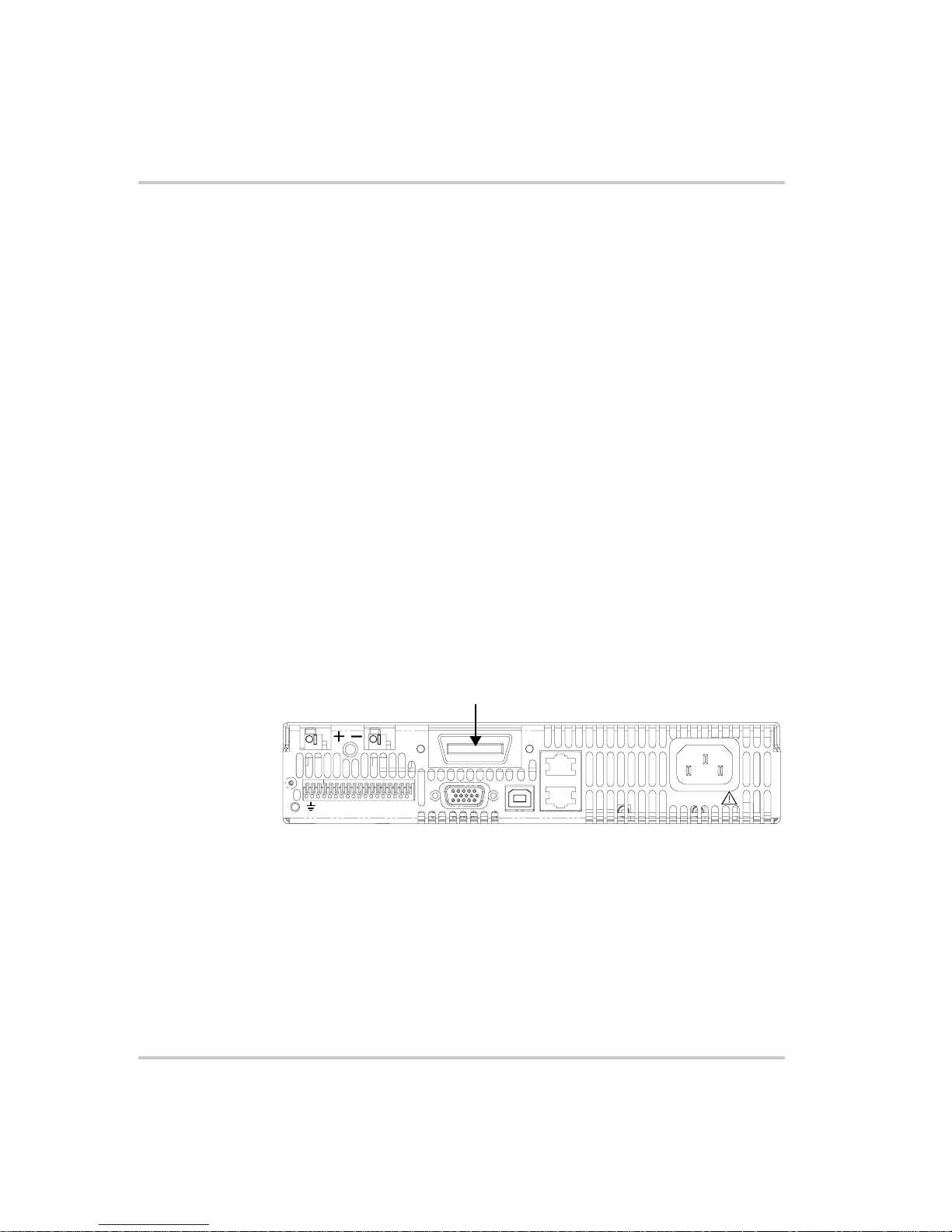
GPIB Pin Description
The GPIB port is a special GPIB female connector. See Figure 1-1.
GPIB Connector
J2
J3
SN
Figure 1-1
J1
GPIB Connector and Pins
1-2 M370046-06
J4
100-240 Vac
47-63 Hz, 11.5-6A
J5
J6
MADE IN CANADA
Page 17

Table 1-1 identifies the pin name and describes the pin functions.
Overview
Table 1-1
Pin # Name Function Note
1DIO1 DIO1 Data
2DIO2 DIO2 Data
3DIO3 DIO3 Data
4DIO4 DIO4 Data
5 EOI End of Identify Control
6 DAV Data Valid Handshake
7 NRFD Not Ready for Data Handshake
8 NDAC No Data Accepted Handshake
9 IFC Interface Clear Control
10 SRQ Service Request Control
11 ATN Attention Control
12 - Shield Chassis
13 DIO5 DIO5 Data
14 DIO6 DIO6 Data
15 DIO7 DIO7 Data
16 DIO8 DIO8 Data
17 REN Remote Enable Control
18 - DAV Return Chassis
19 - NRFD Return Chassis
20 - NDAC Return Chassis
21 - IFC Return Chassis
22 - SRQ Return Chassis
23 - ATN Return Chassis
24 - Signal Ground Chassis
GPIB Pin Description (J2)
M370046-06 1-3
Page 18

GPIB
Communication with Your Device
This section provides information on selecting the GPIB interface as the
communication port used on the XTR, and it also provides an example of
how commands can be sent and received. The details of the IEEE 488.2
and SCPI status reporting register structures and a complete list of
commands available can be found in the XTR 850 Watt Series
Programmable DC Power Supply Operating Manual.
Selecting a Communication Port
To select the GPIB as the communication port:
1. Turn the 9-Position Mode Control Knob to PGM.
rE is displayed in the output voltage display.
2. Turn the Rotary knob/Enter button to select the 6PIb communication
port.
3. Press the Rotary knob/Enter button.
ADDR is displayed on the output voltage display.
4. Turn the Rotary knob/Enter button to select the desired address
between 1 to 30. For the purpose of this example, 10 will be selected.
5. Press the Rotary knob/Enter button to commit the new address.
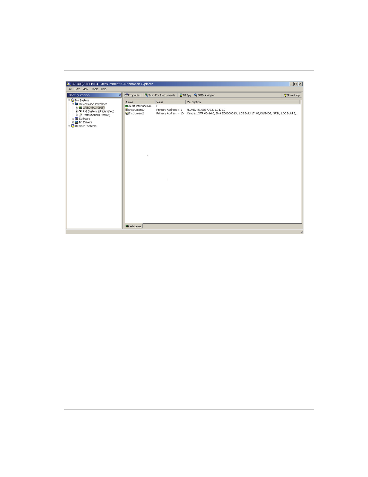
6. Click Scan For Instruments on the GPIB Explorer toolbar. See
Figure 1-2.
The power supply will be found as shown in Figure 1-2.
Important:
communicate with the XTR. This is for demonstration purposes only. Any
software that is capable of addressing a GPIB device and sending and receive
text could be used in its place. Consult your GPIB card manufacturer to see if
they provide an equivalent program.
1-4 M370046-06
This section uses the National Instruments™ MAX program to
Page 19
Communication with Your Device
:
Figure 1-2
Scanning for Instruments
7. In the right window, click on Instrument1 and review the device
properties. See Figure 1-3.
M370046-06 1-5
Page 20
GPIB
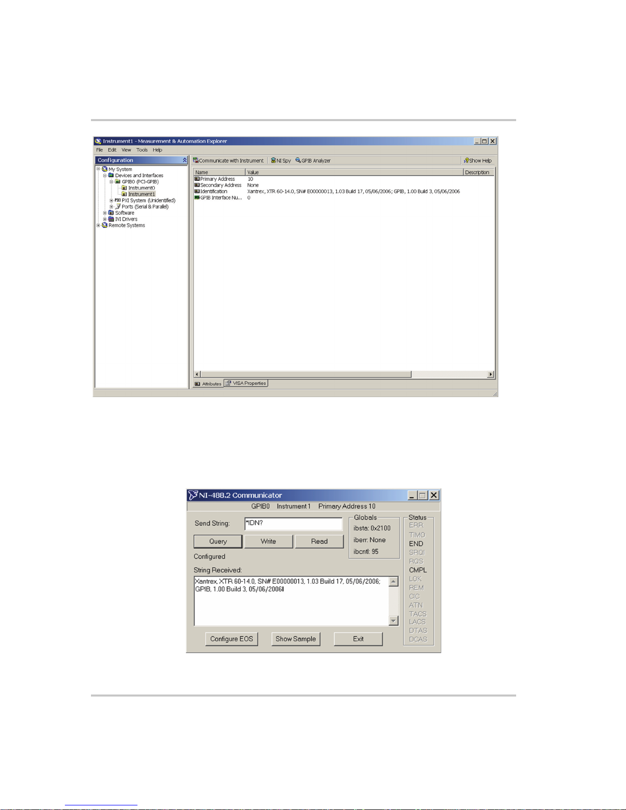
Figure 1-3
Instrument Properties
8. Click Communicate with Instrument in the GPIB Explorer toolbar.
See Figure 1-3.
NI-488.2 Communicator appears. See Figure 1-4.
Figure 1-4
1-6 M370046-06
ID String Query
Page 21

Communication with Your Device
9. In the Send String box, enter *IDN? and click Query.
Important:
Communicator program will exit.
If you press Enter while typing the string to be sent, the NI-488.2
10. The String Received window will show the ID string for the XTR.
The ID string indicates the model, serial number, firmware version as
well as the GPIB card firmware version. This will be shown in the
text box below String Received. See Figure 1-4.
M370046-06 1-7
Page 22

1-8
Page 23

2
Ethernet (ENET)
Chapter 2, “Ethernet (ENET)” provides information and
procedures to connect and configure the power supply to
the ENET.
Page 24

Ethernet (ENET)
Overview
This chapter is intended for network administrators responsible for the
configuration and maintenance of devices on the network. This chapter
provides information for connecting and configuring the power supply to
Ethernet.
Basic Section
This section describes the equipment and procedures to fully set up the
simplest configuration of an XTR unit with the ENET option and a single
computer.
Important:
Section” on page 2–25. Xantrex recommends that you read through this section
even if the configuration doesn't match your final setup.
System Requirements
• Windows XP, Windows 2000, Windows NT4.0 (with service pack
6.0a or later), Windows ME, or Windows 98
• Internet Explorer 5.01 or later
• 30 MB hard drive space
•64 MB RAM
Accessories
• Power supply with ENET port
• ENET RJ-45 and RJ-45 STP, Cat 5 cross-cable 9.84 feet (3 m) in
length or longer⑧
•PC
• Installation CD
Communication Cable
Use a standard RJ-45 (see Figure 2-1) and RJ-45 cross-cable (see
Figure 2-2).
The information in this section is applicable to the “Advanced
Figure 2-1
2-2 M370046-06
Computer or HUB Plug
Page 25

Basic Section
Figure 2-2
Figure 2-3
Table 2-1
Power Supply Plug
RJ-45 Plug
Description of PIN on RJ-45 Plug
Pin# Name Description
1 TX+ Transmit data +
2 TX– Transmit data –
3 RX+ Receive data +
4 Gnd Ground
5 Gnd Ground
6 RX– Receive data –
7 Gnd Ground
8 Gnd Ground
Figure 2-4
M370046-06 2-3
TX+
1
TX-
2
RX+
3
4
5
RX-
6
7
8
1
2
3
4
5
6
7
8
Scheme of ENET Cross-Cable
Page 26
Ethernet (ENET)
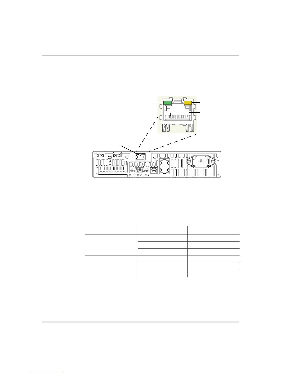
ENET Connector
The XPort® ENET connector is located on the rear panel of the power
supply. See Figure 2-5.
XPort™ LEDs
Left LED
Contact 8
XPort™ ENET connector
Figure 2-5
XPort® ENET Connector and LEDs
Right LED
Contact 1
The device contains two bi-color LEDs built into the front of the XPort™
connector. See Figure 2-5.
Table 2-2
LED Color Description
Link LED (Left side) Off No link
Activity LED (Right
side)
Description of LEDs
Amber 10 Mbps
Green 100 Mbps
Off No activity
Amber Half-duplex
Green Full-duplex
2-4 M370046-06
Page 27
Network Topology and Connection
The following section describes the network topology for the single
computer and single XTR power supply unit. The other possible network
topologies will be discussed later in the “Advanced Section” on page 2–
25. The additional topologies build on the configuration ideas present in
this section by referencing the various setup instructions.
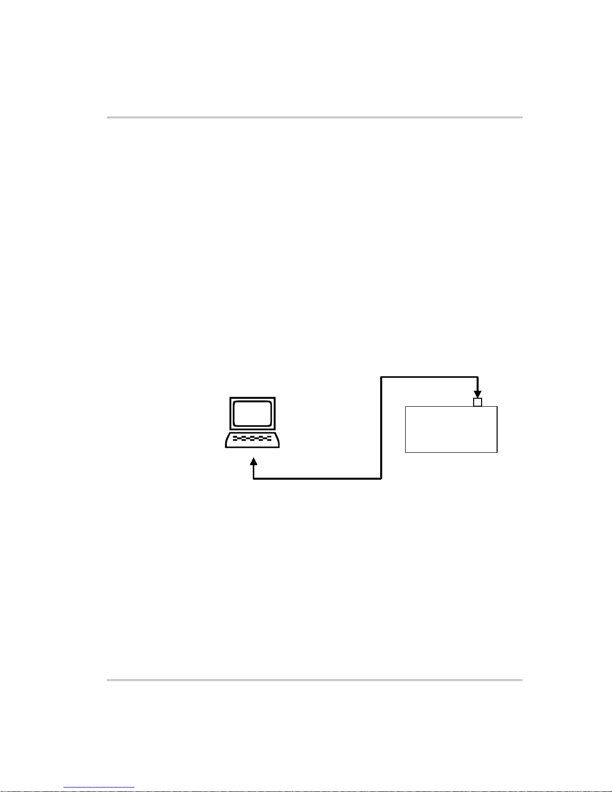
Single Computer and Single Power Supply Unit
Figure 2-6 shows the connection between the ENET unit and Local
Computer through a crossover cable; however, a HUB could also be used
with straight through Ethernet cables as well. Connect your computer to
the ENET as shown in Figure 2-6, or if this topology does not match your
configuration, refer to the “Advanced Section” on page 2–25 to identify
the topology you wish to implement and follow the instructions described
in that section.
Local Computer
Basic Section
ENET
Power Supply
Figure 2-6
M370046-06 2-5
Single Computer, Single Power Supply
Page 28

Ethernet (ENET)
Setting Up the Computer
To set up the computer:
1. Open Explorer on the main computer, go to Control Panel >
Network Connections > Local Area connections. See Figure 2-7.
o
Figure 2-7
Configuring the Network Connection of the Computer
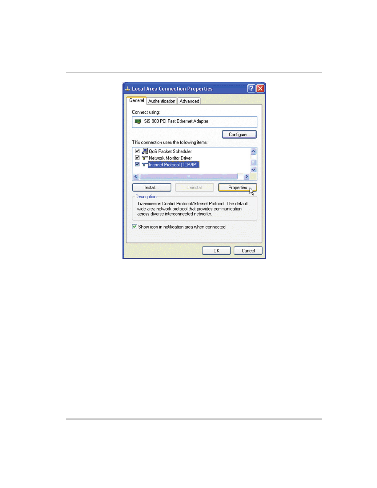
2. Right click on the mouse button and click on Properties.
The Local Area Connection Properties window appears. See
Figure 2-8.
2-6 M370046-06
Page 29
Basic Section
Figure 2-8
LAN Properties Dialog Box
3. Click the Internet Protocol (TCP/IP) check box and click Properties.
See Figure 2-8.
The Internet Protocol (TCP/IP) Properties Dialog Box appears. See
Figure 2-9.
M370046-06 2-7
Page 30
Ethernet (ENET)
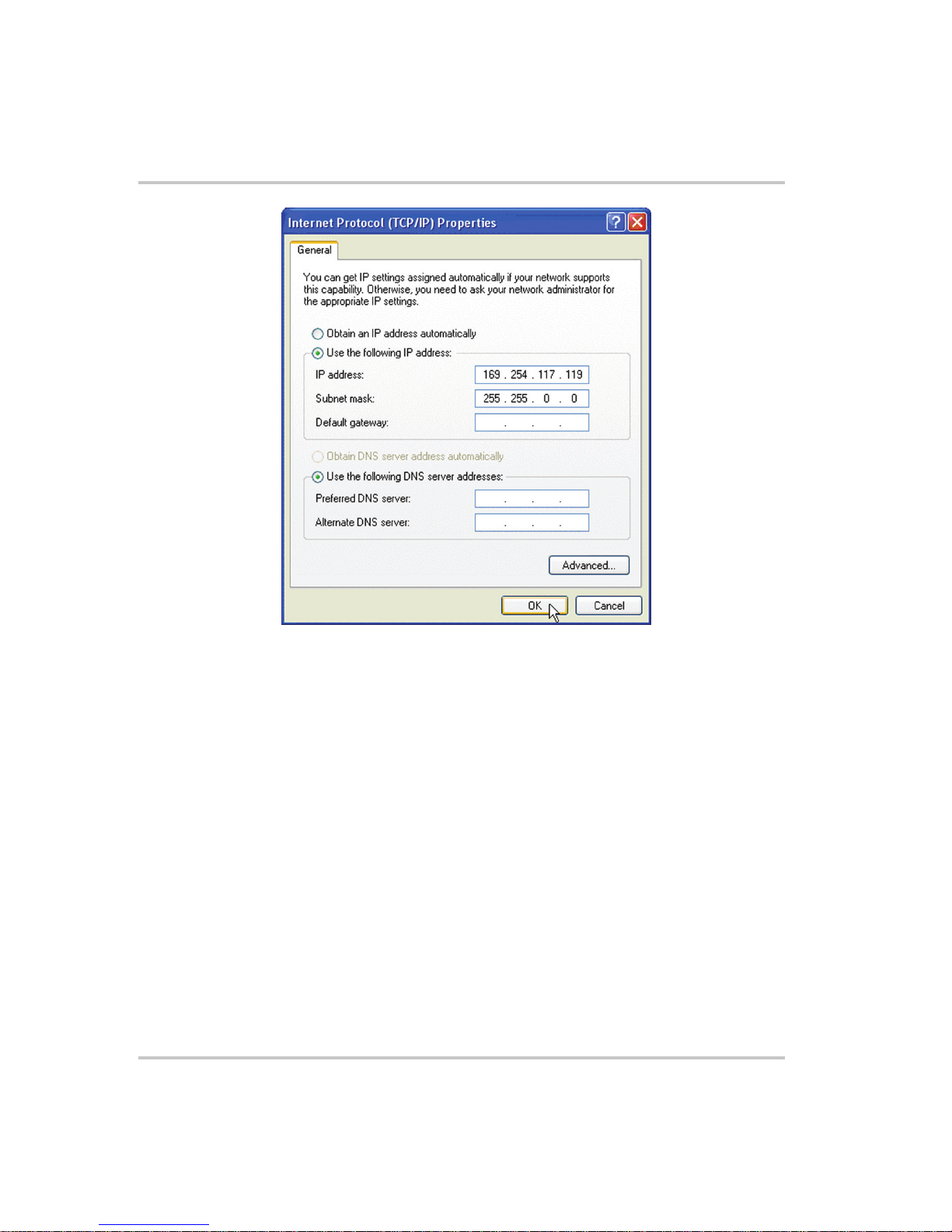
Figure 2-9
Internet Protocol (TCP/IP) Properties Dialog Box
4. Click on Use the following IP address option and type the
appropriate IP address in the box, or select the Obtain an IP address
automatically setting if your network is configured using DHCP.
5. Click OK.
2-8 M370046-06
Page 31
Software Installations
To set up the ENET option card, the Lantronix® DeviceInstaller program
needs to be installed on your PC. DeviceInstaller is an all-in-one utility
for setting up various Lantronix devices on a network. Device Installer
auto detects any devices on the network and allows for configuration of
network settings. As a management tool, the DeviceInstaller allows for
device monitoring and status verification of the ENET option card.
To install the DeviceInstaller:
1. Insert the DeviceInstaller CD into the CD ROM drive.
The CD should launch automatically.
If you need to manually launch the CD, click the Start button on the
Task Bar and select Run. Enter the CD drive letter, for example,
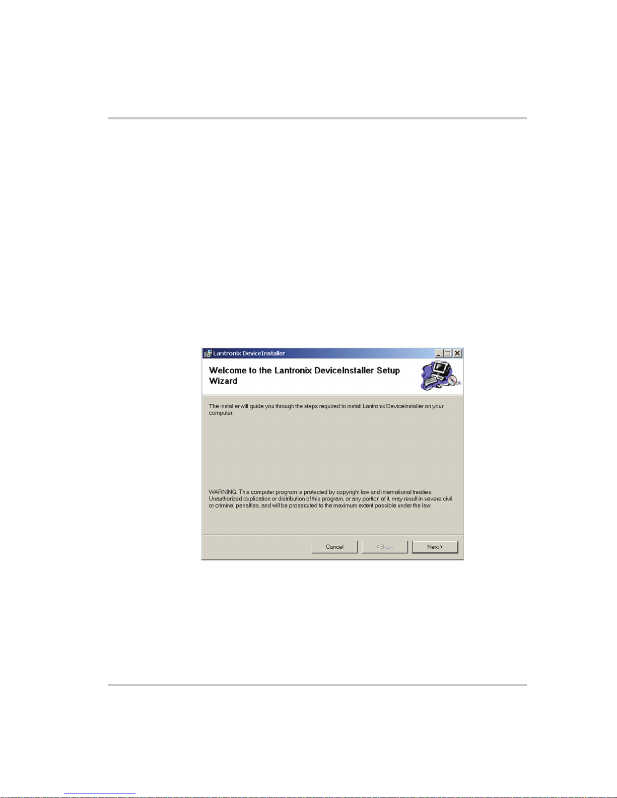
D:\Launch.exe. The DeviceInstaller Setup Wizard opens to guide the
installation process. See Figure 2-10.
Basic Section
Figure 2-10
2. Click Next to open the Select Installation Folder window.
M370046-06 2-9
DeviceInstaller Setup Wizard
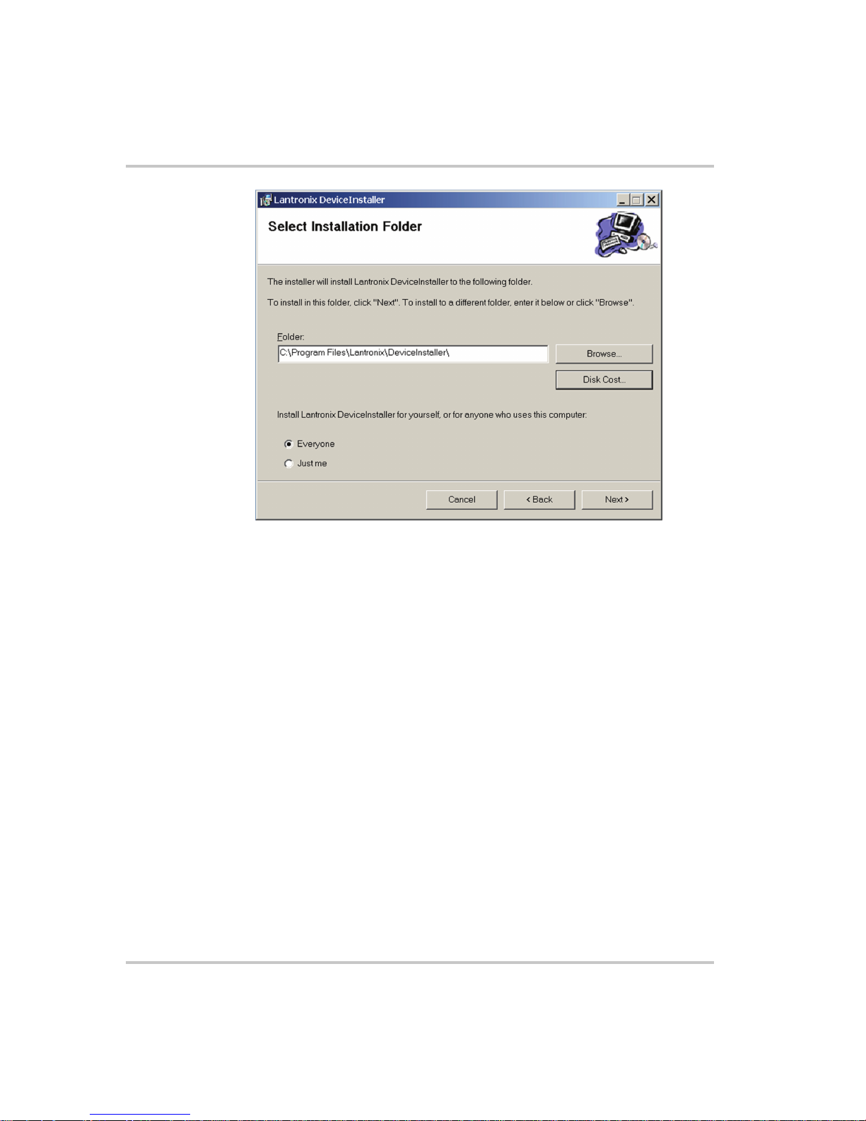
The Select Installation Folder window prompts for a destination
folder for the installation.
Page 32
Ethernet (ENET)
Figure 2-11
Select Installation Folder Window
3. Click Next to begin the installation.
The Installation Complete window displays when the installation is
finished.
6. Click Close to exit.
2-10 M370046-06
Page 33

Configuring the Device Using DeviceInstaller
Configuring the Device Using DeviceInstaller
The DeviceInstaller displays a list of the XTR units with the ENET option
that are on the network. When the DeviceInstaller initially starts, the
device list is empty. Devices may be added by performing a search for the
devices on the network or by adding them manually.
Selecting a Network Adapter
After the installation of DeviceInstaller to your PC, you must select which
network adaptor you wish the DeviceInstaller to use for all its network
communications.
To select the network adaptor:
1. Start DeviceInstaller by clicking Start > All Programs > Lantronix
> DeviceInstaller > DeviceInstaller.
2. If this is the first time you have started the program after installing it
and there are more than one network adaptors on the PC, you might
be prompted to select the network adaptor as seen in Figure 2-12. If
this prompt does not appear, click Tools > Options... to bring up the
dialog shown in Figure 2-13.
3. Verify that the network adaptor that is connected to the network that
you are running your XTR unit (s) on is selected.
Important:
cable connected will be shown in this list. If one of your networks adaptors is not
shown in this list, verify that it is enabled and has a network cable connected to it.
4. Click the OK button.
Figure 2-12
M370046-06 2-11
Only network adaptors that are enabled and have an Ethernet
Multiple Network Adapters
Page 34
Ethernet (ENET)
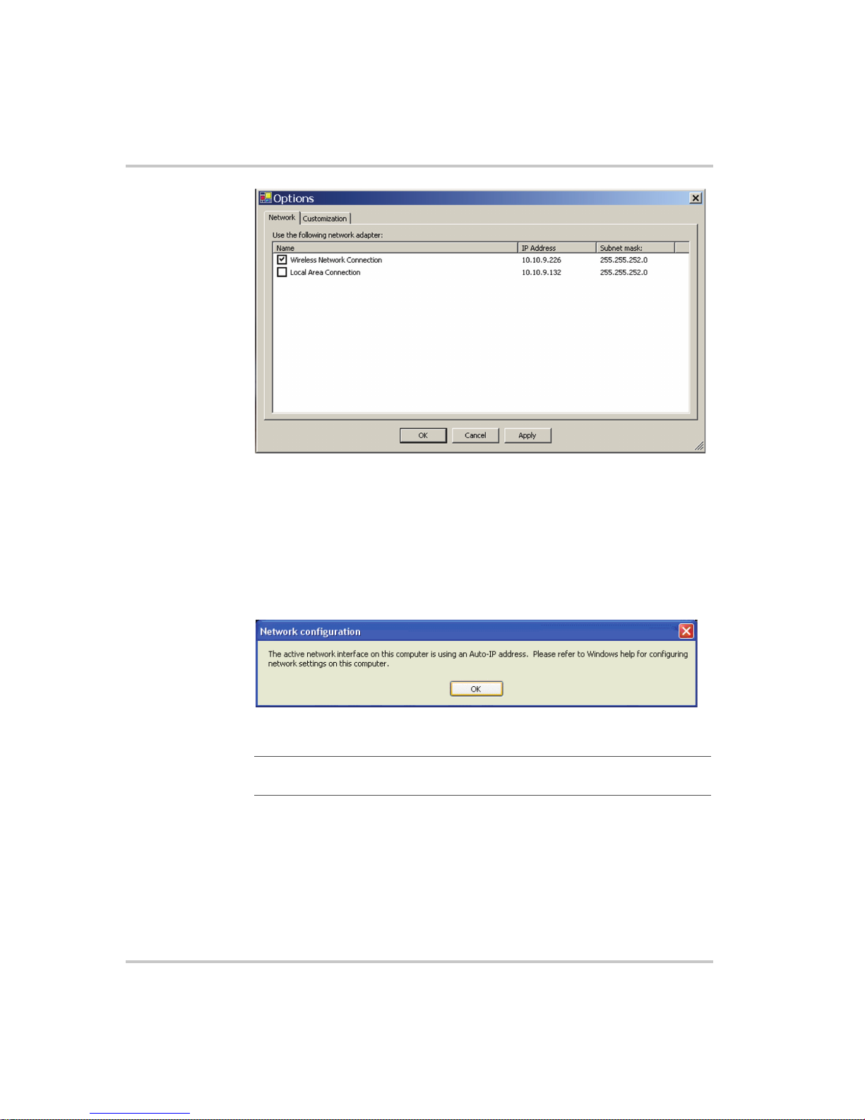
Figure 2-13
Selecting Network Adapter
Assigning an IP Address to the Power Supply Unit
If your system is auto-IP configured, the following warning message is
displayed:
Figure 2-14
Important:
single power supply configuration.
To assign an IP address to the power supply unit:
1. Click OK to dismiss the Auto-IP warning message. If you are not
intending on using an Auto-IP, debug your network connection at this
time.
Auto-IP Address Message
Auto-IP mode is acceptable only for the single computer and
The Lantronix DeviceInstaller window appears. See Figure 2-15.
2-12 M370046-06
Page 35
Configuring the Device Using DeviceInstaller
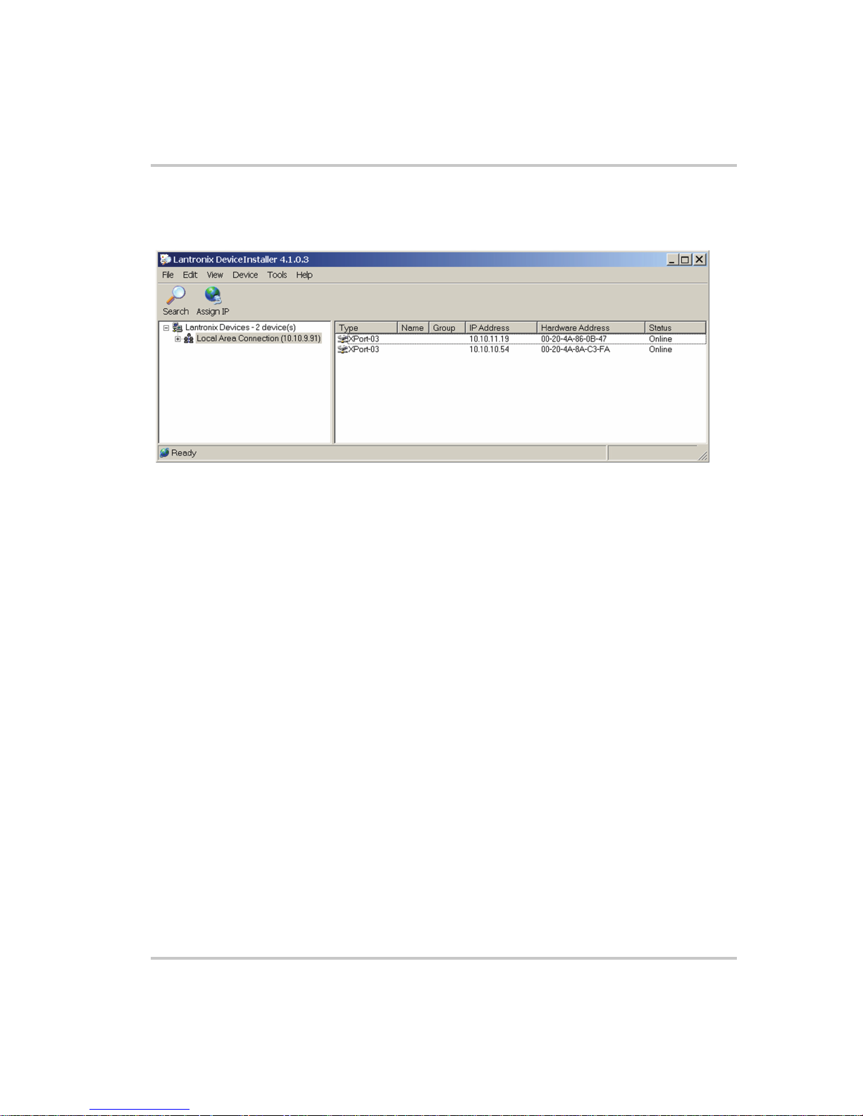
2. Click Search to get a list of the all the XTR devices that can be
reached from the network adaptor that you previously selected. If
your XTR unit (s) are powered up, they should appear in this list.
Figure 2-15
Searching for Power Supply IP Address
After a short delay, your power supply will be found. See
Figure 2-15. If the power supply is not found or the found device is
not reachable, contact your network administrator for details about
network settings.
3. If the IP address shown and the method that the XTR unit is using to
obtain this address is correct, go to step 13. Otherwise, continue with
step 4.
4. Click on the Assign IP icon and the Assign IP Address window
appears. See Figure 2-16.
M370046-06 2-13
Page 36

Ethernet (ENET)
Figure 2-16
Assign IP Address Window
5. In the Device Identification box, type the XPort® MAC address of
your power supply.
6. Refer to the XPort® cover or to documentation of your power supply
for the correct device MAC address. See Figure 2-17.
Figure 2-17
XPort® Label
7. Click Next.
8. Select the Assign a specific IP address option. See Figure 2-18.
2-14 M370046-06
Page 37

Configuring the Device Using DeviceInstaller
Figure 2-18
Assign IP Address Window
9. Click Next.
10. In the IP address field, enter the appropriate IP address for the
device. See Figure 2-19.
Figure 2-19
M370046-06 2-15
Assigning IP Settings
Page 38

Ethernet (ENET)
11. Click Next and in the next window, click Assign. See Figure 2-20.
Figure 2-21
Figure 2-20
IP Address Assignment
12. You may choose to close this window by clicking Cancel. Wait while
the device is rebooted.
13. Repeat this procedure for every power supply. Every device must
have a unique fixed IP address. See Figure 2-21.
Obtaining Power Supply IP Address
14. Save the obtained IP address for use later in the setup process.
2-16 M370046-06
Page 39

Configuring the Device Using DeviceInstaller
Selecting ENET as the Communication Port
Once the XTR unit with the ENET option has the option card configured,
you’ll need to configure the XTR to use the ENET option card as the
active communication port.
To select ENET as the communication port:
1. Turn the 9-Position Mode Control Knob to PGM.
rE is displayed in the output voltage display.
2. Turn the Rotary knob/Enter button to select the LAn communication
port.
3. Press the Rotary knob/Enter button.
ADDR is displayed on the output voltage display.
4. Turn the Rotary knob/Enter button to select the desired address
between 1 to 30.
5. Press the Rotary knob/Enter button to commit the new address.
M370046-06 2-17
Page 40

Ethernet (ENET)
Terminal Configuration
The terminal program allows for communication with the power supply.
To use a terminal program, set it up using the parameters from the
following sections. If you wish to use HyperTerminal, see “Setting Up a
HyperTerminal Connection” for instructions.
Data Format
Serial data format is 8 bit, one stop bit. No parity bit. Flow control: none.
End of Message
The end of message is the Carriage Return character (ASCII 13,
0x0D).The power supply ignores the Line Feed (ASCII 10, 0x0A)
character.
Setting Up a HyperTerminal Connection
To set up a HyperTerminal connection:
1. Start Windows HyperTerminal by clicking Start >All Program
>Accessories > Communications > HyperTerminal.
See Figure 2-22.
Figure 2-22
2-18 M370046-06
HyperTerminal Connection
Page 41
Terminal Configuration
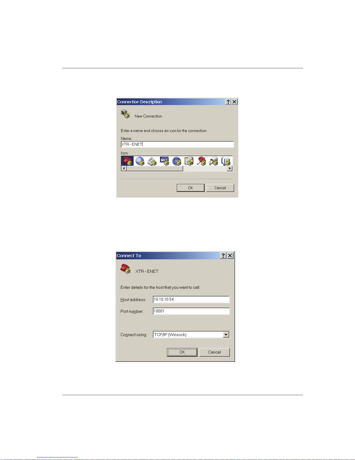
2. Click New to create a new connection.
The Connection Description window appears. See Figure 2-23.
Figure 2-23
Connection Description Window
3. Enter the name of the connection and select the icon.
4. Click OK.
The new connection setup dialog box will appear. See Figure 2-24.
Figure 2-24
New Connection Dialog Box
M370046-06 2-19
Page 42

Ethernet (ENET)
5. In the Connect using: box, select “TCP/IP (Winsock)”.
6. In the Host address box, enter the IP address, obtained in step 14 of
the section entitled “Assigning an IP Address to the Power Supply
Unit” on page 2–12.
7. In the Port number box, enter “10001” as the value.
8. Click OK.
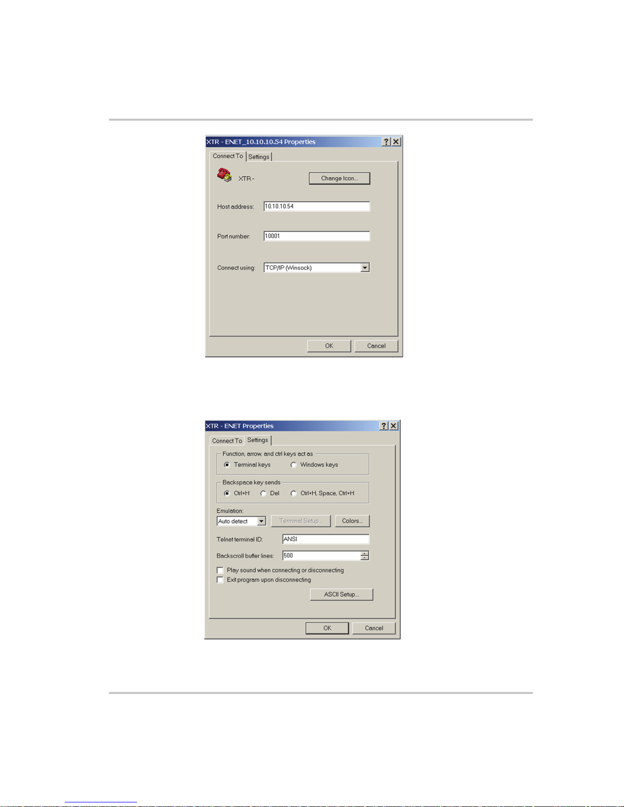
To specify the terminal connection properties:
1. Click Disconnect if necessary, and click Properties in the main
HyperTerminal window. See Figure 2-25.
Figure 2-25
2. In the ENET Properties window, click on the Settings tab. See
Figure 2-26.
2-20 M370046-06
Main Terminal Window
Page 43
Terminal Configuration
Figure 2-26
ENET Properties Window
The XTR-ENET Properties dialog box appears. See Figure 2-27.
Figure 2-27
XTR-ENET Properties Dialog Box
M370046-06 2-21
Page 44

Ethernet (ENET)
3. Click the ASCII Setup button.
The ASCII Setup dialog box will appear as shown in Figure 2-28.
4. Verify that the ASCII Sending and ASCII Receiving boxes are
checked as shown in Figure 2-28.
Figure 2-28
ASCII Setup Dialog Box
5. Click OK.
Establishing Communication with the Power Supply
To establish communication with the power supply:
1. In the main HyperTerminal window, click Call. See Figure 2-29.
2. To verify that the XTR unit is connected and functioning, type the
following command "*ADR <#>;*IDN?" where the
be replaced by the address assigned to the power supply in the
“Selecting ENET as the Communication Port” on page 2–17.
3. Verify that the XTR unit responds with the ID string.
4. To save your session for future use, click File > Save As….
See Figure 2-30.
2-22 M370046-06
<#> should
Page 45

Terminal Configuration
Figure 2-29
Figure 2-30
Main HyperTerminal Window
Saving Session
M370046-06 2-23
Page 46

Ethernet (ENET)
5. Type the name of the session. It is recommended that you include the
IP in your naming convention so that it is clear which XTR you are
connecting to.
6. Click Save.
Figure 2-31
Saved Session
Congratulations! Your network is installed and functioning properly.
2-24 M370046-06
Page 47

Advanced Section
Advanced Section
The advanced section describes the setup and connection for various
network topologies involving multiple power supplies.
Network Topology 1: Simple LAN
The simple LAN topology is the most common configuration for setting
up the ENET option on the XTR. The topology follows the typical star
topology provided by a HUB and multiple XTRs with the ENET option
and one or more computers. Figure 2-32 shows this configuration.
Local Computer #1 Local Computer #2
HUB
Power Supply #1
Figure 2-32
ENET
ENET
Power Supply #2
Multiple Power Supplies and Two Computers
Power Supply #30
ENET
All devices connects via the HUB. Every device must have a unique IP
address, for example:
• Computer #1: 169.254.117.231
• Computer #2: 169.254.117.232
• Power supply #1: 169.254.117.220
• Power supply #2: 169.254.117.221
• Power supply #3: 169.254.117.222
• Power supply #30: 169.254.117.230.
You must set up every device manually.
M370046-06 2-25
Page 48

Ethernet (ENET)
To set up for multiple power supplies and two computers:
1. Set up your computer as described in “Setting Up the Computer” on
page 2–6. Repeat the procedure for each computer hooked up to the
system.
2. Install the DeviceInstaller software on the PC you wish to use to
configure the XTR unit (s) with. See the instructions for “Software
Installations” on page 2–9.
3. Configure each XTR unit with an ENET option. See the instructions
for “Configuring the Device Using DeviceInstaller” on page 2–11
4. Create terminal connections for each of the XTR unit (s) with the
ENET option that were configured in step 3. See the instructions for
“Terminal Configuration” on page 2–18.
5. If more than one computer is going to be used, copy the filename.ht
files saved in step 3 to a disk and copy them over to each computer
that you will be using to access the XTR unit (s) over the Ethernet. If
copying the files is not possible, repeat step 3 for each computer that
you wish to use.
The configuration is complete. You are now ready to use your system.
Controlling Your System
For every connected XTR unit, create a separate terminal session. This
should have been done according to the instructions in “Establishing
Communication with the Power Supply” on page 2–22. Also, open a
separate HyperTerminal session for each XTR unit that you wish to
control. An example of two XTR units in a system is shown in
Figure 2-33.
2-26 M370046-06
Page 49

Advanced Section
Figure 2-33
HyperTerminal Session
There are two HyperTerminal windows for controlling two power supply
units. See Figure 2-33.
M370046-06 2-27
Page 50

Ethernet (ENET)
Figure 2-34
Figure 2-34 shows a system with two connected devices.
Important:
IP address, whereas the address defined from front panel (power supply’s own
address) may be arbitrary.
2-28 M370046-06
System with Two Connected Devices
In this system configuration, every power supply needs a unique
Page 51

Network Topology 2: ENET and RS-485 Bus
Up to 30 units may be connected to the RS-485 bus. The first unit
connects to the controller via ENET, and the other units are connected
with the RS-485 bus.
Figure 2-35 shows the system of an XTR unit with the ENET option and
several XTR units connected via the RS-485 bus. Each power supply
must have its own address, defined from the front panel. Only one IP
address is required for your network (excluding computers) and only one
controlling program is required (one per XTR with ENET option as noted
in “Network Topology 1: Simple LAN” on page 2–25).
Local Computer
ENET
RS-485
RS-485
Advanced Section
IN OUT IN OUT IN OUT
Power Supply #1
Figure 2-35
M370046-06 2-29
ENET and RS-485 Bus
Power Supply #2
Power Supply #30
Page 52

Ethernet (ENET)
Figure 2-36
HyperTerminal Window
Figure 2-36 shows the HyperTerminal session for the combined
configuration which is an ENET and RS-485 network. This figure also
shows access to power supplies #2 and #10 sequentially.
Setting Up Your System
To set up your system:
1. Connect your system as shown in Figure 2-35, and turn every power
supply unit to ON.
2. Set up your computer as described in “Setting Up the Computer” on
page 2–6. Repeat this section for each computer hooked up to the
system.
3. Install the DeviceInstaller software on the PC you wish to use to
configure the XTR unit (s) with. See the instructions for “Software
Installations” on page 2–9.
4. Configure the ENET card of the master XTR (power supply #1 in
Figure 2-35). See the instructions for “Configuring the Device Using
DeviceInstaller” on page 2–11.
2-30 M370046-06
Page 53

Advanced Section
5. Configure the master power supply which is the unit with the ENET
option (power supply #1 in Figure 2-35) by following the instructions
in “Selecting ENET as the Communication Port” on page 2–17.
6. The following Steps 7, 8 and 9 must be repeated for each slave unit.
7. For the slave unit that you are setting up, turn the 9-Position Mode
Control Knob to PGM.
rE is displayed in the output voltage display.
8. Turn the Rotary knob/Enter button to select SLA and press the Rotary
knob/Enter button.
9. Set a unique address and press the Rotary knob/Enter button. See the
XTR 850 Watt Series Programmable DC Power Supply Operating
Manual (Part number: M370046-01), Chapter 5, “Multichannel
Address Setting” section for a more detailed discussion of addressing.
Once all slave units have been setup, proceed with the next step.
10. Set up the fixed IP address for the first unit using DeviceInstaller as
described in “Assigning an IP Address to the Power Supply Unit” on
page 2–12.
11. Create and set up a new HyperTerminal session as described in
“Terminal Configuration” on page 2–18.
12. In the HyperTerminal session window, type the *ADR <#>;*IDN?
command where the <#> should be replaced by the address assigned
to the power supply in step 9. Press enter to send the command.
13. Verify that the unit responds with the ID string. Perform this test for
each unit that is connected including the master unit.
14. If additional XTR units are using Network Topology 2, repeat the
setup procedure steps 1 to 14 for each ENET and RS-485 group.
Important:
but the RS-485 bus addresses can be reused for each unique ENET – RS-485
group.
M370046-06 2-31
The IP address for each ENET and RS-485 group must be unique,
Page 54

2-32
Page 55

A
Troubleshooting
Appendix A, “Troubleshooting” provides troubleshooting
information for the combined ENET and RS-485
communication and for ENET communication.
Page 56

Troubleshooting
Troubleshooting for ENET – RS-485 Communication
This section describes specific troubleshooting for the combined
ENET – RS-485 communication only.
See “Troubleshooting for ENET Communication” on page A–3 for
typical troubleshooting procedures for connecting and setting up ENET
communications.
Table A-1
Symptom Check Action
One of the power supply units
is not responding.
Sequentially several units are
not responding, e.g. from #21
to end.
All of the units are not
responding.
Troubleshooting for ENET – RS-485 Communication
The power supply is not turned
on.
The communication interface is
not set as a slave unit (RS-485) or
the address has not been set
correctly.
RS-485 communication is
disconnected at the first unit that
is not responding.
The ENET communication is
disconnected.
The HyperTerminal session is not
configured properly.
Turn the power supply ON.
Check that the RS-485 bus is
selected as the communication
interface and the address is
correct.
Check your RS-485
communication. Try switching the
cable linking this unit to the last
unit that is known to have given a
response.
Check the ENET communication.
Check the settings of the
HyperTerminal session. Follow
the instructions in the “Selecting
ENET as the Communication
Port” on page 2–17.
A-2 M370046-06
Page 57

Troubleshooting for ENET Communication
This section describes typical troubleshooting for connecting and setting up
the ENET communication.
Table A-2
Symptom Check Action
DeviceInstaller does not
detect your device.
Troubleshooting for ENET Communication
Your ENET cable is not a cross
cable.
Power supply is not turned on.
The network that your computer is
on cannot reach the network that
the XTR with the ENET option is
connected to.
DeviceInstaller is not configured to
use the Ethernet card on your
computer that is connected to the
network which has the XTR with
ENET option on it.
Use the correct ENET cross cable.
Turn the power supply ON.
Connect a laptop to the HUB or to
the switch that the XTR with the
ENET option is connected to, and
ping the computer you are trying
to use DeviceInstaller on. If no
response is seen, then contact your
network administrator and find
out if ICMP requests are being
filtered on the network and a
possible reason for not being able
to contact the computer.
See “Selecting a Network
Adapter” on page 2–11.
Found device is not
reachable.
Typed text is not visible. Echo mode is not active. Select Echo typed characters
M370046-06 A-3
Your network is not configured
properly.
Contact your network
administrator.
locally in the ASCII Setup dialog
box of HyperTerminal.
Page 58

Troubleshooting
Table A-2
The power supply is not
responding.
Troubleshooting for ENET Communication
The communication port on the
power supply unit is not selected
properly.
The address of the power supply
unit is not valid. The address has
not been selected using the
<address>
.
*ADR
Select “ENET” as the
communication port.
Refer to the correct power supply
address using the front panel.
See the
XTR 850 Watt Series
Programmable DC Power Supply
Operating Manual (Part number:
M370046-01), Chapter 5: Remote
Interface Addressing for a detailed
explanation on how to use the
*ADR command.
A-4 M370046-06
Page 59

B
Links
Appendix B, “Links” provides the Web site links for
relevant third party vendors.
Page 60

Links
Links
Lantronix, Inc. Web site www.lantronix.com/index.html
XPort™ Embedded Device Server www.lantronix.com/products/eds/xport/
index.html
XPort™ latest utilities and firmware | DeviceInstaller | http://
www.lantronix.com/device-networking/
utilities-tools/device-installer.html |
XPort™ Installer | DeviceInstaller | http://
www.lantronix.com/device-networking/
utilities-tools/device-installer.html |
Java virtual machine http://java.sun.com/j2se/downloads.html
B-2 M370046-06
Page 61

Warranty and Return Information
Warranty
What does this warranty cover? This Limited Warranty is provided by Xantrex Technology Inc.
("Xantrex") and covers defects in workmanship and materials in your XTR 850W GPIB and Ethernet
Interface Option. This warranty period lasts for five (5) years from the date of purchase at the point of
sale to you, the original end user customer. You require proof of purchase to make warranty claims.
What will Xantrex do? Xantrex will, at its option, repair or replace the defective product free of
charge, provided that you notify Xantrex of the product defect within the Warranty Period, and provided
that Xantrex through inspection establishes the existence of such a defect and that it is covered by this
Limited Warranty.
Xantrex will, at its option, use new and/or reconditioned parts in performing warranty repair and
building replacement products. Xantrex reserves the right to use parts or products of original or
improved design in the repair or replacement. If Xantrex repairs or replaces a product, its warranty
continues for the remaining portion of the original Warranty Period or 90 days from the date of the
return shipment to the customer, whichever is greater. All replaced products and all parts removed from
repaired products become the property of Xantrex.
Xantrex covers both parts and labor necessary to repair the product, and return shipment to the customer
via a Xantrex-selected non-expedited surface freight within the contiguous United States and Canada.
Alaska and Hawaii are excluded. Contact Xantrex Customer Service for details on freight policy for
return shipments outside of the contiguous United States and Canada.
How do you get service? If your product requires troubleshooting or warranty service, contact your
merchant. If you are unable to contact your merchant, or the merchant is unable to provide service,
contact Xantrex directly at:
Telephone: 1 800 733 5427 (toll free North America)
1 858 450 0085 (direct)
Fax: 1 858 678 4482 (direct)
Email: prg.info@xantrex.com
Direct returns may be performed according to the Xantrex Return Material Authorization Policy
described in your product manual. For some products, Xantrex maintains a network of regional
Authorized Service Centers. Call Xantrex or check our website to see if your product can be repaired at
one of these facilities.
M370046-06 WA-1
Page 62

Warranty and Return
What proof of purchase is required? In any warranty claim, dated proof of purchase must
accompany the product and the product must not have been disassembled or modified without prior
written authorization by Xantrex.
Proof of purchase may be in any one of the following forms:
• The dated purchase receipt from the original purchase of the product at point of sale to the end user,
or
• The dated dealer invoice or purchase receipt showing original equipment manufacturer (OEM)
status, or
• The dated invoice or purchase receipt showing the product exchanged under warranty
What does this warranty not cover? This Limited Warranty does not cover normal wear and tear
of the product or costs related to the removal, installation, or troubleshooting of the customer's electrical
systems. This warranty does not apply to and Xantrex will not be responsible for any defect in or
damage to:
a) the product if it has been misused, neglected, improperly installed, physically damaged or altered,
either internally or externally, or damaged from improper use or use in an unsuitable environment;
b) the product if it has been subjected to fire, water, generalized corrosion, biological infestations, or
input voltage that creates operating conditions beyond the maximum or minimum limits listed in
the Xantrex product specifications including high input voltage from generators and lightning
strikes;
c) the product if repairs have been done to it other than by Xantrex or its authorized service centers
(hereafter "ASCs");
d) the product if it is used as a component part of a product expressly warranted by another
manufacturer;
e) the product if its original identification (trade-mark, serial number) markings have been defaced,
altered, or removed.
Disclaimer
Product
THIS LIMITED WARRANTY IS THE SOLE AND EXCLUSIVE WARRANTY PROVIDED BY XANTREX IN
CONNECTION WITH YOUR XANTREX PRODUCT AND IS, WHERE PERMITTED BY LAW, IN LIEU OF ALL OTHER
WARRANTIES, CONDITIONS, GUARANTEES, REPRESENTATIONS, OBLIGATIONS AND LIABILITIES, EXPRESS OR
IMPLIED, STATUTORY OR OTHERWISE IN CONNECTION WITH THE PRODUCT, HOWEVER ARISING (WHETHER
BY CONTRACT, TORT, NEGLIGENCE, PRINCIPLES OF MANUFACTURER'S LIABILITY, OPERATION OF LAW,
CONDUCT, STATEMENT OR OTHERWISE), INCLUDING WITHOUT RESTRICTION ANY IMPLIED WARRANTY OR
CONDITION OF QUALITY, MERCHANTABILITY OR FITNESS FOR A PARTICULAR PURPOSE. ANY IMPLIED
WARRANTY OF MERCHANTABILITY OR FITNESS FOR A PARTICULAR PURPOSE TO THE EXTENT REQUIRED
UNDER APPLICABLE LAW TO APPLY TO THE PRODUCT SHALL BE LIMITED IN DURATION TO THE PERIOD
STIPULATED UNDER THIS LIMITED WARRANTY.
IN NO EVENT WILL XANTREX BE LIABLE FOR ANY SPECIAL, INDIRECT, INCIDENTAL OR CONSEQUENTIAL
DAMAGES, LOSSES, COSTS OR EXPENSES HOWEVER ARISING WHETHER IN CONTRACT OR TORT INCLUDING
WITHOUT RESTRICTION ANY ECONOMIC LOSSES OF ANY KIND, ANY LOSS OR DAMAGE TO PROPERTY, ANY
PERSONAL INJURY, ANY DAMAGE OR INJURY ARISING FROM OR AS A RESULT OF MISUSE OR ABUSE, OR THE
INCORRECT INSTALLATION, INTEGRATION OR OPERATION OF THE PRODUCT.
WA-2 M370046-06
Page 63

Warranty and Return
Exclusions
If this product is a consumer product, federal law does not allow an exclusion of implied warranties. To
the extent you are entitled to implied warranties under federal law, to the extent permitted by applicable
law they are limited to the duration of this Limited Warranty. Some states and provinces do not allow
limitations or exclusions on implied warranties or on the duration of an implied warranty or on the
limitation or exclusion of incidental or consequential damages, so the above limitation(s) or
exclusion(s) may not apply to you. This Limited Warranty gives you specific legal rights. You may have
other rights which may vary from state to state or province to province.
Return Material Authorization Policy
Before returning a product directly to Xantrex you must obtain a Return Material Authorization (RMA)
number and the correct factory "Ship To" address. Products must also be shipped prepaid. Product
shipments will be refused and returned at your expense if they are unauthorized, returned without an
RMA number clearly marked on the outside of the shipping box, if they are shipped collect, or if they
are shipped to the wrong location.
When you contact Xantrex to obtain service, please have your instruction manual ready for reference
and be prepared to supply:
• The serial number of your product
• Information about the installation and use of the unit
• Information about the failure and/or reason for the return
• A copy of your dated proof of purchase
Record these details in “Information About Your System” on page WA–4.
M370046-06 WA-3
Page 64

Warranty and Return
Return Procedure
1. Package the unit safely, preferably using the original box and packing materials. Please ensure that
your product is shipped fully insured in the original packaging or equivalent. This warranty will not
apply where the product is damaged due to improper packaging.
2. Include the following:
• The RMA number supplied by Xantrex Technology Inc. clearly marked on the outside of the
box.
• A return address where the unit can be shipped. Post office boxes are not acceptable.
• A contact telephone number where you can be reached during work hours.
• A brief description of the problem.
3. Ship the unit prepaid to the address provided by your Xantrex customer service representative.
If you are returning a product from outside of the USA or Canada In addition to the above,
you MUST include return freight funds and are fully responsible for all documents, duties, tariffs, and
deposits.
If you are returning a product to a Xantrex Authorized Service Center (ASC) A Xantrex
return material authorization (RMA) number is not required. However, you must contact the ASC prior
to returning the product or presenting the unit to verify any return procedures that may apply to that
particular facility.
Out of Warranty Service
If the warranty period for your XTR 850W GPIB and Ethernet Interface Option has expired, if the unit
was damaged by misuse or incorrect installation, if other conditions of the warranty have not been met,
or if no dated proof of purchase is available, your unit may be serviced or replaced for a flat fee.
To return your XTR 850W GPIB and Ethernet Interface Option for out of warranty service, contact
Xantrex Customer Service for a Return Material Authorization (RMA) number and follow the other
steps outlined in “Return Procedure” on page WA–4.
Payment options such as credit card or money order will be explained by the Customer Service
Representative. In cases where the minimum flat fee does not apply, as with incomplete units or units
with excessive damage, an additional fee will be charged. If applicable, you will be contacted by
Customer Service once your unit has been received.
Information About Your System
As soon as you open your XTR 850W GPIB and Ethernet Interface Option package, record the
following information and be sure to keep your proof of purchase.
❐ Serial Number
❐ Product Number
❐ Purchased From
❐ Purchase Date
WA-4 M370046-06
_________________________________
FGA number. See “Product Numbers (FGAs)” on page ii.
_________________________________
Page 65

Page 66

Xantrex Technology Inc.
1 800 733 5427 (toll free North America)
1 858 450 0085 (direct)
1 858 678 4482 (direct)
prg.info@xantrex.com
www.xantrex.com
M370046-06
Printed in USA
 Loading...