

XTR 6-110 XTR 6-220
XTR 8-100 XTR 8-200
XTR 12-70 XTR 12-140
XTR 20-42 XTR 20-84
XTR 33-25 XTR 33-50
XTR 40-21 XTR 40-42
XTR 60-14 XTR 60-28
XTR 80-10.5 XTR 80-21
XTR 100-8.5 XTR 100-17
XTR 150-5.6 XTR 150-11.2
XTR 300-2.8 XTR 300- 5.6
XTR 600-1.4 XTR 600-2.8
Operating Manual
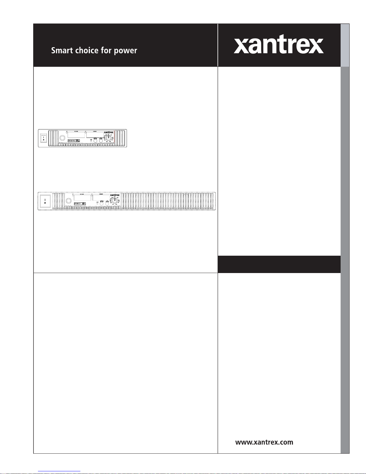
XTR 850 Watt and
1700 Watt Series
Programmable DC
Power Supply


XTR 850 Watt and 1700
Watt Series Programmable
DC Power Supply
Operating Manual

About Xantrex
Xantrex Technology Inc. is a world-leading supplier of advanced power electronics and controls with
products from 50 watt mobile units to 2.5 MW utility-scale systems for wind, solar, batteries, fuel cells,
microturbines, and backup power applications in both grid-connected and stand-alone systems. Xantrex
products include inverters, battery chargers, programmable power supplies, and variable speed drives
that convert, supply , control, clean, and distribute electrical power.
Trademarks
XTR 850 Watt and 1700 Watt Series Programmable DC Power Supply is a trademark of Xantrex
International. Xantrex is a registered trademark of Xantrex International.
Other trademarks, registered trademarks, and product names are the property of their respective owners
and are used herein for identification purposes only.
Notice of Copyright
XTR 850 Watt and 170 0 Watt Series Programmable DC Power Supply Operating Manual© April 2006
Xantrex International. All rights reserved.
Exclusion for Documentation
UNLESS SPECIFICALLY AGREED TO IN WRITING, XANTREX TECHNOLOGY INC.
(“XANTREX”)
(A) MAKES NO WARRANTY AS TO THE ACCURACY, SUFFICIENCY OR SUITABILITY OF
ANY TECHNICAL OR OTHER INFORMATION PROVIDED IN ITS MANUALS OR OTHER
DOCUMENTATION.
(B) ASSUMES NO RESPONSIBILITY OR LIABILITY FOR LOSSES, DAMAGES, COSTS OR
EXPENSES, WHETHER SPECIAL, DIRECT, INDIRECT, CONSEQUENTIAL OR INCIDENTAL,
WHICH MIGHT ARISE OUT OF THE USE OF SUCH INFORMATION. THE USE OF ANY SUCH
INFORMATION WILL BE ENTIRELY AT THE USER’S RISK; AND
(C) REMINDS YOU THAT IF THIS MANUAL IS IN ANY LANGUAGE OTHER THAN
ENGLISH, ALTHOUGH STEPS HAVE BEEN TAKEN TO MAINTAIN THE ACCURACY OF THE
TRANSLATION, THE ACCURACY CANNOT BE GUARANTEED. APPROVED XANTREX
CONTENT IS CONTAINED WITH THE ENGLISH LANGUAGE VERSION WHICH IS POSTED
AT WWW.XANTREX.COM.
Date and Revision
April 2006 Revision A
Part Number
975-0200-01-01
975-0200-01-01 ii

Product Numbers (FGAs)
850 Watt Models 1700 Watt Models
XTR_6-110 XTR_6-220
XTR_8-100 XTR_8-200
XTR_12-70 XTR_12-140
XTR_20-42 XTR_20-84
XTR_33-25 XTR_33-50
XTR_40-21 XTR_40-42
XTR_60-14 XTR_60-28
XTR_80-10.5 XTR_80-21
XTR_100-8.5 XTR_100-17
XTR_150-5.6 XTR_150-11
XTR_300-2.8
XTR_600-1.4
XTR_300-5.6
XTR_600-2.8
Part Numbers for Rack Mount Kits
Rack Mount Kit Part Number
Dual XTR 850 Watt RM-D-XTR1
Single XTR 850 W att RM-S-XTR1
Rack mount rails for
XTR 1700 Watt Series
RM-XFR
Contact Information
Telephone: 1 800 667 8422 (toll free North America)
1 360 925 5097 (direct)
Fax: 1 360 925 5143
Email: customerservice@xantrex.com
Web: www.xantrex.com
975-0200-01-01 iii

About This Manual
Purpose
The Operating Manual provides installation and operating information for
the XTR 850 Watt and 1700 Watt Series Programmable DC Power Supply.
Scope
The Manual provides safety information, features and specifications,
installation procedures, functional test procedures, and operating procedures
for both local (front panel) operation and remote operation.
The Manual does not provide information on the GPIB and Ethernet
(ENET) interface options. See the XTR 850W and 1700W GPIB and
Ethernet Interface Option Operating Manual.
Audience
The Manual is intended for the user who is familiar with electronic power
supplies, Constant Voltage and Constant Current operating modes, and the
control of output power. The user should be familiar with practicing safe
techniques while making supply or pin connections.
Conventions Used
The following conventions are used in this guide.
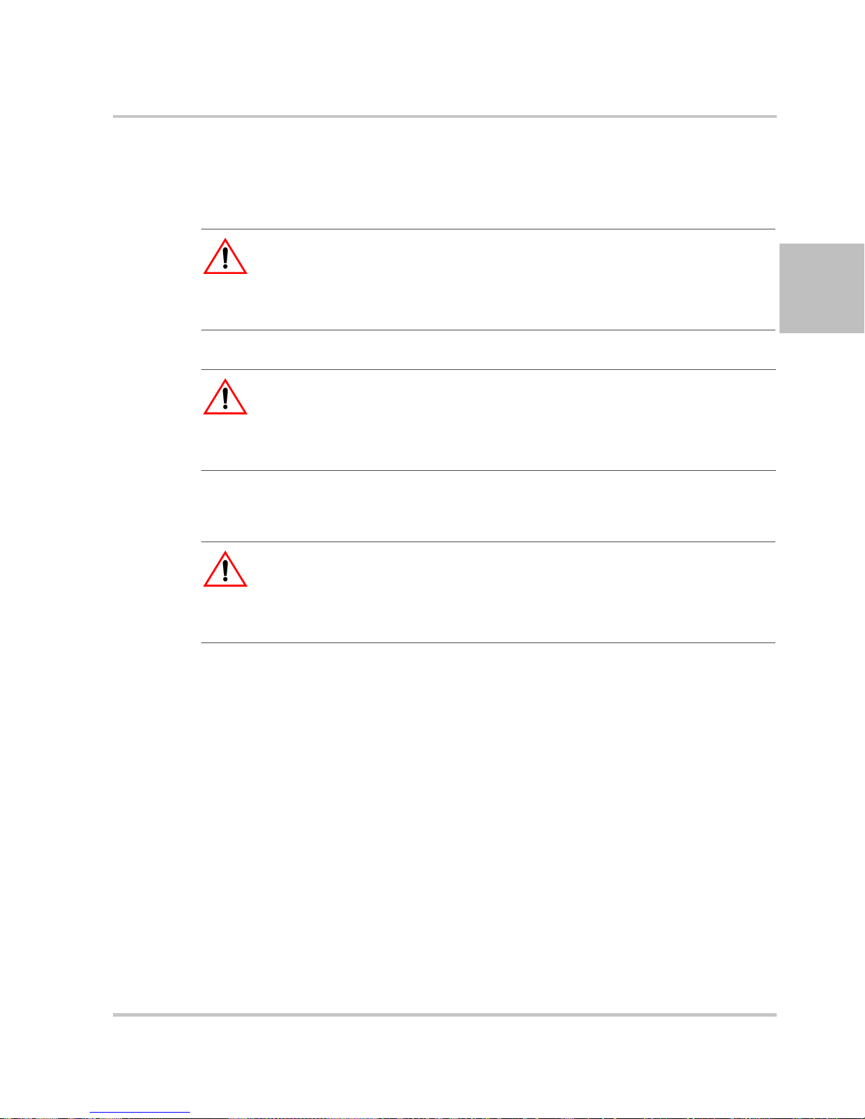
WARNING
Wa rnings identify conditions or practices that could result in personal injury or
loss of life.
CAUTION
Cautions identify conditions or practices that could result in damage to the unit or
other equipment.
Important:
know . They are not as serious as Warnings or Cautions.
975-0200-01-01 v
Important notes provide information that is important for you to

About This Manual
Related Information
For related information on this product, see also:
• XTR 850W and 1700W GPIB and Ethernet Interface Option
Operating Manual provides information on the GPIB and Ethernet
interface option. (Part number 975-0275-0101)
• XTR 850 Watt and 1700 Watt Series Programmable DC Power
Supply: Quick Reference Guide is included with your power supply
and provides an introduction to using the front panel interface. (Part
number 975-0276-01-01)
• Rack Mount Kit Options Installation Instructions provides
information on rack mounting a single or dual XTR 850 Watt (part
number 975-0281-01-01) or XTR 1700 Watt unit. (Part number 9750282-01-01)
More information about Xantrex Technology Inc. as well as its products
and services is available at
Acronyms
www.xantrex.com.
Acronym Definition
APG Analog Programming
AUX Auxiliary
ENET Ethernet
ISOL Isolated Analog Programming
OTP Over Temperature Protection
OVP Over Voltage Protection
PSU Power Supply Unit
TVS Transient Voltage Suppressor
UVP Under Voltage Protection
Font Conventions
This Manual uses the following typographical conventions:
7 segment
For display and readback information on the
output voltage and current displays.
Command body text
vi 975-0200-01-01
Represents SCPI commands.
Important Safety Instructions
WARNING: High energy and high voltage
Exercise caution when using a power supply. High energy levels can be stored at
the output voltage terminals on a power supply in normal operation. In addition,
potentially lethal voltages exist in the power circuit and on the output and sense
connectors of a power supply with a rated output greater than 40
capacitors store potentially dangerous energy for some time after power is
removed.
WARNING
Operate the power supply in an environment free of flammable gases or fumes.
To ensure that the power supply's safety features are not compromised, use the
power supply as specified in this Manual and do not substitute parts or make any
unauthorized modifications. If service is necessary, please return the power
supply to the Authorized Service Center. See
Policy” on page WA–3.
WARNING: Limitations on use
The XTR 850 W att and 1700 Watt Series Programmable DC Power Supply is not
intended for use in connection with life support systems or other medical
equipment or devices.
“Return Material Authorization
V. Filter
CAUTION: For use as a battery charger
When you are using a power supply for battery charging applications, it is
essential to provide an appropriately sized fuse or circuit breaker in series
between the power supply output and the battery.
Installation of a protector (fuse or DC circuit breaker), rated for about 115% of
the maximum current rating of the power supply and designed specifically to
interrupt the DC voltage of the battery, will provide adequate current protection.
Where several power supplies are in parallel, it is best to fuse each power supply
rather than use one fuse at the battery.
Power Supply Safety Markings
Alternating Current On (Supply)
Earth (Ground) Terminal Off (Supply)
Protective Conductor
Terminal
975-0200-01-01 vii
Caution (Check the Manual
for additional information.)

Safety
Standard Warnings
WARNING
This chapter contains important safety and operating instructions. Read and keep
this Operating Manual for future reference.
1. Before installing and using the XTR 850 Watt or XTR 1700 Watt
Series Programmable DC Power Supply, read all instructions and
cautionary markings on the XTR and all appropriate sections of this
Manual.
2. The XTR is for indoor use only. Do not expose the XTR to moisture.
To reduce risk of fire hazard, do not cover or obstruct the ventilation
openings. Be sure to install the XTR in a compartment which allows
air to reach the ventilation inlets on the front and rear of the unit to
prevent overheating. For more information, see
page 2–4.
“Ventilation” on
3. To avoid a risk of fire and electric shock, make sure that the existing
wiring is in good condition and the wire is not undersized. Do not
operate the XTR with damaged or substandard wiring.
4. Do not operate the XTR if it has received a sharp blow, been dropped,
or otherwise damaged in any way. If the XTR is damaged, see
“Warranty and Product Information” on page WA–1.
5. Do not disassemble the XTR. It contains no user-serviceable parts.
See the
instructions on obtaining service. Attempting to service the XTR
yourself may result in a risk of electrical shock or fire. Internal
capacitors remain charged after all power is disconnected.
6. To reduce the risk of electrical shock, disconnect AC power from the
XTR before attempting any maintenance or cleaning or working on
any circuits connected to the XTR. Turning off controls will not
reduce this risk.
“Warranty and Product Information” on page WA–1 for
viii 975-0200-01-01

Contents
Important Safety Instructions
1
Introduction
Features and Options - - - - - - - - - - - - - - - - - - - - - - - - - - - - - - - - - - - - - - - - - - -1–2
XTR 850 Watt and XTR 1700 Watt Models- - - - - - - - - - - - - - - - - - - - - - - - - - - -1–3
Front Panel for XTR 850 Watt and XTR 1700 Watt - - - - - - - - - - - - - - - - - - - - - -1–4
Front Panel Display and Controls - - - - - - - - - - - - - - - - - - - - - - - - - - - - - - - - 1–5
Rear Panel Connectors on XTR 850 Watt - - - - - - - - - - - - - - - - - - - - - - - - - - - - -1–6
Rear Panel Connectors on XTR 1700 Watt- - - - - - - - - - - - - - - - - - - - - - - - - - - - -1–8
2
Installation
Basic Setup Procedure - - - - - - - - - - - - - - - - - - - - - - - - - - - - - - - - - - - - - - - - - -2–2
Step 1: Inspecting and Cleaning - - - - - - - - - - - - - - - - - - - - - - - - - - - - - - - - - - - -2–3
Initial Inspection - - - - - - - - - - - - - - - - - - - - - - - - - - - - - - - - - - - - - - - - - - - -2–3
Periodic Cleaning - - - - - - - - - - - - - - - - - - - - - - - - - - - - - - - - - - - - - - - - - - -2–3
Step 2: Location and Mounting - - - - - - - - - - - - - - - - - - - - - - - - - - - - - - - - - - - -2–4
Rack Mounting - - - - - - - - - - - - - - - - - - - - - - - - - - - - - - - - - - - - - - - - - - - - 2–4
Purchasing Rack Mount Kits - - - - - - - - - - - - - - - - - - - - - - - - - - - - - - - - - - -2–4
Ventilation - - - - - - - - - - - - - - - - - - - - - - - - - - - - - - - - - - - - - - - - - - - - - - -2–4
Step 3: Connecting AC Input Power - - - - - - - - - - - - - - - - - - - - - - - - - - - - - - - - -2–5
XTR 850 Watt AC Input Connector - - - - - - - - - - - - - - - - - - - - - - - - - - - - - - -2–5
XTR 1700 Watt AC Input Connector - - - - - - - - - - - - - - - - - - - - - - - - - - - - - -2–6
XTR 1700 Watt AC Input Wire - - - - - - - - - - - - - - - - - - - - - - - - - - - - - - - - -2–7
XTR 1700 Watt AC Input Wire Connection - - - - - - - - - - - - - - - - - - - - - - - - -2–7
Step 4: Selecting Load Wires- - - - - - - - - - - - - - - - - - - - - - - - - - - - - - - - - - - - - -2–9
Load Wiring - - - - - - - - - - - - - - - - - - - - - - - - - - - - - - - - - - - - - - - - - - - - - - 2–9
Step 5: Performing Functional Tests - - - - - - - - - - - - - - - - - - - - - - - - - - - - - - - -2–11
Powering the Power Supply On/Off - - - - - - - - - - - - - - - - - - - - - - - - - - - - - -2–11
Voltage and Current Mode Operation Checks - - - - - - - - - - - - - - - - - - - - - - -2–12
Step 6: Connecting Loads - - - - - - - - - - - - - - - - - - - - - - - - - - - - - - - - - - - - - - -2–13
DC Output Connectors - - - - - - - - - - - - - - - - - - - - - - - - - - - - - - - - - - - - - -2–13
Inductive Loads - - - - - - - - - - - - - - - - - - - - - - - - - - - - - - - - - - - - - - - - - - -2–14
- - - - - - - - - - - - - - - - - - - - - - - - - - - - - - - - - vii
975-0200-01-01 ix

Connecting Single Loads - - - - - - - - - - - - - - - - - - - - - - - - - - - - - - - - - - - - -2–14
Connecting Multiple Loads - - - - - - - - - - - - - - - - - - - - - - - - - - - - - - - - - - -2–15
Step 7: Connecting Remote Sensing - - - - - - - - - - - - - - - - - - - - - - - - - - - - - - - -2–16
3
Local Operation
Introduction - - - - - - - - - - - - - - - - - - - - - - - - - - - - - - - - - - - - - - - - - - - - - - - - -3–2
Configuring Settings from the Front Panel - - - - - - - - - - - - - - - - - - - - - - - - - - - - -3–2
Using the 9-Position Mode Control Knob - - - - - - - - - - - - - - - - - - - - - - - - - - -3–2
Using the Rotary knob/Enter button - - - - - - - - - - - - - - - - - - - - - - - - - - - - - - -3–2
Coarse and Fine Adjustment Modes - - - - - - - - - - - - - - - - - - - - - - - - - - - - - - -3–2
Navigating the Menu System - - - - - - - - - - - - - - - - - - - - - - - - - - - - - - - - - - - - - -3–4
Setting VOL and CUR Modes - - - - - - - - - - - - - - - - - - - - - - - - - - - - - - - - - -3–4
Normal Display Mode and Inactivity Timeout - - - - - - - - - - - - - - - - - - - - - - - -3–6
Display Messages on the Front Panel - - - - - - - - - - - - - - - - - - - - - - - - - - - - - - - -3–8
Standard Operation- - - - - - - - - - - - - - - - - - - - - - - - - - - - - - - - - - - - - - - - - - - -3–10
Operating Modes - - - - - - - - - - - - - - - - - - - - - - - - - - - - - - - - - - - - - - - - - -3–10
Shipped Configuration (Local Operation) - - - - - - - - - - - - - - - - - - - - - - - - - -3–14
Turning the Output On/Off - - - - - - - - - - - - - - - - - - - - - - - - - - - - - - - - - - - - - -3–14
Turning the Auxiliary Output On/Off - - - - - - - - - - - - - - - - - - - - - - - - - - - - - - -3–15
Output Auto Start Mode (Auto Restart) - - - - - - - - - - - - - - - - - - - - - - - - - - - - - -3–15
Auxiliary Auto Start Mode - - - - - - - - - - - - - - - - - - - - - - - - - - - - - - - - - - - - - -3–16
Alarms and Errors - - - - - - - - - - - - - - - - - - - - - - - - - - - - - - - - - - - - - - - - - - - -3–17
Clearing Alarms - - - - - - - - - - - - - - - - - - - - - - - - - - - - - - - - - - - - - - - - - - -3–18
Front Panel ALARM LED - - - - - - - - - - - - - - - - - - - - - - - - - - - - - - - - - - - -3–19
Alarm Masking - - - - - - - - - - - - - - - - - - - - - - - - - - - - - - - - - - - - - - - - - - -3–20
Alarm Output Latching - - - - - - - - - - - - - - - - - - - - - - - - - - - - - - - - - - - - - -3–21
Setting Foldback Mode- - - - - - - - - - - - - - - - - - - - - - - - - - - - - - - - - - - - - - - - -3–22
Resetting Activated Foldback Protection - - - - - - - - - - - - - - - - - - - - - - - - - - 3–23
Using Over Voltage Protection (OVP)- - - - - - - - - - - - - - - - - - - - - - - - - - - - - - - 3–24
Defining the OVP Set Point - - - - - - - - - - - - - - - - - - - - - - - - - - - - - - - - - - -3–24
Using Under Voltage Protection (UVP)- - - - - - - - - - - - - - - - - - - - - - - - - - - - - -3–25
Defining the UVP Set Point - - - - - - - - - - - - - - - - - - - - - - - - - - - - - - - - - - -3–25
Over Current Protection (OCP) - - - - - - - - - - - - - - - - - - - - - - - - - - - - - - - - - - -3–25
Using Over Temperature Protection Lock (OTP) - - - - - - - - - - - - - - - - - - - - - - -3–26
Defining the OTP Mode - - - - - - - - - - - - - - - - - - - - - - - - - - - - - - - - - - - - -3–26
Resetting in Latch Mode - - - - - - - - - - - - - - - - - - - - - - - - - - - - - - - - - - - - -3–26
Contents
x 975-0200-01-01

Contents
Current Configuration Memory Settings - - - - - - - - - - - - - - - - - - - - - - - - - - - - -3–27
User Setting Memory Locations - - - - - - - - - - - - - - - - - - - - - - - - - - - - - - - - - - -3–28
Saving User Setting Memory Locations - - - - - - - - - - - - - - - - - - - - - - - - - - -3–28
Recalling User Setting Memory Locations - - - - - - - - - - - - - - - - - - - - - - - - -3–29
Local Lockout - - - - - - - - - - - - - - - - - - - - - - - - - - - - - - - - - - - - - - - - - - - - - - -3–30
Enabling Local Lockout - - - - - - - - - - - - - - - - - - - - - - - - - - - - - - - - - - - - - -3–30
Disabling Local Lockout - - - - - - - - - - - - - - - - - - - - - - - - - - - - - - - - - - - - -3–30
Using the External Shutdown Function - - - - - - - - - - - - - - - - - - - - - - - - - - - - - - 3–31
Activating the External Shutdown Function - - - - - - - - - - - - - - - - - - - - - - - -3–31
Controlling the External Shutdown Function - - - - - - - - - - - - - - - - - - - - - - - - 3–31
Defining the Polarity of the External Shutdown Signal - - - - - - - - - - - - - - - - - 3–31
Interlock Function - - - - - - - - - - - - - - - - - - - - - - - - - - - - - - - - - - - - - - - - - - - -3–33
Defining the Interlock Mode - - - - - - - - - - - - - - - - - - - - - - - - - - - - - - - - - - -3–33
Power On Status Signal - - - - - - - - - - - - - - - - - - - - - - - - - - - - - - - - - - - - - -3–33
Hardware Malfunction Alarms- - - - - - - - - - - - - - - - - - - - - - - - - - - - - - - - - - - -3–34
Resetting the Power Supply- - - - - - - - - - - - - - - - - - - - - - - - - - - - - - - - - - - - - -3–35
Using Multiple Power Supplies - - - - - - - - - - - - - - - - - - - - - - - - - - - - - - - - - - -3–37
Configuring Multiple Supplies for Series Operation - - - - - - - - - - - - - - - - - - -3–39
Configuring Multiple Supplies for Current Sharing Operation (APG Method) -3–41
Connecting to the Load in Local Sensing Mode (Parallel Control Method) - - - 3–43
Connecting to the Load in Remote Sensing Mode (Parallel Control Method) - - 3–44
4
Analog Programming (APG) and Isolated Analog Programming
(ISOL)
Introduction - - - - - - - - - - - - - - - - - - - - - - - - - - - - - - - - - - - - - - - - - - - - - - - - -4–2
Analog Programming (APG) of Output Voltage and Output Current - - - - - - - - -4–2
Remote Programming Options - - - - - - - - - - - - - - - - - - - - - - - - - - - - - - - - - -4–3
Analog Programming (APG) Connector J1 - - - - - - - - - - - - - - - - - - - - - - - - - -4–5
Analog Programming Mode- - - - - - - - - - - - - - - - - - - - - - - - - - - - - - - - - - - - - - -4–9
Analog Programming With External Voltage Source - - - - - - - - - - - - - - - - - - -4–9
Voltage-Controlled Voltage APG Setup - - - - - - - - - - - - - - - - - - - - - - - - - - -4–10
Voltage-Controlled Current APG Setup - - - - - - - - - - - - - - - - - - - - - - - - - - - 4–12
Resistive-Controlled Voltage APG Setup - - - - - - - - - - - - - - - - - - - - - - - - - -4–15
Resistive-Controlled Current APG Setup - - - - - - - - - - - - - - - - - - - - - - - - - -4–17
Voltage and Current Readback - - - - - - - - - - - - - - - - - - - - - - - - - - - - - - - - -4–18
Isolated Analog Programming Mode (ISOL) - - - - - - - - - - - - - - - - - - - - - - - - - -4–19
AUX Output and Isolated Analog Programming (ISOL) Connector - - - - - - - -4–19
xi 975-0200-01-01

Voltage-Controlled Voltage ISOL Setup - - - - - - - - - - - - - - - - - - - - - - - - - - 4–22
Voltage-Controlled Current ISOL Setup - - - - - - - - - - - - - - - - - - - - - - - - - - -4–23
Resistive-Controlled Voltage ISOL Setup - - - - - - - - - - - - - - - - - - - - - - - - - - 4–26
Resistive-Controlled Current ISOL Setup - - - - - - - - - - - - - - - - - - - - - - - - - -4–27
Voltage and Current Readback (Isolated)- - - - - - - - - - - - - - - - - - - - - - - - - - - - - 4–29
5
Remote Operation
Introduction - - - - - - - - - - - - - - - - - - - - - - - - - - - - - - - - - - - - - - - - - - - - - - - - -5–2
Hardware and Connection Setup- - - - - - - - - - - - - - - - - - - - - - - - - - - - - - - - - - - -5–2
Configuring Remote Control Using RS-232 - - - - - - - - - - - - - - - - - - - - - - - - -5–2
Configuring Remote Control Using RS-485 - - - - - - - - - - - - - - - - - - - - - - - - -5–7
Configuring Remote Control using the USB Connector - - - - - - - - - - - - - - - - -5–9
Setting Up the PC to Use the USB Connection - - - - - - - - - - - - - - - - - - - - - - -5–9
Ethernet (ENET) or GPIB Connector (Optional) - - - - - - - - - - - - - - - - - - - - - 5–14
Multiple Power Supply Connections to RS-485 Bus - - - - - - - - - - - - - - - - - - -5–15
Multiple Power Supply Connections to ENET - - - - - - - - - - - - - - - - - - - - - - - 5–16
Terminal Configuration- - - - - - - - - - - - - - - - - - - - - - - - - - - - - - - - - - - - - - - - -5–17
Data Format - - - - - - - - - - - - - - - - - - - - - - - - - - - - - - - - - - - - - - - - - - - - - -5–17
End of Message - - - - - - - - - - - - - - - - - - - - - - - - - - - - - - - - - - - - - - - - - - -5–17
HyperTerminal - - - - - - - - - - - - - - - - - - - - - - - - - - - - - - - - - - - - - - - - - - - -5–17
Selecting the Appropriate Communication Port - - - - - - - - - - - - - - - - - - - - - -5–20
Multichannel Address Setting - - - - - - - - - - - - - - - - - - - - - - - - - - - - - - - - - -5–21
Remote Interface Addressing - - - - - - - - - - - - - - - - - - - - - - - - - - - - - - - - - - 5–21
Multichannel Commands Explained - - - - - - - - - - - - - - - - - - - - - - - - - - - - - 5–22
Status Reporting in SCPI - - - - - - - - - - - - - - - - - - - - - - - - - - - - - - - - - - - - -5–23
Status Registers Model from IEEE 488.2- - - - - - - - - - - - - - - - - - - - - - - - - - - - - 5–25
Status Byte - - - - - - - - - - - - - - - - - - - - - - - - - - - - - - - - - - - - - - - - - - - - - - - - -5–26
Error/Event Queue (ERR) - - - - - - - - - - - - - - - - - - - - - - - - - - - - - - - - - - - -5–26
Questionable Status Register Summary (QSR) - - - - - - - - - - - - - - - - - - - - - -5–26
Message Available (MAV) - - - - - - - - - - - - - - - - - - - - - - - - - - - - - - - - - - - -5–27
Standard Event Status Summary (ESB) - - - - - - - - - - - - - - - - - - - - - - - - - - -5–27
Master Summary Status (MSS) - - - - - - - - - - - - - - - - - - - - - - - - - - - - - - - - -5–27
Request Service (RQS) - - - - - - - - - - - - - - - - - - - - - - - - - - - - - - - - - - - - - -5–27
Operation Status Register Summary (OSR) - - - - - - - - - - - - - - - - - - - - - - - - -5–27
Standard Event Status Register (SESR) - - - - - - - - - - - - - - - - - - - - - - - - - - -5–29
Contents
xii 975-0200-01-01

Contents
Standard SCPI Register Structure - - - - - - - - - - - - - - - - - - - - - - - - - - - - - - - - - - 5–32
OPERation Status Register - - - - - - - - - - - - - - - - - - - - - - - - - - - - - - - - - - - - - -5–33
Current SHare Sub-Register - - - - - - - - - - - - - - - - - - - - - - - - - - - - - - - - - - -5–35
Operation Status Register Commands - - - - - - - - - - - - - - - - - - - - - - - - - - - -5–36
Current Sharing Sub-Register Commands - - - - - - - - - - - - - - - - - - - - - - - - - -5–37
Shutdown Sub-Register Commands - - - - - - - - - - - - - - - - - - - - - - - - - - - - - -5–38
Protection Sub-Register Commands - - - - - - - - - - - - - - - - - - - - - - - - - - - - - -5–39
QUEStionable Status Register - - - - - - - - - - - - - - - - - - - - - - - - - - - - - - - - - - - - 5–40
VOLTage Sub-Register - - - - - - - - - - - - - - - - - - - - - - - - - - - - - - - - - - - - - -5–42
TEMPerature Sub-Register - - - - - - - - - - - - - - - - - - - - - - - - - - - - - - - - - - -5–43
Questionable Status Register Commands - - - - - - - - - - - - - - - - - - - - - - - - - -5–43
Voltage Status Register Commands - - - - - - - - - - - - - - - - - - - - - - - - - - - - - - 5–44
Temperature Status Register Commands - - - - - - - - - - - - - - - - - - - - - - - - - - 5–45
SCPI Error/Event Queue - - - - - - - - - - - - - - - - - - - - - - - - - - - - - - - - - - - - - - - -5–46
Reset Command - - - - - - - - - - - - - - - - - - - - - - - - - - - - - - - - - - - - - - - - - - - 5–48
Clear All Status Registers - - - - - - - - - - - - - - - - - - - - - - - - - - - - - - - - - - - -5–49
SCPI Preset Status - - - - - - - - - - - - - - - - - - - - - - - - - - - - - - - - - - - - - - - - -5–49
Command Line Help System - - - - - - - - - - - - - - - - - - - - - - - - - - - - - - - - - -5–50
Locking and Unlocking the Front Panel- - - - - - - - - - - - - - - - - - - - - - - - - - - - - - 5–55
Auto Sequence Programming - - - - - - - - - - - - - - - - - - - - - - - - - - - - - - - - - -5–55
Configure Other Protection Mechanisms - - - - - - - - - - - - - - - - - - - - - - - - - - - - - 5–62
Foldback Protection - - - - - - - - - - - - - - - - - - - - - - - - - - - - - - - - - - - - - - - -5–62
Over Temperature Protection - - - - - - - - - - - - - - - - - - - - - - - - - - - - - - - - - - 5–63
Interlock Enable/Disable - - - - - - - - - - - - - - - - - - - - - - - - - - - - - - - - - - - - -5–63
Save and Recall - - - - - - - - - - - - - - - - - - - - - - - - - - - - - - - - - - - - - - - - - - -5–64
Set Analog Programming Level - - - - - - - - - - - - - - - - - - - - - - - - - - - - - - - -5–64
Set Remote Programming Interface - - - - - - - - - - - - - - - - - - - - - - - - - - - - - -5–65
Protection Mask (Enable Alarms) - - - - - - - - - - - - - - - - - - - - - - - - - - - - - - -5–65
6
Calibration and Troubleshooting
Introduction - - - - - - - - - - - - - - - - - - - - - - - - - - - - - - - - - - - - - - - - - - - - - - - - -6–2
Main Voltage and Current Calibration Principle - - - - - - - - - - - - - - - - - - - - - - - - -6–2
Understanding the Problem - - - - - - - - - - - - - - - - - - - - - - - - - - - - - - - - - - - -6–2
Step 1: Gain Calibration - - - - - - - - - - - - - - - - - - - - - - - - - - - - - - - - - - - - - - 6–3
Step 2: Offset Calibration - - - - - - - - - - - - - - - - - - - - - - - - - - - - - - - - - - - - - -6–4
Step 3: Recalibrate Gain - - - - - - - - - - - - - - - - - - - - - - - - - - - - - - - - - - - - - -6–4
xiii 975-0200-01-01

Contents
Calibrating the Output Voltage- - - - - - - - - - - - - - - - - - - - - - - - - - - - - - - - - - - - -6–5
Gain Calibration - - - - - - - - - - - - - - - - - - - - - - - - - - - - - - - - - - - - - - - - - - - -6–5
Offset Calibration - - - - - - - - - - - - - - - - - - - - - - - - - - - - - - - - - - - - - - - - - - -6–5
Calibrating the Output Current- - - - - - - - - - - - - - - - - - - - - - - - - - - - - - - - - - - - -6–6
Gain Calibration - - - - - - - - - - - - - - - - - - - - - - - - - - - - - - - - - - - - - - - - - - - -6–6
Offset Calibration - - - - - - - - - - - - - - - - - - - - - - - - - - - - - - - - - - - - - - - - - - -6–6
Over Voltage Protection Calibration - - - - - - - - - - - - - - - - - - - - - - - - - - - - - - - - -6–7
Non-isolated Analog Programming Calibration- - - - - - - - - - - - - - - - - - - - - - - - - -6–8
Non-isolated Voltage Monitoring Calibration - - - - - - - - - - - - - - - - - - - - - - - -6–8
Non-isolated Current Monitoring Calibration - - - - - - - - - - - - - - - - - - - - - - - -6–9
Non-isolated Voltage Programming of Voltage Calibration - - - - - - - - - - - - - - -6–9
Non-isolated Resistive Programming of Voltage Calibration - - - - - - - - - - - - - 6–10
Non-isolated Voltage Programming of Current Calibration - - - - - - - - - - - - - -6–11
Non-isolated Resistive Programming of Current Calibration - - - - - - - - - - - - - 6–11
Calibration Procedure for Isolated Modes - - - - - - - - - - - - - - - - - - - - - - - - - - - -6–13
Isolated Voltage Monitoring Calibration - - - - - - - - - - - - - - - - - - - - - - - - - - -6–13
Isolated Current Monitoring Calibration - - - - - - - - - - - - - - - - - - - - - - - - - - -6–13
Isolated Voltage Programming of Voltage Calibration - - - - - - - - - - - - - - - - - 6–14
Isolated Resistive Programming of Voltage Calibration - - - - - - - - - - - - - - - - 6–15
Isolated Voltage Programming of Current Calibration - - - - - - - - - - - - - - - - - 6–16
Isolated Resistive Programming of Current Calibration - - - - - - - - - - - - - - - - -6–16
Storing and Loading Calibration Parameters- - - - - - - - - - - - - - - - - - - - - - - - - - - 6–17
Restore Factory Calibration - - - - - - - - - - - - - - - - - - - - - - - - - - - - - - - - - - - - - -6–18
User Diagnostics - - - - - - - - - - - - - - - - - - - - - - - - - - - - - - - - - - - - - - - - - - - - -6–18
Emergency Shutdown - - - - - - - - - - - - - - - - - - - - - - - - - - - - - - - - - - - - - - -6–18
Unusual or Erratic Operation - - - - - - - - - - - - - - - - - - - - - - - - - - - - - - - - - -6–19
Troubleshooting for Operators - - - - - - - - - - - - - - - - - - - - - - - - - - - - - - - - -6–19
A
SCPI Command Reference
SCPI Conformance Information - - - - - - - - - - - - - - - - - - - - - - - - - - - - - - - - - - - A–2
IEEE 488.2/SCPI Syntax and Style - - - - - - - - - - - - - - - - - - - - - - - - - - - - - - A–2
SCPI Command Hierarchy - - - - - - - - - - - - - - - - - - - - - - - - - - - - - - - - - - - - A–3
Using SCPI Commands - - - - - - - - - - - - - - - - - - - - - - - - - - - - - - - - - - - - - - A–4
Parameter Types - - - - - - - - - - - - - - - - - - - - - - - - - - - - - - - - - - - - - - - - - - - A–6
SPCI Command Tree - - - - - - - - - - - - - - - - - - - - - - - - - - - - - - - - - - - - - - - - - - A–8
SCPI Command Summary - - - - - - - - - - - - - - - - - - - - - - - - - - - - - - - - - - - A–14
xiv 975-0200-01-01

B
Error Messages
Error Messages - - - - - - - - - - - - - - - - - - - - - - - - - - - - - - - - - - - - - - - - - - - - - - B–2
Command Error List - - - - - - - - - - - - - - - - - - - - - - - - - - - - - - - - - - - - - - - - B–2
Execution Error List - - - - - - - - - - - - - - - - - - - - - - - - - - - - - - - - - - - - - - - - B–3
Device-Specific Error List - - - - - - - - - - - - - - - - - - - - - - - - - - - - - - - - - - - - B–4
Query Error List - - - - - - - - - - - - - - - - - - - - - - - - - - - - - - - - - - - - - - - - - - - B–5
C
Specifications
Electrical Specifications for XTR 850 Watt - - - - - - - - - - - - - - - - - - - - - - - - - - - C–2
AC Line Input Specifications for XTR 850 Watt - - - - - - - - - - - - - - - - - - - - - C–3
Electrical Specifications for XTR 1700 Watt - - - - - - - - - - - - - - - - - - - - - - - - - - C–4
AC Line Input Specifications for XTR 1700 Watt - - - - - - - - - - - - - - - - - - - - C–5
Remote Operation - - - - - - - - - - - - - - - - - - - - - - - - - - - - - - - - - - - - - - - - - - - - C–6
Common Specifications for All Models- - - - - - - - - - - - - - - - - - - - - - - - - - - - - - C–7
Contents
Warranty and Product Information
Index
- - - - - - - - - - - - - - - - - - - - - - - - - - - - - - - - - - - - - - - - - - - - - - - - - - - - - - -IX–1
- - - - - - - - - - - - - - - - - - - - - - - - - -WA–1
xv 975-0200-01-01

xvi

Figures
Figure 1-1 Front Panel: XTR 850 Watt and XTR 1700 Watt - - - - - - - - - - - - - - - - - 1–4
Figure 1-2 Front Panel Display and Controls- - - - - - - - - - - - - - - - - - - - - - - - - - - - 1–5
Figure 1-3 XTR 850 Watt Series: 6 V to 40 V Models - - - - - - - - - - - - - - - - - - - - - 1–6
Figure 1-4 XTR 850 Watt Series: 60 V to 150 V Models- - - - - - - - - - - - - - - - - - - - 1–6
Figure 1-5 XTR 850 Watt Series: 300 V to 600 V Models- - - - - - - - - - - - - - - - - - - 1–6
Figure 1-6 XTR 1700 Watt Series: 6 V to 40 V Models - - - - - - - - - - - - - - - - - - - - 1–8
Figure 1-7 XTR 1700 Watt Series: 60 V to 600 V Models- - - - - - - - - - - - - - - - - - - 1–8
Figure 2-1 XTR 1700 Watt AC Input Cover and Strain Relief - - - - - - - - - - - - - - - - 2–6
Figure 2-2 Maximum Load Wire Length for 1 V Line Drop- - - - - - - - - - - - - - - - - 2–10
Figure 2-3 Connecting Single Loads - - - - - - - - - - - - - - - - - - - - - - - - - - - - - - - - 2–14
Figure 2-4 Remote Sense Connection- - - - - - - - - - - - - - - - - - - - - - - - - - - - - - - - 2–16
Figure 3-1 9 Position Mode Control Knob - - - - - - - - - - - - - - - - - - - - - - - - - - - - - 3–2
Figure 3-2 Front Panel Menu System - - - - - - - - - - - - - - - - - - - - - - - - - - - - - - - - - 3–7
Figure 3-3 Operating Modes- - - - - - - - - - - - - - - - - - - - - - - - - - - - - - - - - - - - - - 3–12
Figure 3-4 Split Supply Operation - - - - - - - - - - - - - - - - - - - - - - - - - - - - - - - - - - 3–38
Figure 3-5 Series Operation - - - - - - - - - - - - - - - - - - - - - - - - - - - - - - - - - - - - - - 3–39
Figure 3-6 Load Connections in Remote Sensing Mode - - - - - - - - - - - - - - - - - - - 3–40
Figure 3-7 Load Connections in Local Sensing Mode - - - - - - - - - - - - - - - - - - - - - 3–43
Figure 3-8 Load Connections in Remote Sensing Mode (Parallel Control Method) - 3–44
Figure 4-1 APG Connector Terminals - - - - - - - - - - - - - - - - - - - - - - - - - - - - - - - - 4–5
Figure 4-2 Inserting Screwdriver into Spring Terminal Block - - - - - - - - - - - - - - - - 4–7
Figure 4-3 APG and DC Output Connector- - - - - - - - - - - - - - - - - - - - - - - - - - - - - 4–7
Figure 4-4 Programming Output Voltage using an External Voltage Source- - - - - - - 4–9
Figure 4-5 Programming Output Current using an External Voltage Source - - - - - - - 4–9
Figure 4-6 Programming Output Voltage using an External Resistor- - - - - - - - - - - 4–14
Figure 4-7 Programming Output Current using an External Resistor - - - - - - - - - - - 4–14
Figure 4-8 Voltage Readback Using APG Connector J1 - - - - - - - - - - - - - - - - - - - 4–18
Figure 4-9 Current Readback Using APG Connector J1 - - - - - - - - - - - - - - - - - - - 4–18
Figure 4-10 AUX Output and ISOL Connector Pinout - - - - - - - - - - - - - - - - - - - - - 4–19
Figure 4-11 Programming Output Voltage using an Isolated External Voltage Source 4–21
Figure 4-12 Programming Output Current using an Isolated External Voltage Source 4–21
Figure 4-13 Programming Output Voltage using an Isolated External Resistor - - - - - 4–25
975-0200-01-01 xvii

Figures
Figure 4-14 Programming Output Current using an Isolated External Resistor - - - - - 4–25
Figure 4-15 Isolated Voltage Monitoring - - - - - - - - - - - - - - - - - - - - - - - - - - - - - - 4–29
Figure 4-16 Isolated Current Monitoring - - - - - - - - - - - - - - - - - - - - - - - - - - - - - - 4–29
Figure 5-1 Remote Control Connectors - - - - - - - - - - - - - - - - - - - - - - - - - - - - - - - 5–3
Figure 5-2 DB-9 Pinout - - - - - - - - - - - - - - - - - - - - - - - - - - - - - - - - - - - - - - - - - - 5–4
Figure 5-3 RS-232 Communication Cable with DB-9 Pinout - - - - - - - - - - - - - - - - - 5–5
Figure 5-4 DB-25 Pinout - - - - - - - - - - - - - - - - - - - - - - - - - - - - - - - - - - - - - - - - - 5–5
Figure 5-5 RS-232 Communication Cable with DB-25 Pinout - - - - - - - - - - - - - - - - 5–6
Figure 5-6 RS-485 Communication Cable with DB-9 - - - - - - - - - - - - - - - - - - - - - - 5–8
Figure 5-7 RS-485 Communication Cable from Master to Slave Unit - - - - - - - - - - - 5–9
Figure 5-8 Found New Hardware Wizard - - - - - - - - - - - - - - - - - - - - - - - - - - - - - 5–10
Figure 5-9 Install Hardware Device Drivers - - - - - - - - - - - - - - - - - - - - - - - - - - - 5–11
Figure 5-10 Completing the New Hardware Wizard- - - - - - - - - - - - - - - - - - - - - - - 5–12
Figure 5-11 Device Manager - - - - - - - - - - - - - - - - - - - - - - - - - - - - - - - - - - - - - - 5–13
Figure 5-12 Communications Port (COM1) Properties - - - - - - - - - - - - - - - - - - - - - 5–13
Figure 5-13 Completing the new hardware wizard - - - - - - - - - - - - - - - - - - - - - - - - 5–14
Figure 5-14 Multi Power Supply Connection to RS-485 Bus - - - - - - - - - - - - - - - - - 5–15
Figure 5-15 Multi Power Supply Connection to ENET - - - - - - - - - - - - - - - - - - - - - 5–16
Figure 5-16 USB Settings - - - - - - - - - - - - - - - - - - - - - - - - - - - - - - - - - - - - - - - - 5–18
Figure 5-17 ASCII Setup - - - - - - - - - - - - - - - - - - - - - - - - - - - - - - - - - - - - - - - - - 5–19
Figure 5-18 SCPI Status Reporting Model - - - - - - - - - - - - - - - - - - - - - - - - - - - - - 5–24
Figure 5-19 IEEE 488.2 Register Model- - - - - - - - - - - - - - - - - - - - - - - - - - - - - - - 5–25
Figure 5-20 Summary of Standard Event Status Register - - - - - - - - - - - - - - - - - - - 5–30
Figure 5-21 SCPI Register Model - - - - - - - - - - - - - - - - - - - - - - - - - - - - - - - - - - - 5–32
Figure 5-22 Operation Status Register Fanout - - - - - - - - - - - - - - - - - - - - - - - - - - - 5–33
Figure 5-23 SCPI QUEStionable Registers Fanout- - - - - - - - - - - - - - - - - - - - - - - - 5–41
Figure 6-1 Offset (Intercept) Error and Gain (Slope) Error- - - - - - - - - - - - - - - - - - - 6–3
Figure 6-2 Calibration: Step 1 Gain Calibration - - - - - - - - - - - - - - - - - - - - - - - - - - 6–3
Figure 6-3 Calibration: Step 2 Offset Calibration - - - - - - - - - - - - - - - - - - - - - - - - - 6–4
Figure 6-4 Calibration: Step 3 Recalibrate Gain- - - - - - - - - - - - - - - - - - - - - - - - - - 6–4
Figure C-1 XTR 850 Watt Mechanical Dimensions: 6 to 40 V Models - - - - - - - - - - C–9
Figure C-2 XTR 850 Watt Mechanical Dimensions: 60 V to 600 V Models - - - - - - C–10
Figure C-3 XTR 1700 Watt Mechanical Dimensions: 6 V to 40 V Models - - - - - - - C–11
Figure C-4 XTR 1700 Watt Mechanical Dimensions: 6 V to 40 V Models
DC Output Cover C–12
Figure C-5 XTR 1700 Watt Mechanical Dimensions: 60 V to 600 V Models - - - - - C–13
975-0200-01-01 xviii

Tables
Table 1-1 XTR 850 Watt Series Voltage and Current Ranges - - - - - - - - - - - - - - - - 1–3
Table 1-2 XTR 1700 Watt Series Voltage and Current Ranges - - - - - - - - - - - - - - - 1–3
Table 2-1 Basic Setup Procedure - - - - - - - - - - - - - - - - - - - - - - - - - - - - - - - - - - - 2–2
Table 2-2 XTR 1700 Watt: Recommended AC Input Wire- - - - - - - - - - - - - - - - - - 2–7
Table 2-3 Current Carrying Capacity for Load Wiring- - - - - - - - - - - - - - - - - - - - - 2–9
Table 3-1 Select and Set from the Front Panel - - - - - - - - - - - - - - - - - - - - - - - - - - 3–3
Table 3-2 Front Panel Display Text - - - - - - - - - - - - - - - - - - - - - - - - - - - - - - - - - 3–8
Table 3-3 Shipped Configuration - - - - - - - - - - - - - - - - - - - - - - - - - - - - - - - - - - 3–14
Table 3-4 Alarm Order of Precedence - - - - - - - - - - - - - - - - - - - - - - - - - - - - - - - 3–17
Table 3-5 Alarm Mask Bit Positions - - - - - - - - - - - - - - - - - - - - - - - - - - - - - - - - 3–20
Table 3-6 Alarm Latch Bit Positions- - - - - - - - - - - - - - - - - - - - - - - - - - - - - - - - 3–21
Table 3-7 Power Cycle Saved/Recalled Settings - - - - - - - - - - - - - - - - - - - - - - - - 3–27
Table 3-8 User Accessible Saved/Recalled Settings- - - - - - - - - - - - - - - - - - - - - - 3–28
Table 3-9 Power Supply Default Settings- - - - - - - - - - - - - - - - - - - - - - - - - - - - - 3–35
Table 4-1 Monitor Lines - - - - - - - - - - - - - - - - - - - - - - - - - - - - - - - - - - - - - - - - - 4–3
Table 4-2 Remote Programming Options- - - - - - - - - - - - - - - - - - - - - - - - - - - - - - 4–4
Table 4-3 APG Pins and Functions J1 - - - - - - - - - - - - - - - - - - - - - - - - - - - - - - - - 4–5
Table 4-4 AUX Output and ISOL Connector Pins and Functions J3- - - - - - - - - - - 4–20
Table 5-1 Remote Control Connector Pins and Functions J4 and J6- - - - - - - - - - - - 5–3
Table 5-2 DB-9 Pinouts - - - - - - - - - - - - - - - - - - - - - - - - - - - - - - - - - - - - - - - - - 5–4
Table 5-3 RJ-45 Pinouts - - - - - - - - - - - - - - - - - - - - - - - - - - - - - - - - - - - - - - - - - 5–4
Table 5-4 DB-25 Pinouts - - - - - - - - - - - - - - - - - - - - - - - - - - - - - - - - - - - - - - - - 5–5
Table 5-5 DB-9 Pinouts - - - - - - - - - - - - - - - - - - - - - - - - - - - - - - - - - - - - - - - - - 5–7
Table 5-6 RJ-45 Plug Pinouts - - - - - - - - - - - - - - - - - - - - - - - - - - - - - - - - - - - - - 5–7
Table 5-7 RJ-45 Plug on Slave Unit - - - - - - - - - - - - - - - - - - - - - - - - - - - - - - - - - 5–8
Table 5-8 Rules for Multichannel Responses - - - - - - - - - - - - - - - - - - - - - - - - - - 5–22
Table 5-9 Status Byte Summary Register- - - - - - - - - - - - - - - - - - - - - - - - - - - - - 5–26
Table 5-10 Standard Event Status Register - - - - - - - - - - - - - - - - - - - - - - - - - - - - 5–30
Table 5-11 OPERation Status Register - - - - - - - - - - - - - - - - - - - - - - - - - - - - - - - 5–34
Table 5-12 OPERation SHUTdown Status Register - - - - - - - - - - - - - - - - - - - - - - 5–35
Table 5-13 OPERation SHUTdown PROTection Status Register - - - - - - - - - - - - - 5–35
Table 5-14 OPERation CSHare Status Register - - - - - - - - - - - - - - - - - - - - - - - - - 5–36
975-0200-01-01 xix

Tables
Table 5-15 QUEStionable Status Register- - - - - - - - - - - - - - - - - - - - - - - - - - - - - - 5–42
Table 5-16 QUEStionable VOLTage Status Register - - - - - - - - - - - - - - - - - - - - - - 5–42
Table 5-17 QUEStionable TEMPerature Status Register - - - - - - - - - - - - - - - - - - - - 5–43
Table 5-18 Preset Values of User Configurable Registe rs - - - - - - - - - - - - - - - - - - - 5–50
Table 5-19 Alarms Bit Mask- - - - - - - - - - - - - - - - - - - - - - - - - - - - - - - - - - - - - - - 5–66
Table 6-1 Troubleshooting - - - - - - - - - - - - - - - - - - - - - - - - - - - - - - - - - - - - - - - 6–19
Table A-1 IEEE 488.2 Commands - - - - - - - - - - - - - - - - - - - - - - - - - - - - - - - - - A–14
Table A-3 SCPI Commands for Output Control - - - - - - - - - - - - - - - - - - - - - - - - A–16
Table A-2 Readback Commands- - - - - - - - - - - - - - - - - - - - - - - - - - - - - - - - - - - A–16
Table A-4 SCPI Commands for Calibration - - - - - - - - - - - - - - - - - - - - - - - - - - - A–18
Table A-5 SCPI Commands to Clear All Protection Mechanisms- - - - - - - - - - - - - A–21
Table A-6 SCPI Commands for Foldback Protection - - - - - - - - - - - - - - - - - - - - - A–21
Table A-7 SCPI Commands for Power - - - - - - - - - - - - - - - - - - - - - - - - - - - - - - A–21
Table A-8 SCPI Commands for Triggering - - - - - - - - - - - - - - - - - - - - - - - - - - - A–22
Table A-9 System Commands - - - - - - - - - - - - - - - - - - - - - - - - - - - - - - - - - - - - A–22
Table A-10 Status Commands - - - - - - - - - - - - - - - - - - - - - - - - - - - - - - - - - - - - - A–26
Table A-12 Auto Sequence Commands - - - - - - - - - - - - - - - - - - - - - - - - - - - - - - - A–34
Table A-11 Protection Commands - - - - - - - - - - - - - - - - - - - - - - - - - - - - - - - - - - A–34
Table B-1 Command Error List - - - - - - - - - - - - - - - - - - - - - - - - - - - - - - - - - - - - B–2
Table B-2 Execution Error List - - - - - - - - - - - - - - - - - - - - - - - - - - - - - - - - - - - - B–3
Table B-3 Device-Specific Error List - - - - - - - - - - - - - - - - - - - - - - - - - - - - - - - - B–4
Table B-4 Query Error List - - - - - - - - - - - - - - - - - - - - - - - - - - - - - - - - - - - - - - - B–5
Table C-1 XTR 850 Watt Electrical Specifications for 6 V to 600 V Models- - - - - - C–2
Table C-2 XTR 1700 Watt Electrical Specifications for 6 V to 600 V Models - - - - - C–4
Table C-3 Remote Operation - - - - - - - - - - - - - - - - - - - - - - - - - - - - - - - - - - - - - - C–6
xx 975-0200-01-01

1
Introduction
Chapter 1, Introduction, describes the features of the XTR
850 Watt and 1700 Watt Series Programmable DC Power
Supply.

Introduction
Features and Options
The XTR 850 Watt and XTR 1700 Watt Series Programmable DC Power
Supplies provide stable, variable output voltage and current for a broad
range of development and system requirements. The power supplies have
a high power density and numerous industry standard interfaces:
• RS-232, RS-485, analog programming (APG), isolated analog
programming (ISOL), and USB built-in ports.
• Optional GPIB or Ethernet (ENET) control for remote operation and
readback.
• Seamlessly switches between front panel and any digital interface
(RS-232, RS-485, USB, GPIB or ENET).
• Simultaneous digital displays for both voltage and current.
• Front panel control by Rotary knob/Enter button permits high
resolution setting of the output.
• Active Power Factor Correction (PFC) reduces input current and
input current harmonics.
• Automatic crossover system allows the power supply to switch
operating modes between Constant Current and Constan t Voltage
operation.
• Multiple units can be connected in parallel or series to produce
greater diversity or for use in higher power applications.
• Short-circuit protection of DC outputs provides greater operating
safety.
• Built-in APG and ISOL interface provides a galvanically isolated
analog voltage control of the output, master/slave output tracking,
and remote Enable/disable for safety and precision.
• Remote output voltage sensing automatically compensates for cable
losses.
• Software calibrated.
• Three user setting memory locations.
1-2 975-0200-01-01

XTR 850 Watt and XTR 1700 Watt Models
XTR 850 Watt and XTR 1700 Watt Models
Table 1-1 lists the models in the XTR 850 Watt series covered by this
Manual.
1
Table 1-1
Model Output Voltage Output Current
6-110 0–6 V 0–110 A
8-100 0–8 V 0–100 A
12-70 0–12 V 0–70 A
20-42 0–20 V 0–42 A
33-25 0–33 V 0–25 A
40-21 0–40 V 0–21 A
60-14 0–60 V 0–14 A
80-10.5 0–80 V 0–10.5 A
100-8.5 0–100 V 0–8.5 A
150-5.6 0–150 V 0–5.6 A
300-2.8 0–300 V 0–2.8 A
600-1.4 0–600 V 0–1.4 A
XTR 850 Watt Series Voltage and Current Ranges
Table 1-2 lists the models in the XTR 1700 Watt series covered by this
Manual.
Table 1-2
Model Output Voltage Output Current
6-220 0–6 V 0–220 A
8-200 0–8 V 0–200 A
12-140 0–12 V 0–140 A
20-84 0–20 V 0–84 A
33-50 0–33 V 0–50 A
40-42 0–40 V 0–42 A
60-28 0–60 V 0–28 A
80-21 0–80 V 0–21 A
100-17 0–100 V 0–17A
150-11.2 0–150 V 0–11.2A
300-5.6 0–300 V 0–5.6 A
600-2.8 0–600 V 0–2.8A
975-0200-01-01 1-3
XTR 1700 Watt Series Voltage and Current Ranges
Introduction
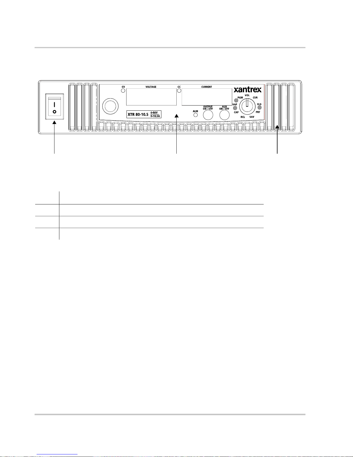
Front Panel for XTR 850 Watt and XTR 1700 Watt
1 32
Figure 1-1
Item Description
1 Front panel power switch
2 Front panel display. See Figure 1-2 for details.
3 Air Intake Vents
Front Panel: XTR 850 Watt and XTR 1700 Wa tt
1-4 975-0200-01-01
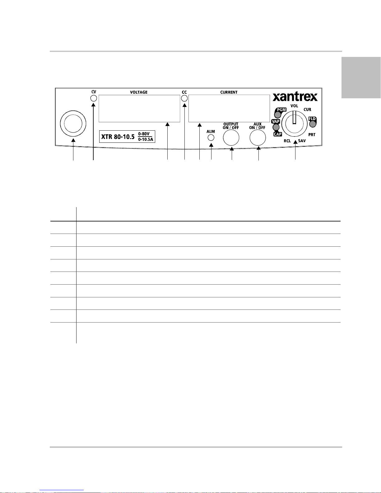
Front Panel Display and Controls
1 2 3 456 78 9
Front Panel for XTR 850 Watt and XTR 1700 Watt
1
Figure 1-2
Item Description
1 Rotary knob/Enter button
2 Constant Voltage (CV) Mode LED (green)
3 Output Voltage Display
4 Constant Current (CC) Mode LED (green)
5 Output Current Display
6 Alarm Indicator LED (red)
7 OUTPUT ON/OFF button
8 Auxiliary Output ON/OFF (AUX ON/OFF) button
9 9-Position Mode Control Knob. For detailed information, see “Configuring Settings from
Front Panel Display and Controls
the Front Panel” on page 3–2.
975-0200-01-01 1-5
Introduction
Rear Panel Connectors on XTR 850 Watt
1
6
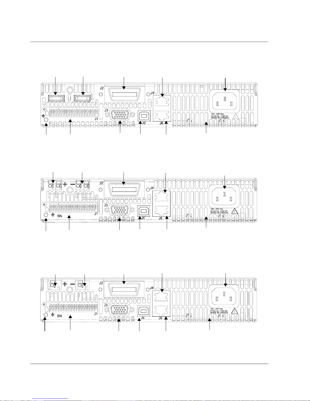
Figure 1-3
1
2
7
3
8
9
4
XTR 850 Watt Series: 6 V to 40 V Models
2
3
10
4
5
11
5
6 111087 9
Figure 1-4
6 11
Figure 1-5
XTR 850 Watt Series: 60 V to 150 V Models
1 2
3
XTR 850 Watt Series: 300 V to 600 V Models
4
10987
5
1-6 975-0200-01-01

Item Description
Rear Panel Connectors on XTR 850 Watt
1 6 V– 40 V Models: DC Output Terminal Positive
60 V–150 V Models: DC Output Connectors Positive (6.5 mm hole diameter)
300 V–600 V Models: DC Output Connectors Positive
2 6 V– 40 V Models: DC Output Terminal Negative
60 V–150 V Models: DC Output Connectors Negative (6.5 mm hole diameter)
300 V–600 V Models: DC Output Connectors Negative
3 (J2) Ethernet (ENET) or GPIB Connector (optional)
4 (J4) RS-232/RS-485 Connector In Port
5 AC Input Connector (IEC Type)
6 Chassis Ground Stud
7 (J1) Analog Programming (APG) Connector. For pin information, see page 4–5.
8 (J3) AUX Output and Isolated Analog Programming (ISOL) Connector. For pin information, see
page 4–19.
9 (J5) USB Connector
10 (J6) RS-485 Connector Multichannel Port
11 Fan Exhaust Vents
1
975-0200-01-01 1-7
Introduction
Rear Panel Connectors on XTR 1700 Watt
4
J4
J5
MADE IN CANADA
9
10
4
J4
J5
MADE IN CANADA
10
9
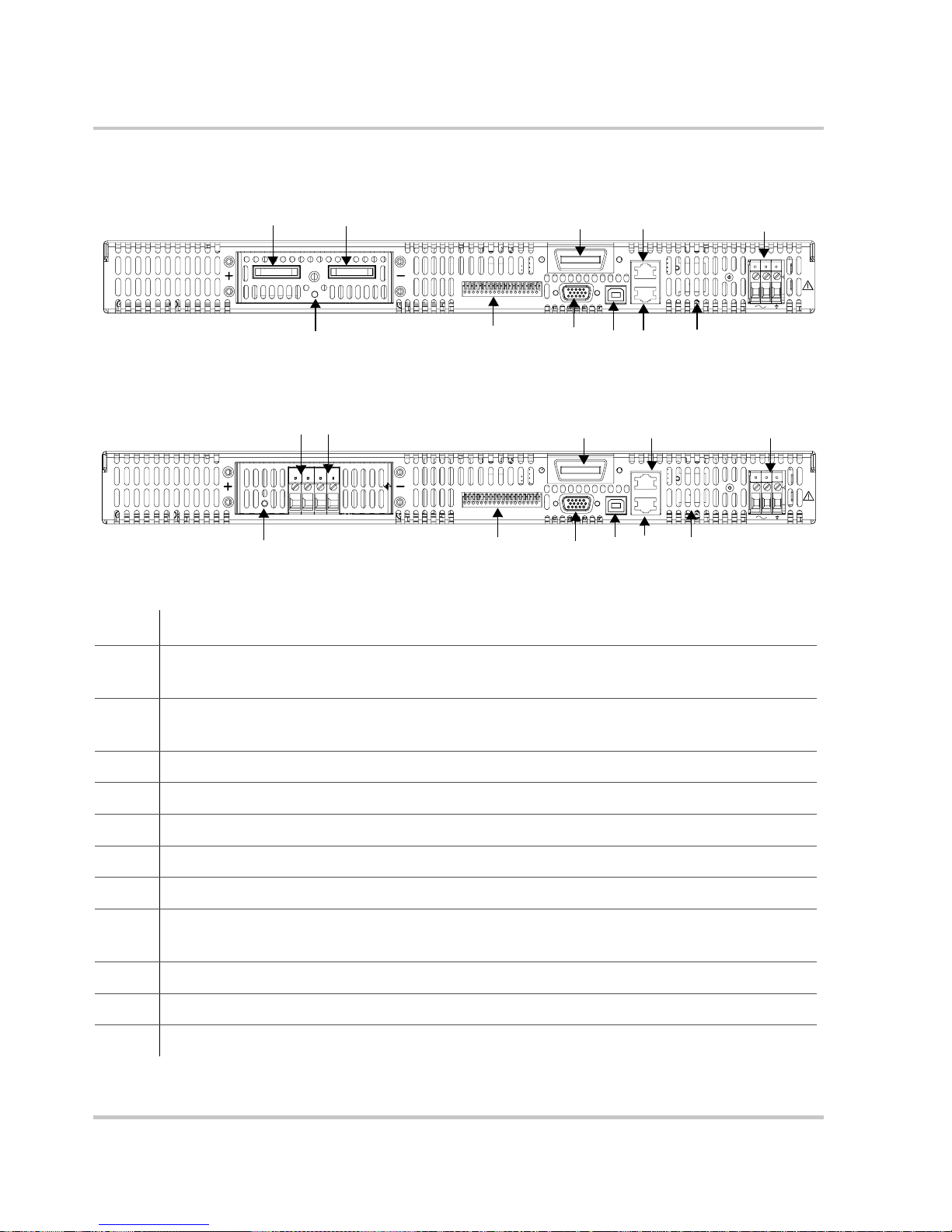
Figure 1-6
Figure 1-7
1
2
SN
6
7
XTR 1700 Watt Series: 6 V to 40 V Models
1 2
SN
6
7
XTR 1700 Watt Series: 60 V to 600 V Models
3
J2
J3
J1
8
3
J2
J3
J1
8
Item Description
1 6 V– 40 V Models: DC Output Terminal Positive (8.5 mm hole diameter)
60 V–600 V Models: DC Output Connectors Positive
5
100 - 240 Vac
47-63 Hz, 2200 VA
J6
11
5
100 - 240 Vac
47-63 Hz, 2200 VA
J6
11
2 6 V– 40 V Models DC Output Terminal Negative (8.5 mm hole diameter)
60 V–600 V Models: DC Output Connectors Negative
3 (J2) Ethernet (ENET) or GPIB Connector (optional)
4 (J4) RS-232/RS-485 Connector In Port
5 AC Input Terminal
6 Chassis Ground Stud
7 (J1) Analog Programming Connector. For pin information, see page 4–5.
8 (J3) AUX Output and Isolated Analog Programming Connector. For pin information, see
page 4–19.
9 (J5) USB Connector
10 (J6) RS-485 Connector Multichannel Port
11 Fan Exhaust Vents
1-8 975-0200-01-01

2
Installation
Chapter 2, Installation, provides information and
procedures for inspecting, installing, and testing the power
supply.

Installation
Basic Setup Procedure
Table 2-1 provides a summary of the basic setup procedure with
references to the relevant sections in this chapter. Refer to this table if you
are unfamiliar with the installation requirements for the power supply.
Complete each step in the sequence given.
Table 2-1
Step Description Action Reference
1 Inspect Inspect the power supply. “Step 1: Inspecting and Cleaning”
2 Install Install the power supply
3 Connect Input
4 Select Wires Select wires that are correctly
5 Test Perform functional tests for
6 Connect Loads Connect the load wires to the
Basic Setup Procedure
Power
on page 2–3.
“Step 2: Location and Mounting” on
(benchtop or rack mount).
Ensure adequate ventilation.
Connect AC input power. “Step 3: Connecting AC Input
rated for the maximum DC
output current.
voltage mode operation, current
mode operation, and front panel
controls.
DC output.
page 2–4.
Power” on page 2–5.
“Step 4: Selecting Load Wires” on
page 2–9.
“Step 5: Performing Functional
Tests” on page 2–11.
“Step 6: Connecting Loads” on
page 2–13.
7 Connect Remote
Sensing (if
required)
2-2 975-0200-01-01
Connect remote sensing
connectors on power supply to
load.
“Step 7: Connecting Remote
Sensing” on page 2–16.

Step 1: Inspecting and Cleaning
Initial Inspection
When you first receive your unit, perform a physical check:
1. Inspect the unit for any scratches and cracks, broken switches,
connectors or displays.
Step 1: Inspecting and Cleaning
2. For the XTR 850 Watt only, ensure that the packing box contains the
3. If you see external damage or suspect internal damage, contact
Periodic Cleaning
The power supply only requires periodic cleaning, not routine servicing.
Whenever a unit is removed from operation, clean the metal surfaces with
naptha or an equivalent solvent, and clean the front panel with a weak
solution of soap and water . Use low-pressure compressed air to blow dust
from components on the printed circuit boards.
7.5 foot (2.5
with a power cord.)
Xantrex Customer Service (see Contact Information on
an assessment. If the unit is damaged, save all packing materials and
notify Xantrex Customer Service immediately. See packing
instructions in
m) power cord. (The XTR 1700 Watt is not supplied
page iii) for
“Return Procedure” on page WA–4.
2
975-0200-01-01 2-3

Installation
Step 2: Location and Mounting
The power supply may be rack-mounted or used in benchtop applications.
Rack Mounting
The XTR 850 Watt power supply is designed to fill half of a standard
inch (483 mm) equipment rack. The XTR 1700 Watt is designed to fill
19
a standard 19
Units can be combined with the same models in the 850 W or 1700 W
series for customer applications.
Purchasing Rack Mount Kits
Contact Xantrex Customer Service (see “Contact Information” on
page iii) about purchasing the Rack Mount Kit options for XTR 850 Watt
and XTR 1700 Watt. For a list of the part numbers, see “Part Numbers for
Rack Mount Kits” on page iii. Installation information for the different
rack mount options are provided with the rack mount kits.
inch (483 mm) equipment rack.
Ventilation
For XTR product support, visit www.xantrex.com and navigate to the
XTR home page.
Whether operating the power supply in a rack or on a bench, allow air to
reach the ventilation inlets on the front and rear of the unit for cooling.
The direction of airflow is from the front of the unit to the back of the
unit. Ventilation space is not required at the top, bottom or sides of the
power supply.
2-4 975-0200-01-01

Step 3: Connecting AC Input Power
WARNING: Shock hazard
Disconnect AC power from the unit before removing the cover. Even with the
front panel power switch in the Off position, live line voltages are exposed when
the cover is removed. Repairs must be made by an Authorized Service Center.
Step 3: Connecting AC Input Power
WARNING
There is a potential shock hazard if the power supply chassis and cover are not
connected to an electrical ground via the safety ground in the AC input
connector. Ensure that the power supply is connected to a grounded AC outlet
with the recommended AC input cord configured for the available line voltage as
described in this section.
WARNING
The AC input cord is the disconnect device for the power supply. The plug must
be a non-locking plug which is readily identifiable by and accessible to the
operator. The input cord must be no longer than 9.84 feet (3 m).
XTR 850 Watt AC Input Connector
On the XTR 850 Watt, the AC input connector is a standard IEC 16 A
250 V male connector located on the rear panel of the power supply. The
AC input cord provided is rated for 30
in any country.
2
A, 300 V and appropriate for use
975-0200-01-01 2-5

Installation
XTR 1700 Watt AC Input Connector
On the XTR 1700 Watt, the AC input connector is a 3-terminal wire
clamp located on the rear panel of the power supply. See
Screw (1 place)
100 - 240 Vac
47-63 Hz, 2200 VA
Figure 2-1.
AC cover
Screw-on locknut
Figure 2-1
AC input terminal
XTR 1700 Watt A C Input Cover and Strain Relief
2-6 975-0200-01-01

XTR 1700 Watt AC Input Wire
The XTR 1700 Watt is not supplied with a power cord or a non-locking
AC plug.
must also purchase and install the correctly rated non-locking plug for
your installation.
Make sure that the wiring of the product and the AC plug comply with the
applicable local code for your installation. If you require a special cord,
contact Xantrex Customer Service (see
page iii).
Table 2-2 specifies the recommended AC input wire size. You
Step 3: Connecting AC Input Power
“Contact Information” on
2
Table 2-2
AC Input Voltage Range and
Frequency
85–265 Vac, 47–63 Hz, single
phase 3 wire
XTR 1700 Watt: Recommended AC Input Wire
XTR 1700 Watt AC Input Wire Connection
To make the AC input wire connections:
1. Strip the outside insulation on the AC cable approximately 4 in.
mm). Trim the wires so that the ground wire is 0.5 in. (12 mm)
(100
longer than the other wires. Strip 0.55
of the wires.
2. Loosen the screw on the AC cover and remove the AC cover.
3. Unscrew the base of the strain relief from the helix-shaped body.
Insert the base through the outside opening in the AC input cover and,
from the inside, screw the locknut securely onto the base.
Wire Specifications
3 × 10 AWG (2 wi re plu s safety gro und),
stranded copper, 60 °C minimum, 300
The input cord must be no longer than
9.84 feet (3 m).
in.(14 mm) at the end of each
V.
4. Slide the helix-shaped body onto the AC cable. Insert the stripped
wires through the strain relief base until the outer cable jacket is flush
with the edge of the base. Tighten the body to the base while holding
the cable in place. The cable is now securely fastened inside the strain
relief.
5. Route the AC wires to the input connector terminals as required. For
AC input terminal locations, see lower inset in
the wiring, loosen the terminal screw, insert the stripped wire into the
terminal, and tighten the screw securely.
975-0200-01-01 2-7
Figure 2-1. T o connect

Installation
6. Route the wires inside the cover to prevent pinching. Fasten the AC
cover to the unit using the screw provided. See
Figure 2-1.
2-8 975-0200-01-01

Step 4: Selecting Load Wires
This section provides recommendations for selecting minimum load wire
sizes.
Load Wiring
To select the wiring for connecting the load to the power supply, consider
the following factors:
• Insulation rating of the wire.
• Current carrying capacity of the wire.
• Maximum load wiring length for operation with remote sense lines.
• Electrical noise and impedance effects of the load lines.
Insulation Rating
Use load wiring with a minimum insulation rating equivalent to the
maximum output voltage of the power supply.
Current Carrying Capacity
Step 4: Selecting Load Wires
2
The load wiring must have a current carrying capacity greater than the
output rating of the power supply to ensure that the load wiring will not be
damaged if the load is shorted.
rating for various gauges of wire rated for 105 °C operation, based on a
maximum current density of 450
Operating at the maximum current rating shown in Table 2-3 results in an
approximately 30 °C temperature rise for an appropriately-sized load wire
operating in free air. Where load wiring must operate in areas with
elevated ambient temperatures or bundles with other wiring, use larger
gauges or wiring rated for higher temperatures.
Table 2-3
Wire Size
(AWG)
20 2.5 6 61
18 4 4 97
16 6 2 155
14 10 1 192
12 16 1/0 247
10 21 2/0 303
8 36
Current Carrying Capacity for Load Wiring
Maximum Current
(Amps)
Table 2-3 shows the maximum current
A/cm2.
Wire Size
(AWG)
Maximum Current
(Amps)
975-0200-01-01 2-9

Installation
Maximum Load Wiring Length For Operation With Sense Lines
Figure 2-2
Noise and Impedance Effects
T o minimize noise pickup or radiation, use shielded twisted pair wiring of
the shortest possible length for load sense wires. Connect the shield to the
power supply chassis. Where shielding is impossible or impractical,
simply twisting the wires together will offer some noise immunity.
Maximum Load Wire Length for 1 V Line Drop
2-10 975-0200-01-01

Step 5: Performing Functional Tests
The functional test procedures include:
• Power-on and front panel functional checks
• Voltage mode operation and current mode operation checks.
For information on local operation, see “Local Operation” on page 3–1
for adjusting front panel controls and settings.
Step 5: Performing Functional Tests
Powering the Power Supply On/Off
To power on the power supply:
1. Ensure that the front panel power switch is in the Off position.
2. Ensure that the AC line voltage is within operating range.
3. Connect the line cord to a grounded AC outlet.
4. Turn the front panel power switch to the On position.
After a short power-on delay, 8888 8888 illuminates on the output
voltage and current displays, followed by PSU On.
After approximately 1 second, the display returns to normal status.
To power off the power supply:
u Turn the front panel power switch to the Off position.
AC FAIL will blink on the display. The ALARM LED illuminates.
After a short delay, all lights on the display will not be illuminated.
2
975-0200-01-01 2-11

Installation
Voltage and Current Mode Operation Checks
To perform the voltage and current mode operation checks:
1. Ensure that the front panel power switch is in the On position and the
output is disconnected.
2. If the OUTPUT ON/OFF button is illuminated, press the button to
turn off the output.
3. To check voltage mode operation, turn the mode control knob to the
VOL position.
The voltage set point will blink dimming and then return to full
brightness. For more information, see
4. Adjust the voltage to 5 V.
5. T o check current mode operation, turn the mode con trol knob to CUR
position.
Verify that the current set point is blinking in the output current
display.
“Local Operation” on page 3–1.
6. Adjust the current to 1 A.
7. Press the OUTPUT ON/OFF button to turn On.
8. Turn the front panel power switch to the Off position.
9. Turn the front panel power switch to the On position.
10. Connect a short circuit across the output terminals. Use leads of
sufficient current carrying capacity. (See
“Step 4: Selecting Load
Wires”.)
11. If the OUTPUT ON/OFF button is not illuminated, press the button to
turn on the output.
CC Mode LED illuminates and the voltage and current are displayed.
CV Mode LED illuminates and the preset load current is displayed.
12. Turn the front panel power switch to the Off position.
2-12 975-0200-01-01
Step 6: Connecting Loads
This section describes how to connect loads to the power supply for both
single and multiple loads.
WARNING: Shock hazard
There is a shock hazard at the power supply output when operating at an output
greater than 40 V. T o protect personnel against accidental contact with hazardous
voltages, ensure that the load and its connections have no accessible live parts.
CAUTION
When making connections to the output terminals, ensure termin als of opp osite
polarity do not touch. Load cables and sense wires should be provided with strain
relief.
DC Output Connectors
Step 6: Connecting Loads
2
6 V–40 V Models
60 V–600 V Models
WARNING: Shock hazard
Disconnect the AC input before making any connections. A shock hazard may be
present at the output terminals. Allow 15 seconds after the AC power has been
removed before making any connections.
The 6 V–40 V models of the XTR 850 Watt and XTR 1700 Watt are
equipped with output terminals, as shown in
The 60 V–600 V models of the XTR 850 Watt and XTR 1700 Watt are
equipped with output connectors, as shown in
Figure 1-7.
Figure 1-3 and Figure 1-6.
Figure 1-4, Figure 1-5, and
975-0200-01-01 2-13

Installation
Inductive Loads
To prevent damage to the power supply from inductive kickback, connect
a diode across the output. The diode must have a voltage rating at least
20% greater than the power supply's output voltage and have a current
rating greater than or equal to the power supply's output rating. Connect
the cathode to the positive output and the anode to the return.
Where positive load transients such as back EMF from a motor may
occur, connect a Transient Voltage Suppressor (TVS) or a varistor across
the output to protect the power supply. The breakdown voltage rating for
the TVS or varistor must be approximately 10% higher than the rated
supply output.
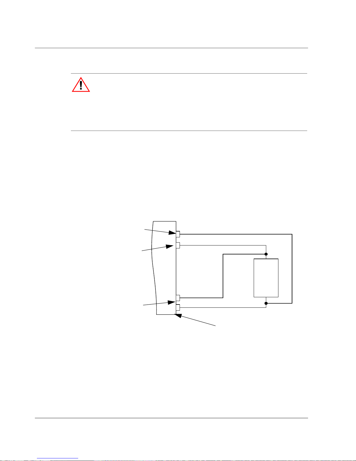
Connecting Single Loads
Figure 2-3 shows the recommended load connections for a single load
which is sensing its voltage locally. Local sense lines shown are the
default connections at the rear panel APG J1 connector (see
page 4–5). The load lines should use the largest gauge and shortest length
of wire possible to ensure optimal performance.
Figure 4-1 on
You do not need remote sensing for basic operation of your power supply.
However, if you wish to correct any small drops in your load lines, then
use the remote sensing feature. See
“Step 7: Connecting Remote Sensing”
on page 2–16 for more information.
Output
–
Output
J1.1
J1.2
J1.5
J1.6
Terminal
+
–
Terminal
Load
Power Supply
Figure 2-3
Local Sense
–
+
Local Sense
+
Connecting Single Loads
2-14 975-0200-01-01

Connecting Multiple Loads
The proper connection of distributed loads is an important aspect of
power supply use. The common method of connection is a radial load
connection. Power is connected to each load individually from a single
pair of terminals designated as the positive and negative distribution
terminals. This pair of terminals may be the power supply output
terminals, the load terminals, or a distinct set of terminals especially
established for distribution use. In this scheme, there are no ground loops
and the effect of one load upon another is minimized.
Step 6: Connecting Loads
2
975-0200-01-01 2-15
Installation
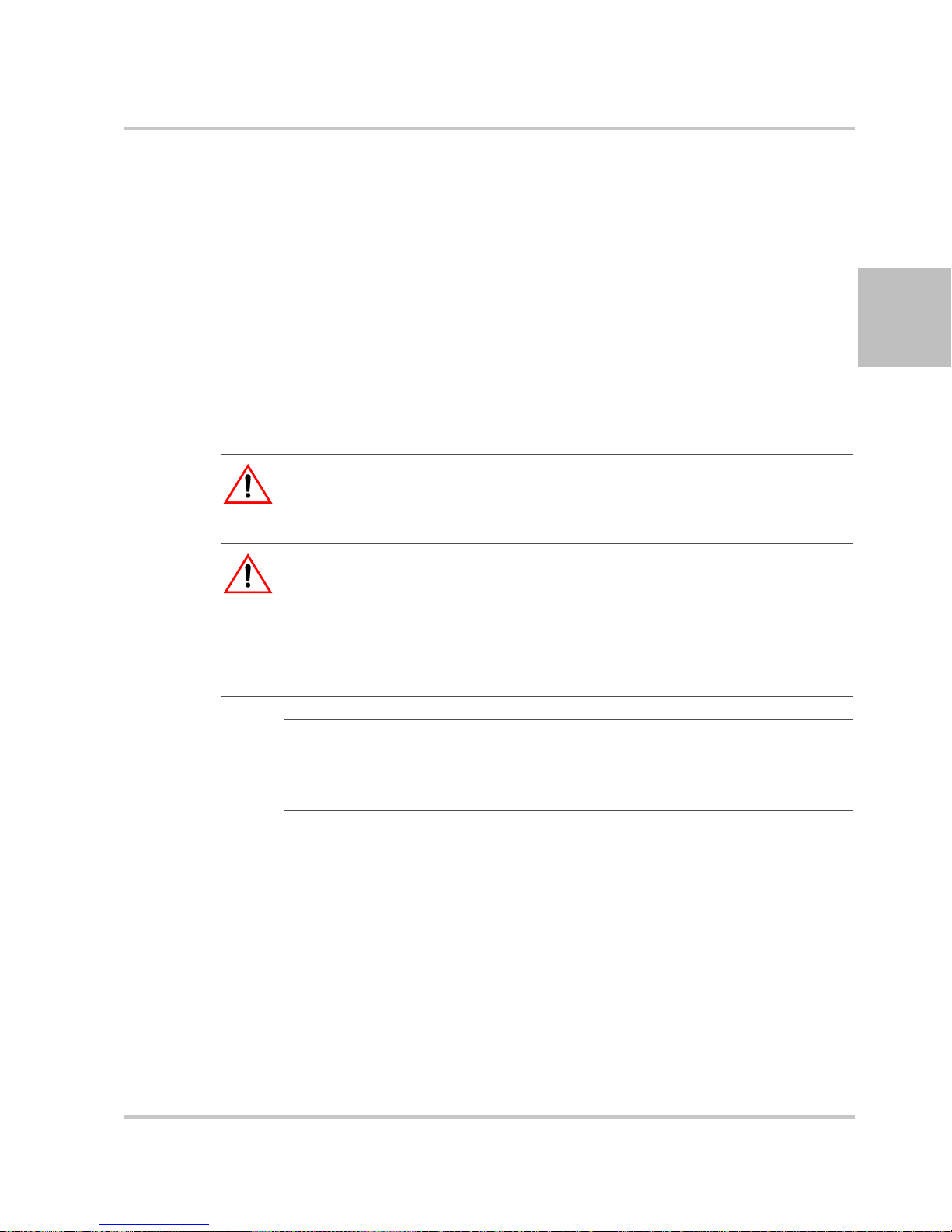
Step 7: Connecting Remote Sensing
WARNING: Shock hazard
There is a potential shock hazard at the sense connectors when using a power
supply at an output greater than 40 V. Select wiring with a minimum insulation
rating equivalent to the maximum output voltage of the power supply for use as
local sense jumpers or for remote sense wires. Ensure that connections at the load
end are shielded to prevent contact with hazardous voltages.
Remote sensing permits you to shift the regulation point of the power
supply from the output terminals to the load or other distribution
terminals.
Use shielded twisted pair wiring of 20 to 26 AWG for best noise
performance. Make sure that the shielded twisted pair wiring insulation is
rated higher than the maximum output voltage of the power supply. If
possible, one end of the shield of the sense lines should be attached to the
chassis ground of the power supply.
Pin J1.6 on APG
connector
Pin J1.1 on APG
connector
Output terminals on
power supply
Figure 2-4
Remote Sense Connection
-SNS
+SNS
LOAD
output +
output -
Chassis ground stud
To connect the remote sense wires:
1. Ensure that the front panel power switch is in the Off position.
2. Using a small flat blade screwdriver, remove the two sense jumpers
from pins J1.1 and J1.2, and from pins J1.5 and J1.6 on the APG
Connector. See
Figure 4-1, “APG Connector Terminals” on page 4–5.
2-16 975-0200-01-01
Step 7: Connecting Remote Sensing
3. Connect one end of the shielded twisted pair wire to the chassis
ground point on the power supply.
4. Connect the positive sense line (+SNS) from the positive regulation
point as close as possible to the load terminals to pin J1.1.
5. Connect the negative sense line (–SNS) from the return of the load to
pin J1.1.
To compensate for losses in power leads connected to the output, the
power supply provides sense connections beside the output terminals.
With remote sense leads in place, the power supply regulates to the
displayed voltage at the point where the sense lines are connected to
the output leads. With the sense lin es d isconn ected, th e power supply
regulates the voltage at the output terminals.
CAUTION
Do not operate the power supply with sense lines connected to the load without
also connecting the load power leads to the output terminals.
2
CAUTION
Avoid reversing positive (+) and negative (–) sense connections.
When using remote sense to compensate for load line losses, ensure that the
positive sense line is connected to the positive load terminal and the negative
sense line is connected to the negative load terminal. Do not reverse these
connections or the power supply may be damaged.
Important:
sensing can cause voltage instability due to inductance of the load leads.
Measures to reduce inductance and/or capacitance (raising resonant frequency)
or using local sense can be beneficial in stabilizing the system.
Long load leads with large capacitance at the load and remote
975-0200-01-01 2-17

2-18

3
Local Operation
Chapter 3, Local Operation, provides the procedures for
local (front panel) operation such as:
• Configuring settings.
• Operating in constant voltage mode and constant
current mode.
• Using the protection features.
• Using multiple power supplies.

Local Operation
Introduction
Once you have installed the power supply and connected both the AC
input power and the load (covered in
power supply is ready for local operation. To turn the power supply on,
see
“Powering the Power Supply On/Off” on page 2–11.
“Installation” on page 2–1), the
Configuring Settings from the Front Panel
Using the 9-Position Mode Control Knob
The 9-position mode control knob is used with the Rotary knob/Enter
button to configure settings in local operation. See
Panel Display and Controls” on page 1–5 for location of the front panel
features.
The mode control knob is used to select one of nine modes: VOL, CUR,
FLD, PRT, SAV, RCL, CAP, and VAP. See
detailed information on the nine modes.
Figure 3-1 and Table 3-1 for
Figure 1-2, “Front
Figure 3-1
9 Position Mode Control Knob
Using the Rotary knob/Enter button
The Rotary knob/Enter button is used to change settings and set the value
selected. The front panel displays information on the output voltage and
output current displays. Each display has a maximum of four characters
that are made up of 7 segments.
Coarse and Fine Adjustment Modes
Coarse
adjustment
mode
3-2 975-0200-01-01
When using local operation to set the current and voltage set points, enter
the coarse adjustment mode followed by the fine adjustment mode. The
coarse adjustment mode quickly adjusts the settings in large increments to
reach the desired value.

Configuring Settings from the Front Panel
Fine adjustment
mode
Pressing the Rotary knob/Enter button to change the mode to fine
adjustment mode provides the ability to manipulate the last significant
digit. Once the exact desired value for the setting has been selected, press
the Rotary knob/Enter button to commit the value to the unit. The coarse
and fine adjustment modes are used for setting the voltage and current set
points, OVP and UVP settings.
Table 3-1
9 Positions on the Mode
Control Knob
VOL (Voltage Programming) Select the voltage set point in coarse
CUR (Current Programming) Select the current set point in coarse
FLD (Foldback) Select Foldback option: CC, CV or
Select and Set from the Front Panel
Turning the Rotary Knob lets you…
or fine adjustment modes. See
“Automatic Mode Crossover” on
page 3–11.
or fine adjustment modes. See
“Constant Current Mode Operation”
on page 3–11.
none. See
on page 3–22.
“Setting Foldback Mode”
Pressing the Enter Button lets
you…
Set the value selected and
cycle to the next setting.
3
Set the value selected and
cycle to the next setting.
Set the value selected and
cycle to the next setting.
PRT (Protection) Select the OVP set point (see
page 3–24).
Select the UVP set point (see
page 3–25.)
Select OTP temperature and
Shutdown (see
SAV (Save User Preset) Select the user setting memory
location. See
Memory Locations” on page 3–28.
RCL (Recall User Preset) Select the user setting memory
location. See
Setting Memory Locations” on
page 3–29.
CAP (Current Analog
Programming)
VAP (Voltage Analog
Programming)
Select the programming source and
select the range.
Select the programming source and
select the range.
page 3–26.)
“Saving User Setting
“Recalling User
Set the value selected and
cycle to the next setting.
Save user setting memory
values.
Load user setting memory
values into the power supply.
Set the value selected and
cycle to the next setting.
Set the value selected and
cycle to the next setting.
975-0200-01-01 3-3

Local Operation
Navigating the Menu System
The menu system of the XTR follows a select and set model with the
exception of the VOL and CUR modes. See
Modes”.
The general procedure for setting up the features in the select and set
model is:
1. To select a mode, rotate the 9-position mode control knob to the
desired mode or press the Rotary knob/Enter button once to activate
the current selection on the mode control knob. See
2. T o sel ect the feature or setting, rotate the Rotary knob/Enter butt on to
scroll through the different available settings of that mode.
The settings appear on the output current display.
3. Press the rotary knob/Enter button to select the feature or setting.
4. Set each value using the Rotary knob/Enter button. When the value
has been selected, press the Rotary knob/Enter button to commit the
updated value. Additional values may become available, depending
on the setting that is being configured.
“Setting VOL and CUR
Figure 3-2.
Setting VOL and CUR Modes
The only exceptions to the select and set model are the VOL and CUR
modes which do not allow the selection of tracking and select and set
mode by rotating the Rotary knob/Enter button. In VOL and CUR modes,
the default entry mode setting is automatically selected as either voltage
or current tracking, respectively.
Voltage and current values can be set in tracking mode or select and set
mode using the Rotary knob/Enter button:
• Tracking mode—the new values take effect as the Rotary knob/Enter
button is rotated.
• Select and set mode—the new values do not take effect until the
Rotary knob/Enter button is pressed. See
Inactivity Timeout” on page 3–6.
To access the tracking mode for entering voltage and current:
1. Select the VOL or CUR position on the mode control knob.
If the set point is blinking, the unit is in coarse tracking mode.
• When the VOL mode is selected, the voltage set point will blink in
the output voltage display.
“Normal Display Mode and
3-4 975-0200-01-01

Navigating the Menu System
• When the CUR mode is selected, the current set point will blink in the
output current display.
2. Use the Rotary knob/Enter button to adjust the set point.
The adjustments you make to the set point affect the opposing output
value (voltage when in CUR mode or current when in VOL), which
will update in the non-blinking display.
3. Press the Rotary knob/Enter button to enter fine adjust tracking mode.
The set point blinks faster when the unit is in fine adjust tracking
mode.
4. Use the Rotary knob/Enter Button to fine tune the set point.
5. Once the set point has been selected, press the Rotary knob/Enter
Button to exit tracking mode and return to normal display mode.
To access the select and set entry mode for the voltage and current set
points:
1. Select VOL or CUR position on the mode control knob.
2. Press the Rotary knob/Enter button twice to scroll past the coarse and
fine tracking modes without making any adjustment to the value.
Coarse select and set mode has been selected.
3. If a change is made accidentally in tracking mode, select and set
mode will not be available and you’ll need to start again at Step 1.
4. Select the desired value for this set point and then set the value using
the Rotary knob/Enter button.
3
975-0200-01-01 3-5

Local Operation
Normal Display Mode and Inactivity Timeout
Normal display mode appears on the output voltage and current displays
when the configuration changes from the front panel have been completed
or when the inactivity timeout occurs (default is 3 seconds). Normal
display mode shows the output voltage and current values.
If a timeout occurs before the changes made to the value have been set,
the changes will not be saved and you will have re-enter the changes. The
inactivity timeout is variable from 1 to 20 seconds and can only be
changed using the SCPI command.
The SCPI command (s) for these instructions are:
[:]SYSTem[<channel>]:FPANel[:TIMeout]
Important:
beginning users and expert users don't have to use the same timeout
Each user memory setting location stores the timeout so that
3-6 975-0200-01-01

Navigating the Menu System
VOL
CUR
FLD
PRT
SAV
RCL
CAP
VAP
CV
CC
None
OVP
UVP
Overheat Protecti on
Shutdow n Logic
Select Pres et
Select Pres et
Off
Voltage Isolated
Voltage Non-Isolated
Res is tive Is olated
Res is tive N on-Is olated
Off
Voltage Isolated
Voltage Non-Isolated
Res is tive Is olated
Res is tive N on-Is olated
Coarse Volt Pre-Se tCoar se Volt Track ing
Coarse Current Pre-SetCoarse Current Tracking Fine Cu rrent Pre- SetFine Cur rent Tr ack ing
Fold Delay
Fold Delay
OVP Coarse Adjust OVP Fine Adjus t
UVP Coarse Adjust UVP F ine Adjust
On/Off
1/0
Legend:
Cur r ent APG Level
Cur r ent APG Level
Cur r ent APG Level
Cur r ent APG Level
Voltage APG Level
Voltage APG Level
Voltage APG Level
Voltage APG Level
Fine Volt Pre-SetFine Volt Tracking
Press R otar y Knob/Enter But ton
when no modification of t he
trac king value has been made.
Press R otar y Knob/Enter But ton
Rotate Rotary Knob/Enter
Button
Mode Knob State
Setting/Value
3
PGM
Figure 3-2
Front Panel Menu System
USB
LAN
GPIB
RS-232
RS-485
Slave Address (1-30)
Local Lock
975-0200-01-01 3-7
Address (1-30)
Address (1-30)
Address (1-30)
Data Rate
Data Rate
On/Off
Address (1-30)
Address (1-30)

Local Operation
Display Messages on the Front Panel
The front panel displays on the power supply will use text as shown in
Table 3-2 to indicate the status or mode.
Table 3-2
Display Text Text Description
0 Negative Polarity
232 RS 232
485 RS 485
8888 All segments On, Power Up
| Positive Polarity
AC Alternating Current
ADDr RS 485 Address
ANPR Analog Programming
AS Power On Autostart
AvAS Auxiliary Autostart
BP5 Data rate (BPS)
CAPr Current Analog Programming
CLr Clear
CC Constant Current
CU Constant Voltage
CrPC Coarse Current Pre-set Mode
CrPU Coarse Voltage Pre-set Mode
CUrr Current
deLa Fold Delay
done Done
Err Error (debug)
F0LD Foldback
FAIL Fail
FAn Fan
FLA Flash
FnpC Fine Current Preset Mode
FnPU Fine Voltage Preset Mode
FLd Foldback
GPIB GPIB Interface
In Interlock
LAn ENET Interface
LE C Current APG Level
Front Panel Display Text
3-8 975-0200-01-01

Display Messages on the Front Panel
Table 3-2
Display Text Text Description
LE U Voltage APG Level
Loc Lock
LOCL Local
OFF Off
OCP Over Current Protection
O7P Over Temperature Protection
OUP Over Voltage Protection
OvPF Over Voltage Protection fine adjustment
On On
OUPC OVP Calibration
POL Polarity
Pr0 Protection mode
PSU Power Supply Unit
R IS Isolated Resistive Analog Programming
rCL Recall Preset
rE Remote Programming/Interface
rnIS Non-Isolated Resistive Analog Programming
SAFE Safe
SAUE Save Preset
Sd Shutdown
SLA Slave Remote Interface
U IS Isolated Analog Voltage Programming
UN IS Non-Isolated Analog Voltage Programming
USb USB Interface
UUP Under Voltage protection coarse adjustment
UvPF Under Voltage protection fine adjustment
UAPr Voltage Analog Programming
UOL Voltage
Front Panel Display Text
3
A blinking numeric value is eith er a vol tage or current set point in tracking
mode. The display in which the set point appears, output voltage or output
current display, indicates the type of set point, voltage or current.
975-0200-01-01 3-9

Local Operation
Standard Operation
The power supply can be controlled by two methods, either from the front
panel or from any of the remote interfaces. Front panel control is referred
to as local operation (default setting) while control via any of the remote
interfaces is called remote operation. To set up the power supply for
remote operation, see
connection has been established, the power supply can switch seamlessly
between local operation and any digital interface (RS-232, RS-485,
GPIB, USB and Ethernet).
Local lockout is a feature that allows the front panel to be locked so that
accidental button presses are ignored. This feature is often used to lock
out the front panel while a user is controlling the power supply from a
remote location.
The output of the power supply has two modes of operation: Constant
Voltage (CV) mode (see
(see page 3–11). Both of the operating modes are available regardless of
which control method (local or remote) is used.
Chapter 5, “Remote Operation”. Once the remote
page 3–11) and Constant Current (CC) mode
Operating Modes
The output mode in which the power supply operates at any given time
depends on the following factors:
• Output voltage set point V
• Output current set point I
• Impedance of the attached load R
The two output modes of operation are Constant Voltage (CV) mode (see
page 3–11) and Constant Current (CC) mode (see page 3–11).
Output enabled When the output is turned on, both the voltage and current rise as quickly
as possible to try and reach the set points (V
configured prior to enabling the output. Initially the unit will operate in
CV mode, which is the default mode. As the voltage and current rise to
meet the requirements of the load, the set point that is reached first (based
on the R
either V
L,
SET
and I
supply will remain in. The operating mode is indicated by either the CC
mode LED or the CV mode LED, one of which will illuminate on the
front panel.
SET
SET
L
and I
SET
) will determine which mode the power
SET
SET)
that were
3-10 975-0200-01-01

Standard Operation
Output disabled The mode of operation is not determined until the output is enabled. The
CV and CC mode LEDs will not indicate the mode while the output is
disabled.
Constant Voltage Mode Operation
If the output is enabled and the configured current set point is much
higher than the requirements for the attached load, then the voltage will
rise until it reaches the voltage set point. When the output voltage reaches
the voltage set point, it stops rising. The unit will continue to operate in
CV mode. The load current will still vary to meet any changes in required
load current draw resulting from a change in the attached load.
Constant Current Mode Operation
If the output is enabled, the voltage and current start to rise. At this time
the unit is operating in CV mode (default operational mode). As the load
current drawn reaches the value of the output current setting, the unit will
switch to CC mode and not allow any additional current to be drawn
above the value of I
voltage will still vary to meet any changes in required output voltage
resulting from a change in the attached load.
Automatic Mode Crossover
Mode crossover occurs when the unit makes the switch between operating
modes. Crossover can occur from CV to CC or vice versa, depending on
how the attached load resistance changes.
relationships between the variables.
For example, if the unit was initially operating in CV mode with the
output voltage at the voltage set point and the load current below the I
and the attached load resistance began to decrease, the current would rise
to meet this change in the load. The load current will increase in
proportion to the decrease in the load resistance until the load current
drawn reaches the current set point. At this point further decreases in load
resistance (increased load current requirements) will cause the unit to
cross over into CC mode where the output voltage will vary with
changing load resistance and the load current will remain at the I
value.
. The unit is now operating in CC mode. The
SET
Figure 3-3 shows the
SET
SET
3
975-0200-01-01 3-11
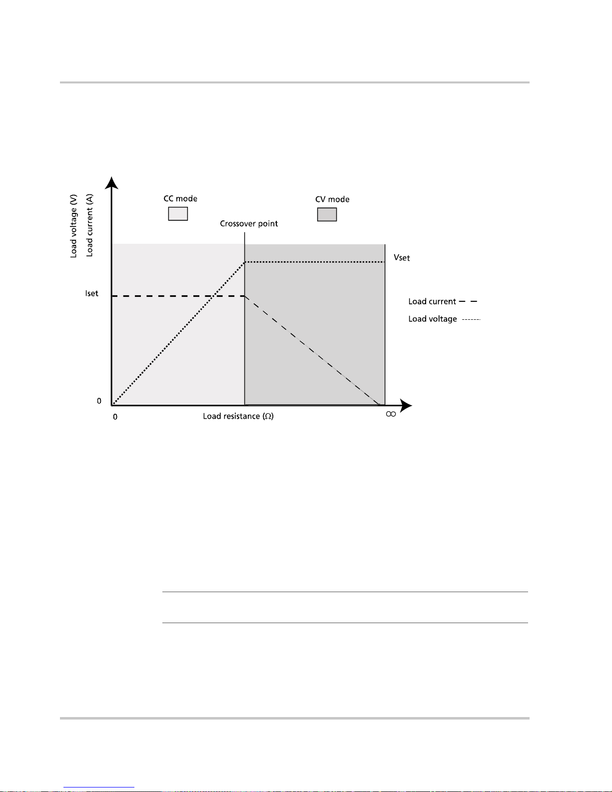
Local Operation
The reverse operating mode change can also occur if the load resistance is
increased to the point that the required load current drops below the I
SET
value. At that point the power supply would crossover to CV mode and
the load current would be free to vary as the load resistance changed
Figure 3-3
Operating Modes
To set the voltage set point (V
1. Turn the mode control knob to the VOL position or press the Rotary
knob/Enter button if the mode control knob is already at the VOL
position.
The voltage set point is blinking in the output voltage display. The
output current will be displayed in the output current display.
2. Set the desired voltage value using the Rotary knob/Enter button.
Important:
change the set points for OVP.
3. Press the Rotary knob/Enter button to transition to Fine Adjust mode.
The set point will blink faster to indicate fine adjust tracking mode.
4. Set the desired voltage value using the Rotary knob/Enter button.
SET):
If you can’t get the set point to the desired level, you may need to
3-12 975-0200-01-01

Standard Operation
5. Once the desired value has been set, press the Rotary knob/Enter
button to commit the setting.
Quick Tip
Remote operation
uses these SCPI
commands. See
page 5–1.
Important:
output voltage up to 105% over the model-rated maximum value. The power
supply will operate within these extended ranges, but full performance to
specification is not guaranteed.
The control circuits have been designed to allow you to set the
The SCPI command (s) for these instructions are:
[[:]SOURce[<channel>]]:VOLTage[:LEVEl][:IMMediate]
[:AMPLitude]
Important:
are limited by the Over Voltage Protection and Under Voltage Protection settings.
To set the current set point (I
The maximum and minimum setting values of the output voltage
):
SET
1. Turn the mode control knob to the CUR position or press the Rotary
knob/Enter button if the mode control knob is already at the CUR
position.
The voltage set point is blinking in the output voltage display. The
output current will be displayed in the output current display.
3
2. Set the desired current value using the Rotary knob/Enter button.
3. Press the Rotary knob/Enter button to transition to Fine Adjust mode.
The set point blinks faster to indicate fine adjust tracking mode.
4. Set the desired current value using the Rotary knob/Enter button.
5. Once the desired value has been set, press the Rotary knob/Enter
button to commit the setting.
Important:
current can be set up to 105% over the model-rated maximum values. The power
supply will operate within these extended ranges, but full performance to
specification is not guaranteed.
The control circuits have been designed so that output
The SCPI command (s) for these instructions are:
[[:]SOURce[<channel>]]:CURRent[:LEVEl][:IMMediate]
[:AMPLitude]
975-0200-01-01 3-13

Local Operation
Shipped Configuration (Local Operation)
The power supply is configured for local operation at the factory. See
Table 3-3 for a summary of this configuration. For more information on
default settings, see Table 3-9 on page 3–35.
Table 3-3
Local Control Confi guration Additional References
Use the front panel controls to
adjust the output voltage and
current set point settings.
The OVP set point is adjusted at
the front panel to 105% above the
maximum rated output voltage.
Shipped Configuration
Turning the Output On/Off
Turning the output on will also turn off the ALARM LED if the ALARM
LED has been latched on due to an alarm triggering and automatically
clearing. See
To turn on the output power:
u Press the OUTPUT ON/OFF button on the front panel or enter the
SCPI command.
“Alarms and Errors” on page 3–17.
See Chapter 3, “Local Operation” for front
panel operation. See Chapter 4, “Analog
Programming (APG) and Isolated Analog
Programming (ISOL)” for analog
programming procedures.
See “Using Over Voltage Protection
(OVP)” on page 3–24 for the adjustment
procedure.
The OUTPUT ON/OFF button will illuminate.
To turn off the output power:
u Press the OUTPUT ON/OFF button when the OUTPUT ON/OFF
button is illuminated.
The output will turn off and the LEDs will not be illuminated.
Important:
activated. See
Quick Tip Remote
Operation uses
these commands.
page 5–1.
See
3-14 975-0200-01-01
The SCPI command (s) for these instructions are:
[:]OUTPut[<channel>][:POWer][:STATe]
The main output will not turn on if the shutdown function is
“Using the External Shutdown Function” on page 3–31.

Turning the Auxiliary Output On/Off
To turn on the auxiliary output:
u Press the AUX ON/OFF button on the front panel.
The AUX ON/OFF button will illuminate.
Turning the Auxiliary Output On/Off
Important:
and Pin J3.2 (or Pin J3. 6 COM_ISOLATED) are shorted.
See “AUX Output and Isolated Analog Programming (ISOL) Connector” on
page 4–19.
To turn off auxiliary output:
u Press the AUX ON/OFF button on the front panel again.
The AUX ON/OFF button will not be illuminated.
If the auxiliary output is activated, +5 V on J3.9 (+AUX1) and +15 V on
J3.11 (AUX2) will be present with respect to Pin J3.2 or Pin J3.6
(COM_ISOLATED). (See also
Programming (ISOL) Connector” on page 4–19 for more details.)
The SCPI command (s) for these instructions are:
[:]OUTPut[<channel>]:AUXiliary[:STATe]
The auxiliary output will not turn on if Pin J3.1 (AUX_ON_OFF)
“AUX Output and Isolated Analog
Output Auto Start Mode (Auto Restart)
The Auto Start mode establishes the state of the output of the power
supply after recovery from a complete power cycle (all front panel LEDs
are not illuminated).
3
If Auto Start mode is set to On, the power supply output will return to its
previous value when the power supply is powered up again.
If Auto Start mode is set to Off, the power supply output will remain of f
after the power supply is powered up again.
To change the Auto Start mode:
1. Press and hold the OUTPUT ON/OFF button for 1 second.
AS On or AS Off is displayed.
2. Switch the Auto Start mode.
The SCPI command (s) for these instructions are:
[:]OUTPut[<channel>][:POWer][:STATe]:PowerON[:STATe]
975-0200-01-01 3-15

Local Operation
Auxiliary Auto Start Mode
The Auxiliary Auto Start mode determines the state of the auxiliary
output after a complete power cycle (all front panel LEDS are not
illuminated). With Auxiliary Auto Start mode turned to On, the auxiliary
output will be activated after the power supply is powered up again.
To define the Auxiliary Auto Start mode:
1. Press and hold the AUX ON/OFF button for 1 second.
AuAS On or AuAS Off is displayed.
2. To change to status to On or Off, press the AUX ON/OFF button.
The SCPI command (s) for these instructions are:
[:]OUTPut[<channel>]:AUXiliary:PowerON[:STATe]
3-16 975-0200-01-01

Alarms and Errors
Several conditions can cause alarms in the XTR. Some conditions are:
• From user configurable features.
• Controlled in hardware and will trigger regardless of configuration.
All alarms, with the exception of the Fan alarm, will result in the output of
the power supply being disabled. The Fan alarm does not affect the output.
When an alarm is triggered, the appropriate alarm message will begin
blinking on the display and the Alarm LED will be illuminated.It is
possible that more than one alarm will trigger at the same time. When this
occurs, the alarm with the highest precedence will blink on the display.
Table 3-4 lis t s the precedence of alarms. If the alarm is cleared and the
event which caused the alarm has not been corrected, then the alarm may
trigger again immediately . Fix the reason for the alarm before you clear it.
Alarms and Errors
3
Table 3-4
Alarm Precedence Output
AC Fail 1 (Highest) Yes No
Over Temperature Protection (OTP 2 Yes Yes
Over Temperature Protection (OTP) Slave
(1700 W version only)
Fan 4 No Yes
Fan Slave (1700 W version only) 5 No Yes
Interlock 6 No No
Over Voltage Protection 7 No No
Over Current Protection 8 No No
Foldback 9 Yes Yes
External Shutdown 10 (Lowest) No Yes
Alarm Order of Precedence
Latch
3 Yes Yes
Maskable Display
AC Fail
O7P Pro
O7P Pro
FAn Pro
FAn Pro
In Loc
OVP Pro
OCP pro
FLD Pro
SD POL
Flash Checksum Failure
1.The Flash Checksum Failure alarms are an exception as they are a terminal alarm that can only
occur during boot up. It can only be cleared by doing a soft reset (losing the configuration of the
unit) or by power cycling the unit.
975-0200-01-01 3-17
1
N/A N/A N/A
FLA FAIL

Local Operation
Clearing Alarms
Clearing Triggered and Manual Alarms
To clear a triggered alarm, use one of the following methods:
• Turn the power supply Off and then On.
• Press and hold the Rotary knob/Enter button for 3 seconds.
• Press the reset key combination (Flash Fail ONLY). See “Resetting the
Power Supply” on page 3–35.
To clear a manual alarm:
1. Press the Rotary knob/Enter button for 3 seconds.
The Alr Clr message will be displayed on the front panel for a few
seconds.
Important:
highest precedence alarm is cleared. If another alarm has occurred, then this
alarm will not become the highest precedence alarm and will begin blinking on
the display.
2. Repeat the alarm clearing until you have cleared all alarms.
Clearing a Flash Failure Alarm
The Flash Failure alarm is the only exception for clearing alarms. Flash
failure can only be cleared by a reset (see
on page 3–35) or by power cycling the unit.
To clear a triggered alarm, use one of the following methods:
• Turn the power supply Off and then On.
• Press and hold the Rotary knob/Enter button for 3 seconds.
• Press the reset key combination (Flash Fail ONLY). See “Resetting
the Power Supply” on page 3–35.
The SCPI command (s) for these instructions are:
[:]OUTPut[<channel>]:PROTection:CLEar
When an alarm is cleared by using this method, only the current
“Resetting the Power Supply”
3-18 975-0200-01-01

Clearing Automatic Alarms
Some alarms will clear automatically when the condition that caused the
alarm is no longer present. When an alarm automatically clears, the
output voltage and current displays will return to normal, but the ALARM
LED will remain illuminated to indicate that an alarm has occurred. If an
automatic alarm is triggered, the normal alarm clearing procedure still
applies.
To clear the ALARM LED after an automatic alarm has cleared, use
one of the following methods:
• Send the SCPI Clear Alarm command.
• Press the OUTPUT ON/OFF button to reenable the output.
The ALARM LED will no longer be illuminated.
Alarms and Errors
For example, if one of the fans in the XTR was temporarily blocked,
causing a Fan alarm, then the blockage was cleared and the fans restarted,
the alarm would clear. The output voltage and current displays would be
in normal mode, but the ALARM LED would be illuminated. See
Panel ALARM LED” on page 3–19 for information on other events that
affect the ALARM LED.
Alarms status is tracked in the SCPI status registers. For more details on
how and where the alarms are tracked, see
Structure” on page 5–32.
Front Panel ALARM LED
The Alarm LED will illuminate due to one or more of the following
events occurring:
• OTP has been tripped.
• A fan has stopped.
• OVP has tripped.
• OCP has tripped.
• Interlock is open circuit.
3
“Front
“Standard SCPI Register
• AC power falls out of range.
• Foldback has tripped.
• Persistent storage checksum is wrong (Flash Fail alarm).
• Internal malfunction of power supply.
• Any alarm has tripped and been cleared automatically.
975-0200-01-01 3-19

Local Operation
Alarm Masking
The alarm LED will remain illuminated until the alarm is manually
cleared (see
“Clearing Triggered and Manual Alarms” on page 3–18) or
by turning the main output on if the alarm has automatically been cleared.
It is possible to completely disable some alarms through the use of the
alarm mask. If an alarm is masked then this masking will prevent it from
registering in the SCPI conditions registers as well as not triggering the
alarm. The alarms that can be masked are identified in
Table 3-4 on
page 3–17.
Control of the alarm mask is only available using the SCPI command.
The SCPI command (s) for these instructions are:
[:]SYSTem[<channel>]:PROTection:MASK
The mask command takes a single parameter made up of the sum of the
values for the alarms that are to be masked. See
Table 3-5 for the alarm
values associated with each maskable alarm.
Table 3-5
Alarm Bit Position Value
Over Temperature Protection (OTP) 2 2
Over Temperature Protection (OTP) Slave
(1700W version only)
Fan 4 8
Fan Slave
(1700W version only)
Foldback 8 128
External Shutdown 9 256
Alarm Mask Bit Positions
3 4
5 16
The SCPI command (s) for these instructions are:
[:]SYSTem[<channel>]:PROTection:MASK
3-20 975-0200-01-01

Alarm Output Latching
When an alarm is triggered, the output will be disabled with the exception
of the Fan alarm. When an alarm is cleared, the alarm output latch
determines if the output should be re-enabled to the state before the alarm
occurred or if the output should remain in the off state.
The output latches are accessible through the SCPI command.
The SCPI command (s) for these instructions are:
[:]SYSTem[<channel>]:PROTection:LATCh
The latch command take a single decimal parameter made up of the sum
of the values for the alarms to determine if they are to be latched in the off
state on clearing. See
latchable alarm.
Alarms and Errors
Table 3-6 for the values associated with each
3
Table 3-6
Alarm
AC Fail 1 1
Over Temperature Protection (OTP) 2 2
Over Temperature Protection (OTP) Slave
(1700 W version only)
Foldback 8 128
Alarm Latch Bit Positions
Bit
Position
3 4
Value
975-0200-01-01 3-21

Local Operation
Setting Foldback Mode
Foldback mode is used to disable the output when a transition is made
between the operating modes. The power supply will turn off/disable the
output and lock in foldback mode after a specified delay if the power
supply transitions into CV mode or into CC mode, depending on the
foldback mode settings. This feature is particularly useful for protecting
current or voltage sensitive loads. Foldback can be set to trigger a switch
when transitioning from CV to CC mode or from CC to CV mode.
To set the foldback protection and foldback delay time:
1. Turn the mode control knob to the FLD position or press the Rotary
knob/Enter button if the mode control knob is already at the FLD
position.
2. Select the type of crossover that will cause foldback to trigger by
using the Rotary knob/Enter button.
If the mode selected is CC or CV mode, the foldback delay timer will
start on a transition into the selected mode. If the mode selected is
none, foldback is not enabled.
3. Press the Rotary knob/Enter button when the desired mode has been
selected.
The FLD LED will illuminate and DELA will be displayed in the
output voltage display.
4. Adjust the desired delay time using the Rotary knob/Enter button.
The range can be set from 0.50 seconds to a maximum of 50 seconds.
The step size is in increments of 0.05 seconds when setting from 0.50
to 5 seconds and then in 1 second increments from 5 seconds to 50
seconds.
5. Once the desired foldback delay time has been selected, press the
Rotary knob/Enter button to commit the foldback delay setting.
To disable foldback protection:
1. Turn the mode control knob to the FLD position or press the Rotary
knob/Enter button if the control knob is already at the FLD position.
2. FLd is displayed on the output voltage display and the output current
display shows the current foldback trigger mode.
3. Turn the Rotary knob/Enter button until nonE is displayed in the
output current display.
3-22 975-0200-01-01

Setting Foldback Mode
4. Press the Rotary knob/Enter button to commit the setting once the
desired value has been set.
5. The green FLD LED will turn off and the display will return to the
normal display mode.
The SCPI command (s) for these instructions are:
[:]OUTPut[<channel>]:PROTection:FOLDback[:MODE]
[:]OUTPut[<channel>]:PROTection:FOLDback:LATCh
Important:
select is the same as the current operating mode, the foldback timer will begin
counting immediately after the delay time has been set.
If you set foldback while the output is enabled and the trigger you
Resetting Activated Foldback Protection
To reset activated and latched foldback protection, press and hold the
Rotary knob/Enter button for approximately 3 seconds.
The SCPI command (s) for these instructions are:
[:]OUTPut[<channel>]:PROTection:CLEar
3
975-0200-01-01 3-23

Local Operation
Using Over Voltage Protection (OVP)
The OVP circuit protects the load in the ev en t of a n an alog programming
error, an incorrect voltage control adjustment, or a power supply failure.
The OVP circuit monitors the output voltage at the output of the power
supply and will disable the output whenever a preset voltage set point is
exceeded. You can set the preset voltage trip point by using the mode
control knob on the front panel or via one of the remote programming
interfaces.
Defining the OVP Set Point
To define the OVP set point:
1. Turn the power supply On.
Ensure the voltage is lower than the desired set point.
2. Set the output to the desired voltage.
OVP can be set without setting desired output voltage first.
3. Turn the mode control knob to the PRT position.
Pro OUP is displayed.
4. Press the Rotary knob/Enter button.
5. Turn the Rotary knob/Enter button to set the upper limit protection.
See “Coarse and Fine Adjustment Modes” on page 3–2.
Important:
The OVP range is variable from V
+5% to V
SET
MAX
+25%.
6. Once the desired value has been set, press the Rotary knob/Enter
button to commit the setting.
The SCPI command (s) for these instructions are:
[[:]SOURce[<channel>]]:VOLTage:PROTection[:OVERvoltage]
[:LEVel]
If the output is between OVP
and –5%, an OVP warning message is
set
possible when in APG mode.
3-24 975-0200-01-01

Using Under Voltage Protection (UVP)
Using Under Voltage Protection (UVP)
The UVP prevents voltage settings below a set value. The UVP lets you
create a voltage window of operation when used in conjunction with the
OVP setting. The UVP range is variable from 0 V to V
This feature is only available in APG mode. Furthermore, its not mu ch o f
a protection and does not have a latch and does not affect the output. Its
only a warning.
Defining the UVP Set Point
To define the UVP set point:
1. Turn the power supply On.
SET
–5%.
2. Set the output to the desired voltage.
3. Turn the mode control knob to the PRT position.
PRo OUP is displayed.
4. Turn the Rotary knob/Enter button until PRo UUP is displayed.
5. Press the Rotary knob/Enter button to select the UVP for setting up.
6. Set up the lower limit protection using the Rotary knob/Enter button.
Important:
7. Once the desired value has been set, press the Rotary knob/Enter
button to commit the setting.
See “Coarse and Fine Adjustment Modes” on page 3–2.
The SCPI command (s) for these instructions are:
[[:]SOURce[<channel>]]:VOLTage:PROTection:UNDer[:LEVel]
The UVP range is variable from 0 volts to V
Over Current Protection (OCP)
SET
3
–5%.
The OCP alarm is a non-configurable alarm. The OCP triggers if the
output current exceeds 110% of the maximum model current. The
purpose of this alarm is to protect the power supply from damage should
an over-current situation occur.
975-0200-01-01 3-25

Local Operation
Using Over Temperature Protection Lock (OTP)
The OTP lock protects the power supply in the event of an over
temperature alarm. This alarm could be caused by ventilation restriction
or overheating due to fan failure.
Two modes are available:
• Auto recovery (OTP OFF) where the power supply turns on again
after cooling down.
• Latch mode (OTP ON) where you will need to reset the unit by
turning the front panel power switch to Off and then On again.
If the OTP is activated, the main output will turn off and PRO O7P (over
temperature protection) will blink on the display. The OTP alarm is an
alarm that will auto recover when the temperature falls back into normal
bounds.
Defining the OTP Mode
To define the OTP lock:
1. Turn the mode control knob to the PRT position.
PrO OUP is displayed.
2. Turn the Rotary knob/Enter button until PRO O7P is displayed.
3. Press the Rotary knob/Enter button to display O7P ON or OFF.
4. Turn the Rotary knob/Enter button to change to On or Off.
5. Press the Rotary knob/Enter button.
The SCPI command (s) for these instructions are:
[:]SYSTem[<channel(s)>]:PROTection:LATCh
Resetting in Latch Mode
To re set the power supply if the OTP alarm is tripped and the OTP mode
is set to On (latching enabled), press and hold the Rotary knob/Enter
button for approximately 3 seconds.
The SCPI command (s) for these instructions are:
[:]OUTPut[<channel(s)>]:PROTection:CLEar
[:]SYSTem[<channel(s)>]:PROTection:LATCh
3-26 975-0200-01-01

Current Configuration Memory Settings
Current Configuration Memory Settings
The power supply will save the unit settings at the time of power down.
These settings will be loaded when the power is restored to the unit or the
power supply is powered up again.
saved and recalled on a power cycle event.
Table 3-7 lists the settings that are
Table 3-7
Voltage Setpoint
Current Setpoint
Over Voltage Protection (OVP)
Under Voltage Protection (UVP)
Over Temperature Protection (OTP)
Autostart Output On/Off
Autostart Aux On/Off
Foldback Mode
Foldback Delay
Shutdown Logic
Voltage Analog Programming (VAP) Mode
Voltage Analog Programming (VAP) Level
Current Analog Programming (CAP) Mode
Current Analog Programming (CAP) Level
Remote Programming Interface
Local Lock
PSU (Power Supply) Address
Data Rate (BPS)
Alarm Latches
Front Panel Timeout
Power Cycle Saved/Recalled Settings
3
975-0200-01-01 3-27

Local Operation
User Setting Memory Locations
There are three user setting memory locations available for storing
frequently used configurations. These user setting memory locations help
to facilitate multiple users of an XTR power supply who have different
setups or when multiple loads are used that have different requirements.
Table 3-8 lists the values that are stored in each user setting memory
location.
Table 3-8
Voltage Setpoint
Current Setpoint
Over Voltage Protection (OVP)
Over Temperature Protection (OTP)
Autostart Output On/Off
Autostart Aux On/Off
Foldback Mode
Foldback Delay
Shutdown Logic
Voltage Analog Programming (VAP) Mode
Voltage Analog Programming (VAP) Level
Current Analog Programming (CAP) Mode
Current Analog Programming (CAP) Level
Alarm Latches
Front Panel Timeout
User Accessible Saved/Recalled Settings
Saving User Setting Memory Locations
To save user setting memory locations:
1. Turn the mode control knob to the SAV position.
SAUE is displayed on the output voltage display with a number
indicating a preset position which is displayed on the output current
display.
2. Turn the Rotary knob/Enter button to select a preset position from 1
to 3.
3. Press the Rotary knob/Enter button.
SAuE done is displayed on the output voltage display.
3-28 975-0200-01-01

4. The setting has now been saved to the selected user setting memory
location.
The SCPI command (s) for these instructions are:
*SAV
or
[:]SYSTem[<channel>]:SAVE
Recalling User Setting Memory Locations
This feature recalls settings that were previously saved.
To load user setting memory locations:
1. Turn the mode control knob to the RCL position.
RCL is displayed on the output voltage display with a number
indicating a preset position on the output current display.
2. Turn the Rotary knob/Enter butt on to select a preset position from
1 to 3.
User Setting Memory Locations
3
3. Press the Rotary knob/Enter button.
rCL done is displayed on the output voltage display.
The settings in the selected user setting memory locations have now
been applied to the power supply.
The SCPI command (s) for these instructions are:
*RCL
or
[:]SYSTem[<channel>]:RECall
Three user setting memory locations are available and one user setting
memory location is saved automatically before AC power shutdown. This
user setting memory location will be loaded after AC power is restored.
975-0200-01-01 3-29

Local Operation
Local Lockout
Local lockout is a feature that allows the front panel to be locked so that
accidental button presses are ignored. This feature is often used to lockout
the front panel when you are controlling the power supply from a remote
location. When in local lockout mode, the front panel will display LOCL
Loc whenever a button is pressed or a knob is turned.
Enabling Local Lockout
To enable local lockout:
1. Turn the mode control knob to the PGM position or press the Rotary
knob/Enter button if the control knob is already at the PGM position.
The display will show rE in the output voltage display and the
selected remote interface in the output current display.
2. Turn the Rotary knob/Enter button until the display shows LOCL
Loc.
3. Press the Rotary knob/Enter button.
4. Turn the Rotary knob/Enter button until the display shows LOCL On.
5. Press the Rotary knob/Enter button.
Local lockout has been enabled.
The SCPI command (s) for these instructions are:
[:]SYSTem:REMote:STATe
Disabling Local Lockout
To disable local lockout:
1. Turn the mode control knob to the PGM position or press the Rotary
knob/Enter button if the control knob is already at the PGM position.
The display will show rE in the output voltage display and the
selected remote interface in the output current display.
2. Turn the Rotary knob/Enter Button until the display shows LOCL
Off.
3. Press the Rotary knob/Enter button.
Local lockout has been disabled.
The SCPI command (s) for these instructions are:
[:]SYSTem[<channel(s)>]:REMote:STATe
3-30 975-0200-01-01

Using the External Shutdown Function
Using the External Shutdown Function
Use the external shutdown function to enable or disable the output of the
power supply via a logic level signal. When the external shutdown is
triggered, the power supply will display SD POL on the output voltage and
current displays and the ALARM LED will illuminate. The external
shutdown is useful for making adjustments to either the load or the power
supply without shutting off the power supply or using the power supply as
part of a larger test system in which digital or analog control is required.
Activating the External Shutdown Function
To activate the external shutdown function, use the AUX output supply
provided on the Analog Programming Connector J3. Transistor-transistor
logic (TTL) or CMOS compatible signals should be used to control this
feature. The input lines of the shutdown circuit are fully optically isolated.
See
“Specifications” on page C–1.
Once the External Shutdown has been triggered, the display will blink the
SD POL and the ALARM LED will be illuminated.
3
Controlling the External Shutdown Function
The external shutdown circuit accepts a TTL or CMOS-compatible signal
(high or low logic level) to enable or disable the power supply output.
Make connections for the signals at the AUX Output and Isolated Analog
Programming Connector on the rear panel. (See
Isolated Analog Programming (ISOL) Connector” on page 4–19 for more
information.)
To activate the shutdown function:
u Connect the control signal source to the Shutdown pin (J3.12) on the
Aux Output and Isolated Analog Programming Connector with the
control circuit ground connected to Isolated Ground pin (J3.6) .
“AUX Output and
Defining the Polarity of the External Shutdown Signal
1. Turn the mode control knob to the PRT position or press the Rotary
knob/Enter button if the control knob is already at the PRT position.
PrO OUP is displayed on the output voltage display.
2. Turn the Rotary knob/Enter button until PrO SD is displayed.
975-0200-01-01 3-31

Local Operation
3. Press the Rotary knob/Enter button to display SD 0 (shutdown on
logic 1) or SD1 (shutdown on logic 0).
4. Press the Rotary knob/Enter button to commit the desired polarity
setting.
For example: If you set the shutdown logic to 1 (SD1) and apply a
logic high (greater than 1.2 Vdc) to pin J3.12 relative to pin J3.6 on
the ISOL connector, the power supply will shut down. Conversely, if
you set the shutdown logic to 0 (SD0), the power supply will only
operate when you have a logic hi gh (great er th an 1 .2 Vd c) to pin J3.2
relative to pin J3.6.
The SCPI command (s) for these instructions are:
[:]OUTPut[<channel>]:POLarity
3-32 975-0200-01-01

Interlock Function
The Interlock function can be used to wire an external shuto ff switch that
can be used to enable or disable the power supply output. When the
switch is closed the power supply will operate normally. If the switch is
opened, the power supply will trigger the interlock alarm. The output will
be disabled, the display will blink In Loc, and the ALARM LED will
illuminate. This alarm will automatically clear when the switch closes
again and the output will automatically be restored to its pre-alarm state
(either enabled or disabled). The interlock function can be enabled or
disabled using a SCPI command. Common applications include an
emergency shutoff switch or a door switch.
Connect the switch between pins J3.14 and J3.15 on the AUX Output and
Isolated Analog Programming Connector.
Defining the Interlock Mode
The Interlock mode is controlled via SCPI commands. There is no front
panel access for enabling or disabling the Interlock functionality. See
“Interlock Enable/Disable” on page 5–63.
Interlock Function
3
The SCPI command for setting the Interlock mode to On and Off is:
[:]SENSe[<channel>]:PROTection:INTerlock[:STATe]
Power On Status Signal
Power On Status signal indicates a fault condition in the power supply.
Power On Status signal is a TTL output signal at Pin
to COM_ISOLATED (Pin
During normal operation, the Power On Status signal will be high. If the
output is disabled for any reason, the Power On Status signal will go low.
The following conditions will set the Power On Status to a low level:
•AC fail
• Over Voltage protection
• Over Temperature protection (OTP)
• Foldback protection
•Interlock
•Output Off
J2.13 with reference
J2.2 or Pin J2.6).
975-0200-01-01 3-33

Local Operation
• Shutdown activated (rear panel shutdown).
• Internal hardware malfunction
•Fan failure
Hardware Malfunction Alarms
The power supply will turn off the output. An error message will be
displayed in the event that:
• OVP trips
• Voltage deviation in CV mode reaches more than ±5% from the set
1
level.
• Current deviation in CC mode reaches more than ±5% from the set
1
level.
1.These two forms of hardware malfunction are only monitored in the
corresponding APG mode.
3-34 975-0200-01-01

Resetting the Power Supply
The reset is used to clear the parameters to the factory default values.
To perform a reset:
1. Turn the power supply to Off then On.
When the unit is powering on, 8888 8888 is displayed on the output
voltage and current displays.
2. Press the key combination of OUTPUT ON/OFF Button and AUX
ON/OFF button and hold continuously for 3 seconds in order to
execute.
If the flash fail alarm triggers, it is also possible to reset the power
supply.
Resetting the Power Supply
3. Once a reset has been triggered, the output voltage display shows P5U
CLr for 1 second.
The model number will be displayed for 1 second and then return to
normal mode.
After executing a reset, the power supply’s settings are restored to the
default settings but retain the calibration data.
Table 3-9 lists the default
settings.
Table 3-9
Parameter Setting
Address 1
Data rate (BPS) 9600
Communication mode RS-232
Vout setting 0 V
Iout setting 105% of current model value A
Output Off
AUX Out Off
Trigger Off
Ext. On/Off Polarity Negative
Auto start mode Off
AUX Auto start mode Off
OVP Maximum
UVP 0 V
Foldback trigger None
Power Supply Default Settings
3
975-0200-01-01 3-35

Local Operation
Table 3-9
Parameter Setting
Foldback delay 0.5 s
Analog programming Off
Analog programming range Max
| Current Share Mode | MASTer | Off
Alarm Output Latches 0 × 87 (or all lat c hes enabled)
Alarms Mask 0 × FF (all enabled)
Interlock Disabled
Voltage Analog Programming Off
Voltage APG Scale 10 V
Current Analog Programming Off
Current APG Scale 10 V
Power Supply Default Settings
To reset the power supply:
1. Turn the front panel power switch to the Off position.
2. Allow the unit to power down.
3. When the fans are off and the front panel displays are not illuminated,
turn the power switch to the On position.
4. Press and hold the OUTPUT ON/OFF and AUX ON/OFF buttons.
The front panel should display P5U S rS.
5. When the display reads P5u Clr, release the OUTPUT ON/OFF and
AUX ON/OFF buttons. After 1 second the model number will appear
on the display for 1 second.
The power supply has been reset.
3-36 975-0200-01-01

Using Multiple Power Supplies
WARNING: Shock hazard
There is a shock hazard at the load when using a power supply at an output of
greater than 40V or a combined output of greater than 40V. To protect personnel
against accidental contact with hazardous voltages created by a series
connection, ensure that the load, including connections, has no live parts which
are accessible. Also ensure that the insulation rating of the load wiring and
circuitry is greater than or equal to the maximum or combined output voltage of
the power supply.
CAUTION
Do not connect power supplies from different manufacturers in parallel or in
series.
CAUTION
The remote programming inputs are internally referenced to the power supply's
negative output. Do not connect remote programming ground lin es to the power
supply's positive output.
Using Multiple Power Supplies
3
You can operate power supplies of the same model with the outputs in
series to obtain increased load voltage or with the outputs in parallel to
obtain increased current, also called current sharing. Split supply
operation gives you two positive outputs, or a positive and a negative
output. See
series or parallel, they will not meet the single unit specifications in this
Manual.
Figure 3-4 on page 3–38. When using multiple supplies in
975-0200-01-01 3-37
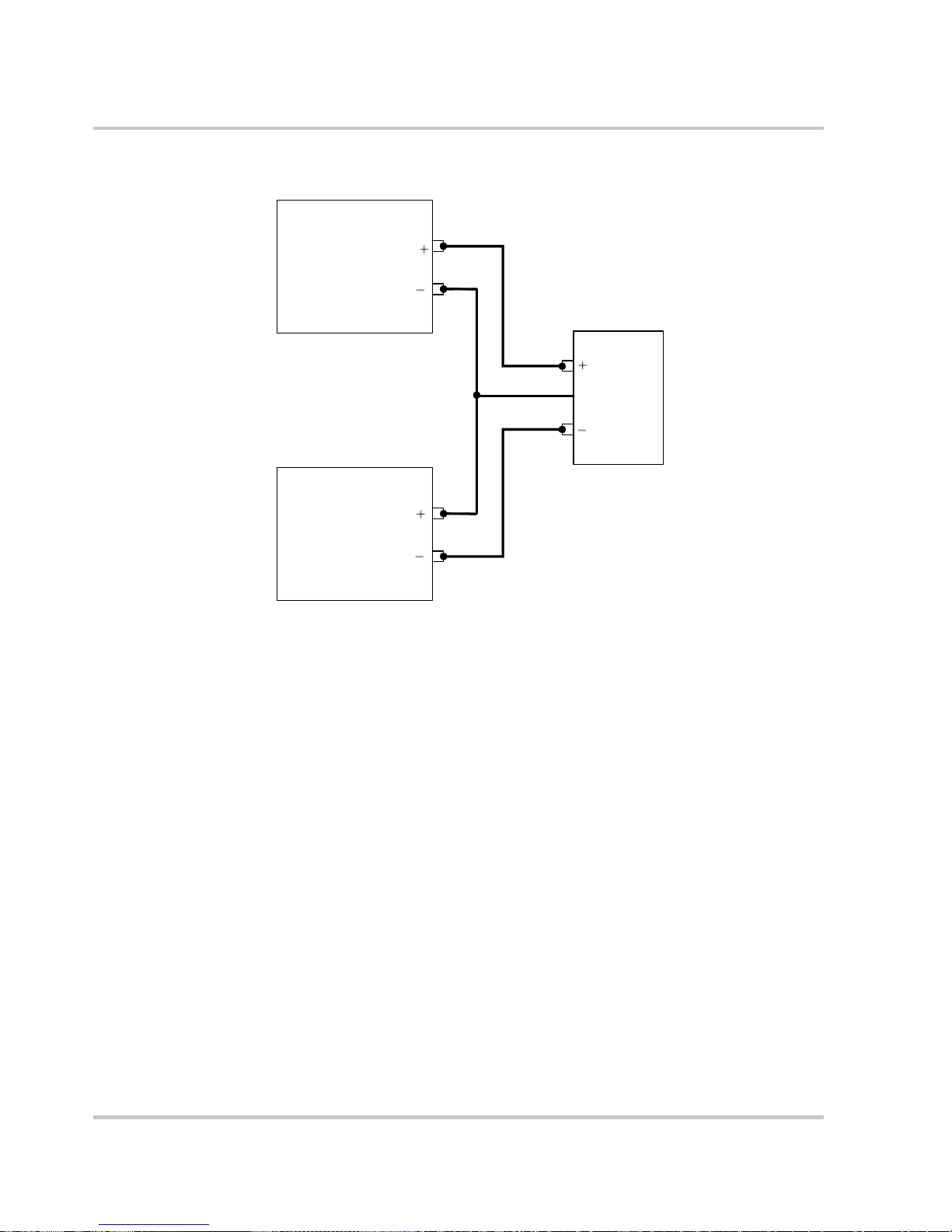
Local Operation
Power Supply
V
Common
Load
V
Power Supply
Figure 3-4
Split Supply Operation
3-38 975-0200-01-01

Using Multiple Power Supplies
–
–
Configuring Multiple Supplies for Series Operation
A maximum of two power supplies of the same rating can be connected in
series to increase the output voltage.
CAUTION
When two power supplies are connected in series, they should be programmed to
the same output voltage to prevent damage to the lower voltage supply at short
circuit condition.
Connecting to the Load in Local Sensing Mode
Connect the negative (–) output terminal of one power supply to the
positive (+) output terminal of the next power supply . See
representation of series operation.
J1.2
+LS
J1.1
+S
Figure 3-5 for a
3
Power Supply
J1.5
-LS
J1.2
+LS
Power Supply
J1.5
-LS
Figure 3-5
+
J1.6
-S
J1.1
+S
+
–
J1.6
-S
Series Operation
+
LOAD
975-0200-01-01 3-39

Local Operation
Connecting to the Load in Remote Sensing Mode
Connect the negative (–) output terminal of one power supply to the
positive (+) output terminal of the next power supply. The more positive
supply’s positive sense line should connect to the positive terminal of the
load (or distribution point). Its return sense line should connect to the
connection between the two units at the same spot as the negative
supply’s positive sense line. The return sense line of the negative supply
should be connected to the return of the load. See
CAUTION
Do not connect sense lines through relays.
Figure 3-6.
Figure 3-6
3-40 975-0200-01-01
Load Connections in Remote Sensing Mode

Using Multiple Power Supplies
Configuring Multiple Supplies for Current Sharing Operation (APG
Method)
Up to four power supplies can be connected in parallel to increase the
output current. One of the units will operate as the master unit and the
remaining units will operate as slave units controlled by the master unit.
The master unit uses the analog programming lines to set the output
voltages and currents of the slave units to match its output.
In remote digital operation, only the master unit can be programmed
remotely while the slave units that are connected remotely will only
provide voltage, current and status readback information.
Setting up the Master Unit
Set the output voltage of the master unit to the desired voltage. Program
the current set point of the master unit to the desired load current set point
divided by the number of parallel units. During operation, the master unit
operates in Constant Voltage mode, regulating the load voltage at the
programmed output voltage. Send the Current share command.
The SCPI command (s) for these instructions are:
[[:]SOURce[<channel>]]:COMBine:CSHare[:MODE]
Setting up the Slave Units
The output voltage and current of the slave units should be programmed
to maximum value. During parallel operation, the slave units operate as a
controlled current source following the master unit’s output current.
All slave units must be configured with the SCPI command to enable
current sharing.
The SCPI command (s) for these instructions are:
[[:]SOURce[<channel>]]:COMBine:CSHare[:MODE]
3
Note: The slave unit discussed here is not the same as the remote interface
slave described in chapter 5.
975-0200-01-01 3-41

Local Operation
Setting Over Voltage Protection (OVP)
The master unit’s OVP should be programmed to the desired OVP level.
The OVP of the slave units should be programmed to a higher value than
the master OVP. When the master unit shuts down, it will program the
outputs of the slave units to zero volts. If a slave unit shuts down, only
that unit would shut down and the remaining slave units would supply all
the load current if possible.
Setting Foldback Protection
Foldback protection is only available on the master units as the slaves
operate in constant current mode. They should never crossover into
constant voltage mode. If foldback is triggered on the master unit, when
its output shuts down, it will program the slave unit’ s output to zero volts.
3-42 975-0200-01-01

Using Multiple Power Supplies
Connecting to the Load in Local Sensing Mode (Parallel Control
Method)
Connect the power supplies in parallel to obtain a single output supply
with a higher output current set point. Set all of the outputs to the same
voltage before connecting the positive (+) and negative (–) terminals in
parallel. The total current available is the sum of t he maximum currents of
each power supply.
3
Figure 3-7
975-0200-01-01 3-43
Load Connections in Local Sensing Mode
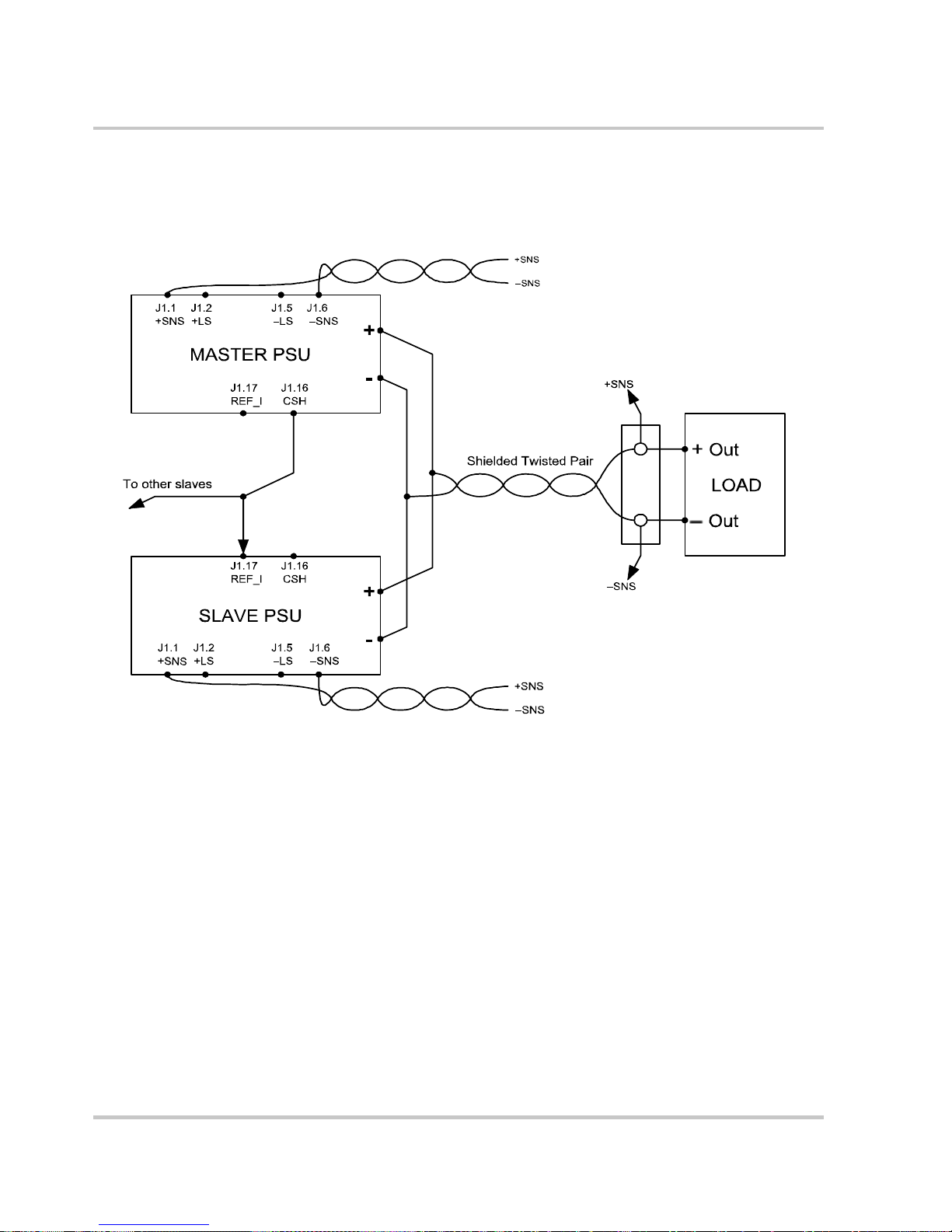
Local Operation
Connecting to the Load in Remote Sensing Mode (Parallel Control
Method)
Figure 3-8
3-44 975-0200-01-01
Load Connections in Remote Sensing Mode (Parallel Control Method)

Analog
4
Programming (APG)
and Isolated Analog
Programming (ISOL)
Chapter 4, Analog Programming (APG) and Isolated
Analog Programming (ISOL), provides information and
procedures for analog and isolated analog programming of
the power supply.

Analog Programming (APG) and Isolated Analog Programming (ISOL)
Introduction
The rear panel connectors J1 and J3 provide an option to control and
monitor the output of the power supply with analog signals. Connector J1
provides a non-isolated analog interface where all signals are referenced
to the negative output terminal of the power supply. Connector J3 is an
isolated interface and also provides an isolated auxiliary voltage output to
aid analog programming.
Analog Programming (APG) of Output Voltage and Output Current
Analog programming allows control of the power supply’s output
voltage, output current or both to be controlled from analog input sources.
As the programming source is varied within the configured analog
programming range (2–10
varies proportionally over its output range. For example, if you set the
programming scale to 10
programming pins, the power supply will be programmed to 50% of the
output capability for your power supply.
volts/kΩ max), the power supply’s output
V voltage source and apply 5 V to the
While analog programming mode is configured, you will not be able to
make adjustments to the set points from the front panel or through the
remote interfaces.
The front panel will display AnPr in the output current display when the
mode control knob is turned to VOL or CUR positions for the
parameter(s) that are configured to be controlled by analog programming.
If an adjustment of a parameter controlled by APG is attempted using a
SCPI command, a “-221 Settings Conflict” error will be pushed onto the
error queue.
Using analog programming requires that you make connections to the
Isolated Analog Programming Connector or Analog Programming
Connector on the rear panel of the power supply. Depending on your
model, see
“Rear Panel Connectors on XTR 1700 Watt” on page 1–8.
“Rear Panel Connectors on XTR 850 Watt” on page 1–6 or
4-2 975-0200-01-01

Remote Programming Options
Analog Monitor Signals
There are four monitor lines for analog programming the pin name and
the related APG mode, which are listed in
provided to give analog feedback. The output from these monitor lines is
a value scaled to the Analog Programming level set for the corresponding
analog programming type. For example, the voltage monitor and isolated
voltage monitor lines are both scaled to the analog programming level
that is set in the VAP mode.
Introduction
T able 4-1. All of these lines are
Auxiliary Outputs
Table 4-1
Related APG Mode Reference Line
Non-Isolated Voltage Analog Programming VOL_MON J1.13
Isolated Voltage Analog Programming IS_MON_VOL J3.5
Non-Isolated Current Analog Programming CUR_MON J1.14
Isolated Current Analog Programming IS_MON_CUR J3.10
Important:
supply even when the unit is not set to operate in analog programming mode.
The auxiliary outputs are an additional isolated source. The auxiliary
output has two outputs: +5
The auxiliary output operates independently of the main output. It is
enabled or disabled from the front panel by pressing the AUX ON/OFF
button. When the Aux output is enabled, the AUX ON/OFF button is
illuminated. Like the main output of the power supply, the Aux also has
the ability to Autostart at power up. See
Restart)” on page 3–15 and “Auxiliary Auto Start Mode” on page 3–16
for details on controlling this feature.
Monitor Lines
Connector
Name
Analog control monitor lines will reflect the output of the power
V output on J3.9 and a +15 V output on J3.11.
“Output Auto Start Mode (Auto
4
Table 4-2 provides a summary of the options available for programming
output voltage and current set point using an analog source.
975-0200-01-01 4-3

Analog Programming (APG) and Isolated Analog Programming (ISOL)
Table 4-2
Control of… Programming Scale
Remote Programming Options
1
For more info…
Output voltage 2–10 V Voltage source (adjustable) See page 4–10.
Current set point 2–10 V Voltage source (adjustable) See page 4–12.
Output voltage 2–10 kΩ Resistive source (adjustable) See page 4–15.
Current set point 2–10 kΩ Resistive source (adjustable) See page 4–17.
1.The resolution can be adjusted in increments of 0.1 volts.
4-4 975-0200-01-01

Analog Programming (APG) Connector J1
The APG connector is an 18-pin connector. See Figure 4-1.
The APG connector provides access to the following functions:
• Sense control
• Analog programming and monitoring.
Introduction
+SNS
+LS
-LS
-SNS
COM
VOL_PR
CUR_PR
Figure 4-1
Table 4-3
Jumper
123
APG Connector Terminals
APG Pins and Functions J1
4
Jumper
5
67
8
Pin Reference Function
910
11 12 13 14
15 16 17
18
REF_I
CSH
EXT_CC_CV
CUR_MON
VOL_MON
CUR_RES_PR
VOL_RES_PR
4
J1.1 +SNS Positive (+) Sense
J1.2 +LS Positive (+)
J1.3 –NC
J1.4 –NC
J1.5 –LS Negative (–)
J1.6 –SNS Negative (–)
J1.7 COM Analog Common Same as power supply negative sense (–SNS)
J1.8 COM Analog Common Same as power supply negative sense (–SNS)
975-0200-01-01 4-5
Local Sense}Jumper. Factory default condition.
Local Sense}Jumper. Factory default condition.
Sense

Analog Programming (APG) and Isolated Analog Programming (ISOL)
Table 4-3
APG Pins and Functions J1
Pin Reference Function
J1.9 VOL_PR Analog Voltage Programming Input
J1.10 CUR_PR Analog Current Programming Input
J1.11 VOL_RES_PR Voltage Resistive Programming
J1.12 CUR_RES_PR Current Resistive Programming
J1.13 VOL_MON Voltage Monitor. Scaled to the value of the Voltage Analog
Programming Level.
J1.14 CUR_MON Current Monitor. Scaled to the value of the Current Analog
Programming Level.
J1.15 EXT_CC_CV External CC/CV. Indicates the state of the operate mode. When
in CV mode, logic high is output and when in CC mode, logic
low is output. Logic is TTL/CMOS compatible.
J1.16 CSH Current Share. Used to hook up units for current sharing. Output
from master unit. Slave units left open.
J1.17 REF_I Current Reference Input. Slave input from current share pin on
master unit.
J1.18 NC
4-6 975-0200-01-01

Making Control Connections
CAUTION
Before making connections from external circuits to the Analog Programming
Connector, turn the front panel power switch to Off and wait until the front panel
displays are not illuminated.
CAUTION
Program/monitor signal and return are internally connected to the power supply
negative output (-S). Do not attempt to bias these away from that potential.
To connect the output wires to the APG and DC output connector:
1. Insert a 3/32 inch slot-head screwdriver into the orange-colored box
of the connector until the end of the spring is reached. See
2. Hold the connector open and insert the applicable output wire.
3. Remove the screwdriver.
Introduction
Figure 4-2.
Figure 4-2
Figure 4-3
4
Inserting Screwdriver into Spring Terminal Block
APG and DC Output Connector
975-0200-01-01 4-7

Analog Programming (APG) and Isolated Analog Programming (ISOL)
Wiring
WARNING: Shock hazard
There is a potential shock hazard at the output when using a power supply with a
rated output greater than 60
equivalent to the maximum output voltage of the power supply. For example,
select TEW, 105 °C, 600
For most connectors and jumpers, use any suitable wire such as 20 to
26
AWG stranded wire. For lowest noise performance, use shielded
twisted pair wiring of 20 to 26 AWG of the shortest length possible.
Ground the shield to pin J1.7 (analog common) on the Analog
Programming Connector or to the chassis via one of the Analog
Programming Connector screws.
V. Use load wiring with a minimum insulation rating
V wiring for use with a 600 V, 1.4 A power supply.
4-8 975-0200-01-01
 Loading...