

Page 1

Artisan Technology Group is your source for quality
new and certied-used/pre-owned equipment
• FAST SHIPPING AND
DELIVERY
• TENS OF THOUSANDS OF
IN-STOCK ITEMS
• EQUIPMENT DEMOS
• HUNDREDS OF
MANUFACTURERS
SUPPORTED
• LEASING/MONTHLY
RENTALS
• ITAR CERTIFIED
SECURE ASSET SOLUTIONS
SERVICE CENTER REPAIRS
Experienced engineers and technicians on staff
at our full-service, in-house repair center
WE BUY USED EQUIPMENT
Sell your excess, underutilized, and idle used equipment
We also offer credit for buy-backs and trade-ins
www.artisantg.com/WeBuyEquipment
REMOTE INSPECTION
Remotely inspect equipment before purchasing with
our interactive website at www.instraview.com
LOOKING FOR MORE INFORMATION?
Visit us on the web at www.artisantg.com for more
information on price quotations, drivers, technical
specications, manuals, and documentation
Contact us: (888) 88-SOURCE | sales@artisantg.com | www.artisantg.com
SM
View
Instra
Page 2
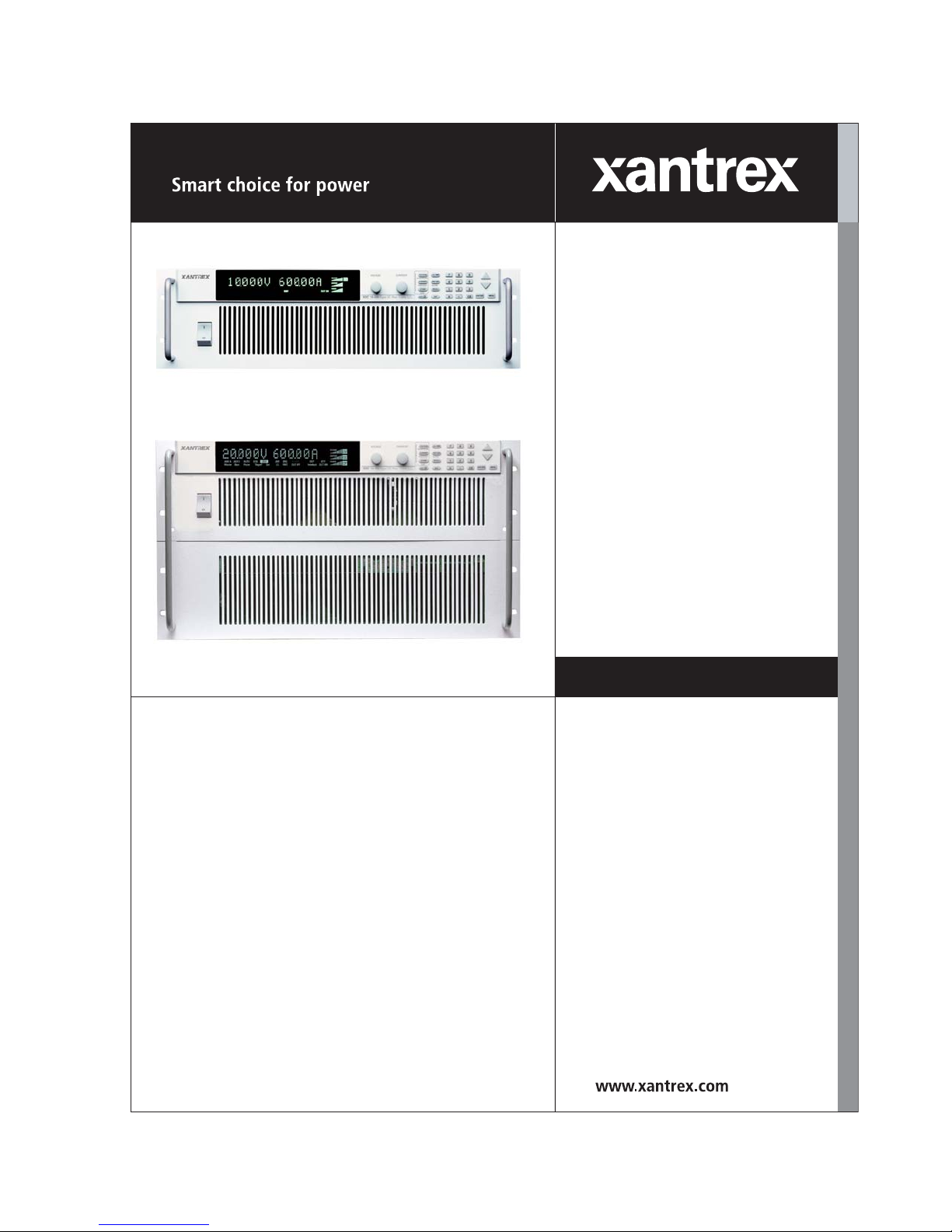
XDC 6000 Watt
and 12000 Watt Series
Digital Programmable
DC Power Supply
XDC 10-600
XDC 20-300
XDC 30-200
XDC 40-150
XDC 60-100
XDC 80-75
XDC 100-60
XDC 150-40
XDC 300-20
XDC 600-10
XDC 10-1200
XDC 20-600
XDC 30-400
XDC 40-300
XDC 60-200
XDC 80-150
XDC 100-120
XDC 150-80
XDC 300-40
XDC 600-20
Operating Manual
Artisan Technology Group - Quality Instrumentation ... Guaranteed | (888) 88-SOURCE | www.artisantg.com
Page 3

Artisan Technology Group - Quality Instrumentation ... Guaranteed | (888) 88-SOURCE | www.artisantg.com
Page 4

Operating Manual for
XDC 6000 Watt and
12000 Watt Series
Digital Programmable
DC Power Supply
Artisan Technology Group - Quality Instrumentation ... Guaranteed | (888) 88-SOURCE | www.artisantg.com
Page 5

Limited
Warranty
What does this warranty cover and how long does it last?
This Limited Warranty is provided by Xantrex Technology, Inc. (“Xantrex”) and
covers defects in workmanship and materials in your XDC 6000 Watt or
12000 Watt Series Digital DC Power Supply. This warranty lasts for a Warranty
Period of 5 years from the date of purchase at point of sale to you, the original end
user customer.
What will Xantrex do?
Xantrex will, at its option, repair or replace the defective product free of charge,
provided that you notify Xantrex of the product defect within the Warranty Period,
and provided that Xantrex through inspection establishes the existence of such a
defect and that it is covered by this Limited Warranty.
Xantrex will, at its option, use new and/or reconditioned parts in performing
warranty repair and building replacement products. Xantrex reserves the right to use
parts or products of original or improved design in the repair or replacement. If
Xantrex repairs or replaces a product, its warranty continues for the remaining
portion of the original Warranty Period or 90 days from the date of the return
shipment to the customer, whichever is greater. All replaced products and all parts
removed from repaired products become the property of Xantrex.
Xantrex covers both parts and labor necessary to repair the product, and return
shipment to the customer via a Xantrex-selected non-expedited surface freight
within the contiguous United States and Canada. Alaska and Hawaii are excluded.
Contact Xantrex Customer Service for details on freight policy for return shipments
outside of the contiguous United States and Canada.
How do you get service?
If your product requires troubleshooting or warranty service, contact your merchant.
If you are unable to contact your merchant, or the merchant is unable to provide
service, contact Xantrex directly at:
Phone: 604 422 8595
Toll Free North America: 1 800 667 8422
Fax: 604 421 3056
Email: info@xantrex.com
ii Operating Manual for XDC Series Power Supply
Artisan Technology Group - Quality Instrumentation ... Guaranteed | (888) 88-SOURCE | www.artisantg.com
Page 6

Direct returns may be performed according to the Xantrex Return Material
Authorization Policy described in your product manual. For some products, Xantrex
maintains a network of regional Authorized Service Centers. Call Xantrex or check
our website to see if your product can be repaired at one of these facilities.
In any warranty claim, dated proof of purchase must accompany the product and the
product must not have been disassembled or modified without prior written
authorization by Xantrex.
Proof of purchase may be in any one of the following forms:
• The dated purchase receipt from the original purchase of the product at point of
sale to the end user, or
• The dated dealer invoice or purchase receipt showing original equipment
manufacturer (OEM) status, or
• The dated invoice or purchase receipt showing the product exchanged under
warranty
What does this warranty not cover?
This Limited Warranty does not cover normal wear and tear of the product or costs
related to the removal, installation, or troubleshooting of the customer’s electrical
systems. This warranty does not apply to and Xantrex will not be responsible for any
defect in or damage to:
a. the product if it has been misused, neglected, improperly installed, physically
damaged or altered, either internally or externally, or damaged from improper
use or use in an unsuitable environment;
b. the product if it has been subjected to fire, water, generalized corrosion,
biological infestations, and high input voltage from lightning strikes;
c. the product if repairs have been done to it other than by Xantrex or its authorized
service centers (hereafter “ASCs”);
d. the product if it is used as a component part of a product expressly warranted by
another manufacturer;
e. the product if its original identification (trade-mark, serial number) markings
have been defaced, altered, or removed.
Release 3.0 iii
Artisan Technology Group - Quality Instrumentation ... Guaranteed | (888) 88-SOURCE | www.artisantg.com
Page 7

Disclaimer Product
THIS LIMITED WARRANTY IS THE SOLE AND EXCLUSIVE WARRANTY PROVIDED
BY XANTREX IN CONNECTION WITH YOUR XANTREX PRODUCT AND IS, WHERE
PERMITTED BY LAW, IN LIEU OF ALL OTHER WARRANTIES, CONDITIONS,
GUARANTEES, REPRESENTATIONS, OBLIGATIONS AND LIABILITIES, EXPRESS
OR IMPLIED, STATUTORY OR OTHERWISE IN CONNECTION WITH THE
PRODUCT, HOWEVER ARISING (WHETHER BY CONTRACT, TORT, NEGLIGENCE,
PRINCIPLES OF MANUFACTURER’S LIABILITY, OPERATION OF LAW, CONDUCT,
STATEMENT OR OTHERWISE), INCLUDING WITHOUT RESTRICTION ANY
IMPLIED WARRANTY OR CONDITION OF QUALITY, MERCHANTABILITY OR
FITNESS FOR A PARTICULAR PURPOSE. ANY IMPLIED WARRANTY OF
MERCHANTABILITY OR FITNESS FOR A PARTICULAR PURPOSE TO THE EXTENT
REQUIRED UNDER APPLICABLE LAW TO APPLY TO THE PRODUCT SHALL BE
LIMITED IN DURATION TO THE PERIOD STIPULATED UNDER THIS LIMITED
WARRANTY.
IN NO EVENT WILL XANTREX BE LIABLE FOR ANY SPECIAL, DIRECT, INDIRECT,
INCIDENTAL OR CONSEQUENTIAL DAMAGES, LOSSES, COSTS OR EXPENSES
HOWEVER ARISING WHETHER IN CONTRACT OR TORT INCLUDING WITHOUT
RESTRICTION ANY ECONOMIC LOSSES OF ANY KIND, ANY LOSS OR DAMAGE TO
PROPERTY, ANY PERSONAL INJURY, ANY DAMAGE OR INJURY ARISING FROM OR
AS A RESULT OF MISUSE OR ABUSE, OR THE INCORRECT INSTALLATION,
INTEGRATION OR OPERATION OF THE PRODUCT.
Exclusions If this product is a consumer product, federal law does not allow an exclusion of
implied warranties. To the extent you are entitled to implied warranties under federal
law, to the extent permitted by applicable law they are limited to the duration of this
Limited Warranty. Some states and provinces do not allow limitations or exclusions
on implied warranties or on the duration of an implied warranty or on the limitation
or exclusion of incidental or consequential damages, so the above limitation(s) or
exclusion(s) may not apply to you. This Limited Warranty gives you specific legal
rights. You may have other rights which may vary from state to state or province to
province.
iv Operating Manual for XDC Series Power Supply
Artisan Technology Group - Quality Instrumentation ... Guaranteed | (888) 88-SOURCE | www.artisantg.com
Page 8

Information WITHOUT LIMITING THE GENERALITY OF THE FOREGOING, UNLESS
SPECIFICALLY AGREED TO BY IT IN WRITING, XANTREX
a. MAKES NO WARRANTY AS TO THE ACCURACY, SUFFICIENCY OR SUITABILITY
OF ANY TECHNICAL OR OTHER INFORMATION PROVIDED IN MANUALS OR
OTHER DOCUMENTATION PROVIDED BY IT IN CONNECTION WITH THE
PRODUCT; AND
b. ASSUMES NO RESPONSIBILITY OR LIABILITY FOR LOSSES, DAMAGES,
COSTS OR EXPENSES, WHETHER SPECIAL, DIRECT, INDIRECT,
CONSEQUENTIAL OR INCIDENTAL, WHICH MIGHT ARISE OUT OF THE USE OF
SUCH INFORMATION.
THE USE OF ANY SUCH INFORMATION WILL BE ENTIRELY AT THE USER’S RISK.
WARNING:
Limitations
on Use
Please refer to your product user manual for limitations on uses of the product.
Specifically, please note that this power supply is not intended for use in connection
with life support systems and Xantrex makes no warranty or representation in
connection with any use of the product for such purposes.
Xantrex Technology, Inc.
8999 Nelson Way
Burnaby, British Columbia
Canada V5A 4B5
Information
About Your
Power
Supply
Please record the following information when you first open your Power Supply
package:
Model Number ______________________________________________
Serial Number ______________________________________________
Purchased From ______________________________________________
Purchase Date ______________________________________________
Release Release 3.0 (2002-06)
Copyright © 2002 Xantrex Technology Inc. All rights reserved.
Printed in Canada
Release 3.0 v
Artisan Technology Group - Quality Instrumentation ... Guaranteed | (888) 88-SOURCE | www.artisantg.com
Page 9
Warnings
!
!
!
and
Cautions
Power
Supply
Safety
Warnings and cautions are defined and formatted in this manual as shown below.
WARNING
Describes a potential hazard which could result in injury or death, or, a procedure
which, if not performed correctly, could result in injury or death.
CAUTION
Describes a procedure which, if not performed correctly, could result in damage
to data, equipment, or systems.
WARNING—High Energy and High Voltage
Exercise caution when using and calibrating a power supply. High energy levels
can be stored at the output voltage terminals on a power supply in normal
operation. In addition, potentially lethal voltages exist in the power circuit and on
the output and sense connectors of a power supply with a rated output greater
than 40 V. Filter capacitors store potentially dangerous energy for some time after
power is removed.
CAUTION
Operate the power supply in an environment free of flammable gases or fumes. To
ensure that the power supply’s safety features are not compromised, use the
power supply as specified in this manual and do not substitute parts or make any
unauthorized modifications. Contact the service technician for service and repair
help. Repairs must be made by experienced service technicians only.
CAUTION
For Use as a Battery Charger
When you are using any of these power supplies for battery charging applications,
it is essential to provide an appropriately sized fuse or circuit breaker in series
between the power supply output and the battery.
Installation of a protector (fuse or DC circuit breaker) rated for about 115% of the
maximum current rating of the power supply and designed specifically to interrupt
the DC voltage of the battery, will provide adequate reverse polarity current
protection. Where several power supplies are in parallel, it is best to fuse each one,
rather than one large fuse for all.
vi Operating Manual for XDC Series Power Supply
Artisan Technology Group - Quality Instrumentation ... Guaranteed | (888) 88-SOURCE | www.artisantg.com
Page 10

IEC
Symbols
Used in This
Manual
Earth (Ground) Terminal
Protective Conductor Terminal
On (Supply)
Off (Supply)
Warning (Shock Hazard)
Caution (Check manual for specific information.)
Release 3.0 vii
Artisan Technology Group - Quality Instrumentation ... Guaranteed | (888) 88-SOURCE | www.artisantg.com
Page 11

Approvals CE Mark
CE-marked units meet the following standards:
• IEC 1010-1-92 including Amendments 1 and 2:
• Overvoltage Category II
• Permanently Connected Equipment
• EN50081-2-1996 Electromagnetic Generic Emission - Industrial Equivalent
• EN50082-2-1995 Electromagnetic Compatibility Generic Immunity - Industrial
Environment
CSA Certified
CSA C22.2 No. 1010.1-92
UL Listed (pending)
Meets UL3101-1 Electrical Equipment for Laboratory Use; Part 1: General
Requirements
General safety requirements for electrical equipment intended for professional,
industrial process, and educational use, including equipment and computing devices
for: measurement and test; control; laboratory use; and accessories intended for use
with the above.
FCC Compliance
FCC Part 15 - Radio Frequency Devices - Class A Limits
Canadian EMC Requirements
The unit complies with Canadian EMC requirements of ICES-001.
viii Operating Manual for XDC Series Power Supply
Artisan Technology Group - Quality Instrumentation ... Guaranteed | (888) 88-SOURCE | www.artisantg.com
Page 12

About This Manual
Who Should Use This Manual
This manual is designed for users who understand basic electrical theory, especially
as applied to the operation of power supplies. This implies a recognition of constant
voltage and constant current operating modes and the control of input and output
power, as well as the observance of safe techniques while making connections to the
supply and any changes in settings.
Navigation
Sections
To help you locate information easily, this manual has the following:
• A Table of Contents
• A List of Figures
• A List of Tables
• An Index
Section 1: About the XDC Power Supply describes the power supply features,
front panel controls, front panel display, and rear panel connectors. It also gives an
overview of operation.
Section 2: Installation describes how to mount the power supply, how to
connect it, and how to run initial self-tests.
Section 3: Operation describes basic operation and functions carried out from
the front panel using the function keys and menu options.
Section 4: Remote Operation explains how to hook up remote interfaces and
how to send commands to the power supply through the SCPI programming
language.
Section 5: Current Sharing (6000 Watt only) explains how to configure the
power supply for current sharing among units connected in parallel.
Appendix A: Calibration describes calibration parameters and procedures.
Release 3.0 ix
Artisan Technology Group - Quality Instrumentation ... Guaranteed | (888) 88-SOURCE | www.artisantg.com
Page 13

About This Manual
Revisions
Appendix B: SCPI Command Reference describes the Standard Commands
for Programmable Instruments (SCPI) commands supported by this model.
Appendix C: Error Messages describes the error messages that could appear
during operation.
Appendix D: GPIB describes the General Purpose Interface Bus (GPIB)
commands and lines supported by this model.
Appendix E: Specifications and Characteristics provides electrical and
mechanical specifications.
The current release of this manual is listed below. Updates may be issued as an
addendum.
Release 3.0 (2002-06)
x Operating Manual for XDC Series Power Supply
Artisan Technology Group - Quality Instrumentation ... Guaranteed | (888) 88-SOURCE | www.artisantg.com
Page 14

Contents
About This Manual . . . . . . . . . . . . . . . . . . . . . . . . . . . . . . . . . . . . . . . . . . . . . . . . . . . .ix
List of Tables . . . . . . . . . . . . . . . . . . . . . . . . . . . . . . . . . . . . . . . . . . . . . . . . . . . . . . xvii
List of Figures. . . . . . . . . . . . . . . . . . . . . . . . . . . . . . . . . . . . . . . . . . . . . . . . . . . . . . . xix
Section 1. About The XDC Power Supply
Overview . . . . . . . . . . . . . . . . . . . . . . . . . . . . . . . . . . . . . . . . . . . . . . . . . . . . . . . . . . 21
Features . . . . . . . . . . . . . . . . . . . . . . . . . . . . . . . . . . . . . . . . . . . . . . . . . . . . . . 21
Front Panel. . . . . . . . . . . . . . . . . . . . . . . . . . . . . . . . . . . . . . . . . . . . . . . . . . . . . . . . . 22
Display . . . . . . . . . . . . . . . . . . . . . . . . . . . . . . . . . . . . . . . . . . . . . . . . . . . . . . . . . . . . 28
Status Annunciators . . . . . . . . . . . . . . . . . . . . . . . . . . . . . . . . . . . . . . . . . . . . . . . . . . 28
Rear Panel . . . . . . . . . . . . . . . . . . . . . . . . . . . . . . . . . . . . . . . . . . . . . . . . . . . . . . . . . 30
Overview of Operation . . . . . . . . . . . . . . . . . . . . . . . . . . . . . . . . . . . . . . . . . . . . . . . . 31
Power ON . . . . . . . . . . . . . . . . . . . . . . . . . . . . . . . . . . . . . . . . . . . . . . . . . . . . . 31
Control Modes . . . . . . . . . . . . . . . . . . . . . . . . . . . . . . . . . . . . . . . . . . . . . . . . . . 31
Section 2. Installation
Overview . . . . . . . . . . . . . . . . . . . . . . . . . . . . . . . . . . . . . . . . . . . . . . . . . . . . . . . . . . 33
Basic Setup Procedure . . . . . . . . . . . . . . . . . . . . . . . . . . . . . . . . . . . . . . . . . . . . . . . 33
Inspection, Cleaning, and Packaging. . . . . . . . . . . . . . . . . . . . . . . . . . . . . . . . . . . . . 34
Initial Inspection. . . . . . . . . . . . . . . . . . . . . . . . . . . . . . . . . . . . . . . . . . . . . . . . . 34
Maintenance . . . . . . . . . . . . . . . . . . . . . . . . . . . . . . . . . . . . . . . . . . . . . . . . . . . 34
Returning Power Supplies to the Manufacturer . . . . . . . . . . . . . . . . . . . . . . . . . . . . . 35
Return Material Authorization Policy . . . . . . . . . . . . . . . . . . . . . . . . . . . . . . . . . 35
Packaging for Shipping or Storage . . . . . . . . . . . . . . . . . . . . . . . . . . . . . . . . . . 36
Location, Mounting, and Ventilation . . . . . . . . . . . . . . . . . . . . . . . . . . . . . . . . . . . . . . 37
Rack Mounting. . . . . . . . . . . . . . . . . . . . . . . . . . . . . . . . . . . . . . . . . . . . . . . . . . 37
Ventilation . . . . . . . . . . . . . . . . . . . . . . . . . . . . . . . . . . . . . . . . . . . . . . . . . . . . . 39
AC Input Power . . . . . . . . . . . . . . . . . . . . . . . . . . . . . . . . . . . . . . . . . . . . . . . . . . . . . 40
AC Input Connector . . . . . . . . . . . . . . . . . . . . . . . . . . . . . . . . . . . . . . . . . . . . . . 40
AC Input Wire . . . . . . . . . . . . . . . . . . . . . . . . . . . . . . . . . . . . . . . . . . . . . . . . . . 41
AC Wire Input Connection for 6000 W . . . . . . . . . . . . . . . . . . . . . . . . . . . . . . . 41
AC Wire Input Connection for 12000 W . . . . . . . . . . . . . . . . . . . . . . . . . . . . . . 43
Basic Checks or Self-Tests . . . . . . . . . . . . . . . . . . . . . . . . . . . . . . . . . . . . . . . . . . . . 45
Equipment Required . . . . . . . . . . . . . . . . . . . . . . . . . . . . . . . . . . . . . . . . . . . . . 45
Display Test. . . . . . . . . . . . . . . . . . . . . . . . . . . . . . . . . . . . . . . . . . . . . . . . . . . . 45
Power ON Check. . . . . . . . . . . . . . . . . . . . . . . . . . . . . . . . . . . . . . . . . . . . . . . . 46
Voltage Mode Operation Check . . . . . . . . . . . . . . . . . . . . . . . . . . . . . . . . . . . . 46
Current Mode Operation Check. . . . . . . . . . . . . . . . . . . . . . . . . . . . . . . . . . . . . 47
Load Wiring . . . . . . . . . . . . . . . . . . . . . . . . . . . . . . . . . . . . . . . . . . . . . . . . . . . . . . . . 48
Current Carrying Capacity . . . . . . . . . . . . . . . . . . . . . . . . . . . . . . . . . . . . . . . . . 48
Load Wiring Length for Operation with Sense Lines . . . . . . . . . . . . . . . . . . . . . 49
Noise and Impedance Effects . . . . . . . . . . . . . . . . . . . . . . . . . . . . . . . . . . . . . . 49
Release 3.0 xi
Artisan Technology Group - Quality Instrumentation ... Guaranteed | (888) 88-SOURCE | www.artisantg.com
Page 15

Contents
Load Connections . . . . . . . . . . . . . . . . . . . . . . . . . . . . . . . . . . . . . . . . . . . . . . . . . . . 50
Remote Sensing . . . . . . . . . . . . . . . . . . . . . . . . . . . . . . . . . . . . . . . . . . . . . . . . . . . . 56
Section 3. Operation
Overview . . . . . . . . . . . . . . . . . . . . . . . . . . . . . . . . . . . . . . . . . . . . . . . . . . . . . . . . . . 57
Power Supply Operating States. . . . . . . . . . . . . . . . . . . . . . . . . . . . . . . . . . . . . . . . . 58
Power Supply Regulation Modes. . . . . . . . . . . . . . . . . . . . . . . . . . . . . . . . . . . . . . . . 59
Remote Control Modes . . . . . . . . . . . . . . . . . . . . . . . . . . . . . . . . . . . . . . . . . . . . . . . 60
Front Panel Controls . . . . . . . . . . . . . . . . . . . . . . . . . . . . . . . . . . . . . . . . . . . . . . . . . 61
Power Supply Operation . . . . . . . . . . . . . . . . . . . . . . . . . . . . . . . . . . . . . . . . . . . . . . 64
Wire Size. . . . . . . . . . . . . . . . . . . . . . . . . . . . . . . . . . . . . . . . . . . . . . . . . . . . . . 50
Isolation. . . . . . . . . . . . . . . . . . . . . . . . . . . . . . . . . . . . . . . . . . . . . . . . . . . . . . . 50
Single Load . . . . . . . . . . . . . . . . . . . . . . . . . . . . . . . . . . . . . . . . . . . . . . . . . . . . 51
Multiple Loads . . . . . . . . . . . . . . . . . . . . . . . . . . . . . . . . . . . . . . . . . . . . . . . . . . 52
Output Strain Relief/Cover . . . . . . . . . . . . . . . . . . . . . . . . . . . . . . . . . . . . . . . . 53
Powering ON the Power Supply . . . . . . . . . . . . . . . . . . . . . . . . . . . . . . . . . . . . 57
Powering OFF the Power Supply . . . . . . . . . . . . . . . . . . . . . . . . . . . . . . . . . . . 58
Power-On . . . . . . . . . . . . . . . . . . . . . . . . . . . . . . . . . . . . . . . . . . . . . . . . . . . . . 58
Output Shutdown. . . . . . . . . . . . . . . . . . . . . . . . . . . . . . . . . . . . . . . . . . . . . . . . 58
Soft Start . . . . . . . . . . . . . . . . . . . . . . . . . . . . . . . . . . . . . . . . . . . . . . . . . . . . . . 58
Normal Operation . . . . . . . . . . . . . . . . . . . . . . . . . . . . . . . . . . . . . . . . . . . . . . . 58
Calibration . . . . . . . . . . . . . . . . . . . . . . . . . . . . . . . . . . . . . . . . . . . . . . . . . . . . . 58
Constant Voltage (CV) . . . . . . . . . . . . . . . . . . . . . . . . . . . . . . . . . . . . . . . . . . . 59
Constant Current (CC) . . . . . . . . . . . . . . . . . . . . . . . . . . . . . . . . . . . . . . . . . . . 59
Constant Power (CP) . . . . . . . . . . . . . . . . . . . . . . . . . . . . . . . . . . . . . . . . . . . . 59
Automatic Mode Crossover. . . . . . . . . . . . . . . . . . . . . . . . . . . . . . . . . . . . . . . . 59
Function Keys . . . . . . . . . . . . . . . . . . . . . . . . . . . . . . . . . . . . . . . . . . . . . . . . . . 61
Menu Navigation . . . . . . . . . . . . . . . . . . . . . . . . . . . . . . . . . . . . . . . . . . . . . . . . 62
Top Level Menu Items. . . . . . . . . . . . . . . . . . . . . . . . . . . . . . . . . . . . . . . . . . . . 62
Control Knobs . . . . . . . . . . . . . . . . . . . . . . . . . . . . . . . . . . . . . . . . . . . . . . . . . . 63
Set Voltage . . . . . . . . . . . . . . . . . . . . . . . . . . . . . . . . . . . . . . . . . . . . . . . . . . . . 64
Set Current . . . . . . . . . . . . . . . . . . . . . . . . . . . . . . . . . . . . . . . . . . . . . . . . . . . . 64
Set Power . . . . . . . . . . . . . . . . . . . . . . . . . . . . . . . . . . . . . . . . . . . . . . . . . . . . . 65
Turn Output On or Off . . . . . . . . . . . . . . . . . . . . . . . . . . . . . . . . . . . . . . . . . . . . 65
Set Output Protection . . . . . . . . . . . . . . . . . . . . . . . . . . . . . . . . . . . . . . . . . . . . 65
Set Shutdown Recovery for AC Off and OTP . . . . . . . . . . . . . . . . . . . . . . . . . . 71
Respond to Alarms . . . . . . . . . . . . . . . . . . . . . . . . . . . . . . . . . . . . . . . . . . . . . . 72
Set Up Remote Control . . . . . . . . . . . . . . . . . . . . . . . . . . . . . . . . . . . . . . . . . . . 74
Toggle Local/Remote . . . . . . . . . . . . . . . . . . . . . . . . . . . . . . . . . . . . . . . . . . . . 74
Select Remote Control Source . . . . . . . . . . . . . . . . . . . . . . . . . . . . . . . . . . . . . 75
Configure Remote Control Source . . . . . . . . . . . . . . . . . . . . . . . . . . . . . . . . . . 76
Store User Settings . . . . . . . . . . . . . . . . . . . . . . . . . . . . . . . . . . . . . . . . . . . . . . 77
Change Stored Settings . . . . . . . . . . . . . . . . . . . . . . . . . . . . . . . . . . . . . . . . . . 78
Recall Settings . . . . . . . . . . . . . . . . . . . . . . . . . . . . . . . . . . . . . . . . . . . . . . . . . 79
Read Error Messages . . . . . . . . . . . . . . . . . . . . . . . . . . . . . . . . . . . . . . . . . . . . 82
Configure User Lines. . . . . . . . . . . . . . . . . . . . . . . . . . . . . . . . . . . . . . . . . . . . . 83
Configure Power ON Settings . . . . . . . . . . . . . . . . . . . . . . . . . . . . . . . . . . . . . . 84
xii
Artisan Technology Group - Quality Instrumentation ... Guaranteed | (888) 88-SOURCE | www.artisantg.com
Operating Manual for XDC Series Power Supply
Page 16

Program Auto Sequence . . . . . . . . . . . . . . . . . . . . . . . . . . . . . . . . . . . . . . . . . . 87
Programming a Sequence . . . . . . . . . . . . . . . . . . . . . . . . . . . . . . . . . . . . . . . . . 88
Deleting a Sequence . . . . . . . . . . . . . . . . . . . . . . . . . . . . . . . . . . . . . . . . . . . . . 91
Editing a Sequence Step . . . . . . . . . . . . . . . . . . . . . . . . . . . . . . . . . . . . . . . . . .92
Inserting a Sequence Step. . . . . . . . . . . . . . . . . . . . . . . . . . . . . . . . . . . . . . . . . 93
Deleting a Sequence Step . . . . . . . . . . . . . . . . . . . . . . . . . . . . . . . . . . . . . . . . . 94
Editing Repeat Times of a Sequence. . . . . . . . . . . . . . . . . . . . . . . . . . . . . . . . . 95
Editing Trigger Source of a Sequence . . . . . . . . . . . . . . . . . . . . . . . . . . . . . . . .96
Using Auto Sequencing . . . . . . . . . . . . . . . . . . . . . . . . . . . . . . . . . . . . . . . . . . . 97
Configure Display. . . . . . . . . . . . . . . . . . . . . . . . . . . . . . . . . . . . . . . . . . . . . . . . 98
Lock Out Control Knobs. . . . . . . . . . . . . . . . . . . . . . . . . . . . . . . . . . . . . . . . . . . 98
Set V, I, and P Limits . . . . . . . . . . . . . . . . . . . . . . . . . . . . . . . . . . . . . . . . . . . . 100
Slew Rate. . . . . . . . . . . . . . . . . . . . . . . . . . . . . . . . . . . . . . . . . . . . . . . . . . . . . 102
View Model Information . . . . . . . . . . . . . . . . . . . . . . . . . . . . . . . . . . . . . . . . . . 104
Default Display . . . . . . . . . . . . . . . . . . . . . . . . . . . . . . . . . . . . . . . . . . . . . . . . . . . . . 104
View Power Output . . . . . . . . . . . . . . . . . . . . . . . . . . . . . . . . . . . . . . . . . . . . . 104
Monitor Status . . . . . . . . . . . . . . . . . . . . . . . . . . . . . . . . . . . . . . . . . . . . . . . . . 104
Section 4. Remote Operation
Overview. . . . . . . . . . . . . . . . . . . . . . . . . . . . . . . . . . . . . . . . . . . . . . . . . . . . . . . . . . 105
Making Connections for Remote Control . . . . . . . . . . . . . . . . . . . . . . . . . . . . . . . . .107
Remote Analog Operation . . . . . . . . . . . . . . . . . . . . . . . . . . . . . . . . . . . . . . . . . . . . 108
Analog Connections . . . . . . . . . . . . . . . . . . . . . . . . . . . . . . . . . . . . . . . . . . . . . 108
Configure Analog Control. . . . . . . . . . . . . . . . . . . . . . . . . . . . . . . . . . . . . . . . . 110
Using Remote Analog Control . . . . . . . . . . . . . . . . . . . . . . . . . . . . . . . . . . . . . 112
Multichannel Operation (6000 Watt only) . . . . . . . . . . . . . . . . . . . . . . . . . . . . . . . . . 113
Multichannel Connections . . . . . . . . . . . . . . . . . . . . . . . . . . . . . . . . . . . . . . . . 113
Configuration . . . . . . . . . . . . . . . . . . . . . . . . . . . . . . . . . . . . . . . . . . . . . . . . . .114
Setup . . . . . . . . . . . . . . . . . . . . . . . . . . . . . . . . . . . . . . . . . . . . . . . . . . . . . . . . 114
Using Multichannel Operation . . . . . . . . . . . . . . . . . . . . . . . . . . . . . . . . . . . . . 115
Multichannel Commands . . . . . . . . . . . . . . . . . . . . . . . . . . . . . . . . . . . . . . . . . 116
Multichannel Broadcast Commands . . . . . . . . . . . . . . . . . . . . . . . . . . . . . . . . 117
Specifications. . . . . . . . . . . . . . . . . . . . . . . . . . . . . . . . . . . . . . . . . . . . . . . . . . 117
RS-232 Operation. . . . . . . . . . . . . . . . . . . . . . . . . . . . . . . . . . . . . . . . . . . . . . . . . . .118
RS-232 Connection . . . . . . . . . . . . . . . . . . . . . . . . . . . . . . . . . . . . . . . . . . . . . 118
Configuration . . . . . . . . . . . . . . . . . . . . . . . . . . . . . . . . . . . . . . . . . . . . . . . . . .118
Using RS-232. . . . . . . . . . . . . . . . . . . . . . . . . . . . . . . . . . . . . . . . . . . . . . . . . . 119
GPIB Operation . . . . . . . . . . . . . . . . . . . . . . . . . . . . . . . . . . . . . . . . . . . . . . . . . . . .120
GPIB Connection . . . . . . . . . . . . . . . . . . . . . . . . . . . . . . . . . . . . . . . . . . . . . . .120
Configuration . . . . . . . . . . . . . . . . . . . . . . . . . . . . . . . . . . . . . . . . . . . . . . . . . .121
Using GPIB . . . . . . . . . . . . . . . . . . . . . . . . . . . . . . . . . . . . . . . . . . . . . . . . . . . 122
SCPI Commands for Digital Interfaces. . . . . . . . . . . . . . . . . . . . . . . . . . . . . . . . . . . 123
Set Up Power ON Defaults . . . . . . . . . . . . . . . . . . . . . . . . . . . . . . . . . . . . . . . 123
Power On Output State . . . . . . . . . . . . . . . . . . . . . . . . . . . . . . . . . . . . . . . . . . 125
Store User Settings . . . . . . . . . . . . . . . . . . . . . . . . . . . . . . . . . . . . . . . . . . . . . 127
Change Remote/Local Control of Power Supply . . . . . . . . . . . . . . . . . . . . . . . 128
Contents
Release 3.0 xiii
Artisan Technology Group - Quality Instrumentation ... Guaranteed | (888) 88-SOURCE | www.artisantg.com
Page 17

Contents
Enable Output . . . . . . . . . . . . . . . . . . . . . . . . . . . . . . . . . . . . . . . . . . . . . . . . . 128
Program V,I,P . . . . . . . . . . . . . . . . . . . . . . . . . . . . . . . . . . . . . . . . . . . . . . . . . 128
Configure V, I, P Protection Limits . . . . . . . . . . . . . . . . . . . . . . . . . . . . . . . . . 130
Configure Other Protection Mechanisms . . . . . . . . . . . . . . . . . . . . . . . . . . . . 132
Clear Protection Event . . . . . . . . . . . . . . . . . . . . . . . . . . . . . . . . . . . . . . . . . . 134
View Power Supply Output . . . . . . . . . . . . . . . . . . . . . . . . . . . . . . . . . . . . . . . 134
Configure Auxiliary Status Lines . . . . . . . . . . . . . . . . . . . . . . . . . . . . . . . . . . . 134
Read Error Messages . . . . . . . . . . . . . . . . . . . . . . . . . . . . . . . . . . . . . . . . . . . 135
Triggering Commands. . . . . . . . . . . . . . . . . . . . . . . . . . . . . . . . . . . . . . . . . . . 136
Auto Sequencing . . . . . . . . . . . . . . . . . . . . . . . . . . . . . . . . . . . . . . . . . . . . . . . 136
Programming Sequences . . . . . . . . . . . . . . . . . . . . . . . . . . . . . . . . . . . . . . . . 138
Auto Sequence Operation . . . . . . . . . . . . . . . . . . . . . . . . . . . . . . . . . . . . . . . . 140
Slew Rate . . . . . . . . . . . . . . . . . . . . . . . . . . . . . . . . . . . . . . . . . . . . . . . . . . . . 141
Identification Query . . . . . . . . . . . . . . . . . . . . . . . . . . . . . . . . . . . . . . . . . . . . . 142
Option Identification Query . . . . . . . . . . . . . . . . . . . . . . . . . . . . . . . . . . . . . . . 142
SCPI Version Query . . . . . . . . . . . . . . . . . . . . . . . . . . . . . . . . . . . . . . . . . . . . 142
Status Registers . . . . . . . . . . . . . . . . . . . . . . . . . . . . . . . . . . . . . . . . . . . . . . . 142
Status Register Commands . . . . . . . . . . . . . . . . . . . . . . . . . . . . . . . . . . . . . . 157
Section 5. Current Sharing (6000 Watt only)
Overview . . . . . . . . . . . . . . . . . . . . . . . . . . . . . . . . . . . . . . . . . . . . . . . . . . . . . . . . . 173
Theory of Operation . . . . . . . . . . . . . . . . . . . . . . . . . . . . . . . . . . . . . . . . . . . . 173
Configure Current Share . . . . . . . . . . . . . . . . . . . . . . . . . . . . . . . . . . . . . . . . . 174
Setup Current Sharing Network . . . . . . . . . . . . . . . . . . . . . . . . . . . . . . . . . . . 175
Operation . . . . . . . . . . . . . . . . . . . . . . . . . . . . . . . . . . . . . . . . . . . . . . . . . . . . . . . . . 176
Errors. . . . . . . . . . . . . . . . . . . . . . . . . . . . . . . . . . . . . . . . . . . . . . . . . . . . . . . . 176
Specifications . . . . . . . . . . . . . . . . . . . . . . . . . . . . . . . . . . . . . . . . . . . . . . . . . 177
Appendix A. Calibration
Overview . . . . . . . . . . . . . . . . . . . . . . . . . . . . . . . . . . . . . . . . . . . . . . . . . . . . . . . . . 179
Entering Calibration Mode . . . . . . . . . . . . . . . . . . . . . . . . . . . . . . . . . . . . . . . . . . . . 179
Front Panel . . . . . . . . . . . . . . . . . . . . . . . . . . . . . . . . . . . . . . . . . . . . . . . . . . . 180
SCPI . . . . . . . . . . . . . . . . . . . . . . . . . . . . . . . . . . . . . . . . . . . . . . . . . . . . . . . . 181
Security code. . . . . . . . . . . . . . . . . . . . . . . . . . . . . . . . . . . . . . . . . . . . . . . . . . 181
Setup and Equipment . . . . . . . . . . . . . . . . . . . . . . . . . . . . . . . . . . . . . . . . . . . . . . . 182
Front Panel Calibration Procedure. . . . . . . . . . . . . . . . . . . . . . . . . . . . . . . . . . . . . . 183
Output Voltage . . . . . . . . . . . . . . . . . . . . . . . . . . . . . . . . . . . . . . . . . . . . . . . . 183
Output Current. . . . . . . . . . . . . . . . . . . . . . . . . . . . . . . . . . . . . . . . . . . . . . . . . 183
Analog Programming Interface 0-5V Range . . . . . . . . . . . . . . . . . . . . . . . . . . 184
Analog Programming Interface 0-10V Range . . . . . . . . . . . . . . . . . . . . . . . . . 187
Remote Interface Calibration Procedure . . . . . . . . . . . . . . . . . . . . . . . . . . . . . . . . . 187
Output Voltage . . . . . . . . . . . . . . . . . . . . . . . . . . . . . . . . . . . . . . . . . . . . . . . . 187
Output Current. . . . . . . . . . . . . . . . . . . . . . . . . . . . . . . . . . . . . . . . . . . . . . . . . 187
Analog Programming Interface 0-5V Range . . . . . . . . . . . . . . . . . . . . . . . . . . 188
Analog Programming Interface 0-10V Range . . . . . . . . . . . . . . . . . . . . . . . . . 191
Exit calibration mode . . . . . . . . . . . . . . . . . . . . . . . . . . . . . . . . . . . . . . . . . . . . . . . . 192
Restore Factory Calibration . . . . . . . . . . . . . . . . . . . . . . . . . . . . . . . . . . . . . . . . . . . 192
xiv
Operating Manual for XDC Series Power Supply
Artisan Technology Group - Quality Instrumentation ... Guaranteed | (888) 88-SOURCE | www.artisantg.com
Page 18

Appendix B. SCPI Command Reference
Overview. . . . . . . . . . . . . . . . . . . . . . . . . . . . . . . . . . . . . . . . . . . . . . . . . . . . . . . . . . 193
Codes and Standards. . . . . . . . . . . . . . . . . . . . . . . . . . . . . . . . . . . . . . . . . . . . . . . . 193
IEEE 488.2 Requirements . . . . . . . . . . . . . . . . . . . . . . . . . . . . . . . . . . . . . . . . 193
SCPI Requirements . . . . . . . . . . . . . . . . . . . . . . . . . . . . . . . . . . . . . . . . . . . . . 193
IEEE-488.2/SCPI Syntax and Style . . . . . . . . . . . . . . . . . . . . . . . . . . . . . . . . . . . . . 194
Parameters. . . . . . . . . . . . . . . . . . . . . . . . . . . . . . . . . . . . . . . . . . . . . . . . . . . . 194
SCPI Command Hierarchy . . . . . . . . . . . . . . . . . . . . . . . . . . . . . . . . . . . . . . . . . . . . 194
Using SCPI Commands . . . . . . . . . . . . . . . . . . . . . . . . . . . . . . . . . . . . . . . . . . . . . . 195
Using Minimum and Maximum. . . . . . . . . . . . . . . . . . . . . . . . . . . . . . . . . . . . . 196
Using Queries . . . . . . . . . . . . . . . . . . . . . . . . . . . . . . . . . . . . . . . . . . . . . . . . .196
Terminating Characters . . . . . . . . . . . . . . . . . . . . . . . . . . . . . . . . . . . . . . . . . . 196
Common Commands . . . . . . . . . . . . . . . . . . . . . . . . . . . . . . . . . . . . . . . . . . . .196
Parameter Types . . . . . . . . . . . . . . . . . . . . . . . . . . . . . . . . . . . . . . . . . . . . . . . . . . . 197
Boolean Parameters . . . . . . . . . . . . . . . . . . . . . . . . . . . . . . . . . . . . . . . . . . . . 197
Discrete Parameters . . . . . . . . . . . . . . . . . . . . . . . . . . . . . . . . . . . . . . . . . . . . 197
Numeric Parameters . . . . . . . . . . . . . . . . . . . . . . . . . . . . . . . . . . . . . . . . . . . . 197
String Parameters . . . . . . . . . . . . . . . . . . . . . . . . . . . . . . . . . . . . . . . . . . . . . .197
SCPI Command Summary . . . . . . . . . . . . . . . . . . . . . . . . . . . . . . . . . . . . . . . . . . . . 198
Notations Used in the Tables. . . . . . . . . . . . . . . . . . . . . . . . . . . . . . . . . . . . . . 198
Expressions . . . . . . . . . . . . . . . . . . . . . . . . . . . . . . . . . . . . . . . . . . . . . . . . . . . . . . . 213
Contents
Appendix C. Error Messages
Overview. . . . . . . . . . . . . . . . . . . . . . . . . . . . . . . . . . . . . . . . . . . . . . . . . . . . . . . . . . 215
Command Error List . . . . . . . . . . . . . . . . . . . . . . . . . . . . . . . . . . . . . . . . . . . . . . . . . 216
Execution Error List . . . . . . . . . . . . . . . . . . . . . . . . . . . . . . . . . . . . . . . . . . . . . . . . . 216
Device-Specific Error List . . . . . . . . . . . . . . . . . . . . . . . . . . . . . . . . . . . . . . . . . . . . . 218
Query Error List . . . . . . . . . . . . . . . . . . . . . . . . . . . . . . . . . . . . . . . . . . . . . . . . . . . .219
User Request Event . . . . . . . . . . . . . . . . . . . . . . . . . . . . . . . . . . . . . . . . . . . . . . . . . 219
Operation Complete Event . . . . . . . . . . . . . . . . . . . . . . . . . . . . . . . . . . . . . . . . . . . . 219
Front Pane0l Error Codes. . . . . . . . . . . . . . . . . . . . . . . . . . . . . . . . . . . . . . . . . . . . . 220
CPU Error Codes . . . . . . . . . . . . . . . . . . . . . . . . . . . . . . . . . . . . . . . . . . . . . . . . . . .220
Analog Programming Interface Error codes . . . . . . . . . . . . . . . . . . . . . . . . . . . . . . .220
Auto Sequencing Error Codes . . . . . . . . . . . . . . . . . . . . . . . . . . . . . . . . . . . . . . . . . 220
CANbus Error Codes . . . . . . . . . . . . . . . . . . . . . . . . . . . . . . . . . . . . . . . . . . . . . . . . 221
Multichannel Error Codes . . . . . . . . . . . . . . . . . . . . . . . . . . . . . . . . . . . . . . . . . . . . . 221
Current Share Error Codes. . . . . . . . . . . . . . . . . . . . . . . . . . . . . . . . . . . . . . . . . . . . 222
Release 3.0 xv
Artisan Technology Group - Quality Instrumentation ... Guaranteed | (888) 88-SOURCE | www.artisantg.com
Page 19

Contents
Appendix D. GPIB
Overview . . . . . . . . . . . . . . . . . . . . . . . . . . . . . . . . . . . . . . . . . . . . . . . . . . . . . . . . . 223
Codes and Standards . . . . . . . . . . . . . . . . . . . . . . . . . . . . . . . . . . . . . . . . . . . . . . . 223
Message Terminators . . . . . . . . . . . . . . . . . . . . . . . . . . . . . . . . . . . . . . . . . . . . . . . 223
Address Range . . . . . . . . . . . . . . . . . . . . . . . . . . . . . . . . . . . . . . . . . . . . . . . . . . . . 223
Primary Address . . . . . . . . . . . . . . . . . . . . . . . . . . . . . . . . . . . . . . . . . . . . . . . 223
Secondary Address. . . . . . . . . . . . . . . . . . . . . . . . . . . . . . . . . . . . . . . . . . . . . 223
Service Request and Polling . . . . . . . . . . . . . . . . . . . . . . . . . . . . . . . . . . . . . . . . . . 223
Protocol Specifications. . . . . . . . . . . . . . . . . . . . . . . . . . . . . . . . . . . . . . . . . . . . . . . 224
Multiline Control Functions . . . . . . . . . . . . . . . . . . . . . . . . . . . . . . . . . . . . . . . 224
Interface Functions . . . . . . . . . . . . . . . . . . . . . . . . . . . . . . . . . . . . . . . . . . . . . 224
Electrical Specifications . . . . . . . . . . . . . . . . . . . . . . . . . . . . . . . . . . . . . . . . . . . . . . 225
Driver Requirements . . . . . . . . . . . . . . . . . . . . . . . . . . . . . . . . . . . . . . . . . . . . 225
Mechanical Specifications . . . . . . . . . . . . . . . . . . . . . . . . . . . . . . . . . . . . . . . . . . . . 225
Performance Specifications . . . . . . . . . . . . . . . . . . . . . . . . . . . . . . . . . . . . . . . . . . . 225
Appendix E. Specifications and Characteristics
Electrical Specifications—Summary . . . . . . . . . . . . . . . . . . . . . . . . . . . . . . . . . . . . 228
AC Line Input Specifications . . . . . . . . . . . . . . . . . . . . . . . . . . . . . . . . . . . . . . . . . . 236
AC Line Input Voltage Operating Ranges . . . . . . . . . . . . . . . . . . . . . . . . . . . . 236
Output Performance Specifications . . . . . . . . . . . . . . . . . . . . . . . . . . . . . . . . . . . . . 237
Environmental Specification. . . . . . . . . . . . . . . . . . . . . . . . . . . . . . . . . . . . . . . . . . . 242
Thermal Specification . . . . . . . . . . . . . . . . . . . . . . . . . . . . . . . . . . . . . . . . . . . 242
Humidity Specification . . . . . . . . . . . . . . . . . . . . . . . . . . . . . . . . . . . . . . . . . . . 242
International Approvals . . . . . . . . . . . . . . . . . . . . . . . . . . . . . . . . . . . . . . . . . . . . . . 242
Mechanical Specification . . . . . . . . . . . . . . . . . . . . . . . . . . . . . . . . . . . . . . . . . . . . . 243
Index
xvi
Index . . . . . . . . . . . . . . . . . . . . . . . . . . . . . . . . . . . . . . . . . . . . . . . . . . . . . . . . . . . . 245
Operating Manual for XDC Series Power Supply
Artisan Technology Group - Quality Instrumentation ... Guaranteed | (888) 88-SOURCE | www.artisantg.com
Page 20

List of Tables
Table 1.1 Front Panel Functions . . . . . . . . . . . . . . . . . . . . . . . . . . . . . . . . . . . . .26
Table 2.1 Basic Setup Procedure . . . . . . . . . . . . . . . . . . . . . . . . . . . . . . . . . . . . 33
Table 2.2 AC Wire Specification for 6000 Watt units. . . . . . . . . . . . . . . . . . . . . .41
Table 2.3 AC Wire Specification for 12000 Watt units. . . . . . . . . . . . . . . . . . . . .41
Table 2.4 Current Carrying Capacity for Load Wiring . . . . . . . . . . . . . . . . . . . . . 48
Table 3.1 Settings Affected by Recall . . . . . . . . . . . . . . . . . . . . . . . . . . . . . . . . . 81
Table 4.1 User Line Pins . . . . . . . . . . . . . . . . . . . . . . . . . . . . . . . . . . . . . . . . . . 108
Table 4.2 Analog Programming Pins. . . . . . . . . . . . . . . . . . . . . . . . . . . . . . . . .109
Table 4.3 Analog Pin Connections for Power Loop Back . . . . . . . . . . . . . . . . . 110
Table 4.4 Analog Pin Connections with a Contact Closure . . . . . . . . . . . . . . . . 110
Table 4.5 CANbus Pins . . . . . . . . . . . . . . . . . . . . . . . . . . . . . . . . . . . . . . . . . . . 113
Table 4.6 RS-232 Pins. . . . . . . . . . . . . . . . . . . . . . . . . . . . . . . . . . . . . . . . . . . . 118
Table 4.7 GPIB Pins . . . . . . . . . . . . . . . . . . . . . . . . . . . . . . . . . . . . . . . . . . . . . 120
Table 4.8 Features Affected by Reset (*RST) Command . . . . . . . . . . . . . . . . . 126
Table 4.9 OPERation Status Register . . . . . . . . . . . . . . . . . . . . . . . . . . . . . . . . 145
Table 4.10 REGulating Sub-Register . . . . . . . . . . . . . . . . . . . . . . . . . . . . . . . . . 146
Table 4.11 SHUTdown Sub-Register . . . . . . . . . . . . . . . . . . . . . . . . . . . . . . . . . 146
Table 4.12 Protection SHUTdown Sub-Register . . . . . . . . . . . . . . . . . . . . . . . . . 147
Table 4.13 Remote CONtrol Sub-Register . . . . . . . . . . . . . . . . . . . . . . . . . . . . . 148
Table 4.14 Current SHare Sub-Register . . . . . . . . . . . . . . . . . . . . . . . . . . . . . . . 148
Table 4.15 QUEStionable Status Register . . . . . . . . . . . . . . . . . . . . . . . . . . . . .151
Table 4.16 VOLTage Sub-Register . . . . . . . . . . . . . . . . . . . . . . . . . . . . . . . . . . . 152
Table 4.17 CURRent Sub-Register . . . . . . . . . . . . . . . . . . . . . . . . . . . . . . . . . . . 152
Table 4.18 POWer Sub-Register. . . . . . . . . . . . . . . . . . . . . . . . . . . . . . . . . . . . . 152
Table 4.19 TEMPerature Sub-Register . . . . . . . . . . . . . . . . . . . . . . . . . . . . . . . . 153
Table 4.20 Standard Event Status Register . . . . . . . . . . . . . . . . . . . . . . . . . . . . 154
Table 4.21 Status Byte Summary Register . . . . . . . . . . . . . . . . . . . . . . . . . . . . .155
Table 4.22 Preset Values of User Configurable Registers . . . . . . . . . . . . . . . . . 157
Table B.1 IEEE 488.2 Commands . . . . . . . . . . . . . . . . . . . . . . . . . . . . . . . . . . . 199
Table B.2 Readback Commands . . . . . . . . . . . . . . . . . . . . . . . . . . . . . . . . . . . . 200
Table B.3 Commands for Output Control. . . . . . . . . . . . . . . . . . . . . . . . . . . . . . 201
Table B.4 Commands for Current Share (6000 W only) . . . . . . . . . . . . . . . . . . 202
Table B.5 Commands for Calibration. . . . . . . . . . . . . . . . . . . . . . . . . . . . . . . . .203
Table B.6 Command to Clear all Protection Mechanisms . . . . . . . . . . . . . . . . . 203
Table B.7 Commands for Fold Protection . . . . . . . . . . . . . . . . . . . . . . . . . . . . . 204
Table B.8 Commands for Triggering . . . . . . . . . . . . . . . . . . . . . . . . . . . . . . . . . 204
Table B.9 System Commands . . . . . . . . . . . . . . . . . . . . . . . . . . . . . . . . . . . . . . 204
Release 3.0 xvii
Artisan Technology Group - Quality Instrumentation ... Guaranteed | (888) 88-SOURCE | www.artisantg.com
Page 21

List of Tables
Table B.10 Status Commands . . . . . . . . . . . . . . . . . . . . . . . . . . . . . . . . . . . . . . 205
Table B.11 Protection Commands . . . . . . . . . . . . . . . . . . . . . . . . . . . . . . . . . . . 209
Table B.12 User Lines. . . . . . . . . . . . . . . . . . . . . . . . . . . . . . . . . . . . . . . . . . . . . 209
Table B.13 Output State . . . . . . . . . . . . . . . . . . . . . . . . . . . . . . . . . . . . . . . . . . . 209
Table B.14 Auto Sequence Commands . . . . . . . . . . . . . . . . . . . . . . . . . . . . . . . 210
Table B.15 Legacy Commands . . . . . . . . . . . . . . . . . . . . . . . . . . . . . . . . . . . . . . 212
Table B.16 Expressions . . . . . . . . . . . . . . . . . . . . . . . . . . . . . . . . . . . . . . . . . . . 213
Table C.1 Command Error List . . . . . . . . . . . . . . . . . . . . . . . . . . . . . . . . . . . . . 216
Table C.2 Execution Error List. . . . . . . . . . . . . . . . . . . . . . . . . . . . . . . . . . . . . . 216
Table C.3 Device-Specific Error List . . . . . . . . . . . . . . . . . . . . . . . . . . . . . . . . . 218
Table C.4 Query Error List. . . . . . . . . . . . . . . . . . . . . . . . . . . . . . . . . . . . . . . . . 219
Table C.5 User Request Event . . . . . . . . . . . . . . . . . . . . . . . . . . . . . . . . . . . . . 219
Table C.6 Operation Complete Event . . . . . . . . . . . . . . . . . . . . . . . . . . . . . . . . 219
Table C.7 Front Panel Error Codes . . . . . . . . . . . . . . . . . . . . . . . . . . . . . . . . . . 220
Table C.8 CPU Error Codes . . . . . . . . . . . . . . . . . . . . . . . . . . . . . . . . . . . . . . . 220
Table C.9 Analog Programming Interface Error code . . . . . . . . . . . . . . . . . . . . 220
Table C.10 Auto Sequencing Error Codes . . . . . . . . . . . . . . . . . . . . . . . . . . . . . 220
Table C.11 CANbus Error Codes . . . . . . . . . . . . . . . . . . . . . . . . . . . . . . . . . . . . 221
Table C.12 Multichannel Error Codes . . . . . . . . . . . . . . . . . . . . . . . . . . . . . . . . . 221
Table C.13 Current Share Error Codes. . . . . . . . . . . . . . . . . . . . . . . . . . . . . . . . 222
Table D.1 Multiline Control Functions . . . . . . . . . . . . . . . . . . . . . . . . . . . . . . . . 224
Table D.2 Interface Functions . . . . . . . . . . . . . . . . . . . . . . . . . . . . . . . . . . . . . . 224
Table D.3 Driver Types for Interface Lines . . . . . . . . . . . . . . . . . . . . . . . . . . . . 225
Table E.1 Specifications for 6000 Watt units (10V to 60V Models). . . . . . . . . . 228
Table E.2 Drift Specifications for 6000 Watt units (10V to 60V Models) . . . . . . 229
Table E.3 Specifications for 6000 Watt units (80V to 600V Models). . . . . . . . . 230
Table E.4 Drift Specifications for 6000 Watt units (80V to 600V Models) . . . . . 231
Table E.5 Specifications for 12000 Watt units (10V to 60V Models). . . . . . . . . 232
Table E.6 Drift Specifications for 12000 Watt units (10V to 60V Models) . . . . . 233
Table E.7 Specifications for 12000 Watt units (80V to 600V Models) . . . . . . . . 234
Table E.8 Drift Specifications for 12000 Watt units (80V to 600V Models) . . . . 235
Table E.9 AC Line Input Specifications. . . . . . . . . . . . . . . . . . . . . . . . . . . . . . . 236
xviii
Artisan Technology Group - Quality Instrumentation ... Guaranteed | (888) 88-SOURCE | www.artisantg.com
Operating Manual for XDC Series Power Supply
Page 22

List of Figures
Figure 1.1 Front Panel (6000 Watt) . . . . . . . . . . . . . . . . . . . . . . . . . . . . . . . . . . . 22
Figure 1.2 Front Panel (12000 Watt) . . . . . . . . . . . . . . . . . . . . . . . . . . . . . . . . . . 23
Figure 1.3 Keypad . . . . . . . . . . . . . . . . . . . . . . . . . . . . . . . . . . . . . . . . . . . . . . . . 24
Figure 1.4 Front Panel Display . . . . . . . . . . . . . . . . . . . . . . . . . . . . . . . . . . . . . . . 28
Figure 1.5 Front Panel Display, Status Annunciators . . . . . . . . . . . . . . . . . . . . . . 28
Figure 1.6 Rear Panel (6000 Watt low and medium output shown) . . . . . . . . . . . 30
Figure 2.1 Typical Box Label for Storage . . . . . . . . . . . . . . . . . . . . . . . . . . . . . . . 36
Figure 2.2 Unpacking the Power Supply (6000 Watt shown) . . . . . . . . . . . . . . . . 38
Figure 2.3 Mounting the Power Supply in the Rack With Support Rails . . . . . . . . 39
Figure 2.4 AC Input Connector for 6000 Watt units . . . . . . . . . . . . . . . . . . . . . . . 40
Figure 2.5 Attaching the AC Input Wires for 6000 Watt units . . . . . . . . . . . . . . . . 42
Figure 2.6 Attaching the AC Input Wires for 12000 Watt units . . . . . . . . . . . . . . . 44
Figure 2.7 Fastening the Output Wires (6000 Watt) . . . . . . . . . . . . . . . . . . . . . . . 52
Figure 2.8 Output Bus Bar Cover for 6000 Watt units . . . . . . . . . . . . . . . . . . . . . 53
Figure 2.9 Output for 12000 Watt units (Low and Medium Voltage). . . . . . . . . . . 53
Figure 2.10 Output Cover with Strain Relief for 6000 Watt units . . . . . . . . . . . . . . 54
Figure 2.11 Output for 12000 Watt units (High Voltage 300–600V) . . . . . . . . . . . . 55
Figure 4.1 View of Remote Interface Connections . . . . . . . . . . . . . . . . . . . . . . . 107
Figure 4.2 Schematic For User Line Interface . . . . . . . . . . . . . . . . . . . . . . . . . . 109
Figure 4.3 Connections for Multichannel Operation . . . . . . . . . . . . . . . . . . . . . . 115
Figure 4.4 Operation Status Registers . . . . . . . . . . . . . . . . . . . . . . . . . . . . . . . . 144
Figure 4.5 Questionable Status Registers . . . . . . . . . . . . . . . . . . . . . . . . . . . . . 150
Figure 4.6 IEEE 488.2 Status Register and Status Byte. . . . . . . . . . . . . . . . . . .153
Figure 5.1 Connections for Current Share Operation . . . . . . . . . . . . . . . . . . . . . 173
Figure E.1 Power Supply Dimensions (6000 Watt unit) . . . . . . . . . . . . . . . . . . . 243
Figure E.2 Power Supply Dimensions (12000 Watt unit) . . . . . . . . . . . . . . . . . . 244
Release 3.0 xix
Artisan Technology Group - Quality Instrumentation ... Guaranteed | (888) 88-SOURCE | www.artisantg.com
Page 23

List of Figures
xx
Artisan Technology Group - Quality Instrumentation ... Guaranteed | (888) 88-SOURCE | www.artisantg.com
Operating Manual for XDC Series Power Supply
Page 24

Section 1. About The XDC Power Supply
Overview
The XDC Series of digital, programmable DC power supplies is designed for use in
OEM, ATE, burn-in, magnet charging, and other high power systems for a broad
range of applications. The XDC uses our newly developed digital technology which,
combined with “Soft Switching,” provides superior performance and a high level of
user control through both front panel and remote interfaces.
Features
• Digital processing for highly accurate control
• Ten, 99-step auto sequences for easy bench-top programming of complex test
routines
• Ten stored settings
• Zero voltage (soft) switching for low noise output, improved efficiency and
higher reliability
• Active Power Factor Correction (PFC) for lower input current draw and lower
current harmonic generation
• Remote voltage sense with 5V line drop compensation
• Automatic Voltage/Current mode crossover
• Constant power mode
• Seven load protection mechanisms
• Alarms and messages for over- and under-programmed trip points
• Auxiliary status lines for monitoring power supply conditions
• Remote interlock and trigger ports
• Selectable standby, last setting, programmed sequence and other power-on
defaults
• Active current sharing with parallel connected units for higher power
requirements*
• Standard RS-232 remote control interface and optional GPIB (IEEE 488.2) port
• CANbus communications link for multichannel addressing, and master/slave
current sharing*
• Extensive SCPI command set
• Keypad, knobs, and arrow keys for fast and tactile front panel operation
Release 3.0 21
Artisan Technology Group - Quality Instrumentation ... Guaranteed | (888) 88-SOURCE | www.artisantg.com
Page 25
About The XDC Power Supply
Front Panel
• Bright vacuum fluorescent display with annunciators to indicate complete
supply status at a glance
• Front panel, software-based calibration
• Fully isolated analog programming and readback capabilities
• CE Mark, CSA Certified, FCC Compliance, UL (pending)
*These features are available on 6000 Watt units when the power supply is equipped
with the optional GPIB/CANbus interface card.
Front Panel
1
2
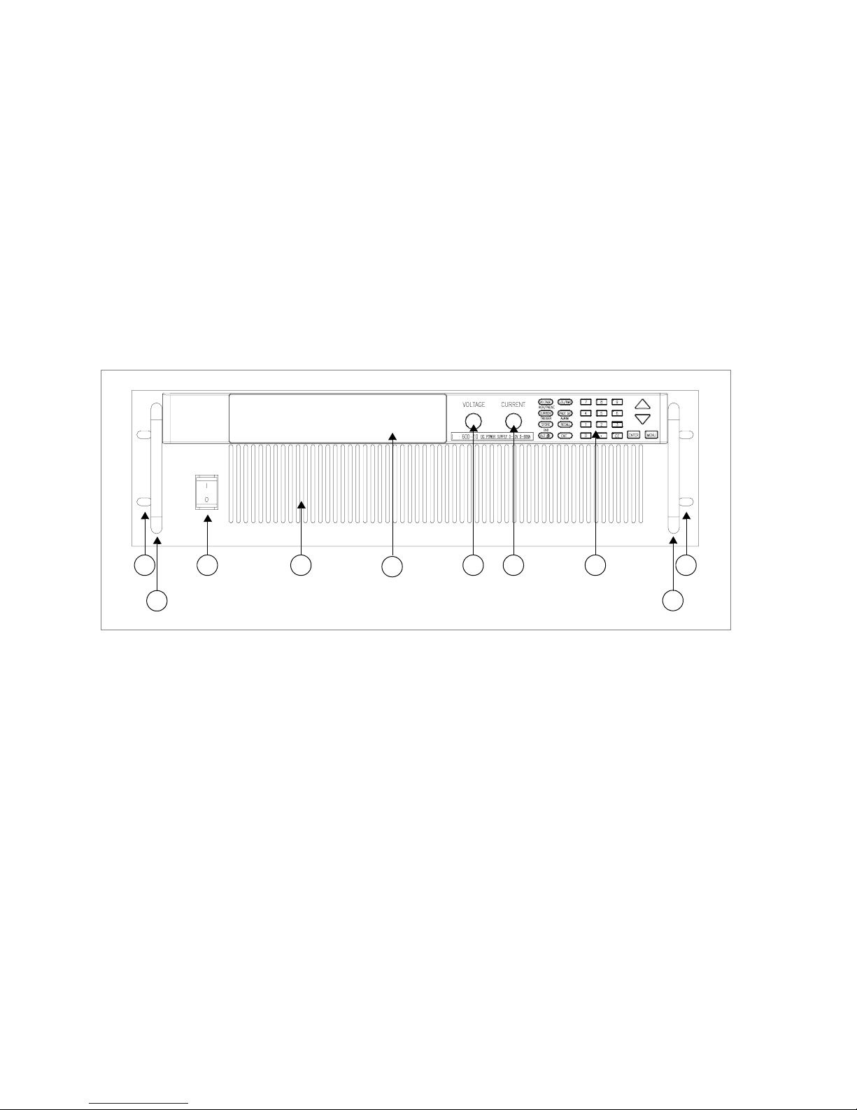
Figure 1.1 Front Panel (6000 Watt)
3 4
5
6 7 8 1
2
22 Operating Manual for XDC Series Power Supply
Artisan Technology Group - Quality Instrumentation ... Guaranteed | (888) 88-SOURCE | www.artisantg.com
Page 26
About The XDC Power Supply
Front Panel
1
3 4 5 6 7 8 1
2
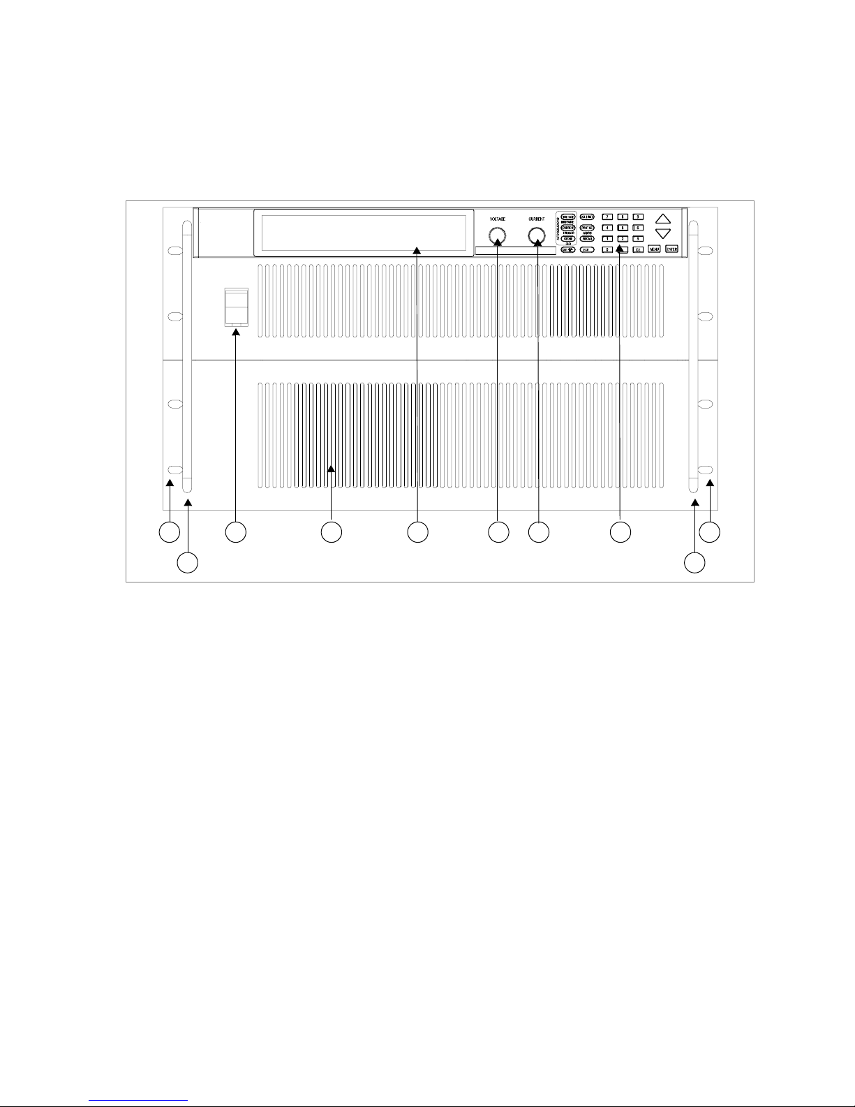
Figure 1.2 Front Panel (12000 Watt)
1. Rack mount brackets
2. Handles
3. On/Off switch
4. Air intake vents
5. Front panel display (vacuum fluorescent display). See Figure 1.4 for details.
6. Voltage knob
7. Current knob
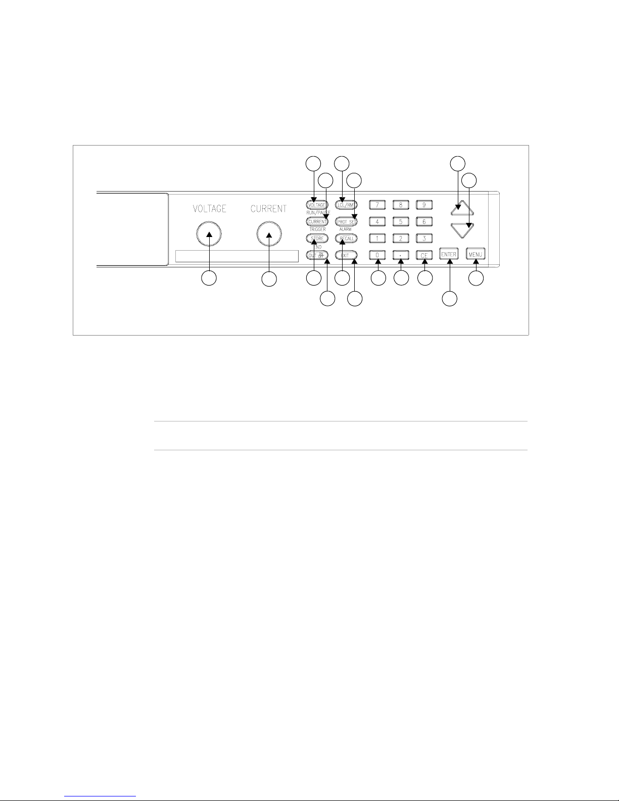
8. Keypad. (See Figure 1.3 for details.)
2
Release 3.0 23
Artisan Technology Group - Quality Instrumentation ... Guaranteed | (888) 88-SOURCE | www.artisantg.com
Page 27
About The XDC Power Supply
Front Panel
Figure 1.3 Keypad
1. Vo l tage k nob: Turn knob to increase or decrease output voltage. (This is a
velocity- sensitive rotary encoder.)
2. Current knob: Turn knob to increase or decrease output current limit. (This is
a velocity-sensitive rotary encoder.)
3
7
4
8
5
1
2
9
6
10
11
12
13
14
15
17
16
Note The secondary functions for keys 3 to 5 listed below operate when the power supply
is in Auto Sequence mode.
3. VOLTAGE set key: View and set voltage output setpoint.
RUN/PAUSE Auto Sequence Program: Start a selected program or pause the
program.
4. CURRENT set key: View and set current output setpoint.
TRIGGER for Auto Sequence Program: Apply a trigger when requested.
This key may also be used to advance to the next step in the program by pressing
and holding.
5. STORE settings key: Save power supply output settings to one of ten locations.
END Auto Sequence Programming: Stop the program. The program will start
from the beginning when RUN is pressed.
6. OUT ON/OFF key: Toggle between Output ON and Output OFF.
7. LCL/RMT key: Toggle between local mode and remote mode (or Go to Local
for GPIB operation) except during calibration.
24 Operating Manual for XDC Series Power Supply
Artisan Technology Group - Quality Instrumentation ... Guaranteed | (888) 88-SOURCE | www.artisantg.com
Page 28

About The XDC Power Supply
Front Panel
8. PROTECTION SET key: View and set protection setpoints.
ALARM response: Read and clear alarm messages. ALARM annunciator
indicates if there are any alarm messages.
9. RECALL settings key: Apply stored power supply settings.
10. EXIT key: Cancel operation, exit menu or get out of Calibration mode or Auto
Sequence mode. Automatic timeout will also cancel operation except calibration
and auto sequence operation.
11. Numeric keypad: Numbers 0 to 9, used for data entry.
12. Decimal key: Enter a decimal. Used for data entry.
13. CE key: Clear the entire data field. Used for data entry. In Store User Setting
mode, used to delete selected setting or program.
14. Up arrow key: Scroll through menus and lists, or, in data entry mode, increase
the displayed value. In default operating mode, use this key to view the output
power. In Auto Sequence Operating mode, use this key to view present sequence
number, step numbers, and sequence loop count.
15. Down arrow key: Scroll through menus and lists, or, in data entry mode,
decrease the displayed value.
16. ENTER key: Select a menu item or accept data.
17. MENU key: Access all menu functions.
Release 3.0 25
Artisan Technology Group - Quality Instrumentation ... Guaranteed | (888) 88-SOURCE | www.artisantg.com
Page 29

About The XDC Power Supply
Front Panel
Table 1 .1 Front Panel Functions
Key Functions
Voltage Setpoint Enter voltage
Current Setpoint Enter current
Output ON/OFF Toggle
Local/Remote Mode Toggle
Protection Set OVP level
UVP level
OCP level
UCP level
OPP level
UPP level
Fold Mode
Enter OV level
Enter UV level
Enter OC level
Enter UC level
Enter OP level
Enter UP level
Select fold mode
S/D if tripped?
S/D if tripped?
S/D if tripped?
S/D if tripped?
S/D if tripped?
Select fold delay
Read Alarms Read alarm msgs
Store User Setting Select 1 to 10
Recall Factory default
Last setting
User setting
Auto sequence
Select 1 to 10
Select 1 to 10
Auto Sequence Operation (Run/Pause, Trigger, Stop)
MENU Access menu functions
ENTER Make a selection
UP/DOWN Scroll to view selections, increment numerical entries
CE Clear entry
Numeric keypad Enter data
EXIT Cancel operation
Special Key Functions
UP View power readback (from default window)
CE Deletes a selected user setting from memory (Hold for 2 seconds)
EXIT Exit auto sequence
Select Y or N
Select Y or N
Select Y or N
Select Y or N
Select Y or N
26 Operating Manual for XDC Series Power Supply
Artisan Technology Group - Quality Instrumentation ... Guaranteed | (888) 88-SOURCE | www.artisantg.com
Page 30

Menu Function
ERROR MSGS Read error msgs
USER LINES Aux line A
Aux line B
PON CONFIG Factory default
Last setting
User setting
Auto sequence
S/D RECOVERY Select OTP
recovery
REMOTE
SELECT
REMOTE
CONFIG
AUTO SEQ PGM Select
CURRENT
SHARE
POWER
SETPOINT
DISPLAY
CONFIG
KNOB LOCKOUT Lock voltage knob? Lock current knob?
SETPOINT LIMIT Voltage limit
SLEW RATE Voltage slew Enter voltage step
CALIBRATION Calibrate voltage
Select remote interface
RS-232
GPIB
Analog
Multichannel
Sequence
No sharing
Master
Slave
Set power
Set display config
Current limit
Power limit
Voltage slew default
Calibrate current
Calibrate analog 5V voltage programming
Calibrate analog 5V voltage readback
Calibrate analog 5V current programming
Calibrate analog 5V current readback
Calibrate analog 10V voltage programming
Calibrate analog 10V voltage readback
Calibrate analog 10V current programming
Calibrate analog 10V current readback
Restore factory calibration
Change calibration security code
Configure aux line A
Configure aux line A
Set output on/off
Set output on/off
Select 1 to 10
Select 1 to 10
Select AC Off recovery
Select baud rate
Select address
Select input voltage range
Select address
Edit Sequence Select Step Edit Step Enter Value/Duration To Next Step
Set Repeat #Select repetitions for sequence
Trig Source Select trigger source
Delete Sequence Confirm delete
Display summed
current?
Enter max limit
Enter max limit
Enter max limit
Select flow control
Select PON SRQ
About The XDC Power Supply
Front Panel
Set aux line A polarity
Set aux line B polarity
Set output on/off
Set output on/off
Insert Step or EXIT to finish
Delete Step
Select Y or N
Enter min limit
Enter min limit
Enter min limit
Enter time interval
Release 3.0 27
Artisan Technology Group - Quality Instrumentation ... Guaranteed | (888) 88-SOURCE | www.artisantg.com
Page 31

About The XDC Power Supply
Display
MODEL INFO View info
Display
Figure 1.4 Front Panel Display
1. Main Display: Shows setpoints, readback, and menus. There are 14 characters.
Each character is 5 pixels wide by 7 pixels high.
2. Status Annunciators: See “Status Annunciators” on page 28 and Figure 1.5 for
detailed information.
3. Voltage, Current, and Power Bar Graphs: Show present voltage, current
limit, and power output in graphical format. Also indicates regulation mode.
Status Annunciators
1
3 5 7 11 13 15 17
2 4 6 8
1
2
9
10 12 14 16 18
19
20
3
21
22
Figure 1.5 Front Panel Display, Status Annunciators
28 Operating Manual for XDC Series Power Supply
Artisan Technology Group - Quality Instrumentation ... Guaranteed | (888) 88-SOURCE | www.artisantg.com
Page 32

About The XDC Power Supply
Status Annunciators
1. AUX A: Condition selected for auxiliary line A is TRUE.
2. Master: Power supply is selected to be the master in current share
configurations.
3. AUX B: Condition selected for auxiliary line B is TRUE.
4. Slave: Power supply is selected to act as a slave in current share configurations.
5. AUTO: Power supply is in auto sequence operation.
6. Pause: Auto sequence program is paused. (Output is still on.) Press
RUN/PAUSE key to continue.
7. SEQ: Power supply is in auto sequence setup mode (if Set is also turned on) or
in auto sequence operation.
8. Trigger?: Auto sequence program is waiting for a trigger signal to continue
execution.
9. ERR: An error has occurred.
10. Set: Setting or setpoint is to be entered.
11. ADR: Power supply is being addressed (receiving data). (All remote digital
interfaces.)
12. LCL: Power supply is under local (front panel) control.
13. SRQ: Service request. GPIB only.
14. RMT: Power supply is under remote control.
15. ALARM: Power supply is operating outside the parameters the user set by using
PROT SET, or the power supply’s internal temperature has exceeded an
internally set trip point (OTP).
16. OUT OFF: Power supply output is disabled; all other circuits are active; unit is
in standby mode.
17. OVP: Power supply has exceeded an over-voltage trip point.
18. Interlock: Signals that the external shutdown line (the safety interlock line) has
been activated, disabling the supply output.
19. OTP: Power supply has exceeded an over-temperature trip point, disabling the
supply output.
20. OUT ON: Output is on.
21. Bar graphs: Graphical representation of output voltage, current, and power.
22. CV, CC, CP: Power supply is in constant voltage mode, constant current mode,
or constant power mode.
Release 3.0 29
Artisan Technology Group - Quality Instrumentation ... Guaranteed | (888) 88-SOURCE | www.artisantg.com
Page 33

About The XDC Power Supply
Rear Panel
Rear Panel
2
1 3
Figure 1.6 Rear Panel (6000 Watt low and medium output shown)
1 1
4 5 6 7
1. Fan Exhaust Vents: Do not obstruct.
2. Remote Sensing Ports: From the rear point of view, left is negative; right is
positive.
3. DC Output: Bus bars are shown. Terminal blocks are used for higher voltages
(300 and 600 Vdc only).
4. Auxiliary Status Lines, External Interlock, and Trigger Input
86
9
1
1
10
5. Analog Program and Readback
6. CANbus Port: For current sharing or multichannel operation (optional for
6000 Watt units)
7. RS-232 Connector
8. GPIB (optional)
9. Protective Conductor Ground Screw
10. AC Input
11. Chassis ground stud
30 Operating Manual for XDC Series Power Supply
Artisan Technology Group - Quality Instrumentation ... Guaranteed | (888) 88-SOURCE | www.artisantg.com
Page 34

About The XDC Power Supply
Overview of Operation
Overview of Operation
Power ON Power ON describes the period between the time the AC power is turned ON and the
time the power supply is ready for normal operation. Each supply comes with a
series of factory default settings that may be in effect at the conclusion of the Power
ON period. These include:
• Output OFF: No current is sent to the DC output connections. You must press
Out ON/OFF to activate the supply output.
• Voltage 0V: The Voltage setpoint is zero.
• Current 0A: The Current setpoint is zero.
• Local mode operation
The output state depends on the Power ON output setting. You can customize the
Power ON settings to suit your needs. See “Configure Power ON Settings” on page
84 for more information.
Control
Modes
One local method and 4 remote methods are available for controlling the power
supply:
• Local Mode: Where the user operates the menu keypad and knobs
• RS-232: Where the user operates the supply remotely through a serial port
connection (standard feature).
• GPIB: Where the user operates the supply remotely through the faster General
Purpose Interface Bus. The GPIB bus follows the IEEE 488.2 standard and is an
optional feature of this power supply.
• Multichannel: Where the user operates the supply remotely through the
optional multichannel link between 2 or more (up to 50) power supplies
(optional feature).
• Analog: Where the user operates the supply remotely through the isolated
analog programming and readback port (standard feature). Three options are
available:
• Analog V and I
• Analog V
• Analog I
Each of these methods is referred to as a control mode.
Release 3.0 31
Artisan Technology Group - Quality Instrumentation ... Guaranteed | (888) 88-SOURCE | www.artisantg.com
Page 35

About The XDC Power Supply
Overview of Operation
32 Operating Manual for XDC Series Power Supply
Artisan Technology Group - Quality Instrumentation ... Guaranteed | (888) 88-SOURCE | www.artisantg.com
Page 36

Section 2. Installation
Overview
Section 2 provides recommendations and procedures for inspecting, installing, and
testing the power supply. For more information about controls and connectors, refer
to the front panel diagrams (Figure 1.1 to Figure 1.5) as well as the rear panel
diagram (Figure 1.6) in Section 1.
Basic Setup Procedure
Table 2.1 provides a summary of the setup procedure and an overview of the
subsections in this chapter. Use this table as a quick reference if you are familiar with
the installation requirements for the power supply. If you require more information,
each step in the table refers to a subsequent section which contains more details.
Complete each step in the sequence given.
Table 2.1 Basic Setup Procedure
Step # Description Action Reference
1 Inspection Visually inspect the power supply.
2 Installation Install the power supply, ensuring
adequate ventilation.
3 Input Power Connect AC input power. “AC Input Power” on page 40
4 Test Perform functional tests for voltage
mode operation, current mode
operation, and front panel controls.
5 Select Wires Select wires that can tolerate the DC
current output.
6 Connect Load Connect the load wires to the DC output. “Load Connections” on page 50
7 Connect Remote
Sensing (if required)
Connect remote sensing connectors on
power supply to load.
“Inspection, Cleaning, and
Packaging” on page 34
“Location, Mounting, and
Ventilation” on page 37
“Basic Checks or Self-Tests”
on page 45
“Load Wiring” on page 48
“Remote Sensing” on page 56
Release 3.0 33
Artisan Technology Group - Quality Instrumentation ... Guaranteed | (888) 88-SOURCE | www.artisantg.com
Page 37

Installation
Inspection, Cleaning, and Packaging
Inspection, Cleaning, and Packaging
Initial
Inspection
When you receive your power supply, do a quick visual check.
1. Ensure that the box contains the power supply, the operating manual, the AC
input cover and strain relief, and the output cover.
2. Inspect the unit for scratches and cracks as well as broken switches, connectors,
or displays.
If the unit is damaged, save all packaging materials and notify the carrier
immediately.
Maintenance Routine servicing of the power supply is not required except for periodic cleaning.
Whenever a unit is removed from operation, clean the metal surfaces with naphtha
or an equivalent mild solvent, and clean the front panel with a damp cloth using a
weak solution of soap and water. Use low-pressure compressed air to blow dust from
in and around vent openings and components on the printed circuit boards.
34 Operating Manual for XDC Series Power Supply
Artisan Technology Group - Quality Instrumentation ... Guaranteed | (888) 88-SOURCE | www.artisantg.com
Page 38

Returning Power Supplies to the Manufacturer
Installation
Returning Power Supplies to the Manufacturer
Return
Material
Authorization
Policy
Before returning a product directly to Xantrex you must obtain a Return Material
Authorization (RMA) number and the correct factory “Ship To” address. Products
must also be shipped prepaid. Product shipments will be refused and returned at your
expense if they are unauthorized, returned without an RMA number clearly marked
on the outside of the shipping box, if they are shipped collect, or if they are shipped
to the wrong location.
When you contact Xantrex to obtain service, please have your operating manual
ready for reference and be prepared to supply:
• The serial number of your product
• Information about the installation and use of the unit
• Information about the failure and/or reason for the return
• A copy of your dated proof of purchase
When you ship:
1. Package the unit safely following the procedures on page 36, preferably using
the original box and packing materials. Please ensure that your product is
shipped fully insured in the original packaging or equivalent. This warranty will
not apply where the product is damaged due to improper packaging.
2. Include the following:
• The RMA number supplied by Xantrex Technology Inc clearly marked on
the outside of the box.
• A return address where the unit can be shipped. Post office boxes are not
acceptable.
• A contact telephone number where you can be reached during work hours
• A brief description of the problem
Ship the unit prepaid to the address provided by your Xantrex customer service
representative.
If you are returning a product from outside of the USA or Canada:
In addition to the above, you MUST include return freight funds and are fully
responsible for all documents, duties, tariffs, and deposits.
If you are returning a product to a Xantrex Authorized Service Center (ASC):
A Xantrex return material authorization (RMA) number is not required. However,
you must contact the ASC prior to returning the product or presenting the unit to
verify any return procedures that may apply to that particular facility.
Release 3.0 35
Artisan Technology Group - Quality Instrumentation ... Guaranteed | (888) 88-SOURCE | www.artisantg.com
Page 39

Installation
Returning Power Supplies to the Manufacturer
Packaging for
Shipping or
Storage
Follow these instructions to prepare the power supply for shipping or storage.
1. When returning the unit or sending it to the service center, attach a tag to the unit
stating its model number (located on the front panel label) and serial number
(located on the rear panel label). Give the date of purchase and an invoice
number, if you have it, as well as a brief description of the problem.
2. For storage and shipping, repack the power supply in its original container. If the
original container is not available, seal the unit in a plastic bag and then pack it
into a wooden or sturdy cardboard box large enough to allow 2 in. (5cm) of
cushioning material to surround the unit. For cushioning, use material such as
foam slabs that are capable of supporting the unit.
3. Label the box as shown below in Figure 2.1.
4. If shipping, mark the service center address and your return address on the
carton.
5. If storing, stack no more than 5 boxes high. Check the storage temperature range
specification in Appendix E.
POWER SUPPLY
Model Number:
Serial Number:
___________________________
___________________________
FRAGILE – ELECTRONIC EQUIPMENT
Figure 2.1 Typical Box Label for Storage
36 Operating Manual for XDC Series Power Supply
Artisan Technology Group - Quality Instrumentation ... Guaranteed | (888) 88-SOURCE | www.artisantg.com
Page 40

Location, Mounting, and Ventilation
!
Use the power supply in rack-mounted applications only. The power supply is
designed to fit in a standard 19 in. (483mm) equipment rack.
Rack
Mounting
WARNING- High Energy and High Voltage
Ensure that the 8-32 rack mounting screws do not extend more than 1/8 in. (3.0mm)
into the sides of the power supply.
To install the power supply in an equipment rack:
1. Open the box containing the unit. See Figure 2.2.
2. With the help of at least one other person, lift the unit out of its package and slide
it into an empty space in a mounting rack equipped with rails that are rated to
support the unit’s weight. See Figure 2.3.
On 12000 Watt units, remove the temporary lifting handles before installing the
unit in a rack.
Installation
Location, Mounting, and Ventilation
CAUTION
The power supply is too heavy for one person to safely lift and mount. To avoid injury,
ask a co-worker for assistance.
3. While your assistant(s) holds the unit steady, fasten it to the rack by inserting
bolts through the mounting brackets on either side of the front panel and securing
them with a washer and nut.
4. The front panel mounting brackets are designed to prevent the unit from sliding
out of the rack, not to support its full weight. Provide adequate support for the
rear of the unit without obstructing the ventilation inlets. Use slide rails as
illustrated in Figure 2.3 or slide brackets attached to the 8-32 mounting holes on
each side of the unit. Follow the manufacturer’s instructions to install rails or
slides.
Release 3.0 37
Artisan Technology Group - Quality Instrumentation ... Guaranteed | (888) 88-SOURCE | www.artisantg.com
Page 41

Installation
Location, Mounting, and Ventilation
Figure 2.2 Unpacking the Power Supply (6000 Watt shown)
38 Operating Manual for XDC Series Power Supply
Artisan Technology Group - Quality Instrumentation ... Guaranteed | (888) 88-SOURCE | www.artisantg.com
Page 42
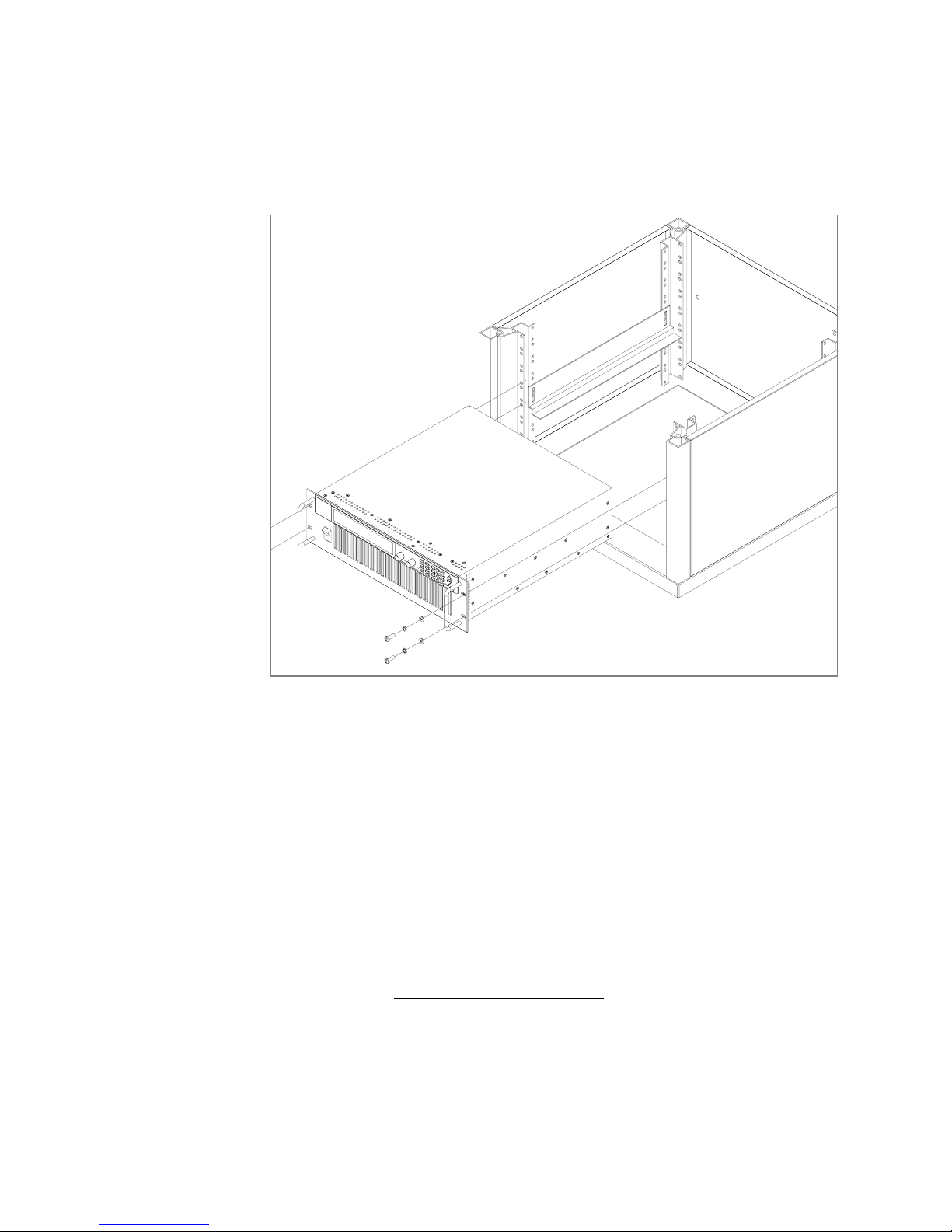
Installation
Location, Mounting, and Ventilation
Figure 2.3 Mounting the Power Supply in the Rack With Support Rails
1
(6000 W shown)
Ventilation Allow cooling air to reach the ventilation inlets on the front of the unit and allow 4 in.
(10 cm) of unrestricted air space at the rear of the unit for the fan exhaust. Ventilation
inlets are located on the top and sides; they are not required, however, and may be
blocked, if required.
See “Specifications and Characteristics” on page 227 for the operating ambient
temperature range.
1. Available from rack or cabinet vendors (e.g. Schroff, part number 30150-094).
Release 3.0 39
Artisan Technology Group - Quality Instrumentation ... Guaranteed | (888) 88-SOURCE | www.artisantg.com
Page 43

Installation
!
AC Input Power
AC Input Power
WARNING
Disconnect AC power from the unit before removing the connector cover. Live line
voltages may be exposed when the cover is removed.
WARNING
A safety ground wire must be connected to the unit as shown in Figure 2.4 and
Figure 2.6 to ensure operator safety.
CAUTION
When the power switch is turned on, output voltage or current previously set may be
applied to loads, depending on the supply configuration.
AC Input
Connector
The AC input connector is a standard wire clamp terminal block with 3-phase
connectors and a chassis ground connector. The safety ground wire, alternatively,
may be connected to the chassis using a ring tongue on the ground stud as shown in
Figure 2.4 and Figure 2.6.
Ground Connection
3-Phase Terminal Block Connectors
Figure 2.4 AC Input Connector for 6000 Watt units
40 Operating Manual for XDC Series Power Supply
Artisan Technology Group - Quality Instrumentation ... Guaranteed | (888) 88-SOURCE | www.artisantg.com
Page 44

Installation
AC Input Power
AC Input Wire The manufacturer recommends the AC input wire specified in Table 2.2 and
Table 2.3. This must be permanently connected to an approved AC distribution box
with suitably rated over-current protection. If you require a special cord, contact the
manufacturer.
Table 2.2 AC Wire Specification for 6000 Watt units
AC Input Voltage Range Wire
190–242Vac, 47–63Hz,
3-phase, 4 wire (standard)
342–500Vac, 47–63Hz,
3-phase, 4 wire (HV-Input)
Table 2.3 AC Wire Specification for 12000 Watt units
AC Input Voltage Range Wire
190–242Vac, 47–63Hz,
3-phase, 4 wire (standard)
342–500Vac, 47–63Hz,
3-phase, 4 wire (HV-Input)
4 x 10 AWG (3 wire plus safety ground), stranded
copper, 60
cable diameter, rated for 25A.
4 x 14 AWG (3 wire plus safety ground), stranded
copper, 60
cable diameter, rated for 13A.
4 x 6 AWG (3 wire plus safety ground), stranded
copper, 60
(OD) of cable is ≤ 1in., rated for 50 A.
4 x 10 AWG (3 wire plus safety ground), stranded
copper, 60
(OD) of cable is ≤ 1in., rated for 25 A.
°C minimum, 300V, 0.800 in. maximum
°C minimum, 600V, 0.800 in. maximum
°C minimum, 300V, outside diameter
°C minimum, 600V, outside diameter
AC Wire Input
See Figure 2.5, on page 42.
Connection
for 6000 W
To connect the 6000 W AC input wires:
1. Ensure that the AC input cord is de-energized, and that the power switch on the
front of the power supply is OFF.
2. Strip approximately 4 in. (10 cm) from the jacket of the AC wire. Strip 0.55 in.
(14 mm) at the end of each wire.
3. Undo the 2 screws for the AC wiring strain relief/cover on the rear panel.
Remove the cover.
4. Undo the strain relief screws. Insert the AC input cable through the strain relief
until the outer cable jacket is flush with the inside of the strain relief. Tighten the
strain relief cable clamp screws.
5. Insert the ground wire (green) 0.55 in. (14 mm) into the left-most terminal
location, and tighten securely. (The safety ground wire may alternatively be
connected to the chassis ground stud next to the terminal block, using a suitably
sized ring terminal).
Release 3.0 41
Artisan Technology Group - Quality Instrumentation ... Guaranteed | (888) 88-SOURCE | www.artisantg.com
Page 45
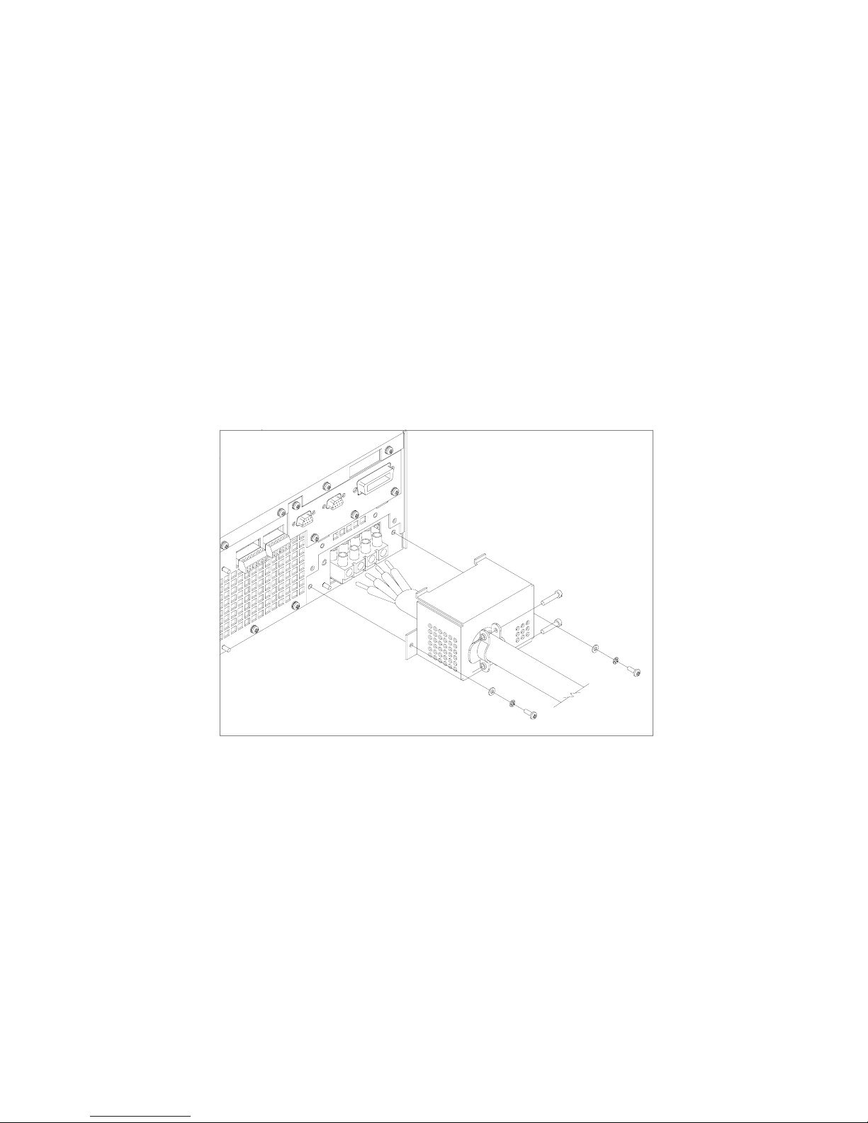
Installation
AC Input Power
6. Route the AC wires to the input terminal block by connecting the red, black, and
white wires to the remaining 3 cable clamp connectors. There is no set order for
connecting the wires. Any of the 3-phase wires can be connected to any of the 3
line input connectors. To connect each wire, loosen the terminal screw, insert the
stripped wire 0.55 in. (14mm) into the terminal, and tighten the screw securely.
7. Reinstall the AC input strain relief/cover, routing wires inside the cover to
prevent pinching.
8. Connect the free end of the cable to the AC source, checking that the voltage is
within the approved input range for the supply.
9. Energize the AC input.
It is now safe to turn the power supply on.
Figure 2.5 Attaching the AC Input Wires for 6000 Watt units
42 Operating Manual for XDC Series Power Supply
Artisan Technology Group - Quality Instrumentation ... Guaranteed | (888) 88-SOURCE | www.artisantg.com
Page 46

Installation
AC Input Power
AC Wire Input
Connection
for 12000 W
See Figure 2.6, on page 44.
To connect the 12000 W AC input wires:
1. Ensure that the AC input cord is de-energized, and that the power switch on the
front of the power supply is OFF.
2. Strip approximately 2.75 in. (70 mm) from the jacket of the AC wire. Strip
0.55 in. (14 mm) at the end of each wire.
3. Remove the square AC input cover plate from the AC input bracket on the rear
panel, and a round knock-out from either the rear or right side of the bracket.
4. Insert the AC input cable through the knock-out and through the removable nut
from the strain relief until there is enough cord to attach the AC wires to the
terminal block (the nut must be inside the AC input bracket). Tighten the cable
clamp screws and the strain relief nut inside the AC input bracket until the AC
input wire is firmly held between the nut and the cable clamp screws.
5. Insert the ground wire (green) 0.55 in. (14 mm) into the left-most terminal
location, and tighten securely.
6. Route the AC wires to the input terminal block by connecting the red, black, and
white wires to the remaining 3 cable clamp connectors. There is no set order for
connecting the wires. Any of the 3-phase wires can be connected to any of the 3
line input connectors. To connect each wire, loosen the terminal screw, insert the
stripped wire 0.55 in. (14mm) into the terminal, and tighten the screw securely.
7. Reinstall the AC input cover plate.
8. Connect the free end of the cable to the AC source, checking that the voltage is
within the approved input range for the supply.
9. Energize the AC input.
It is now safe to turn the power supply on.
Release 3.0 43
Artisan Technology Group - Quality Instrumentation ... Guaranteed | (888) 88-SOURCE | www.artisantg.com
Page 47

Installation
AC Input Power
left terminal:
Ground Connection
3 right terminals:
3-Phase Terminal Block Connectors
AC input cover plate
Figure 2.6 Attaching the AC Input Wires for 12000 Watt units
44 Operating Manual for XDC Series Power Supply
Artisan Technology Group - Quality Instrumentation ... Guaranteed | (888) 88-SOURCE | www.artisantg.com
Page 48

Basic Checks or Self-Tests
WARNING
The factory setting for Power ON is 0V and 0A with the output OFF. These settings
can be customized by end users. If you suspect that the power supply has been used
by someone else since it was received from the factory, be prepared for the unit to
power ON with a live DC output.
The functional test procedures described in this section include power-on and front
panel function checks as well as voltage and current mode operation checks.
Installation
Basic Checks or Self-Tests
Equipment
Required
• Digital Voltmeter (DVM) rated better than 0.05% accuracy.
• DC shunt 1mV/A (±0.25%) with connecting wire. The recommended current
ratings for the DC shunt and the wire must be at least 10% more than the output
current of the power supply.
Display Test To ensure that the display is working properly:
1. Turn the power switch ON.
2. Observe the display panel.
Every pixel should illuminate for 2 seconds as part of the power-on self-test.
If you need to rerun the test:
1. Turn the power switch OFF.
2. Wait until the pixels fade to black.
Some residual charge may remain in the capacitors after the power is OFF.
Waiting for the display to fade ensures that the capacitors have sufficiently
discharged their power to reset the power supply.
3. Turn the power switch ON.
4. Observe the display panel.
If you observe or suspect that one or more of the display pixels is malfunctioning,
contact the manufacturer.
Release 3.0 45
Artisan Technology Group - Quality Instrumentation ... Guaranteed | (888) 88-SOURCE | www.artisantg.com
Page 49

Installation
!
Basic Checks or Self-Tests
Power ON
Check
To complete the power on check:
1. Ensure that the AC power switch is OFF.
2. Connect the unit to an AC outlet.
3. Turn the front panel AC power switch to ON.
After a short power-on delay, the front panel digital meters and the CV annunciator
illuminate. Both voltmeter and ammeter displays should read zero.
Check the front panel annunciators. If OUT ON is illuminated, press OUT ON/OFF
to disable the output. The OUT OFF annunciator should now be illuminated. For an
illustration of the annunciators and their locations, see “Status Annunciators” on
page 28.
If the ERR indicator is lit, see “Read Error Messages” on page 82 or page 135 on
how to read an error message, and consult Appendix C to determine the meaning of
the error. If an unexpected error persists after the power has been cycled, contact the
manufacturer for assistance.
Voltage Mode Operation Check
WARNING
On units rated higher than 40V, ensure that the electrical connections are protected
to prevent accidental contact.
CAUTION
When making connections to the bus bars, ensure that each terminal’s mounting
hardware and wiring assembly are placed so they don’t touch the other terminal and
short the power supply outlet. Heavy connecting cables must have some form of
strain relief so the connections aren’t loosened and the bus bars aren’t bent.
To complete the voltage mode operation check:
1. Ensure that the OUT OFF annunciator is illuminated. If OUT ON is illuminated,
press OUT ON/OFF.
2. Connect a Digital Voltmeter (DVM) to the output terminals on the rear panel,
observing correct polarity.
3. Press OUT ON/OFF to turn the DC output ON.
46 Operating Manual for XDC Series Power Supply
Artisan Technology Group - Quality Instrumentation ... Guaranteed | (888) 88-SOURCE | www.artisantg.com
Page 50

Current Mode
Operation
Check
Installation
Basic Checks or Self-Tests
4. Slowly turn the Current knob clockwise 1 or 2 turns. Slowly turn the Voltage
knob clockwise and observe both the front panel voltmeter and the DVM. Do not
exceed 10V.
5. Compare the DVM reading with the front panel voltmeter reading to verify the
accuracy of the internal voltmeter. Both readings should be the same within the
accuracy of the meters. The minimum control range is from zero to the
maximum rated output for the power supply model. Check that the Constant
Voltage (CV) annunciator is illuminated.
6. Press OUT ON/OFF to turn the DC output OFF.
WARNING- High Temperature Hazard
Ensure that the current output does not exceed the rating of the shunt or load wiring
during this test.
To complete the current mode operation check:
1. Ensure that the OUT OFF annunciator is illuminated. If OUT ON is illuminated,
press OUT ON/OFF.
2. Connect the DC shunt across the output terminals on the rear panel.
3. Connect the DVM across the DC shunt.
4. Press OUT ON/OFF to turn the DC output ON.
5. Slowly turn the Voltage knob clockwise to a maximum reading of 10V.
6. Slowly turn the Current knob clockwise to a maximum reading of 10A.
7. Compare the DVM reading with the front panel ammeter reading using I=V/R
where I is the current, V is the DVM reading, and R is the DC shunt resistance.
The minimum control range is from zero to the maximum rated output for the
power supply model. Check that the Constant Current (CC) annunciator is
illuminated.
8. Press OUT ON/OFF to turn the DC output OFF.
9. Disconnect the DVM and the shunt.
Release 3.0 47
Artisan Technology Group - Quality Instrumentation ... Guaranteed | (888) 88-SOURCE | www.artisantg.com
Page 51

Installation
Load Wiring
Load Wiring
When connecting load wiring to the power supply, consider the following factors:
• Current carrying capacity of the wire
• Maximum load wiring length for operation with sense lines
• Noise and impedance effects of the load lines
Current
Carrying
Capacity
As a minimum, load wiring must have a constant capacity greater than the output
current rating of the power supply. This ensures that the wiring will not be damaged
even if the load is shorted. Table 2.4. shows the maximum current rating, based on
450A per square centimeter, for various gauges of wire rated for 105°C operation.
Operating at the maximum current rating results in a temperature rise of
approximately 30°C for a wire operating in free air. Where load wiring must operate
in areas with elevated ambient temperatures or bundled with other wiring, use larger
gauges or higher temperature-rated wiring. For high current applications,
custom-designed bus bars are typically used. To increase the current carrying
capability, use parallel cables.
Table 2.4 Current Carrying Capacity for Load Wiring
Wire Size
(AWG)
20 2.5 4 97
18 4 2 155
16 6 1 192
14 10 1/0 247
12 16 2/0 303
10 21 3/0 350
8 36 4/0 405
6 61 250MCM 455
Maximum Current (A)
Wire Size
(AWG)
1
Maximum Current
(A)
1. Single insulated conductors in free air, 30°C
48 Operating Manual for XDC Series Power Supply
Artisan Technology Group - Quality Instrumentation ... Guaranteed | (888) 88-SOURCE | www.artisantg.com
Page 52

Installation
Load Wiring
Load Wiring
Length for
Operation
with Sense
Lines
Noise and
Impedance
Effects
For applications using remote sensing, or for improved voltage regulation at the load,
you must limit the voltage drop across each load line. We recommend that you use
the larger load wiring to ensure a smaller voltage drop (1V maximum), although
units will compensate for up to 5V drop in each line with the remote sense lines
connected.
To minimize noise pickup or radiation, use the shortest possible length of
shielded-twisted pair wiring for load lines. Connect the shield to the chassis via a rear
panel mounting screw. Where shielding is not possible or is impractical, twisting the
wires together offers some noise immunity. When using local sense connections, use
the largest practical wire size to minimize the effects of load line impedance on the
regulation of the supply.
Release 3.0 49
Artisan Technology Group - Quality Instrumentation ... Guaranteed | (888) 88-SOURCE | www.artisantg.com
Page 53

Installation
!
Load Connections
Load Connections
WARNING
Exercise caution when operating the power supply. High energy levels can be stored
at the output terminals on a power supply in normal operation. In addition, potentially
lethal voltages exist in the power circuit and on the output and sense connectors of a
power supply with a rated output greater than 40V. Filter capacitors store potentially
dangerous energy for some time after power is removed.
CAUTION
When making connections to the bus bars, ensure that each terminal’s mounting
hardware and wiring assembly are placed to avoid touching the other terminal and
shorting the power supply outlet. Heavy connecting cables must have some form of
strain relief so they don’t loosen the connections or bend the bus bars.
Make load connections at the rear of the power supply at the positive and negative
output bus bars or to the 4-terminal wire clamp connector, depending on the model.
(See Figure 2.7.)
Wire Size The wire should be one size larger than necessary to accommodate the required
output current. Normally, the next largest commonly used gauge is used. For
example, use 10AWG for 20A, and 8AWG for 30A.
Isolation The wire must have a suitable insulating coating that will prevent arcing between the
positive and negative output current, and must be rated for 105
50 Operating Manual for XDC Series Power Supply
°C operation.
Artisan Technology Group - Quality Instrumentation ... Guaranteed | (888) 88-SOURCE | www.artisantg.com
Page 54

Load Connections
Single Load To connect a single load to the DC output bus bars (10–150V outputs):
1. Ensure that the power supply is powered OFF.
2. Place a bolt in the connecting hole of the negative bus bar, and fasten the
negative wire or bus bar, a washer, and a nut to the bolt.
3. Using a wrench, turn the bolt until it is secure at approximately 25 foot-pounds
(34Nm).
4. Fasten the positive wire or bus bar to the positive bus, using a bolt, washer, and
nut.
5. Tighten the bolt to approximately 25 foot-pounds (34Nm).
6. Ensure that the positive and negative wires are arranged so bare wires do not
come into contact with each other or the chassis.
To connect the DC output wire clamp connectors (300V, 600V outputs):
• Connect appropriately sized wires as described in steps 1 to 6 above, except strip
0.5 in. (14mm) of insulation off each load wire, and clamp in the output
connector by securely tightening the vertical clamp screw for each output.
Installation
Release 3.0 51
Artisan Technology Group - Quality Instrumentation ... Guaranteed | (888) 88-SOURCE | www.artisantg.com
Page 55
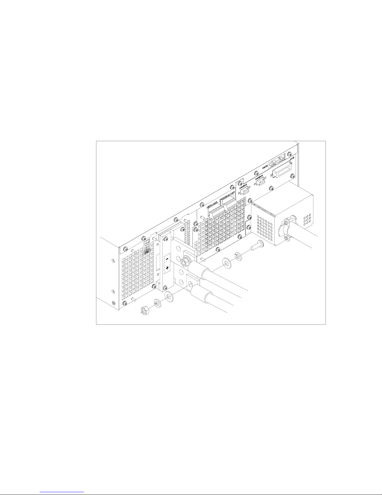
Installation
Load Connections
Multiple
Loads
To connect multiple loads in parallel:
• Follow the “Single Load” procedure with the following exception:
• To minimize interaction between loads, bring the wiring for each load directly
back to the supply output. When each load to the power supply is wired
separately, the loads will see only the precisely regulated output from the supply.
If 2 loads share a single cable, the fluctuation in current to one load will cause
the voltage to vary on the others. This is due to wire impedance drops.
Figure 2.7 Fastening the Output Wires (6000 Watt)
52 Operating Manual for XDC Series Power Supply
Artisan Technology Group - Quality Instrumentation ... Guaranteed | (888) 88-SOURCE | www.artisantg.com
(Low and Medium Voltage)
Page 56
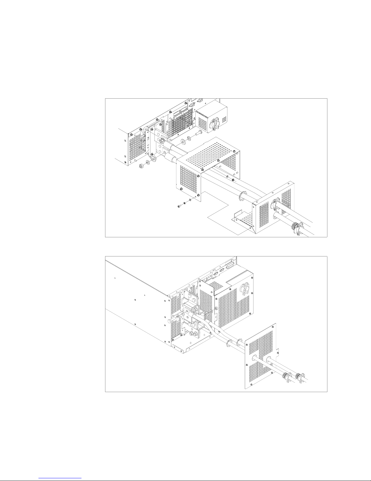
Installation
Load Connections
Output Strain
Relief/Cover
See Figure 2.8 and Figure 2.9 for installation of the output cover. Use this cover to
protect users from accidental contact with the bus bars and to clamp output cables in
place.
Figure 2.8 Output Bus Bar Cover for 6000 Watt units
(Low and Medium Voltage)
Figure 2.9 Output for 12000 Watt units (Low and Medium Voltage)
Release 3.0 53
Artisan Technology Group - Quality Instrumentation ... Guaranteed | (888) 88-SOURCE | www.artisantg.com
Page 57
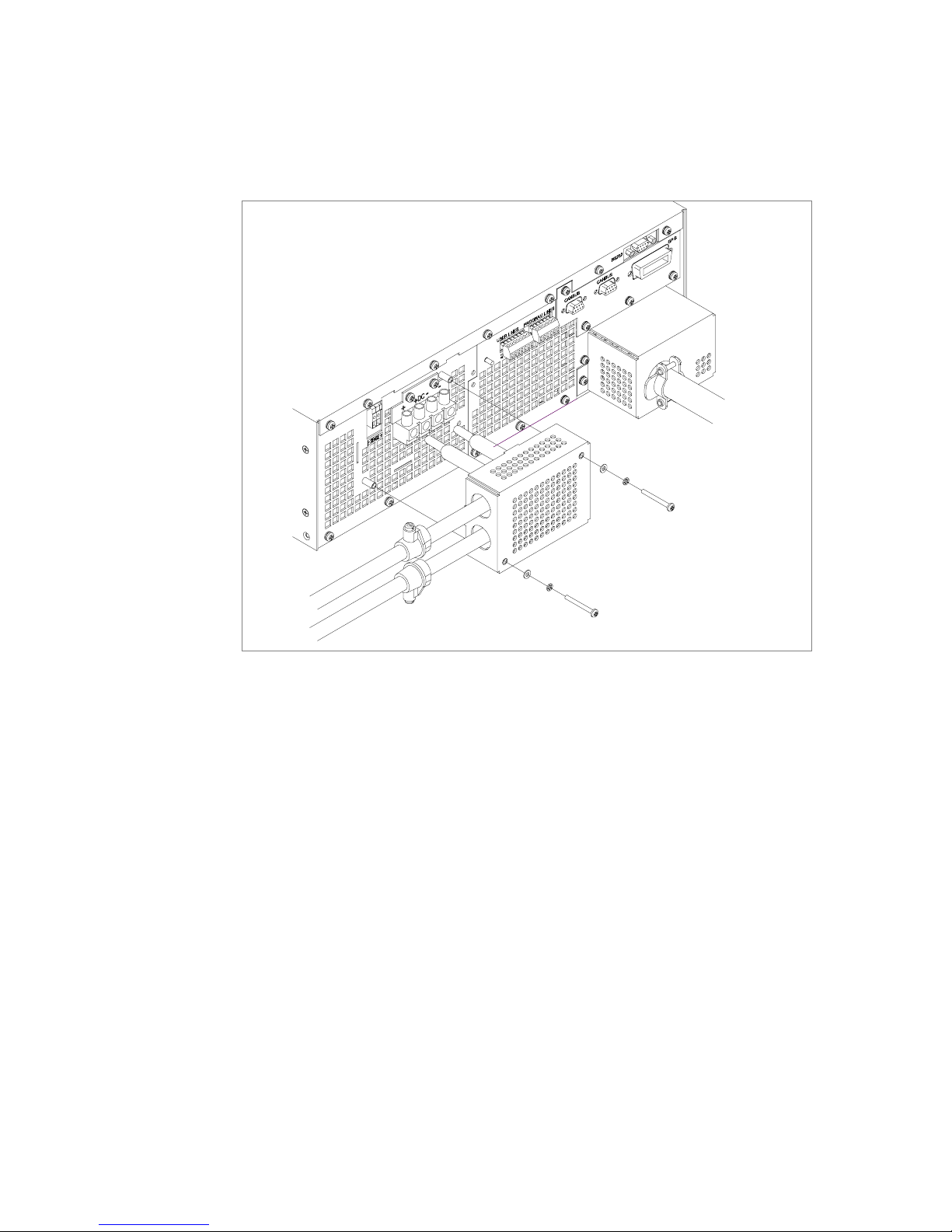
Installation
Load Connections
Figure 2.10Output Cover with Strain Relief for 6000 Watt units
(High Voltage 300–600V)
54 Operating Manual for XDC Series Power Supply
Artisan Technology Group - Quality Instrumentation ... Guaranteed | (888) 88-SOURCE | www.artisantg.com
Page 58

Installation
Load Connections
Figure 2.11Output for 12000 Watt units (High Voltage 300–600V)
Release 3.0 55
Artisan Technology Group - Quality Instrumentation ... Guaranteed | (888) 88-SOURCE | www.artisantg.com
Page 59

Installation
Remote Sensing
Remote Sensing
The power supply regulates the output voltage at the output connectors in its normal
configuration without remote sense lines connected.
Remote sensing lets the power supply track and regulate the output voltage at the
load, and thereby compensate for the voltage drop in the load lines. The power
supply will only compensate within the limitations of its voltage rating, to a
maximum of 5V per load line. Remote sensing is normally only required for critical
loads which cannot tolerate the slight voltage drop in the load lines caused by their
resistance. Remote sensing has no effect when the power supply is operating in
Constant Current mode.
Two remote sensing connectors are located on the rear panel of the power supply.
See “Rear Panel” on page 30 for location and polarity. Connect 2 wires from these
ports to the load, where the power supply cables terminate for your connection.
Carefully observe the correct polarity when making the connection. On 12000 Watt
units, connect the sense wires to the connector on the top or master power module.
The remote sensing input is sensitive to electrical noise, so always use a shielded
twisted pair, 22AWG or greater for the sense line cable. Terminate the shield to the
supply chassis or the negative output of the power supply for best results.
56 Operating Manual for XDC Series Power Supply
Artisan Technology Group - Quality Instrumentation ... Guaranteed | (888) 88-SOURCE | www.artisantg.com
Page 60

Section 3. Operation
Overview
Once you have installed the power supply and connected both the AC input power
and the load as explained in Section 2, the power supply is in its default
configuration and is ready to operate in local control mode.
Section 3 begins by explaining how to power on and power off the power supply. It
then provides information about configuring the power supply, and also gives
procedures for operating the supply via the front panel controls and menu functions.
In addition, brief descriptions are provided of Constant Voltage, Constant Current,
and Constant Power modes. See “Power Supply Operation” on page 64.
Powering ON
the Power
Supply
WARNING- Shock Hazard
The factory setting for Power ON is 0V and 0A with the output OFF. These settings
can be customized by end users. If you suspect that the power supply has been used
by someone else since it was received from the factory, be prepared for the unit to
power ON with a live DC output.
To power on the power supply:
1. Ensure that the AC power switch is OFF.
2. Connect the unit to an AC outlet.
3. Turn on the front panel AC power switch.
After a short power-on delay, the digital meters on the front panel and the CV
annunciator illuminate. The voltmeter and ammeter displays should read zero.
Check the front panel annunciators. If OUT ON is illuminated, press OUT ON/OFF
to disable it. The OUT OFF annunciator should now be illuminated. For an
illustration of the annunciators and their locations, see Figure 1.5.
Release 3.0 57
Artisan Technology Group - Quality Instrumentation ... Guaranteed | (888) 88-SOURCE | www.artisantg.com
Page 61

Operation
Power Supply Operating States
Powering
OFF the
Power Supply
From the front panel, the safest method for shutting down the power supply is:
Step # Do This You Will See
OUT
ON
OFF
illuminates; Ouput V and I are 0.
fades to black.
1 The OUT OFF annunciator
2 Switch the AC power to OFF. The AC OFF alarm, and then the unit
Power Supply Operating States
The power supply has 5 operating states:
• Power-On
• Output Shutdown
• Soft Start
• Normal Operation
• Calibration
Power-On This is the period between the time that AC power is applied to the supply (AC
breaker turned on) and the time that the power supply is ready for operation. During
this period, the internal circuits are powering up and performing self-tests. At the end
of the Power-On period, the supply is normally in its default Power-On mode with
the output OFF, V
SET
=0 and I
SET
=0.
Output
Shutdown
In this state, the output is disabled and there is no output regardless of power settings.
The power supply can be placed in the Output Shutdown state by a command (via
the front panel or from the programming interface), via the Interlock signal, or from
a protection mechanism. This is also called the Standby mode.
Soft Start In this state, the output power is ramping up gradually towards its target load. This
reduces equipment stress. This state occurs whenever the supply output is set to ON
or a protection state is re-set, and is approximately 2 seconds in duration.
Normal
Operation
This is the normal operating state for the power supply. The power supply is ready
to accept commands.
Calibration This is a service mode that is used to calibrate setpoints and readback levels for
accuracy. Calibration should only be performed by qualified service personnel. For
detailed information, see Appendix A.
58 Operating Manual for XDC Series Power Supply
Artisan Technology Group - Quality Instrumentation ... Guaranteed | (888) 88-SOURCE | www.artisantg.com
Page 62

Power Supply Regulation Modes
The power supply has 3 regulation modes while in the Normal Operation State:
• Constant Voltage (CV)
• Constant Current (CC)
• Constant Power (CP)
The CV, CC, and CP annunciators indicate the regulation mode.
Operation
Power Supply Regulation Modes
Constant
Voltage (CV)
Constant
Current (CC)
Constant
Power (CP)
In this mode, the supply’s output voltage is constant while the current and power
vary with the load. The power supply will operate in constant voltage mode
whenever the load current I
(I
L=VSET/RL
). In constant voltage mode, the power supply maintains the output
is less than the current limit setting I
L
voltage at the selected value (V
) while the load current IL varies with the load
SET
, or: IL<I
SET
SET
.
requirements.
In this mode, the supply’s output current is constant while the voltage and power
vary with the load. The power supply will operate in constant current mode
whenever the load resistance is low enough that the load current I
current limit setting I
maintains the output current at the selected value (I
SET
. (VL=I
). In constant current mode, the power supply
SETRL
) while the load voltage VL
SET
is equal to the
L
varies with the load requirements.
In this mode, the supply’s output power is constant while the voltage and current
vary with the load resistance. The power supply will operate in Constant Power
mode when the power drawn by the load is equal to the power setpoint and the
product of the voltage and current setpoint (V
limit point (P
power at the selected value (P
). In Constant Power mode, the power supply maintains the output
SET
) while the load voltage VL and load current IL
SET
SET
and I
) is greater than the power
SET
varies with the load requirements. The power limit is normally set to the maximum
supply rating, so the Constant Voltage or Constant Current modes will always be in
effect without entering into the Constant Power mode of operation.
Automatic
Mode
Crossover
This feature allows the power supply to automatically switch operating modes in
response to changing load requirements. If, for example, the power supply was
operating in Constant Voltage (CV) Mode (I
load current (I
supply would automatically switch into Constant Current (CC) Mode and the output
voltage would vary in response to changes in load current. If the additional load was
subsequently removed so the load current was again LESS THAN the current limit
setting, the supply would automatically return to Constant Voltage (CV) Mode.
Release 3.0 59
Artisan Technology Group - Quality Instrumentation ... Guaranteed | (888) 88-SOURCE | www.artisantg.com
< I
L
) became EQUAL TO the current limit setting (I
L
), and the load changed so the
SET
), the power
SET
Page 63

Operation
Remote Control Modes
Remote Control Modes
A number of control interfaces are available. You can control the power supply
remotely using 0–5V or 0–10V signals via the remote analog programming interface
or from a remote terminal using a remote digital interface. A remote digital interface
following RS-232 protocol is standard. An optional remote digital interface
following IEEE 488.2 (GPIB) protocol is also available. An optional CANbus port
for 6000 Watt units is also available which enables multi-channel communication
from a single GPIB address, and supports current sharing with parallel connected
units. (For detailed information, see Section 4, “Remote Operation”.)
60 Operating Manual for XDC Series Power Supply
Artisan Technology Group - Quality Instrumentation ... Guaranteed | (888) 88-SOURCE | www.artisantg.com
Page 64

Front Panel Controls
The power supply is shipped ready to operate in local mode. The factory default
power-on setting is 0V, 0A with the DC output turned off.
This section describes the function keys, menu options, and control knobs that you
use to operate the power supply. (Additional details about the front panel keys,
control knobs, and display annunciators are provided in Section 1, “About The XDC
Power Supply”.)
The next section (“Power Supply Operation” on page 64) provides details about
configuring and operating the power supply.
Operation
Front Panel Controls
Function
Keys
Eight function keys are located on the front panel. Each is described below. For the
purposes of simple front panel control, you should understand the function of the
LCL/RMT, OUT ON/OFF, VOLTAGE, and CURRENT keys.
1. VOLTAGE: Lets you pre-set a setpoint before enabling it. To pre-set a voltage
setpoint, press VOLTAGE, use the Voltage knob or the numeric keypad to enter
a value, and then press ENTER to enable it. (See “Set Voltage” on page 64.)
This output can be changed while the output is OFF.
2. CURRENT: Lets you pre-set a setpoint before enabling it. To pre-set a current
setpoint, press CURRENT, use the Current knob or the numeric keypad to enter
a value, and then press ENTER to enable it. (See “Set Current” on page 64.)
This output can be changed while the output is OFF.
3. STORE: Lets you save power supply settings. (See “Store User Settings” on
page 77.)
4. OUT ON/OFF: This is a toggle key that enables and disables the power supply
output. Normally, you should leave the power supply in its Output Off state
when no load is attached or there is no need for DC output. (See “Turn Output
On or Off” on page 65.)
When the Out On annunciator is illuminated, the output is on. When the Out Off
annunciator is illuminated, the output is off.
5. LCL/RMT: This key lets you toggle between local and remote control. If the
RMT annunciator is illuminated, press LCL/RMT to return control to the front
panel, if local mode has been enabled by the controller. (See “Toggle
Local/Remote” on page 74.)
Release 3.0 61
Artisan Technology Group - Quality Instrumentation ... Guaranteed | (888) 88-SOURCE | www.artisantg.com
Page 65

Operation
Front Panel Controls
6. PROT SET: Lets you view and set protection setpoints. (See “Set Output
Protection” on page 65.)
7. RECALL: Lets you apply stored power supply settings. (See “Recall Settings”
on page 79.)
8. EXIT: Lets you cancel an operation or leave Calibration mode or Auto
Sequence mode.
Menu
Navigation
Top Level
Menu Items
Four keys allow you to access many functions available on the menu. These keys are
MENU, ENTER, and the Up and Down arrow keys.
To display the first menu item, press MENU. To display the other top level menu
items in the order listed below, press MENU or the Down arrow repeatedly. To
display the other items in reverse order, press the Up arrow repeatedly.
The top level menu items are:
1. ERROR MSGS: Lists up to 50 queued errors. (See “Read Error Messages” on
page 82.)
2. USER LINES: Configures auxiliary lines A and B. (See “Configure User
Lines” on page 83.)
3. PON CONFIG: Configures the power-on settings. (See “Configure Power ON
Settings” on page 84.)
4. S/D RECOVERY: Sets up shutdown recovery options for AC Off and
Over-Temperature Protection. (See “Set Shutdown Recovery for AC Off and
OTP” on page 71.)
5. REMOTE SELECT: Sets up the remote access option. (See “Select Remote
Control Source” on page 75.)
6. REMOTE CONFIG: Configures the remote access option. (See “Configure
Remote Control Source” on page 76.)
7. AUTO SEQ PGM: Programs automatic sequences. (See “Program Auto
Sequence” on page 87.)
8. CURRENT SHARE: Sets up master/slave relationships for multiple-supply
configurations. (See Section 5, “Current Sharing (6000 Watt only)”.)
9. POWER SETPT: Sets up the power output. (See “Set Power” on page 65.)
10. DISPLAY CFG: Sets up the display to show the desired combination of
voltage, current, and power. (See “Configure Display” on page 98.)
62 Operating Manual for XDC Series Power Supply
Artisan Technology Group - Quality Instrumentation ... Guaranteed | (888) 88-SOURCE | www.artisantg.com
Page 66

Operation
Front Panel Controls
11. KNOB LOCKOUT: Locks out either the Voltage or Current knob, or locks out
both. (See “Lock Out Control Knobs” on page 98.)
12. SETPT LIMIT: Sets up minimum and maximum voltage, current, and power
setpoints. (See “Set V, I, and P Limits” on page 100.)
13. SLEW RATE: Sets the programmable slew rate. (See “Slew Rate” on page
102.)
14. CALIBRATION: Displays the Calibration menu. This menu item can be
password protected. (See Appendix , “.”.)
15. MODEL INFO: Displays make, electrical ratings, ROM version, FPGA
version, and SCPI version. (See “View Model Information” on page 104.)
Control
Knobs
The Voltage and Current knobs are the simplest way to control the power supply.
The Voltage and Current knobs are digital encoders, and therefore, there are no start
or end points to their rotation, and their rotation positions are meaningless when the
power supply is powered OFF. The control knobs can be disabled through a menu
command. See “Lock Out Control Knobs” on page 98 for more information.
Release 3.0 63
Artisan Technology Group - Quality Instrumentation ... Guaranteed | (888) 88-SOURCE | www.artisantg.com
Page 67

Operation
Power Supply Operation
Power Supply Operation
This section describes how to configure and operate the power supply.
Set Voltage The VOLTAGE key allows you to set and view the DC voltage output setpoint.
Step # Do This You Will See
VOLTAGE
1 Set #####V
Use the numeric keypad, Voltage
2
knob, or arrow keys to enter a value
(0–103% of rated voltage).
3 This saves the setting and enables
ENTER
the new voltage setpoint.
Set Current The CURRENT key allows you to set and view the DC current output setpoint.
Step # Do This You Will See
CURRENT
1 Set #####A
Use the numeric keypad, Current
2
knob, or arrow keys to enter a value
(0–103% of rated current).
3 This saves the setting and enables
ENTER
the new current setpoint.
64 Operating Manual for XDC Series Power Supply
Artisan Technology Group - Quality Instrumentation ... Guaranteed | (888) 88-SOURCE | www.artisantg.com
Page 68

Operation
Power Supply Operation
Set Power The POWER SETPOINT menu option lets you select the power output limit,
measured in watts. The following table shows how to access and work with the
Power Setpoint option. The power setpoint is normally at the maximum rating of the
power supply, in the factory default configuration and does not need to be re-set for
typical use.
Step # Do This You Will See
Turn Output
On or Off
Set Output
Protection
1 ERROR MSGS
2
3 SET ##### W
4
5 This saves the value and enables the
MENU
Press 8 times.
ENTER
Use the numeric keypad or arrow
keys to enter the value, which must
be 3–103% of the unit’s rated power.
ENTER
POWER SETPOINT
new power setpoint.
Use the OUT ON/OFF toggle key to enable or disable the power supply’s output.
When the output is disabled, the voltage and current at the output are zero regardless
of the setpoints.
When the output is on and you press OUT ON/OFF, OUTPUT OFF is momentarily
displayed. Then the readback is 0000V 0000A to indicate that output is zero, and
the OUT OFF annunciator illuminates. This is also known as Standby mode.
When you press OUT ON/OFF again, the OUT ON annunciator illuminates and the
power supply resumes normal operation, with the display showing a readback of the
output.
Seven configurable protection mechanisms are available:
• OVP: Over-Voltage Protection. Factory default = 103% V
RATED
• UVP: Under-Voltage Protection. Factory default = 0V (disabled)
• OCP: Over-Current Protection. Factory default = 0A (disabled)
• UCP: Under-Current Protection. Factory default = 0A (disabled)
• OPP: Over-Power Protection. Factory default = 0W (disabled)
• UPP: Under-Power Protection. Factory default = 0W (disabled)
• Fold: Fold Protection. (See below.)
Release 3.0 65
Artisan Technology Group - Quality Instrumentation ... Guaranteed | (888) 88-SOURCE | www.artisantg.com
Page 69

Operation
Power Supply Operation
OVP shuts down the power supply if the protection limit is exceeded. The other
options offer a choice: they shut down the power supply or issue a warning. When
the protection level is set to zero, that mechanism is considered disabled. However,
in the case of OVP, a hardware protection mechanism still exists.
The last protection mechanism is Fold Mode protection, when the unit will shut
down if it enters the selected regulation mode for a specified period of time.
Other protection mechanisms designed to protect the power supply are:
• AC Off: AC Off protection will disable the output if the AC line drops below
• High Temperature Alarm: A High Temperature condition will queue an alarm
• Over Temperature Protection (OTP): An over temperature condition will
• Sense Protection: Sense Protection will disable the output when the internal
the acceptable range.
message when the temperature of critical internal components nears the
maximum operating temperature.
disable the output.
sense circuit is tripped by either reversed polarity at the output of the supply or
a high voltage present at the output.
Recovery options are available for AC Off and OTP.
Also, see “Status Registers” on page 142.
66 Operating Manual for XDC Series Power Supply
Artisan Technology Group - Quality Instrumentation ... Guaranteed | (888) 88-SOURCE | www.artisantg.com
Page 70

To set the Over-Voltage Protection:
Step # Do This You Will See
PROT SET
1 OVP SHUTDOWN
ALARMS
Operation
Power Supply Operation
2 OVP SET 0V
3
ENTER
Use the Voltage knob, the numeric,
keypad, or the arrow keys to enter a
OVP SET ####V
value. The value must be between
0–103% of the unit’s rated voltage.
4 This setting is saved and the display
ENTER
returns to its default operating mode.
The other protection options follow a similar procedure, but have 2 extra steps:
1. When you press PROT SET / ALARMS, the OVP prompt appears. Press
PROT SET/ ALARMS repeatedly to cycle through the other protection
options.
2. Protection options, other than OVP, prompt you with S/D if trip? N
Use the arrow keys to select Ye s or No.
Ye s shuts down the power supply if the protection limit is reached.
No issues a warning (a message in the Alarms menu) without shutting down the
supply.
Release 3.0 67
Artisan Technology Group - Quality Instrumentation ... Guaranteed | (888) 88-SOURCE | www.artisantg.com
Page 71

Operation
Power Supply Operation
These 2 extra steps are shown in the following example.
To set the Under-Voltage Protection:
Step # Do This You Will See
PROT SET
1 OVP SET 0V
ALARMS
2 Press repeatedly until the
PROT SET
ALARMS
3 UVP SET 0V
Use the Voltage knob, the numeric
4
keypad, or the arrow keys to enter a
desired setting appears.
ENTER
UVP SET 0V
UVP SET ####V
value (0–103% of the unit’s rated
voltage).
5 S/D if trip? N
6 Use the arrow keys to select Yes or
ENTER
S/D if trip? Y
No. For this example, Yes is selected.
7 This setting is saved and the display
ENTER
returns to its default operating mode.
To set the Over-Current Protection:
Step # Do This You Will See
PROT SET
1 OVP SET 0V
2 Press repeatedly until the
ALARMS
PROT SET
ALARMS
OCP SET 0A
desired setting appears.
3 OCP SET 0A
4
ENTER
Use the Current knob, the numeric
keypad, or the arrow keys to enter a
value (0–103% of the unit’s rated
current).
5 S/D if trip? N
ENTER
6 Use the arrow keys to select Yes or
No. For this example, Yes is selected.
7 This setting is saved and the display
ENTER
68 Operating Manual for XDC Series Power Supply
Artisan Technology Group - Quality Instrumentation ... Guaranteed | (888) 88-SOURCE | www.artisantg.com
OCP SET ####A
S/D if trip? Y
returns to its default operating mode.
Page 72

To set the Under-Current Protection:
Step # Do This You Will See
PROT SET
1 OVP SET 0V
2 Press repeatedly until the
ALARMS
PROT SET
ALARMS
UCP SET 0A
desired setting appears.
Operation
Power Supply Operation
3 UCP SET 0A
4
ENTER
Use the Current knob, the numeric
keypad, or the arrow keys to enter a
UCP SET ####A
value. The value must be between
0–103% of the unit’s rated current.
5 S/D if trip? N
6
7 This setting is saved and the display
ENTER
Use the arrow keys to select Yes or No.
For this example, Yes is selected.
ENTER
S/D if trip? Y
returns to its default operating mode.
To set the Over-Power Protection:
Step # Do This You Will See
PROT SET
1 OVP SET 0V
2 Press repeatedly until the
3 OPP SET 0W
4
ALARMS
PROT SET
ALARMS
desired setting appears.
ENTER
Use both the Current and Voltage
knobs, or the numeric keypad, or the
arrow keys to enter a value. The
value must be between 0W and
103% of the unit’s rated power.
OPP SET 0W
OPP SET ####W
5 S/D if trip? N
6 Use the arrow keys to select Yes or
7 This setting is saved and the display
Release 3.0 69
Artisan Technology Group - Quality Instrumentation ... Guaranteed | (888) 88-SOURCE | www.artisantg.com
ENTER
S/D if trip? Y
No. For this example, Yes is selected.
ENTER
returns to its default operating mode.
Page 73

Operation
Power Supply Operation
To set the Under-Power Protection:
Step # Do This You Will See
PROT SET
1 OVP SET 0V
ALARMS
2 Press repeatedly until the
PROT SET
ALARMS
3 UPP SET 0W
Use both the Current and Voltage
4
knobs, or the numeric keypad, or the
desired setting appears.
ENTER
UPP SET 0W
UPP SET ####W
arrow keys to enter a value (must be
between 0W and 103% of the unit’s
rated power).
5 S/D if trip? N
6
7 This setting is saved and the display
ENTER
Use the arrow keys to select Yes or
No. For this example, Yes is selected.
ENTER
S/D if trip? Y
returns to its default operating mode.
Fold Protection options are:
• None: Fold protection disabled
• CC: Shutdown on entering CC mode
• CV: Shutdown on entering CV mode
• CP: Shutdown on entering CP mode
A programmable delay time causes the supply to wait before shutting down the
output.
70 Operating Manual for XDC Series Power Supply
Artisan Technology Group - Quality Instrumentation ... Guaranteed | (888) 88-SOURCE | www.artisantg.com
Page 74

To set Fold Protection:
Step # Do This You Will See
PROT SET
1 OVP SET 0V
2 Press repeatedly. Fold SD Mode
ALARMS
PROT SET
ALARMS
Operation
Power Supply Operation
Set
Shutdown
Recovery for
AC Off and
OTP
3
4
ENTER
Use the arrow keys or the numeric
keypad to select the value: None, CC,
Fold on ####
CV, CP
5
6
7 This setting is saved.
ENTER
Use the arrow keys or the numeric
keypad to select the delay time.
ENTER
Delay 0s
The Shutdown Recovery menu offers 2 options for AC Off (ACO) and
Over-Temperature protection (OTP):
• Auto-Recovery: With this method, the power supply returns to its normal
operating state once the alarm condition no longer exists. For example, if there
was an over-temperature alarm and the protection was set to auto-recovery, the
power supply would return to its normal operating state once the temperature
was reduced below the alarm level.
• Latched: With this method, the power supply remains in Shutdown state until
the operator manually clears the protection level and manually turns the output
back on.
You can set either or both the OTP and AC Off to Auto-Recovery or Latched.
Release 3.0 71
Artisan Technology Group - Quality Instrumentation ... Guaranteed | (888) 88-SOURCE | www.artisantg.com
Page 75

Operation
Power Supply Operation
To set both OTP and AC Off to Auto-Recovery:
Step # Do This You Will See
Respond to
Alarms
1 ERROR MSGS
2 3 times
3 OTP Latched
4 OTP AutoRecov
5 ACO AutoRecov
6
1. You can also press MENU 4 times to bring up the Shutdown Recovery option.
2. The default is Latched. You can leave it at Latched or change it to Auto-Recovery. Press
either arrow key repeatedly until the desired option appears.
3. The default is AutoRecov. You can leave it at Auto-Recovery or change it to Latched. Press
either arrow key repeatedly until the desired option appears.
MENU
ENTER
ENTER
ENTER
1
S/D RECOVERY
2
3
OTP is set to Auto Recovery.
ACO remains set to Auto Recovery
and the display returns to its default
operating mode.
If there is a protection alarm, press the PROT SET/ALARMS key to read the
message or messages. Once you have read a message, the system clears it from
memory. To tell the system that a message has been read, press an arrow key. If a
message has been read and the conditions that caused the alarm no longer exist, the
display shows Alarms Cleared.
If the unit has shut down, resume operation by pressing the OUT ON/OFF key.
The following table shows what to do if there is an OC Alarm and an OP Alarm, and
the conditions that caused the alarms no longer exist:
Step # Do This You Will See
PROT SET
1 OC Alarm
2 OP Alarm
72 Operating Manual for XDC Series Power Supply
ALARMS
Artisan Technology Group - Quality Instrumentation ... Guaranteed | (888) 88-SOURCE | www.artisantg.com
Page 76

Operation
Power Supply Operation
If the alarms are cleared, the system returns to its default operating state. If the alarms
persist, the system prompts OVP SET #####V. The system has shifted to output
protection mode. You can press ENTER to work with the OVP setting or press the
arrow keys to view the other protection settings. See “Set Output Protection” on page
65 for more information.
WARNING- Fire Hazard
If an over-voltage, over-current, or over-power protection error persists without
apparent cause, press OUT ON/OFF to disable the output, and turn the AC switch
OFF. Inspect the load and power supply for evidence of an electrical fault. The power
supply should not be brought back into operation if there is any evidence of an
electrical fire or other safety hazards.
The possible alarms are:
• OVP Shutdown
• UVP Shutdown
• OCP Shutdown
• UCP Shutdown
• OPP Shutdown
• UPP Shutdown
• UVP Alarm
• OCP Alarm
• UCP Alarm
• OPP Alarm
• UPP Alarm
• Fold Shutdown
• SenseShutdown
• Hi Temp Alarm
• OTP Shutdown
• AC Off
Release 3.0 73
Artisan Technology Group - Quality Instrumentation ... Guaranteed | (888) 88-SOURCE | www.artisantg.com
Page 77

Operation
Power Supply Operation
Shutdown vs Protection Alarm
If a protection setpoint is exceeded, the system does the following:
1. If S/D if tripped? Y has been selected, the unit shuts down.
2. If S/D if tripped? N has been selected, and it is not an OVP alarm, the
3. If the unit is not shutting down, the system still sets the appropriate status bits in
If it is an OVP alarm, the unit shuts down.
unit does not shut down but does create an alarm message.
the questionable status register, which can be queried remotely. See “Status
Registers” on page 142 for more information.
Set Up
Remote
Control
Toggle
Local/Remote
The power supply can be controlled locally with the front panel or remotely through
several different interfaces. The remote interfaces are discussed in Section 4,
“Remote Operation”, Appendix B. “SCPI Command Reference”, and Appendix D.
“GPIB”.
The factory default remote control setting is RS-232. It has a default configuration
of 9600 baud.
The LCL/RMT key allows you to shift between local and remote control.
To shift from local to remote control:
Do This You Will See
LCL/RMT
RS-232
In the case shown, the power supply has changed from local, front panel control to
remote control through its RS-232 port. The remote control options are RS-232,
Analog V and I, Analog V, Analog I, GPIB, and Linked. You can change the remote
control source through the
REMOTE SELECT menu option. (See “Select Remote
Control Source” below.)
There are 2 exceptions to this function:
• If the power supply has Local Lockout (LLO) active, it will not let you shift from
remote to local control. Instead, the display will show LLO on, and the system
will remain in remote control.
• If the system is using GPIB, it will shift to remote control only when the Remote
enable line, REN = 1 and a command is sent from the remote controller.
74 Operating Manual for XDC Series Power Supply
Artisan Technology Group - Quality Instrumentation ... Guaranteed | (888) 88-SOURCE | www.artisantg.com
Page 78

Operation
Power Supply Operation
Select
Remote
Control
Source
The REMOTE SELECT menu option allows you to select an interface for remote
control. Before selecting a remote control source, be sure to set up each interface
using the Remote Configure menu. See “Configure Remote Control Source” on page
76
Remote control sources are listed here along with their respective programming
interfaces:
• RS–232
• Analog V & I: Voltage and current programmed via the analog interface
• Analog V: Voltage programmed via the analog interface; current
programmed via front panel
• Analog I: Current programmed via the analog interface; voltage programmed
via front panel
• GPIB
• Multichnl: multichannel operation using the optional CANbus interface
between units (only available for 6000 Watt units)
To change the remote control source:
Step # Do This You Will See
1 ERROR MSGS
2 4 times REMOTE SELECT
MENU
3 RS-232
4 or
5
ENTER
Press repeatedly until the desired
remote control source appears.
ENTER
The options are RS-232, Analog V &
I, Analog V, Analog I, GPIB, and RMT
linked.
The setting is saved and the display
returns to its default operating mode.
If you change the remote setting to GPIB, the next time you shift from local to remote
control, the unit will shift to GPIB control.
Release 3.0 75
Artisan Technology Group - Quality Instrumentation ... Guaranteed | (888) 88-SOURCE | www.artisantg.com
Page 79

Operation
Power Supply Operation
Configure
Remote
Control
Source
The REMOTE CONFIG menu option lets you set up the attributes of the remote
control sources.
The following table shows how to access and work with the Remote Configuration
option.
Step # Do This You Will See
1 ERROR MSGS
2 5 times
3 RS-232 Cfg
4 or
5
1. You can also press MENU 5 times.
MENU
ENTER
Press repeatedly until the desired
remote control source appears.
ENTER
1
REMOTE CONFIG
RS-232 Cfg
Analog Cfg
GPIB Cfg
Multichnl Cfg
See the tables that follow to see how
to proceed.
After you have selected the remote control source you want to configure, configure
that setting using appropriate values from the following table. Select values using the
arrow keys or the numeric keypad. To save a value you have selected, press ENTER.
See Section 4, “Remote Operation” for detailed instructions on setting up remote
interfaces.
Remote Control
Source
RS-232 Baud ######
Analog Input #### V Select the operating range of the
GPIB GPIB Addr ##
Multichannel Slave Addr ##
1. This range depends on the user’s network configuration.
2. Hdwr = hardware handshake; XON = software flow control XON/XOFF characters used; None
= no flow control
76 Operating Manual for XDC Series Power Supply
Prompt Configuration Settings
1200, 2400, 4800, 9600, 19200,
1
38400
Flow Ctl ####
PON SRQ? Y
Connect?
Hdwr, XON, None
API:
0–5
0–10
1–30
Y, N
2-50
Y, N
2
Artisan Technology Group - Quality Instrumentation ... Guaranteed | (888) 88-SOURCE | www.artisantg.com
Page 80

Operation
Power Supply Operation
Store User
Settings
If you have a frequent or constant need for a specific voltage and current output, you
can save these setpoints in the power supply’s memory as a user setting. Once a
setting is stored, it remains in the power supply’s memory after the unit is powered
off.
Ten user setting memory locations are available, and each saves the following
parameters:
• Voltage setpoint
• Current setpoint
• Power setpoint
• Over-voltage protection setpoint (OVP)
• Under-voltage protection setpoint and shutdown configuration (UVP)
• Over-current protection setpoint and shutdown configuration (OCP)
• Under-current protection setpoint and shutdown configuration (UCP)
• Over-power protection setpoint and shutdown configuration (OPP)
• Under-power protection setpoint and shutdown configuration (UPP)
• Foldback protection mode and delay settings
• Over-temperature protection auto recovery configuration (OTP)
• AC Off auto recovery configuration (ACO)
• Aux line configuration
• Front panel display configuration
• Front panel knob lockout
• Voltage, current, and power limits
• Triggered voltage, current and power setpoints
• Trigger source
Note All parameters are saved and used when the user setting is recalled. Therefore, you
should set parameters that you do not care about to the factory defaults.
To create and save a user setting:
1. Set up the power supply with all the parameters you require.
2. Press
3. Select a memory location, and press to save your settings.
Release 3.0 77
Artisan Technology Group - Quality Instrumentation ... Guaranteed | (888) 88-SOURCE | www.artisantg.com
STORE
.
ENTER
Page 81

Operation
Power Supply Operation
The following table demonstrates how to set and save current and voltage settings:
Step # Do This You Will See
VOLTAGE
1 Set #####V
Change
Stored
Settings
2 Turn the Voltage knob or use the
numeric keypad to enter a voltage
setpoint.
3
4 Set #####A
5
ENTER
CURRENT
Turn the Current knob or use the
numeric keypad to enter a current
Set #####V
Your voltage setting appears on the
display.
Your voltage setting is saved.
Your current setting appears on the
display.
setpoint.
6
7
STORE
ENTER
Set 1 (unused)
Set 1
Your voltage and current setting is now
1
saved as Set 1.
1. (unused) appears with Set 1 if there are no saved settings in the system. Press Enter to save
your setting as Set 1. If (unused) does not appear, then you can overwrite Set 1 with your new
setting or use the numeric keypad or arrow keys to find the next unused set number. You can
also press CE to clear an existing setting and then press ENTER to replace the cleared setting
with your new setting.
To change a stored setting, overwrite it with a new setting, or select the setting, press
CE and hold it for a few seconds to clear the setting from memory.
78 Operating Manual for XDC Series Power Supply
Artisan Technology Group - Quality Instrumentation ... Guaranteed | (888) 88-SOURCE | www.artisantg.com
Page 82

Operation
Power Supply Operation
Recall
Settings
After you have saved one or more settings, you can press RECALL to retrieve them
from the power supply’s non-volatile memory or to run an auto-sequence program.
(You can also recall stored settings through your Power ON configuration. See
“Configure Power ON Settings” on page 84.)
To retrieve a setting using RECALL:
Step # Do This You Will See
1 Last Setting
2
3 User Set 1
4
RECALL
RECALL
ENTER
ENTER
User Settings
1
This setting is retrieved from memory,
the power supply’s output changes to
match the setting, and the display
returns to its default operating mode.
1. If you want a different setting besides Set 1, use the arrow keys or numeric keypad.
Four options are available from the Recall memory:
1. Last Setting: Returns the setpoints to values stored before power was turned off.
2. User Settings: Returns the setpoints to one of ten possible saved values.
3. Factory Preset: Returns the setpoints to the original out-of-the-box values.
4. Auto Sequence: Returns control of the setpoints to one of ten possible saved
programs. (For further information, see “Program Auto Sequence” on page 87.)
To access these options, press RECALL repeatedly until the correct option appears,
or press the arrow keys. Pressing RECALL lets you scroll through the options in the
direction listed above. Pressing the arrow keys lets you cycle through the options in
either direction.
To restore the last setting:
Step # Do This You Will See
1 Press once. Last Settings
2 Press to restore last
Release 3.0 79
RECALL
ENTER
setting.
Artisan Technology Group - Quality Instrumentation ... Guaranteed | (888) 88-SOURCE | www.artisantg.com
Page 83

Operation
Power Supply Operation
To select a stored user setting:
Step # Do This You Will See
1 Press twice. User Setting
2 Use the numeric keypad
RECALL
ENTER
User Set ##
1
or arrow keys to enter a value
between 1 and 10.
3 Use the numeric keypad
ENTER
or arrow keys to enter a value
between 1 and 10.
1. This prompt appears when there is at least one saved setting in memory. If there are no saved
settings, the display reads None Saved and then automatically returns to User Settings.
To select a factory setting:
Step # Do This You Will See
1 Press 3 times. Factory Preset
2 This restores the setpoints
RECALL
ENTER
to factory defaults.
To select Auto Sequence:
Step # Do This You Will See
1
2
RECALL
ENTER
Press 4 times.
Auto Sequence
User Set ##
1
Use the numeric keypad
or arrow keys to enter a value
between 1 and 10.
3 This runs the selected
ENTER
Auto Sequence program.
1. This prompt appears when there is at least one saved programs in memory. If there are no
saved programs, the display reads None Saved and then automatically returns to Auto
Sequence.
For operation of Auto Sequence mode, see “Using Auto Sequencing” on page 97.
80 Operating Manual for XDC Series Power Supply
Artisan Technology Group - Quality Instrumentation ... Guaranteed | (888) 88-SOURCE | www.artisantg.com
Page 84

Power Supply Operation
Table 3.1 Settings Affected by Recall
Feature Factory Preset Value
Voltage setpoint 0.0V
Current setpoint 0.0A
Power setpoint 103% of power rating
Triggered voltage setpoint Disabled (DEF)
Triggered current setpoint Disabled (DEF)
Triggered power setpoint Disabled (DEF)
Trigger source None
Low voltage setpoint limit 0.0V
High voltage setpoint limit 103% of voltage rating
Low current setpoint limit 0.0A
High current setpoint limit 103% of current rating
Low power setpoint 0% of power rating
High power setpoint 103% of power rating
Over voltage protection Disabled (0.0V)
Under voltage protection Disabled (0.0V) and not shutdown when tripped
Over current protection Disabled (0.0A) and not shutdown when tripped
Under current protection Disabled (0.0A) and not shutdown when tripped
Over power protection Disabled (0.0W) and not shutdown when tripped
Under power protection Disabled (0.0W) and not shutdown when tripped
Fold shutdown protection None and delay 0.5s
AC off shutdown recovery Auto recover
Over temperature
Latched
shutdown recovery
Front panel display config Show V, I & P
Knob lockout None
Aux line configuration None and active low
Operation
Release 3.0 81
Artisan Technology Group - Quality Instrumentation ... Guaranteed | (888) 88-SOURCE | www.artisantg.com
Page 85

Operation
Power Supply Operation
Read Error
Messages
The ERROR MSGS menu option lets you display up to 50 queued messages. Once
each message has been read, it is cleared from the system. Press either arrow key to
clear the displayed message and bring up the next message. Once all messages have
been read and cleared, the prompt reads No errors, and the power supply
automatically returns to the default state.
To read and clear error messages:
Step # Do This You Will See
1 ERROR MSGS
2 Error -###
3 Press repeatedly until all
MENU
ENTER
messages have been read
and cleared.
No errors
For a detailed description of all error messages, see Appendix C.
82 Operating Manual for XDC Series Power Supply
Artisan Technology Group - Quality Instrumentation ... Guaranteed | (888) 88-SOURCE | www.artisantg.com
Page 86

Operation
Power Supply Operation
Configure
User Lines
The USER LINES menu option lets you configure the auxiliary status lines
The Auxiliary (Aux) lines are 2 open collector outputs that can be used to monitor
the status of the power supply. The auxiliary lines are referred to as AUX A and
AUX B. See “Making Connections for Remote Control” on page 107 for details.
Each user line also has a corresponding annunciator on the front panel display to
indicate when it is on. Aux lines can be set up to report the following status
conditions:
• None
• Unregul: Output Unregulated
• OVP: Over-Voltage Condition
• UV: Under-Voltage Condition
• OC: Over-Current Condition
• UC: Under-Current Condition
• OP: Over-Power Condition
• UP: Under-Power Condition
• AC Off: Input power has failed or is out of range
• OTP: Over-Temperature Condition
• Hi Temp: High-Temperature Condition
• SenseProt: Sense Protection Tripped
• Fold Prot: Fold Protection Tripped
• CC: Constant Current Mode
• CV: Constant Voltage Mode
• CP: Constant Power Mode
• Out ON: Output On
• Out OFF: Output Off
To access and work with the USER LINES menu option:
Step # Do This You Will See
1 ERROR MSGS
2
3 Aux line A
4 or to select which
5
1. You can also press MENU again to bring up the AUX LINES option.
Release 3.0 83
Artisan Technology Group - Quality Instrumentation ... Guaranteed | (888) 88-SOURCE | www.artisantg.com
MENU
1
ENTER
line to configure.
ENTER
USER LINES
Aux line B
Cfg None
Page 87

Operation
Power Supply Operation
Aux line B has been selected to be configured.
To configure Aux line B:
Step # Do This You Will See
Configure
Power ON
Settings
1 Press repeatedly until the
2
3 Press repeatedly until the
4
desired option appears. For this
example, CV is selected.
ENTER
desired option appears.
Select either “Act High” (Active high
logic) or “Act Low” (Active low logic)
for the auxiliary lines. In this example,
Active Low is selected.
ENTER
Cfg CV
Pol Act High
Pol Act Low
This setting is saved and the display
returns to its default operating mode.
The Power ON configuration can be set with 4 options:
• Factory Preset: Where the Power ON output is reset to the original factory
levels.
These include: Output=OFF, V
=0, and I
SET
=0. (default configuration)
SET
• Last Setting: Where the Power ON output is set to the same level as when it was
last powered OFF. This is useful for automatic recovery from short power
failures.
• User Settings: Where the Power ON output is set to a stored setting that is
recalled from memory. See “Store User Settings” on page 77.
• Auto Sequence: Where the Power ON output can be recalled from memory. See
“To edit the sequence’s trigger source:Using Auto Sequencing” on page 96.
The output state also depends on the Power ON Output setting. The values listed
above are true only if the OUT ON? setting is Ye s. Otherwise Output is off (unit in
Standby mode).
See “Recall Settings” on page 79 for settings affected by the Power ON feature.
Each of the 4 Power ON configuration options can be accessed from the Front Panel
menus or remotely through a set of digital commands. The procedures that follow
show how to use the Front Panel menus.
84 Operating Manual for XDC Series Power Supply
Artisan Technology Group - Quality Instrumentation ... Guaranteed | (888) 88-SOURCE | www.artisantg.com
Page 88

Operation
Power Supply Operation
Factory Preset
Selecting Factory Preset lets you restore the factory defaults the next time the
power supply is powered ON.
To select Factory Preset:
Step # Do This You Will See
1 ERROR MSGS
2 2 times
3 Last Setting
4 2 times
5 Out ON? Y
6 to select, or
MENU
MENU
ENTER
MENU
ENTER
ENTER
1
1
PON CONFIG
Factory Preset
The default display for the selected
operating mode.
ENTER
and to change.
1. You can also press the Down arrow 2 times.
Release 3.0 85
Artisan Technology Group - Quality Instrumentation ... Guaranteed | (888) 88-SOURCE | www.artisantg.com
Page 89

Operation
Power Supply Operation
User Setting
User Setting lets you restore a custom setting the next time the unit is powered on.
This assumes at least one user setting has been stored in memory. See “Store User
Settings” on page 77.
To select User Setting:
Step # Do This You Will See
1 ERROR MSGS
2 2 times
3 Last Setting
4 User Settings
5 Enter a value from 1 to 10. User Set ##
6 or to scroll,
7 to select, or
1. You can also press the Down arrow 2 times.
MENU
MENU
ENTER
MENU
ENTER
ENTER
to select.
ENTER
and to change.
1
ENTER
.
PON CONFIG
Out ON? Y
The default display for the selected
operating mode.
Last Setting
Selecting Last Setting lets you restore the settings that are in use when the power
supply is powered off, the next time it is powered on.
To select Last Setting:
Step # Do This You Will See
1 ERROR MSGS
2 2 times
3 Last Setting
4 Out ON? Y
5 to select, or
MENU
MENU
ENTER
ENTER
ENTER
1. You can also press the Down arrow 2 times.
86 Operating Manual for XDC Series Power Supply
Artisan Technology Group - Quality Instrumentation ... Guaranteed | (888) 88-SOURCE | www.artisantg.com
1
.
ENTER
and to change.
PON CONFIG
The default display for the selected
operating mode.
Page 90

Operation
Power Supply Operation
Auto-Sequence
Auto Sequence lets you recall a stored program next time the unit is powered on.
(Assumes at least one program has been saved in memory. See “To edit the
sequence’s trigger source:Using Auto Sequencing” on page 96.)
To select Auto Sequence:
Step # Do This You Will See
Program
Auto
Sequence
1 ERROR MSGS
2 2 times
3 Last Setting
4 3 times
5 Auto Seq 1
6 or to scroll
1. You can also press the Down arrow 2 times.
2. You can also press the Down arrow 3 times.
3. You can scroll through up to 10 stored programs.
MENU
MENU
ENTER
MENU
ENTER
ENTER
to select.
1
.
2
.
3
,
PON CONFIG
Auto Sequence
The default display for the selected
operating mode.
The AUTO SEQ PGM menu option is used to set up command programs for
automated operation. There are 10 programmable sequences with up to 99 steps per
sequence.
Each sequence can be repeated a programmable number of times or forever. If the
sequence contains steps that advance by a trigger event, a single trigger source can
be selected to advance those steps.
Each step can be programmed to set the voltage setpoint, current setpoint, power
setoint, and OVP level automatically. Each step can also be programmed to advance
by a delayed time or a trigger event. The duration of each step may range from 10 ms
to 99 hours.
Release 3.0 87
Artisan Technology Group - Quality Instrumentation ... Guaranteed | (888) 88-SOURCE | www.artisantg.com
Page 91

Operation
Power Supply Operation
Programming
a Sequence
This option allows you to set up command programs for automated operation.
To program a sequence:
Note In the following procedure, only change the default setpoints if required. Otherwise
simply press ENTER to accept.
:
Step # Do This You Will See
1 ERROR MSGS
2
3 Sequence 1
4
5 Edit Sequence
6
7 Edit Step
8
9
10
MENU
or 6 times
ENTER
or . Use the scroll
keys to select a sequence to work
with.
ENTER
ENTER
ENTER
ENTER
ENTER
ENTER
MENU
Edit mode is selected
Enter the step voltage
setpoint
Enter the step current
setpoint.
Enter the step power.
AUTO SEQ PGM
Sequence #
Step 1
S01 ####V
S01 ####A
S01 ####W
11
12 Set Step Time
13
ENTER
ENTER
keys to select how you want to
advance to the next step:
• Set Step Time waits for a certain
period. See the “Setting step advance
by time:” table below.
• Wait for Trig waits for a trigger event.
See the “Setting step advance by
trigger:” table below.
88 Operating Manual for XDC Series Power Supply
Artisan Technology Group - Quality Instrumentation ... Guaranteed | (888) 88-SOURCE | www.artisantg.com
Enter the step OVP
level.
or . Use the scroll
S01 ####V
Page 92

Step # Do This You Will See
14 Set the step advance method. To Next Step
Operation
Power Supply Operation
15 To go to the next step in
ENTER
the sequence. This will
Step 2
return you to step 7 in
this table. Repeat steps 7 to 14 for
all remaining steps in the sequence.
EXIT
Press to exit auto
sequence programming
and return to the default
screen.
Setting step advance by time:
This procedure is continued from step 13 in the “To program a sequence:” table. It
describes how to program the sequence to advance a particular step by waiting for a
certain time period.
Step # Do This You Will See
Set Step Time
1
ENTER
Use the decimal key to move to
the right.
Enter the Step duration.
The format of the display
is hh:mm:ss.ss.
T=##:##:##.##
2 To Next Step
The completion of this procedure will bring you back to step 15 of the “To program
a sequence:” table. Continue programming the current step.
Release 3.0 89
Artisan Technology Group - Quality Instrumentation ... Guaranteed | (888) 88-SOURCE | www.artisantg.com
ENTER
Page 93

Operation
Power Supply Operation
Setting step advance by trigger:
This procedure continues from step 13 in the “To program a sequence:” table. It
explains how to program the sequence to advance a particular step by waiting for a
certain trigger event. See “Editing Trigger Source of a Sequence” on page 96 for
more information about trigger event.
Step # Do This You Will See
Set Step Time
1
keys to select the Wait for Trig
option.
2 To Next Step
or . Use the scroll
ENTER
Wait for Trig
The completion of this procedure will bring you back to step 15 of the “To program
a sequence:” table. Continue programming the current step.
Note The default value for a sequence’s repeat time and trigger source is repeat once and
trigger from key. See
“Editing Repeat Times of a Sequence” on page 95 and “Editing
Trigger Source of a Sequence” on page 96 for an explanation of how to edit these
values.
90 Operating Manual for XDC Series Power Supply
Artisan Technology Group - Quality Instrumentation ... Guaranteed | (888) 88-SOURCE | www.artisantg.com
Page 94

Operation
Power Supply Operation
Deleting a
Sequence
This option allows you to delete an entire sequence.
To delete a sequence:
Step # Do This You Will See
1
2
3 Sequence 1
4
5 Edit Sequence
6
7 Delete Seq? N
8
MENU
ENTER
keys to select a sequence to delete.
ENTER
keys to select the Del Sequence
option.
ENTER
keys to confirm deletion.
6 times or .
or . Use the scroll
or . Use the scroll
or . Use the scroll
MENU
ERROR MSGS
AUTO SEQ PGM
Sequence #
Del Sequence
Delete Seq? Y
9 Seq Erased
10
Release 3.0 91
ENTER
Wait. Sequence is now deleted.
Artisan Technology Group - Quality Instrumentation ... Guaranteed | (888) 88-SOURCE | www.artisantg.com
Page 95

Operation
Power Supply Operation
Editing a
Sequence
Step
This option allows you to edit a particular step in a sequence that has already been
programmed or to add steps to a new program.
To edit a step in a programmed sequence:
Step # Do This You Will See
1 ERROR MSGS
2
3 Sequence 1
4
5
6 Step 1
7
8 Edit Step
MENU
6 times or .
ENTER
or . Use the scroll
keys to select a sequence to work
with.
ENTER
ENTER
keys to select a sequence to edit.
ENTER
or . Use the scroll
MENU
AUTO SEQ PGM
Sequence #
Edit Sequence
Step #
9
keys to select the Edit Step option.
Follow step 8 of the “To program a
sequence:” table in the
“Programming a Sequence” section
to finish editing the step.
92 Operating Manual for XDC Series Power Supply
or . Use the scroll
Edit Step
Artisan Technology Group - Quality Instrumentation ... Guaranteed | (888) 88-SOURCE | www.artisantg.com
Page 96

Operation
Power Supply Operation
Inserting a
Sequence
Step
This option allows you to insert a particular step in a sequence that has already been
programmed.
To insert a step into a programmed sequence:
Step # Do This You Will See
1 ERROR MSGS
2
3 Sequence 1
4
5
6 Step 1
7
8 Edit Step
MENU
6 times or .
ENTER
or . Use the scroll
keys to select a sequence to work
with.
ENTER
ENTER
keys to select the step to insert in
front of.
ENTER
or . Use the scroll
MENU
AUTO SEQ PGM
Sequence #
Edit Sequence
Step #
9
keys to select the Insert Step option.
Follow step 8 of the “To program a
sequence:” table in the
“Programming a Sequence” section
to finish inserting the step.
Release 3.0 93
or . Use the scroll
Insert Step
Artisan Technology Group - Quality Instrumentation ... Guaranteed | (888) 88-SOURCE | www.artisantg.com
Page 97

Operation
Power Supply Operation
Deleting a
Sequence
Step
This option allows you to delete a particular step in a sequence that has already been
programmed.
To delete a step in a programmed sequence:
Step # Do This You Will See
1 ERROR MSGS
2
3 Sequence 1
4
5
6 Step 1
7
8 Edit Step
MENU
6 times or .
ENTER
or . Use the scroll
keys to select a sequence to work
with.
ENTER
ENTER
keys to select the step to delete.
ENTER
or . Use the scroll
MENU
AUTO SEQ PGM
Sequence #
Edit Sequence
Step #
9
keys to select the Delete Step
option.
10 Step ## Deleted
11 Step ##
Step has now been deleted. Select
12
another step to work with or escape
by pressing .
94 Operating Manual for XDC Series Power Supply
or . Use the scroll
ENTER
ENTER
EXIT
Delete Step
Artisan Technology Group - Quality Instrumentation ... Guaranteed | (888) 88-SOURCE | www.artisantg.com
Page 98

Operation
Power Supply Operation
Editing
Repeat Times
of a
Sequence
This option allows you to edit the number of times the sequence will run before it
goes into STOP mode.
To edit the sequence’s repeat times:
Step # Do This You Will See
1 ERROR MSGS
2
3 Sequence 1
4
5
6
7 Run Once
8
MENU
6 times or .
ENTER
or . Use the scroll
keys to select a sequence to work
with.
ENTER
keys to select the Set Repeat #
option.
ENTER
keys to select the number of times to
run the sequence:
or . Use the scroll
or . Use the scroll
MENU
AUTO SEQ PGM
Sequence #
Edit Sequence
Set Repeat #
Run XXXX
• Once will run the sequence once.
• 2 to 9999 times will run the sequence
the specified number of times.
• Forever will run the sequence forever.
9 Edit Sequence
10
Release 3.0 95
Artisan Technology Group - Quality Instrumentation ... Guaranteed | (888) 88-SOURCE | www.artisantg.com
ENTER
The sequence’s repeat times has
now been changed. Select another
sequence to work with or escape by
pressing
EXIT
Page 99

Operation
Power Supply Operation
Editing
Trigger
Source of a
Sequence
When steps are programmed to advance step by trigger, this option allows you to edit
the source of those trigger events.
To edit the sequence’s trigger source:Using Auto Sequencing
Step # Do This You Will See
1 ERROR MSGS
2
3 Sequence 1
4
5
6
7 Trig From Man
8
MENU
6 times or .
ENTER
or . Use the scroll
keys to select a sequence to work
with.
ENTER
keys to select the Trig Source
option.
ENTER
keys to select the trigger source:
or . Use the scroll
or . Use the scroll
MENU
AUTO SEQ PGM
Sequence #
Edit Sequence
Trig Source
Trig from ###
• Man is triggered by pressing the
trigger key.
• Ext is triggered by the rear external
trigger line.
• Imm is triggered by receiving an
INIT:IMM command
• Bus is triggered by a GPIB GET
command or a *TRG command.
9 Edit Sequence
The sequence’s trigger source has
10
now been changed. Select another
sequence to work with or escape by
pressing
96 Operating Manual for XDC Series Power Supply
Artisan Technology Group - Quality Instrumentation ... Guaranteed | (888) 88-SOURCE | www.artisantg.com
ENTER
EXIT
Page 100

Operation
Power Supply Operation
Using Auto
Sequencing
Auto Sequence programs can be set to run as a Power ON default or recalled from
memory by pressing the RECALL key. In Auto Sequence mode, 3 of the function
keys operate as alternates:
• VOLTAGE operates as RUN/PAUSE.
• CURRENT operates as TRIGGER.
• STORE operates as END.
In the following discussion about running programs in Auto Sequence mode, each
of the keys mentioned above is referred to as their alternate function.
When an Auto Sequence program is launched from Recall, the AUTO SEQ
annunciator illuminates on the front panel. Press EXIT to return the unit to normal
operating mode.
Auto sequence programs can operate 3 different ways:
• They can run automatically through a series of steps, repeating those steps a
pre-set number of times if necessary, and complete their operation without
intervention from an operator.
• They can run automatically and be paused. If you need to stop the program
temporarily, you can press PAUSE to stop it, and then press RUN to resume the
program’s operation when ready. When a sequence is manually paused, the
Pause annunciator is illuminated. (The output remains on and voltage may be
present at the output.)
• They can run automatically programmed to wait for a trigger at certain points in
the sequence. If you want the program to resume, you can press TRIGGER or
supply a trigger signal to the rear panel Trigger input. When a sequence is paused
by a trigger, the Trigger? annunciator is illuminated.
During operation, press the Up key to display information on the currently running
sequence including sequence number, step number, step parameters (settings), the
trigger source, as well as the loop count.
To run an auto sequence program:
Step # Do This You Will See
1 4 times Auto Sequence
2 Auto Seq 1
3 Seq 1 ready
4 #####V #####A
Release 3.0 97
RECALL
ENTER
ENTER
RUN
Artisan Technology Group - Quality Instrumentation ... Guaranteed | (888) 88-SOURCE | www.artisantg.com
 Loading...