

Xantrex XC1524, XC2524, XC5012 Owner's Manual
XC_Cha rger_Owner .book Page 1 Friday, August 12, 2005 3:23 PM
Xantrex
XC3012, XC5012,
XC1524 and XC2524
Battery Charger
Owner’s Guide
12 V / 30 A
12 V / 50 A
24 V / 15 A
24 V / 25 A

XC_Cha rger_Owner .book Page 2 Friday, August 12, 2005 3:23 PM
XC_Cha rger_Owner .book Page i Frida y, August 12, 2005 3:23 PM
Xantrex XC3012, XC5012,
XC1524 and XC2524
Battery Charger
Owner’s Guide

XC_Cha rger_Owner .book Page ii Friday, August 12, 2005 3:23 PM
About Xantrex
Xantrex Technology Inc. is a world-leading supplier of advanced power electronics and controls with
products from 50 watt mobi le units to one MW util ity -sca le syste ms for wind, sol ar, batteries, fuel cells,
microturbin es, a nd backup power applic ations in bot h grid- conn ecte d and stand-a lone syst ems. Xantrex
products include inverters, battery chargers, programmable power supplie s, and variable speed drives
that convert, supply, control, clean, and dis tribute electrical power.
Trademarks
Xantrex XC3012, XC5012, XC1524 and XC2524 Battery Charger is a trademark of Xa ntrex
International. Xantrex is a registe r ed trademark of Xantrex Inter national.
Other trademarks, regist ered trademarks, and product names are the prope rty of their respective owners
and are us ed herein for identification purposes only.
Notice of Copyright
Xantrex XC3012 , XC5012, XC1524 and XC2524 Battery Charge r Owner’s Guide© August 2005
Xantrex International. All rights reserved.
Disclaimer
UNLESS SPECIFICALLY AGREED TO IN WRITING, XANTREX TECHNOLOGY INC.
(“XANTREX”)
(a) MAKES NO WARRANTY AS TO THE ACCURACY, SUFFICIENCY OR SUITABILITY OF
ANY TECHNICAL OR OTHER INFORMATION PROVIDED IN ITS MANUALS OR OTHER
DOCUMENTATION.
(b) ASSUMES NO RESPONSIBILITY OR LIABILITY FOR LOSS OR DAMAGE, WHETHER
DIRECT, INDIRECT, CONSEQUENTIAL OR INCIDENTAL, WHICH MIGHT ARISE OUT OF
THE USE OF SUCH INFORMATION. THE USE OF ANY SUCH INFORMAT ION WILL BE
ENTIRELY AT THE USER’S RISK.
Date and Revision
August 2005 Revision B
Part Number
975-0187-01-01
Contact Information
Phone: 1 800 670 0707 (toll free North America)
+34 93 470 5330 (Europe)
1 360 925 5097 (direct and rest of world)
Fax: 1-800 994 7828 (toll free North America)
+34 93 473 6093 (Europe)
1 360 925 5143 (direct and rest of world)
Email: customerservice@xantrex.com (North America)
support.europe@xantrex. com (Europe)
customerservice@xantrex.com (rest of world)
W eb: www.xantrex.com

XC_Cha rger_Owner .book Page iii Friday, Au gust 12, 2005 3:23 PM
About This Guide
Purpose
The purpose of this Owner’ s Guide is to provide explanations and procedures for
installi ng, ope rating, maintaining, and troubleshooting the Xantrex XC3012,
XC5012, XC1524 a nd XC2524 Battery Charger.
Scope
The Guide provides safety guidelines, detailed planning and setup information,
procedures for installing the charger, as well as infor mation about operating and
troubleshooting the unit. It does not provide details about particular brands of
batteries. Consult individual battery manufacturers for this information.
Audience
The Guide is intended for anyone who needs to install and operate the Xantrex
XC3012, XC5012, XC1524 and XC2524 Battery Charger. Installers should be
certified te chn i cian s or elect ri cians.
Organization
This Guide is organized into 4 chapters and 1 appendix:
Chapter 1, “Introduction”: Chapter 1 describes the XC Series standard features. It
also provides infor mation to prepare for installation of the XC Series.
Chapter 2, “Installation”: Chapter 2 provides procedures for installing, testing and
configuring the XC Series.
Chapter 3, “Operation”: Chapter 3 describes the opera ting states and provides
procedures for charging a battery and perfor ming an equalization.
Chapter 4, “Troubleshooting”: Chapter 4 contains informa tion on error codes and
procedures for troubleshooting your XC Series charger.
Appendix A, “Specifications”: Appendix A details the specifications for the
XC Series.
iii
XC_Cha rger_Owner .book Page iv Frida y, August 12, 2005 3:23 P M
About This Guide
Conventions U sed
The following conventions are used in this guide.
WARNING
Warnings identify conditions or practices that co uld result in personal injury or loss of life
CAUT ION
Cautions identify conditions or practi ces that could result in damage to the unit or other
equipment.
Important:
serious as a caution or warning.
This Guide contains informati on for four versions of the XC Series.
The Xantrex XC3012 Battery Charge r (12 V, 30 A) will be referred to as the
XC3012 when it is being reference d individually.
The Xantrex XC5012 Battery Charge r (12 V, 50 A) will be referred to as the
XC5012 when it is being reference d individually.
The Xantrex XC1524 Battery Charge r (24 V, 15 A) will be referred to as the
XC1524 when it is being reference d individually.
The Xantrex XC2524 Battery Charge r (24 V, 25 A) will be referred to as the
XC2524 when it is being reference d individually.
When the Xantrex XC3012, XC5012, XC1524 and XC2524 Battery Chargers are
being refere n ced toget h er, they will be referred to as the XC Series.
These notes describe things which are im portant for you to know, but not as
Relat ed Informatio n
You can find more information about Xantrex Technology Inc. as well as its
products and servi ces at www.xantrex.com
iv 975-0187-01-01
XC_Cha rger_Owner .book Page v Friday, August 12, 2005 3:23 PM
Important Safety Instructions
WARNING
This chapter contains important safety and operating instructions as prescribed by safety
standards for chargers used in RV and marine applications. Read an d keep this Owner’s
Guide for future reference.
1. Before installing or using the Xantrex XC3012, XC5012, XC1524 or XC2524
Battery Char ger (XC Series), read all instr uctions and cautionary markings on
the XC Series, the batteries, and all appropr iate sections of this guide.
2. Do not expos e the XC Series to rain, snow, spray, or bilge wate r. To reduce risk
of fire hazard, do not cover or obst ruct the ventilation openings. Do not install
the XC Series in a zero -c le ara n ce comp a rt me nt. Overheating ma y resul t.
3. Use only attachments rec ommended or sold by Xantrex. Doing otherwise may
result in a risk of fire, electric shock, or injury to persons.
4. The XC Series is designed to be permanently connected to the AC and DC
electric al systems. Xantrex recommends that all wiring be done by a certified
technician or electrician to ensure compliance with the local and national
electrical codes relevant to your installation. I t is the responsibility of the
installer to ensure that the installation of the XC Ser ies complies with all
relevant el ectri ca l cod es.
5. To avoid a risk of fire and electric shock, make sure that existing wiring is in
good condition and that wire is not undersiz ed. Do not operate the XC Series
with damaged or substandard wiring.
6. Do not disassemble the XC Serie s. I t contains no user-serviceable parts.
Attempt ing t o serv ice t he X C Series your self may res u lt in a risk of elec tric al
shock or fire.
NOTE: Disassembling the XC Series will void your warranty.
7. To reduce the risk of electrical shock, disconne ct both AC and DC power from
the XC Series before attempting any maintenance or cleaning or bef ore
working on any circuits connected to the XC Series. Turning the XC Series off
using the remote displ ay will not reduce this risk.
v
XC_Cha rger_Owner .book Page vi Frida y, August 12, 2005 3:23 P M
Safety
8. The XC Series is provided with an AC ground conductor that must be
connected to the AC input ground and a DC ground stud which must be
connected to the DC system ground.
9. For marine applicat ions in the United States, external connections to the
charger shall comply with the United States Coast Guard Electrical Regulations
(33CFR183, Sub part 1).
Explosive Gas and Battery Prec autions
W ARNING: Explosion or fire ha zard
1. Read this guide and follow the instructions exactly before installing or using
your XC Series.
2. Follow all instru ctions published by the battery manufacturer and the
manufacturer of the equipment in which the battery is instal led.
3. Working in the vicinity of lead-acid batteries is dangerous. Batte ries generate
explosive gases dur ing normal operation.
4. The XC Series has been approved as Ignition Protected. It may be installed in
areas containing ga soline tanks and fittings which require Ignition Prote cted
equipment. Xantrex recommends, nevertheless, that it is safest not to install
electrica l equi p me nt in the s e area s.
5. Make sure the area around the battery is well ventilated.
6. Never smoke or allow a spark or flame near the engine or batteries.
7. Use caution to reduce the risk of dropping a metal tool on the battery. It could
spark or short circu it the battery or other electric al parts and could cause an
explosion.
8. Remove all metal items, like rings, bracelets, and watc hes when working with
lead-acid batteries. Lead-acid batteries produce a short circuit current high
enough to weld metal, causing a severe skin burn.
9. Have someone within range of your voic e or clos e enough to come to your aid
when you work near a lead-acid battery.
vi 975-0187-01-01

XC_Cha rger_Owner .book Page vii Friday, August 12, 2005 3:23 PM
10. Have plenty of fresh water and soap nearby in case battery acid contacts skin,
clothing, or eyes.
11. Wear complete eye protection and clothing protection. Avoid touching your
eyes while w ork i ng near batt eri es.
12. If battery acid c ontac ts skin or clothin g, wash immedia tely wit h soap a nd water.
If acid enters your eye, immediate ly flood it with running col d water for at least
twenty minutes and get m edical attention immediately.
13. If you need to remove a battery, always remove the ground terminal from the
battery firs t. Make sure al l accessories are off to reduce the possibility of
causing a spark.
Safety
FCC Information
This equipment has been tested and found to comply with the limits for a Class B
digital device, pursua nt to part 15 of the FCC Rules. These limits a re designed to
provide reasonable protection again st harmful interference in a residential
installati on. Thi s equipment g enerat es, uses, and can radi ate radio f requenc y ener gy
and, if not installed and used in accordance with the instructions, may cause
harmful interf erence to radio communications .
However , there is no guarantee that interference will not occur in a particular
installation. If this equipment does cause harmful int erference to radio or television
reception, which can be determ ined by turning the equipment off and on, the user is
encouraged to try to correct the interference by one or more of the following
measures:
• Reorient or relocate the receiving antenna.
• Increase the separation between the equipment and receiver.
• Connect the equipment into an outlet on a circuit different from that to which
the receiver is conne cted.
• Consult the deal er or an experienced radio/TV techni cian for help.
975-0187-01-01 vii

XC_Charger_Owner.book Page viii Friday, August 12, 2005 3:23 PM
viii

XC_Cha rger_Owner .book Page ix Frida y, August 12, 2005 3:23 P M
Contents
Important Safety Instructions
Explosive Gas and Battery Precautions - - - - - - - - - - - - - - - - - - - - - - - - - - - - - - - - vi
FCC Information - - - - - - - - - - - - - - - - - - - - - - - - - - - - - - - - - - - - - - - - - - - - - - -vii
1
Introduction
Xantrex XC3012, XC5012, XC1524 and XC2524 Battery Charger Features - - - - - -1–2
XC Series Appearance- - - - - - - - - - - - - - - - - - - - - - - - - - - - - - - - - - - - - - - - - - - 1–3
Information Centers of the XC Series- - - - - - - - - - - - - - - - - - - - - - - - - - - - - - - - - 1–4
Remote Display - - - - - - - - - - - - - - - - - - - - - - - - - - - - - - - - - - - - - - - - - - - - 1–4
Onboard Status Panel - - - - - - - - - - - - - - - - - - - - - - - - - - - - - - - - - - - - - - - - 1–6
Rear Panel - - - - - - - - - - - - - - - - - - - - - - - - - - - - - - - - - - - - - - - - - - - - - - - - - - - 1–7
Preparing for Installation - - - - - - - - - - - - - - - - - - - - - - - - - - - - - - - - - - - - - - - - - 1–8
Tools and Materials - - - - - - - - - - - - - - - - - - - - - - - - - - - - - - - - - - - - - - - - - 1–9
Location - - - - - - - - - - - - - - - - - - - - - - - - - - - - - - - - - - - - - - - - - - - - - - - - 1–10
Wiring Requirement s - - - - - - - - - - - - - - - - - - - - - - - - - - - - - - - - - - - - - - - 1–12
DC Wiring - - - - - - - - - - - - - - - - - - - - - - - - - - - - - - - - - - - - - - - - - - - - 1–12
AC Wiring - - - - - - - - - - - - - - - - - - - - - - - - - - - - - - - - - - - - - - - - - - - - 1–13
Battery Bank Size Require ments - - - - - - - - - - - - - - - - - - - - - - - - - - - - - - - - 1–14
2
Installation
Installing the XC Series - - - - - - - - - - - - - - - - - - - - - - - - - - - - - - - - - - - - - - - - - - 2–2
Installation Sequence - - - - - - - - - - - - - - - - - - - - - - - - - - - - - - - - - - - - - - - - 2–2
Pre-Installing DC Wiring - - - - - - - - - - - - - - - - - - - - - - - - - - - - - - - - - - - - - - 2–3
Pre-Installing AC Wiring - - - - - - - - - - - - - - - - - - - - - - - - - - - - - - - - - - - - - - 2–4
Mounting the Remote Display - - - - - - - - - - - - - - - - - - - - - - - - - - - - - - - - - - 2–7
Mounting - - - - - - - - - - - - - - - - - - - - - - - - - - - - - - - - - - - - - - - - - - - - - - - - 2–8
Grounding - - - - - - - - - - - - - - - - - - - - - - - - - - - - - - - - - - - - - - - - - - - - - - - - 2–9
Final Connection s - - - - - - - - - - - - - - - - - - - - - - - - - - - - - - - - - - - - - - - - - 2–10
Final DC Connections - - - - - - - - - - - - - - - - - - - - - - - - - - - - - - - - - - - - 2–11
Final AC Connections - - - - - - - - - - - - - - - - - - - - - - - - - - - - - - - - - - - - 2–12
Powering Up - - - - - - - - - - - - - - - - - - - - - - - - - - - - - - - - - - - - - - - - - - - - - 2–12
975-0187-01-01 ix

XC_Cha rger_Owner .book Page x Friday, August 12, 2005 3:23 PM
Contents
Installing Optional Accessories- - - - - - - - - - - - - - - - - - - - - - - - - - - - - - - - - - - - 2–13
Battery Temperat ure Sensor - - - - - - - - - - - - - - - - - - - - - - - - - - - - - - - - - - 2–13
Drip Protectio n Rubber Boots - - - - - - - - - - - - - - - - - - - - - - - - - - - - - - - - - 2–14
Configuring the XC Series- - - - - - - - - - - - - - - - - - - - - - - - - - - - - - - - - - - - - - - 2–15
3
Operation
About Charging - - - - - - - - - - - - - - - - - - - - - - - - - - - - - - - - - - - - - - - - - - - - - - - 3–2
Multiplex 3-Sta ge Charging - - - - - - - - - - - - - - - - - - - - - - - - - - - - - - - - - - - - 3–2
Sequential 2-Stage Charging - - - - - - - - - - - - - - - - - - - - - - - - - - - - - - - - - - - 3–3
Charging Overview - - - - - - - - - - - - - - - - - - - - - - - - - - - - - - - - - - - - - - - - - 3–3
Charging Batteries - - - - - - - - - - - - - - - - - - - - - - - - - - - - - - - - - - - - - - - - - - - - - 3–6
Equalizing Flooded Batteries - - - - - - - - - - - - - - - - - - - - - - - - - - - - - - - - - - - - - - 3–8
Transitioning the XC Series to On, Disabled or Off - - - - - - - - - - - - - - - - - - - - - - 3–10
Accessing Charger I nformation - - - - - - - - - - - - - - - - - - - - - - - - - - - - - - - - - - - 3–11
Reading Remote Display and Onboard Status Indicator Lights - - - - - - - - - - - 3–11
Reporting While Chargi ng or Equalizing - - - - - - - - - - - - - - - - - - - - - - - - - - 3–13
Reporting While Batte ry Monitoring - - - - - - - - - - - - - - - - - - - - - - - - - - - - - 3–14
Reporting While Disab led - - - - - - - - - - - - - - - - - - - - - - - - - - - - - - - - - - - - 3–14
Using A Generator As Source Power - - - - - - - - - - - - - - - - - - - - - - - - - - - - 3–15
4
Troubleshooting
Care and Maintenance- - - - - - - - - - - - - - - - - - - - - - - - - - - - - - - - - - - - - - - - - - - 4–2
Indicator Light Flashing Sequences- - - - - - - - - - - - - - - - - - - - - - - - - - - - - - - - - - 4–3
Error Messages on Remote Display- - - - - - - - - - - - - - - - - - - - - - - - - - - - - - - - - - 4–4
Problem Solving - - - - - - - - - - - - - - - - - - - - - - - - - - - - - - - - - - - - - - - - - - - - - - 4–7
A
Specifications
Physical Specifications - - - - - - - - - - - - - - - - - - - - - - - - - - - - - - - - - - - - - - - - - -A–2
Electrical Specifications - - - - - - - - - - - - - - - - - - - - - - - - - - - - - - - - - - - - - - - - -A–2
AC Input Specifications - - - - - - - - - - - - - - - - - - - - - - - - - - - - - - - - - - - - - - - - -A–3
Temperature Specifications - - - - - - - - - - - - - - - - - - - - - - - - - - - - - - - - - - - - - - -A–4
Protection Features - - - - - - - - - - - - - - - - - - - - - - - - - - - - - - - - - - - - - - - - - - - - -A–4
Approvals - - - - - - - - - - - - - - - - - - - - - - - - - - - - - - - - - - - - - - - - - - - - - - - - - - -A–5
Warranty and Product Information
x 975-0187-01-01
- - - - - - - - - - - - - - - - - - - - - - - - - - WA–1

XC_Cha rger_Owner .book Page 1 Friday, August 12, 2005 3:23 PM
1
Introduction
Chapter 1 describes the XC Series standard features. It
also provides information to prepare for installation of
the XC Ser i es.

XC_Cha rger_Owner .book Page 2 Friday, August 12, 2005 3:23 PM
Introduction
Xantrex XC3012, XC5012, XC1524 and XC 2524 Battery
Charger Fe atures
The XC Series provides the following standard features:
• three full current rated, independently controlled outputs which enable it to
charge thr ee dif ferent ba tter ies or batter y banks. Each bank can be of a diffe rent
battery type, stage of charging, and temperature compensation
• one battery temperature sensor (BTS) is included. Optional BTSs may be
purchased for the other two outputs, to pr ovide complete optimal battery
charging to each battery or bank
• battery moni toring functions while in float mode or rest mode
• correct c harging voltage for your batt eries when connec ted to almost any single
phase AC power outlet in the world
• invertable remote display panel which can also be removed from the char ger
and mounted up to 20 m (65 ft) away for remote contr ol and monitoring
The XC Series provides the following protection features:
• true “fusele ss” reverse polarity protection to guard against continuous reverse
battery polar ity without charger damage
• AC over voltage protection shutdown
• over temperature prote ction shutdown
• electr onic current limiting for prote ction against short circuit on the unit’s
output
• built-in pr otection against accidental connection to a higher battery voltage, up
to 24 VDC
• battery te mperature compensation to 0 °C (32 °F) (with BTS installed)
• igniti on protected rating, enabl ing installation in engine spaces
• isolated design to reduce shock hazard
• automatic charge resumption afte r AC power interruption
1–2 975-0187-01-01
XC_Cha rger_Owner .book Page 3 Friday, August 12, 2005 3:23 PM
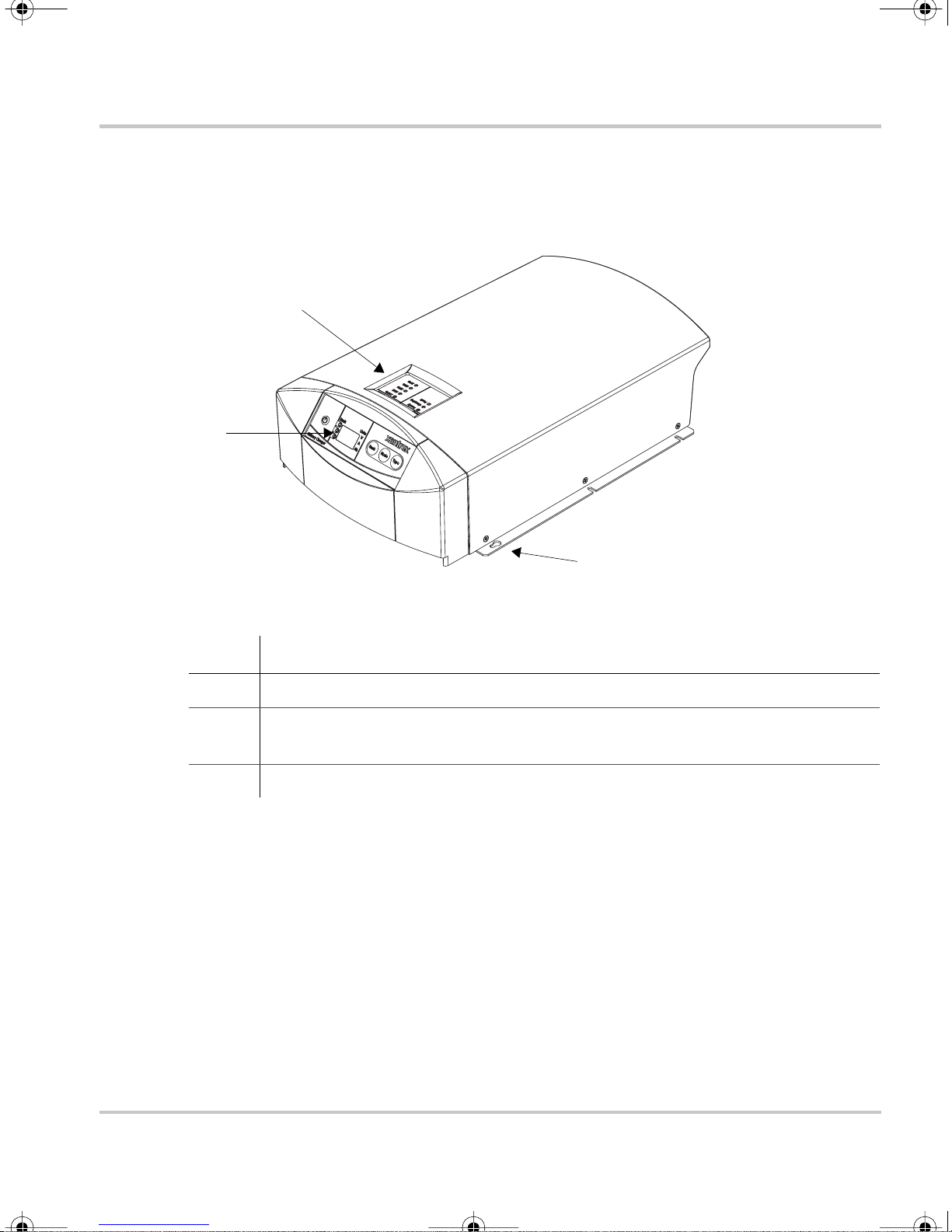
XC Series Appearance
This section describes the parts of the XC Series. Figure 1-2 shows the XC Series.
2
1
XC Series Appearance
3
Figure 1-1
Item Description
1 Remote display for all programming f unctions and monitoring of the XC Series.
2 Onboard status panel for monitoring charger status and charging current at the
3 Mounting flanges
XC Series
XC Ser ies when the remote display is mounted remotely from the charger.
975-0187-01-01 1–3
XC_Cha rger_Owner .book Page 4 Friday, August 12, 2005 3:23 PM
Introduction
Infor m ation Centers of the XC Serie s
Remote Display
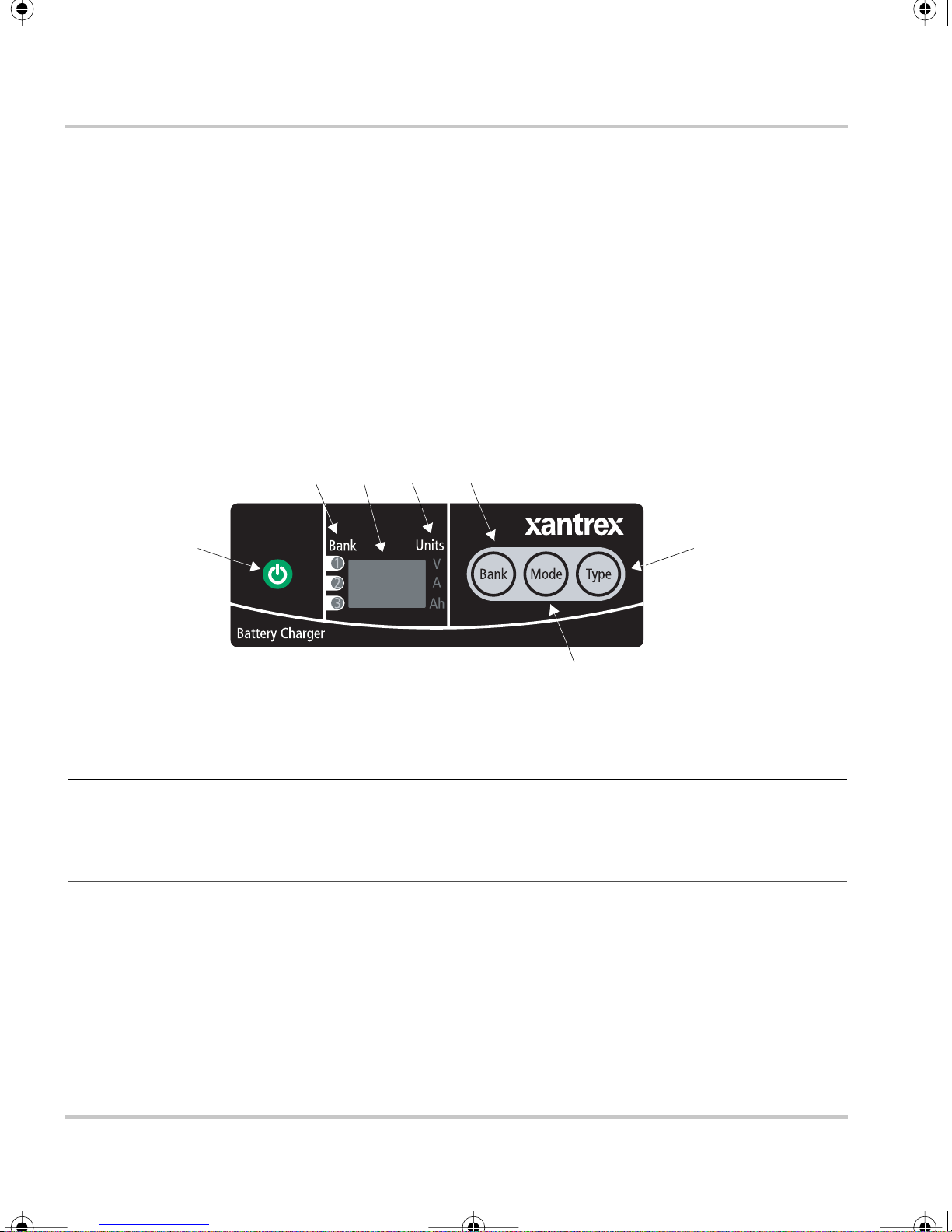
This section descr ibes the parts of the remote display of the XC Series. The remote
display ca n be rotated 180°, or it c an be removed and r emotely mounted up to 20 m
(65 ft) from the XC Serie s for convenience. Figure 1-2 shows the remote display.
A “press and hold” action on the remote display means that the button must be held
down for more than 2 seconds in order to send the instruction. A “press” action on
the remote display means that the button must be pressed and released before 2
seconds have elapse d.
2 3 4 5
1
Figure 1-2
Item Description
1
2 Battery bank indicator lights
ON/STANDBY push button
• Press to turn on or dis able the charger while AC power is connected
• Press and hold to ap ply s election when in setup or equalization mode
• Press to show battery bank voltages when AC is disconnected
• Illuminate to show which bank has been sele cted for setup or status display
• Illuminate during a fault or warning to show which bank has the fault or warning, or
illuminate all three if th e charger itself has the faul t or war n ing
XC Series Remote Display
6
7
1–4 975-0187-01-01

XC_Cha rger_Owner .book Page 5 Friday, August 12, 2005 3:23 PM
Item Description
3 Alpha-numeric display shows
• Configuration
• Fault or warning mess ages (see Table 4-2 on page 4–4)
• Battery bank volt age and current
• Type of charging (2 stage or 3 stage)
• Sta te of charge
4 Units indi cator lights
• Illuminate to show unit of measure for the numeric read-out on the alpha -numeric display
Information Centers of the XC Series
5
BANK selection pus h button
• Press to select a bank during setup
• Press at the same time as
6
TYPE selection push button
MODE to enter o r exit equalization mod e.
• Press to selec t flooded (lead acid), gel, AGM, or lead calcium batteries.
7
MODE selection pus h button
• Pre ss to sele ct c harg i n g st at e du r i ng s et u p : 2 st ag e o r 3 stag e.
• Press at the same time as
BANK to enter or exit equalization mode.
• Press and hold to enter setup.
The indicator li ghts and dis pla y are also use d to indicate error codes. See Chapter 4,
“Troubleshooting” for a list of faults and how to clear them.
975-0187-01-01 1–5

XC_Cha rger_Owner .book Page 6 Friday, August 12, 2005 3:23 PM
Introduction
Onboard Status Panel
This section describes the parts of the onboard status panel of the XC Series.
Figure 1-3 shows the panel.
2
3
4
1
Figure 1-3
Item Description
1 Charge Current
• Displays the output charge c urrent in % of charger m aximum for the bank being charged
• 100% indicator light flashes to indicate batte r y temperature too high (> 50 °C, 122 °F)
• 10% indicator light flashes to indic ate battery temperature too low (< 0 °C, 32 °F)
• 25% indicator light flashes to indicate that a bat tery has been disqualified (see page 3–4)
2
3
4
Charger Status -
• Ready indicator light illuminated indicates all batteries are fully c harged, and are now in
float or rest
Charger Status -
• Charging indicator ligh t illuminated indicates unit is performing a normal cha rge cycle
• Charging indi cator lig ht flash ing indi cates that the unit is perform ing an equali zati on cycle
Charger Status -
• Fault indica tor light continuously illum inated indicates any fault condition that prevents
the XC S eries from charging one or more batterie s, but is not a charger fai lure - remote
display shows details of fault
• Fault indicator light flashing indicates the XC Series has experienced a charger failure remote display shows
XC Series Onboard Stat us Panel
READY
CHARGING
FAULT
err
followed by
CHf
1–6 975-0187-01-01
XC_Cha rger_Owner .book Page 7 Friday, August 12, 2005 3:23 PM
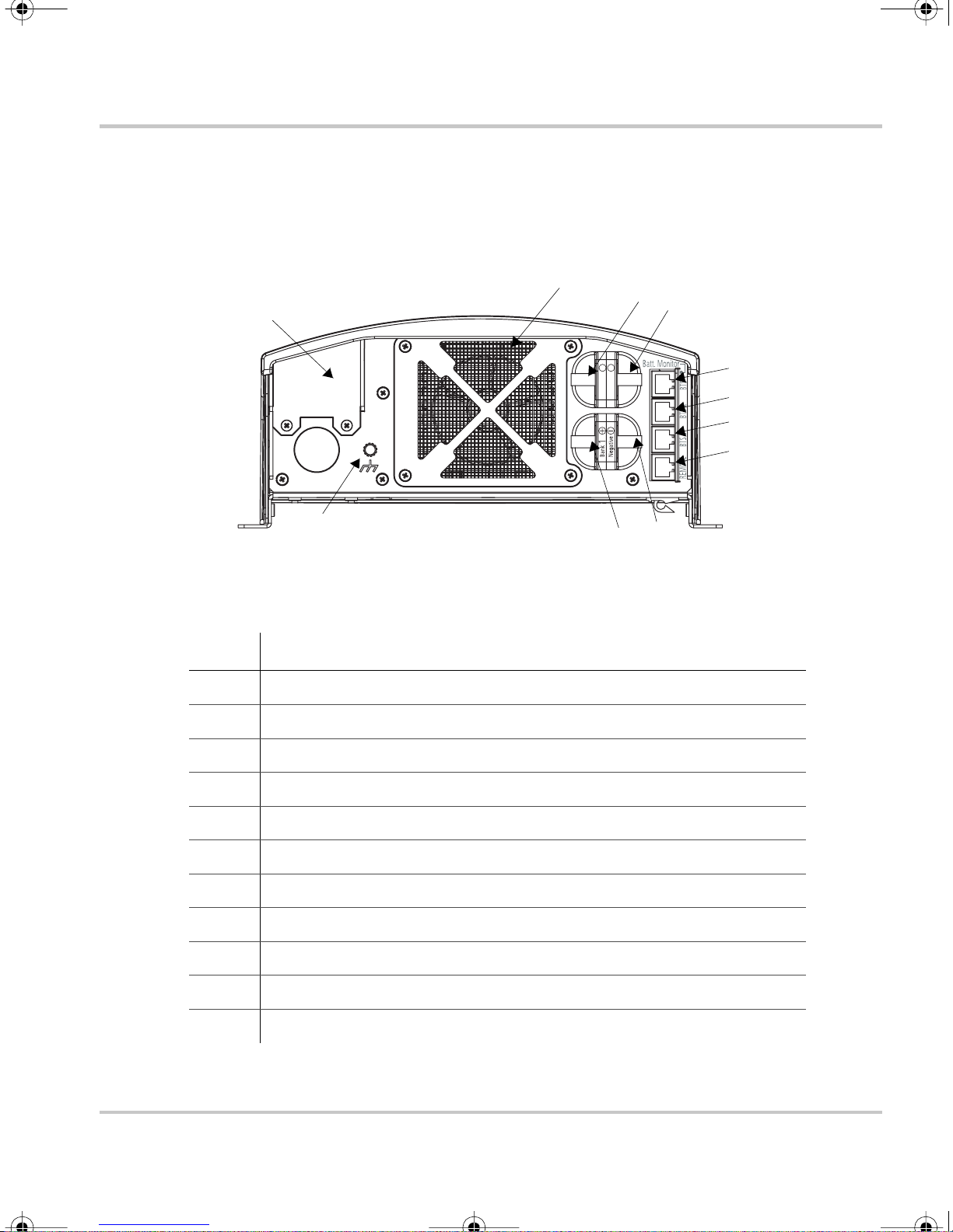
Rear Panel
This section de scribe s the pa rts of the rear panel of the XC S eries. Figure 1-4 shows
the rear panel.
Rear Panel
9
7
11
++
2
Bank3Bank
Figure 1-4
10
XC Series Rear Panel
5
6
Item Description
1 Remote display communication connector
2 BTS1 (battery temperature sens or for bank 1) connector
8
2
3
4
1
3 BTS2 (battery temperature sens or for bank 2) connector
4 BTS3 (battery temperature sens or for bank 3) connector
5 Battery negative, common for all 3 banks (6 mm stud)
6 Battery posi tive for bank 1 (6 mm stu d)
7 Battery posi tive for bank 2 (6 mm stu d)
8 Battery posi tive for bank 3 (6 mm stu d)
9 Fan ass e mb l y
10 Chassis ground (ear th) for DC wiring
11 AC wiring access panel
975-0187-01-01 1–7
XC_Cha rger_Owner .book Page 8 Friday, August 12, 2005 3:23 PM
Introduction
Preparing for Installation
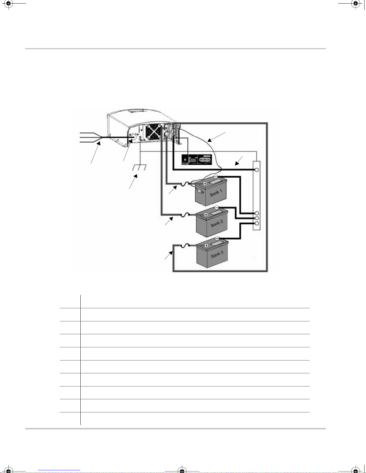
The XC Series is designed to be permanently mounted. Figure 1-1 shows a typical
installation with three batteri es, a BTS and a remote display. It also shows the AC
and DC wiring and protection device s required for a successful installation.
L
N
G
1
Figure 1-5
2
10
XC Series System
8
5
4
5
4
5
4
9
3
6
6
6
7
1 AC mains source with correct size and type of circuit break er
2 AC input wiring compartment
3 DC negative cable
4 DC positive cables
5 DC circuit bre aker or DC fuse and disconnect
6 Battery or ba ttery bank
7 Engine ground bus or DC negative bus
8 Remote display pa nel
9 Battery temperature sensor (#1 is standard equipment. #2 a nd #3 are optional)
10 DC chassis ground (ea rth)
1–8 975-0187-01-01

XC_Cha rger_Owner .book Page 9 Friday, August 12, 2005 3:23 PM
Tools and Materials
To mount and connect the XC Series you need the following tools:
• 10 mm wrench or socket for the DC terminals and ground stud
• Phillips screwdriver for securing the AC wiring compartment cover
• power drill
• drill bit fo r pilot holes for mounting screws
• wire stripper
• manufacturer's recommended crimp tool for any crimp terminals that are being
used
You need the foll ow in g mate ri als:
• 3 conductor AC input wiring
Use the inf ormation in “AC Wiring” on page 1–13 and your local electr ical
codes to determine the corr ect wire and breaker or fuse.
Preparing for Installation
• AC cable strain relief (if the one inc luded is not sufficient for your local
electrical code requirements)
• appropri atel y sized D C ca bles for each b atte ry, with suitable connectors at the
battery end
• appropria tely sized DC chassis ground (earth) with suitable connectors
• ring termin als to fit 6 mm (1/4 in.) studs at the charger end
• DC fuse and disconnect or circuit breaker for each battery bank
• mounting hardware, 3 mm (#6) corrosion resistant 6 pieces.
• other means to route and secure AC and DC wiring
975-0187-01-01 1–9

XC_Cha rger_Owner .book Page 10 Friday, August 12, 2005 3:23 PM
Introduction
Location
Install the XC Series in a location that meets the foll owing requirements:
Condition Requirement
Dry The XC Series must be installed in a dry location not subject to rain, spray or splashing
bilge water.
Clean The XC Series should not be exposed to metal filings or any other form of conductive
contamination.
Cool The ambient air temper ature should be between 0 °C - 50 °C (32 °F - 122 °F) for best
performance.
Ven t il at ed Ther e mus t be at le as t 76 mm (3 in . ) o f clearance on each en d o f the XC Series f or ai r
flow. Ventilation openings on the unit must not be obstructe d. If mounting in a tight
fitt i ng co mp artm en t, th e co m p a rt m e n t m u st be v en tilat ed w it h cut -outs to prevent
overheating.
Safe This battery charger is ignition protected, so it can be installed in areas containing
gasoline tanks or fittings which usually require ignition protected equipment. Xantrex
recommends, however, that it is safe st not to install electrical equipment in these areas.
Close to
batteries
The XC Series should be ins talled as close as possible to the batteries, but not in the
same compartment to prevent excess corrosion. Avoid exces sive cable leng ths and use
the recommended wire sizes . Xant rex recommends <3% wire voltage drop (r ound
circuit) on battery cables under ful l load.
When planning where and how to mount the XC Series, be sure the installati on
allows the char ger to be mounted in one of the permitted vertica l or horiz ontal
orientations.
For marine install ations, only the mounting configur ations with a check mark in
Figure 1-6 meet the North American an d European marine requirements. Marine
products are requi red to meet drip tests, to ensure safety in the presenc e of
condensatio n. I f you are cert ain your installation is not subject to moisture,
configuration d) in Figure 1-6 may be used.
1–10 975-0187-01-01

XC_Cha rger_Owner .book Page 11 Friday, August 12, 2005 3:23 PM
a) b)
Preparing for Installation
Vertical
c) d)
Horizontal
Figure 1-6
XC Series Mounting Orientations
Vertical - this c onfig uration i s uns afe and
should not be used
Vertical - this configuration may be used
in an envi ronment wh ich i s dry and cl ean
only (non-marine)
975-0187-01-01 1–11
XC_Cha rger_Owner .book Page 12 Friday, August 12, 2005 3:23 PM
Introduction
Wiring Requirements
WARNING
W i r e and fuse sizes are dictated b y electrical standards. Diffe rent standards apply in
different countries and differ ent types of installations, for ex ample, boat, home or RV. It is
the responsibility of the installer to ensure that the installation complies with al l applicable
standards.
CAUT ION
Ensure that both wires and fuses are cor rec tly sized.
Maximum conti nuous curre nt ava ilabl e fro m the char ger may be an additi ona l 6–10% a bov e
the nominal current rating of the charger. Output current may also vary depending on
ambient temperature conditions.
DC Wiring
The following two tables show some typic al wire sizes, based on 3% voltage drop
(round circui t), 75 °C (167 °F) rated wire and wiring being inside the engine
compartment – assumed ambient of 50 °C (122 °F).
Table 1-1
Wire Len g th
(
maximum length one way) Wire Size (AWG and mm
feet meters XC3012 XC5012 XC2524 XC1524
51.5No. 10
7.5 2.25 No. 8
20 6 No. 6
DC Wiring Requirements
2
5mm
2
8mm
13 mm
2
No. 6
13 mm
No. 6
13 mm
No. 4
19 mm
2
)
No. 10
2
5mm
2
No. 10
2
5mm
2
No. 10
2
5mm
2
No. 12
3mm
No. 12
3mm
No. 12
3mm
2
2
2
1–12 975-0187-01-01
 Loading...