

Page 1
XC_Cha rger_Owner .book Page 1 Friday, August 12, 2005 3:23 PM
Xantrex
XC3012, XC5012,
XC1524 and XC2524
Battery Charger
Owner’s Guide
12 V / 30 A
12 V / 50 A
24 V / 15 A
24 V / 25 A
Page 2

XC_Cha rger_Owner .book Page 2 Friday, August 12, 2005 3:23 PM
Page 3

XC_Cha rger_Owner .book Page i Frida y, August 12, 2005 3:23 PM
Xantrex XC3012, XC5012,
XC1524 and XC2524
Battery Charger
Owner’s Guide
Page 4

XC_Cha rger_Owner .book Page ii Friday, August 12, 2005 3:23 PM
About Xantrex
Xantrex Technology Inc. is a world-leading supplier of advanced power electronics and controls with
products from 50 watt mobi le units to one MW util ity -sca le syste ms for wind, sol ar, batteries, fuel cells,
microturbin es, a nd backup power applic ations in bot h grid- conn ecte d and stand-a lone syst ems. Xantrex
products include inverters, battery chargers, programmable power supplie s, and variable speed drives
that convert, supply, control, clean, and dis tribute electrical power.
Trademarks
Xantrex XC3012, XC5012, XC1524 and XC2524 Battery Charger is a trademark of Xa ntrex
International. Xantrex is a registe r ed trademark of Xantrex Inter national.
Other trademarks, regist ered trademarks, and product names are the prope rty of their respective owners
and are us ed herein for identification purposes only.
Notice of Copyright
Xantrex XC3012 , XC5012, XC1524 and XC2524 Battery Charge r Owner’s Guide© August 2005
Xantrex International. All rights reserved.
Disclaimer
UNLESS SPECIFICALLY AGREED TO IN WRITING, XANTREX TECHNOLOGY INC.
(“XANTREX”)
(a) MAKES NO WARRANTY AS TO THE ACCURACY, SUFFICIENCY OR SUITABILITY OF
ANY TECHNICAL OR OTHER INFORMATION PROVIDED IN ITS MANUALS OR OTHER
DOCUMENTATION.
(b) ASSUMES NO RESPONSIBILITY OR LIABILITY FOR LOSS OR DAMAGE, WHETHER
DIRECT, INDIRECT, CONSEQUENTIAL OR INCIDENTAL, WHICH MIGHT ARISE OUT OF
THE USE OF SUCH INFORMATION. THE USE OF ANY SUCH INFORMAT ION WILL BE
ENTIRELY AT THE USER’S RISK.
Date and Revision
August 2005 Revision B
Part Number
975-0187-01-01
Contact Information
Phone: 1 800 670 0707 (toll free North America)
+34 93 470 5330 (Europe)
1 360 925 5097 (direct and rest of world)
Fax: 1-800 994 7828 (toll free North America)
+34 93 473 6093 (Europe)
1 360 925 5143 (direct and rest of world)
Email: customerservice@xantrex.com (North America)
support.europe@xantrex. com (Europe)
customerservice@xantrex.com (rest of world)
W eb: www.xantrex.com
Page 5

XC_Cha rger_Owner .book Page iii Friday, Au gust 12, 2005 3:23 PM
About This Guide
Purpose
The purpose of this Owner’ s Guide is to provide explanations and procedures for
installi ng, ope rating, maintaining, and troubleshooting the Xantrex XC3012,
XC5012, XC1524 a nd XC2524 Battery Charger.
Scope
The Guide provides safety guidelines, detailed planning and setup information,
procedures for installing the charger, as well as infor mation about operating and
troubleshooting the unit. It does not provide details about particular brands of
batteries. Consult individual battery manufacturers for this information.
Audience
The Guide is intended for anyone who needs to install and operate the Xantrex
XC3012, XC5012, XC1524 and XC2524 Battery Charger. Installers should be
certified te chn i cian s or elect ri cians.
Organization
This Guide is organized into 4 chapters and 1 appendix:
Chapter 1, “Introduction”: Chapter 1 describes the XC Series standard features. It
also provides infor mation to prepare for installation of the XC Series.
Chapter 2, “Installation”: Chapter 2 provides procedures for installing, testing and
configuring the XC Series.
Chapter 3, “Operation”: Chapter 3 describes the opera ting states and provides
procedures for charging a battery and perfor ming an equalization.
Chapter 4, “Troubleshooting”: Chapter 4 contains informa tion on error codes and
procedures for troubleshooting your XC Series charger.
Appendix A, “Specifications”: Appendix A details the specifications for the
XC Series.
iii
Page 6
XC_Cha rger_Owner .book Page iv Frida y, August 12, 2005 3:23 P M
About This Guide
Conventions U sed
The following conventions are used in this guide.
WARNING
Warnings identify conditions or practices that co uld result in personal injury or loss of life
CAUT ION
Cautions identify conditions or practi ces that could result in damage to the unit or other
equipment.
Important:
serious as a caution or warning.
This Guide contains informati on for four versions of the XC Series.
The Xantrex XC3012 Battery Charge r (12 V, 30 A) will be referred to as the
XC3012 when it is being reference d individually.
The Xantrex XC5012 Battery Charge r (12 V, 50 A) will be referred to as the
XC5012 when it is being reference d individually.
The Xantrex XC1524 Battery Charge r (24 V, 15 A) will be referred to as the
XC1524 when it is being reference d individually.
The Xantrex XC2524 Battery Charge r (24 V, 25 A) will be referred to as the
XC2524 when it is being reference d individually.
When the Xantrex XC3012, XC5012, XC1524 and XC2524 Battery Chargers are
being refere n ced toget h er, they will be referred to as the XC Series.
These notes describe things which are im portant for you to know, but not as
Relat ed Informatio n
You can find more information about Xantrex Technology Inc. as well as its
products and servi ces at www.xantrex.com
iv 975-0187-01-01
Page 7
XC_Cha rger_Owner .book Page v Friday, August 12, 2005 3:23 PM
Important Safety Instructions
WARNING
This chapter contains important safety and operating instructions as prescribed by safety
standards for chargers used in RV and marine applications. Read an d keep this Owner’s
Guide for future reference.
1. Before installing or using the Xantrex XC3012, XC5012, XC1524 or XC2524
Battery Char ger (XC Series), read all instr uctions and cautionary markings on
the XC Series, the batteries, and all appropr iate sections of this guide.
2. Do not expos e the XC Series to rain, snow, spray, or bilge wate r. To reduce risk
of fire hazard, do not cover or obst ruct the ventilation openings. Do not install
the XC Series in a zero -c le ara n ce comp a rt me nt. Overheating ma y resul t.
3. Use only attachments rec ommended or sold by Xantrex. Doing otherwise may
result in a risk of fire, electric shock, or injury to persons.
4. The XC Series is designed to be permanently connected to the AC and DC
electric al systems. Xantrex recommends that all wiring be done by a certified
technician or electrician to ensure compliance with the local and national
electrical codes relevant to your installation. I t is the responsibility of the
installer to ensure that the installation of the XC Ser ies complies with all
relevant el ectri ca l cod es.
5. To avoid a risk of fire and electric shock, make sure that existing wiring is in
good condition and that wire is not undersiz ed. Do not operate the XC Series
with damaged or substandard wiring.
6. Do not disassemble the XC Serie s. I t contains no user-serviceable parts.
Attempt ing t o serv ice t he X C Series your self may res u lt in a risk of elec tric al
shock or fire.
NOTE: Disassembling the XC Series will void your warranty.
7. To reduce the risk of electrical shock, disconne ct both AC and DC power from
the XC Series before attempting any maintenance or cleaning or bef ore
working on any circuits connected to the XC Series. Turning the XC Series off
using the remote displ ay will not reduce this risk.
v
Page 8
XC_Cha rger_Owner .book Page vi Frida y, August 12, 2005 3:23 P M
Safety
8. The XC Series is provided with an AC ground conductor that must be
connected to the AC input ground and a DC ground stud which must be
connected to the DC system ground.
9. For marine applicat ions in the United States, external connections to the
charger shall comply with the United States Coast Guard Electrical Regulations
(33CFR183, Sub part 1).
Explosive Gas and Battery Prec autions
W ARNING: Explosion or fire ha zard
1. Read this guide and follow the instructions exactly before installing or using
your XC Series.
2. Follow all instru ctions published by the battery manufacturer and the
manufacturer of the equipment in which the battery is instal led.
3. Working in the vicinity of lead-acid batteries is dangerous. Batte ries generate
explosive gases dur ing normal operation.
4. The XC Series has been approved as Ignition Protected. It may be installed in
areas containing ga soline tanks and fittings which require Ignition Prote cted
equipment. Xantrex recommends, nevertheless, that it is safest not to install
electrica l equi p me nt in the s e area s.
5. Make sure the area around the battery is well ventilated.
6. Never smoke or allow a spark or flame near the engine or batteries.
7. Use caution to reduce the risk of dropping a metal tool on the battery. It could
spark or short circu it the battery or other electric al parts and could cause an
explosion.
8. Remove all metal items, like rings, bracelets, and watc hes when working with
lead-acid batteries. Lead-acid batteries produce a short circuit current high
enough to weld metal, causing a severe skin burn.
9. Have someone within range of your voic e or clos e enough to come to your aid
when you work near a lead-acid battery.
vi 975-0187-01-01
Page 9

XC_Cha rger_Owner .book Page vii Friday, August 12, 2005 3:23 PM
10. Have plenty of fresh water and soap nearby in case battery acid contacts skin,
clothing, or eyes.
11. Wear complete eye protection and clothing protection. Avoid touching your
eyes while w ork i ng near batt eri es.
12. If battery acid c ontac ts skin or clothin g, wash immedia tely wit h soap a nd water.
If acid enters your eye, immediate ly flood it with running col d water for at least
twenty minutes and get m edical attention immediately.
13. If you need to remove a battery, always remove the ground terminal from the
battery firs t. Make sure al l accessories are off to reduce the possibility of
causing a spark.
Safety
FCC Information
This equipment has been tested and found to comply with the limits for a Class B
digital device, pursua nt to part 15 of the FCC Rules. These limits a re designed to
provide reasonable protection again st harmful interference in a residential
installati on. Thi s equipment g enerat es, uses, and can radi ate radio f requenc y ener gy
and, if not installed and used in accordance with the instructions, may cause
harmful interf erence to radio communications .
However , there is no guarantee that interference will not occur in a particular
installation. If this equipment does cause harmful int erference to radio or television
reception, which can be determ ined by turning the equipment off and on, the user is
encouraged to try to correct the interference by one or more of the following
measures:
• Reorient or relocate the receiving antenna.
• Increase the separation between the equipment and receiver.
• Connect the equipment into an outlet on a circuit different from that to which
the receiver is conne cted.
• Consult the deal er or an experienced radio/TV techni cian for help.
975-0187-01-01 vii
Page 10

XC_Charger_Owner.book Page viii Friday, August 12, 2005 3:23 PM
viii
Page 11

XC_Cha rger_Owner .book Page ix Frida y, August 12, 2005 3:23 P M
Contents
Important Safety Instructions
Explosive Gas and Battery Precautions - - - - - - - - - - - - - - - - - - - - - - - - - - - - - - - - vi
FCC Information - - - - - - - - - - - - - - - - - - - - - - - - - - - - - - - - - - - - - - - - - - - - - - -vii
1
Introduction
Xantrex XC3012, XC5012, XC1524 and XC2524 Battery Charger Features - - - - - -1–2
XC Series Appearance- - - - - - - - - - - - - - - - - - - - - - - - - - - - - - - - - - - - - - - - - - - 1–3
Information Centers of the XC Series- - - - - - - - - - - - - - - - - - - - - - - - - - - - - - - - - 1–4
Remote Display - - - - - - - - - - - - - - - - - - - - - - - - - - - - - - - - - - - - - - - - - - - - 1–4
Onboard Status Panel - - - - - - - - - - - - - - - - - - - - - - - - - - - - - - - - - - - - - - - - 1–6
Rear Panel - - - - - - - - - - - - - - - - - - - - - - - - - - - - - - - - - - - - - - - - - - - - - - - - - - - 1–7
Preparing for Installation - - - - - - - - - - - - - - - - - - - - - - - - - - - - - - - - - - - - - - - - - 1–8
Tools and Materials - - - - - - - - - - - - - - - - - - - - - - - - - - - - - - - - - - - - - - - - - 1–9
Location - - - - - - - - - - - - - - - - - - - - - - - - - - - - - - - - - - - - - - - - - - - - - - - - 1–10
Wiring Requirement s - - - - - - - - - - - - - - - - - - - - - - - - - - - - - - - - - - - - - - - 1–12
DC Wiring - - - - - - - - - - - - - - - - - - - - - - - - - - - - - - - - - - - - - - - - - - - - 1–12
AC Wiring - - - - - - - - - - - - - - - - - - - - - - - - - - - - - - - - - - - - - - - - - - - - 1–13
Battery Bank Size Require ments - - - - - - - - - - - - - - - - - - - - - - - - - - - - - - - - 1–14
2
Installation
Installing the XC Series - - - - - - - - - - - - - - - - - - - - - - - - - - - - - - - - - - - - - - - - - - 2–2
Installation Sequence - - - - - - - - - - - - - - - - - - - - - - - - - - - - - - - - - - - - - - - - 2–2
Pre-Installing DC Wiring - - - - - - - - - - - - - - - - - - - - - - - - - - - - - - - - - - - - - - 2–3
Pre-Installing AC Wiring - - - - - - - - - - - - - - - - - - - - - - - - - - - - - - - - - - - - - - 2–4
Mounting the Remote Display - - - - - - - - - - - - - - - - - - - - - - - - - - - - - - - - - - 2–7
Mounting - - - - - - - - - - - - - - - - - - - - - - - - - - - - - - - - - - - - - - - - - - - - - - - - 2–8
Grounding - - - - - - - - - - - - - - - - - - - - - - - - - - - - - - - - - - - - - - - - - - - - - - - - 2–9
Final Connection s - - - - - - - - - - - - - - - - - - - - - - - - - - - - - - - - - - - - - - - - - 2–10
Final DC Connections - - - - - - - - - - - - - - - - - - - - - - - - - - - - - - - - - - - - 2–11
Final AC Connections - - - - - - - - - - - - - - - - - - - - - - - - - - - - - - - - - - - - 2–12
Powering Up - - - - - - - - - - - - - - - - - - - - - - - - - - - - - - - - - - - - - - - - - - - - - 2–12
975-0187-01-01 ix
Page 12

XC_Cha rger_Owner .book Page x Friday, August 12, 2005 3:23 PM
Contents
Installing Optional Accessories- - - - - - - - - - - - - - - - - - - - - - - - - - - - - - - - - - - - 2–13
Battery Temperat ure Sensor - - - - - - - - - - - - - - - - - - - - - - - - - - - - - - - - - - 2–13
Drip Protectio n Rubber Boots - - - - - - - - - - - - - - - - - - - - - - - - - - - - - - - - - 2–14
Configuring the XC Series- - - - - - - - - - - - - - - - - - - - - - - - - - - - - - - - - - - - - - - 2–15
3
Operation
About Charging - - - - - - - - - - - - - - - - - - - - - - - - - - - - - - - - - - - - - - - - - - - - - - - 3–2
Multiplex 3-Sta ge Charging - - - - - - - - - - - - - - - - - - - - - - - - - - - - - - - - - - - - 3–2
Sequential 2-Stage Charging - - - - - - - - - - - - - - - - - - - - - - - - - - - - - - - - - - - 3–3
Charging Overview - - - - - - - - - - - - - - - - - - - - - - - - - - - - - - - - - - - - - - - - - 3–3
Charging Batteries - - - - - - - - - - - - - - - - - - - - - - - - - - - - - - - - - - - - - - - - - - - - - 3–6
Equalizing Flooded Batteries - - - - - - - - - - - - - - - - - - - - - - - - - - - - - - - - - - - - - - 3–8
Transitioning the XC Series to On, Disabled or Off - - - - - - - - - - - - - - - - - - - - - - 3–10
Accessing Charger I nformation - - - - - - - - - - - - - - - - - - - - - - - - - - - - - - - - - - - 3–11
Reading Remote Display and Onboard Status Indicator Lights - - - - - - - - - - - 3–11
Reporting While Chargi ng or Equalizing - - - - - - - - - - - - - - - - - - - - - - - - - - 3–13
Reporting While Batte ry Monitoring - - - - - - - - - - - - - - - - - - - - - - - - - - - - - 3–14
Reporting While Disab led - - - - - - - - - - - - - - - - - - - - - - - - - - - - - - - - - - - - 3–14
Using A Generator As Source Power - - - - - - - - - - - - - - - - - - - - - - - - - - - - 3–15
4
Troubleshooting
Care and Maintenance- - - - - - - - - - - - - - - - - - - - - - - - - - - - - - - - - - - - - - - - - - - 4–2
Indicator Light Flashing Sequences- - - - - - - - - - - - - - - - - - - - - - - - - - - - - - - - - - 4–3
Error Messages on Remote Display- - - - - - - - - - - - - - - - - - - - - - - - - - - - - - - - - - 4–4
Problem Solving - - - - - - - - - - - - - - - - - - - - - - - - - - - - - - - - - - - - - - - - - - - - - - 4–7
A
Specifications
Physical Specifications - - - - - - - - - - - - - - - - - - - - - - - - - - - - - - - - - - - - - - - - - -A–2
Electrical Specifications - - - - - - - - - - - - - - - - - - - - - - - - - - - - - - - - - - - - - - - - -A–2
AC Input Specifications - - - - - - - - - - - - - - - - - - - - - - - - - - - - - - - - - - - - - - - - -A–3
Temperature Specifications - - - - - - - - - - - - - - - - - - - - - - - - - - - - - - - - - - - - - - -A–4
Protection Features - - - - - - - - - - - - - - - - - - - - - - - - - - - - - - - - - - - - - - - - - - - - -A–4
Approvals - - - - - - - - - - - - - - - - - - - - - - - - - - - - - - - - - - - - - - - - - - - - - - - - - - -A–5
Warranty and Product Information
x 975-0187-01-01
- - - - - - - - - - - - - - - - - - - - - - - - - - WA–1
Page 13

XC_Cha rger_Owner .book Page 1 Friday, August 12, 2005 3:23 PM
1
Introduction
Chapter 1 describes the XC Series standard features. It
also provides information to prepare for installation of
the XC Ser i es.
Page 14

XC_Cha rger_Owner .book Page 2 Friday, August 12, 2005 3:23 PM
Introduction
Xantrex XC3012, XC5012, XC1524 and XC 2524 Battery
Charger Fe atures
The XC Series provides the following standard features:
• three full current rated, independently controlled outputs which enable it to
charge thr ee dif ferent ba tter ies or batter y banks. Each bank can be of a diffe rent
battery type, stage of charging, and temperature compensation
• one battery temperature sensor (BTS) is included. Optional BTSs may be
purchased for the other two outputs, to pr ovide complete optimal battery
charging to each battery or bank
• battery moni toring functions while in float mode or rest mode
• correct c harging voltage for your batt eries when connec ted to almost any single
phase AC power outlet in the world
• invertable remote display panel which can also be removed from the char ger
and mounted up to 20 m (65 ft) away for remote contr ol and monitoring
The XC Series provides the following protection features:
• true “fusele ss” reverse polarity protection to guard against continuous reverse
battery polar ity without charger damage
• AC over voltage protection shutdown
• over temperature prote ction shutdown
• electr onic current limiting for prote ction against short circuit on the unit’s
output
• built-in pr otection against accidental connection to a higher battery voltage, up
to 24 VDC
• battery te mperature compensation to 0 °C (32 °F) (with BTS installed)
• igniti on protected rating, enabl ing installation in engine spaces
• isolated design to reduce shock hazard
• automatic charge resumption afte r AC power interruption
1–2 975-0187-01-01
Page 15
XC_Cha rger_Owner .book Page 3 Friday, August 12, 2005 3:23 PM
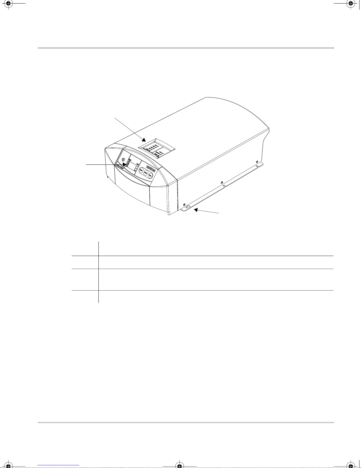
XC Series Appearance
This section describes the parts of the XC Series. Figure 1-2 shows the XC Series.
2
1
XC Series Appearance
3
Figure 1-1
Item Description
1 Remote display for all programming f unctions and monitoring of the XC Series.
2 Onboard status panel for monitoring charger status and charging current at the
3 Mounting flanges
XC Series
XC Ser ies when the remote display is mounted remotely from the charger.
975-0187-01-01 1–3
Page 16
XC_Cha rger_Owner .book Page 4 Friday, August 12, 2005 3:23 PM
Introduction
Infor m ation Centers of the XC Serie s
Remote Display
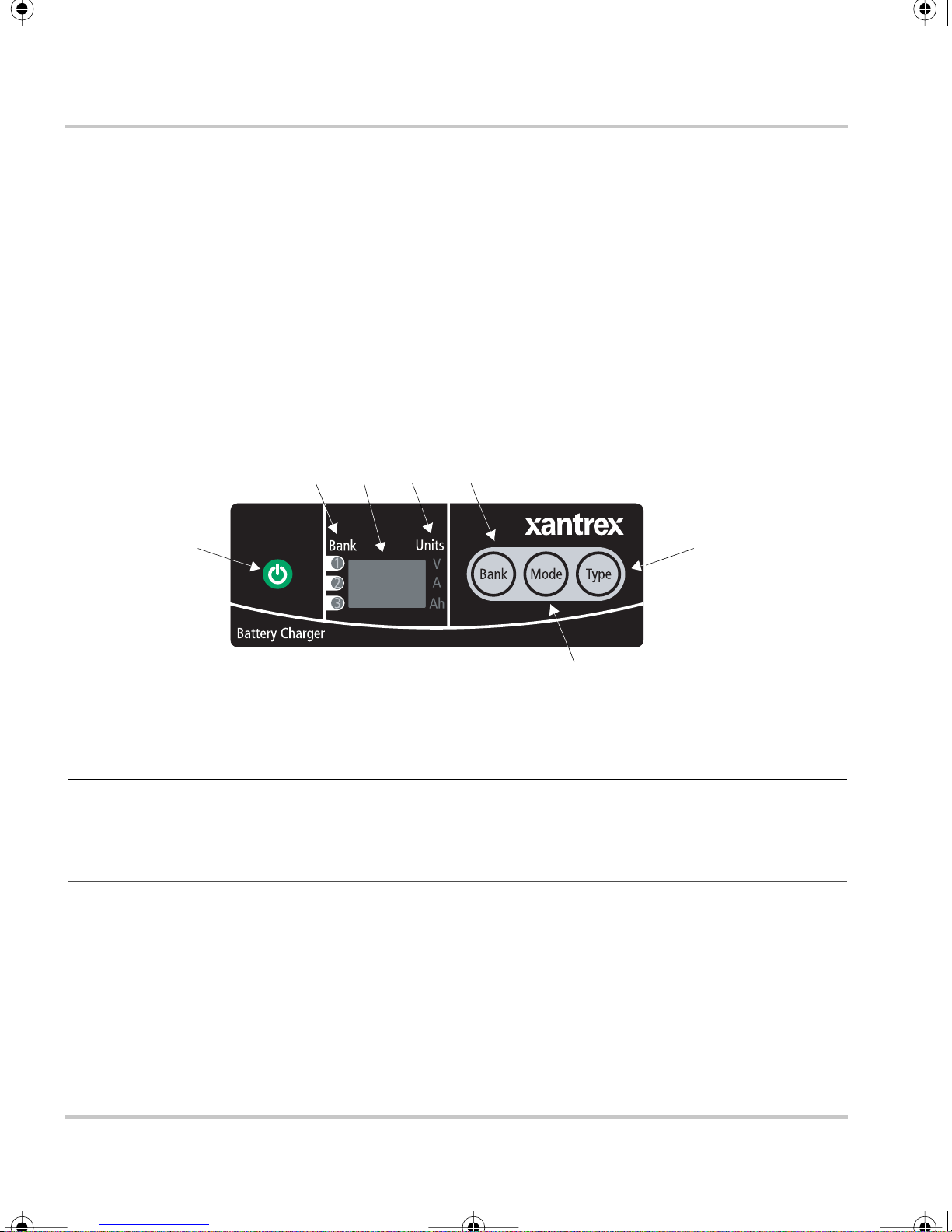
This section descr ibes the parts of the remote display of the XC Series. The remote
display ca n be rotated 180°, or it c an be removed and r emotely mounted up to 20 m
(65 ft) from the XC Serie s for convenience. Figure 1-2 shows the remote display.
A “press and hold” action on the remote display means that the button must be held
down for more than 2 seconds in order to send the instruction. A “press” action on
the remote display means that the button must be pressed and released before 2
seconds have elapse d.
2 3 4 5
1
Figure 1-2
Item Description
1
2 Battery bank indicator lights
ON/STANDBY push button
• Press to turn on or dis able the charger while AC power is connected
• Press and hold to ap ply s election when in setup or equalization mode
• Press to show battery bank voltages when AC is disconnected
• Illuminate to show which bank has been sele cted for setup or status display
• Illuminate during a fault or warning to show which bank has the fault or warning, or
illuminate all three if th e charger itself has the faul t or war n ing
XC Series Remote Display
6
7
1–4 975-0187-01-01
Page 17

XC_Cha rger_Owner .book Page 5 Friday, August 12, 2005 3:23 PM
Item Description
3 Alpha-numeric display shows
• Configuration
• Fault or warning mess ages (see Table 4-2 on page 4–4)
• Battery bank volt age and current
• Type of charging (2 stage or 3 stage)
• Sta te of charge
4 Units indi cator lights
• Illuminate to show unit of measure for the numeric read-out on the alpha -numeric display
Information Centers of the XC Series
5
BANK selection pus h button
• Press to select a bank during setup
• Press at the same time as
6
TYPE selection push button
MODE to enter o r exit equalization mod e.
• Press to selec t flooded (lead acid), gel, AGM, or lead calcium batteries.
7
MODE selection pus h button
• Pre ss to sele ct c harg i n g st at e du r i ng s et u p : 2 st ag e o r 3 stag e.
• Press at the same time as
BANK to enter or exit equalization mode.
• Press and hold to enter setup.
The indicator li ghts and dis pla y are also use d to indicate error codes. See Chapter 4,
“Troubleshooting” for a list of faults and how to clear them.
975-0187-01-01 1–5
Page 18

XC_Cha rger_Owner .book Page 6 Friday, August 12, 2005 3:23 PM
Introduction
Onboard Status Panel
This section describes the parts of the onboard status panel of the XC Series.
Figure 1-3 shows the panel.
2
3
4
1
Figure 1-3
Item Description
1 Charge Current
• Displays the output charge c urrent in % of charger m aximum for the bank being charged
• 100% indicator light flashes to indicate batte r y temperature too high (> 50 °C, 122 °F)
• 10% indicator light flashes to indic ate battery temperature too low (< 0 °C, 32 °F)
• 25% indicator light flashes to indicate that a bat tery has been disqualified (see page 3–4)
2
3
4
Charger Status -
• Ready indicator light illuminated indicates all batteries are fully c harged, and are now in
float or rest
Charger Status -
• Charging indicator ligh t illuminated indicates unit is performing a normal cha rge cycle
• Charging indi cator lig ht flash ing indi cates that the unit is perform ing an equali zati on cycle
Charger Status -
• Fault indica tor light continuously illum inated indicates any fault condition that prevents
the XC S eries from charging one or more batterie s, but is not a charger fai lure - remote
display shows details of fault
• Fault indicator light flashing indicates the XC Series has experienced a charger failure remote display shows
XC Series Onboard Stat us Panel
READY
CHARGING
FAULT
err
followed by
CHf
1–6 975-0187-01-01
Page 19
XC_Cha rger_Owner .book Page 7 Friday, August 12, 2005 3:23 PM
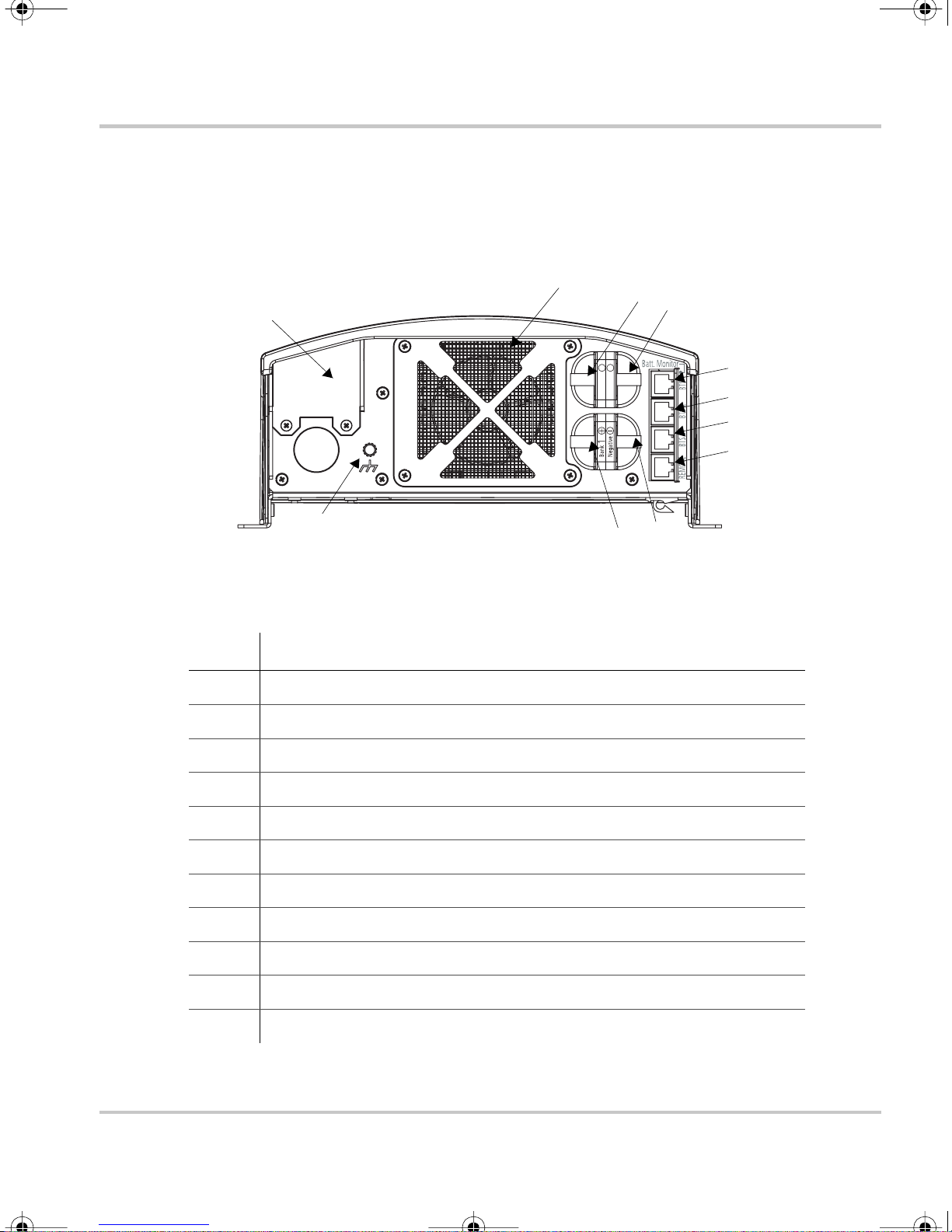
Rear Panel
This section de scribe s the pa rts of the rear panel of the XC S eries. Figure 1-4 shows
the rear panel.
Rear Panel
9
7
11
++
2
Bank3Bank
Figure 1-4
10
XC Series Rear Panel
5
6
Item Description
1 Remote display communication connector
2 BTS1 (battery temperature sens or for bank 1) connector
8
2
3
4
1
3 BTS2 (battery temperature sens or for bank 2) connector
4 BTS3 (battery temperature sens or for bank 3) connector
5 Battery negative, common for all 3 banks (6 mm stud)
6 Battery posi tive for bank 1 (6 mm stu d)
7 Battery posi tive for bank 2 (6 mm stu d)
8 Battery posi tive for bank 3 (6 mm stu d)
9 Fan ass e mb l y
10 Chassis ground (ear th) for DC wiring
11 AC wiring access panel
975-0187-01-01 1–7
Page 20
XC_Cha rger_Owner .book Page 8 Friday, August 12, 2005 3:23 PM
Introduction
Preparing for Installation
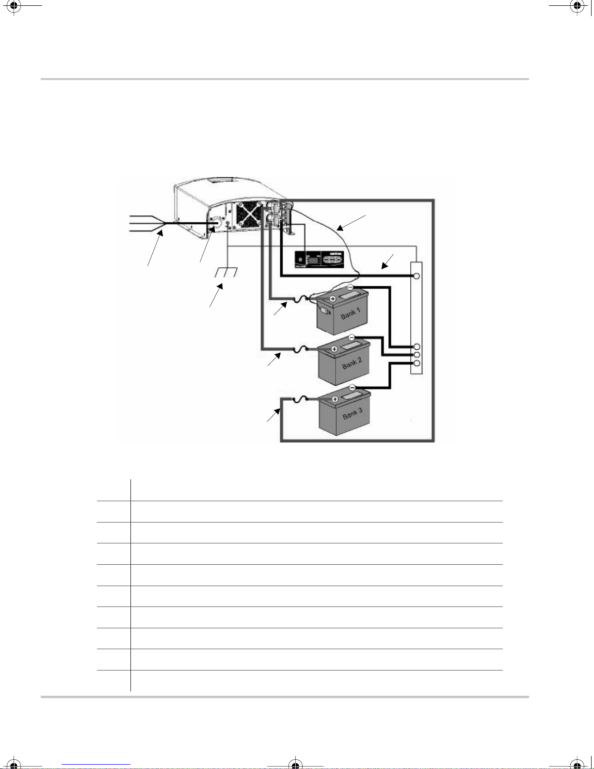
The XC Series is designed to be permanently mounted. Figure 1-1 shows a typical
installation with three batteri es, a BTS and a remote display. It also shows the AC
and DC wiring and protection device s required for a successful installation.
L
N
G
1
Figure 1-5
2
10
XC Series System
8
5
4
5
4
5
4
9
3
6
6
6
7
1 AC mains source with correct size and type of circuit break er
2 AC input wiring compartment
3 DC negative cable
4 DC positive cables
5 DC circuit bre aker or DC fuse and disconnect
6 Battery or ba ttery bank
7 Engine ground bus or DC negative bus
8 Remote display pa nel
9 Battery temperature sensor (#1 is standard equipment. #2 a nd #3 are optional)
10 DC chassis ground (ea rth)
1–8 975-0187-01-01
Page 21

XC_Cha rger_Owner .book Page 9 Friday, August 12, 2005 3:23 PM
Tools and Materials
To mount and connect the XC Series you need the following tools:
• 10 mm wrench or socket for the DC terminals and ground stud
• Phillips screwdriver for securing the AC wiring compartment cover
• power drill
• drill bit fo r pilot holes for mounting screws
• wire stripper
• manufacturer's recommended crimp tool for any crimp terminals that are being
used
You need the foll ow in g mate ri als:
• 3 conductor AC input wiring
Use the inf ormation in “AC Wiring” on page 1–13 and your local electr ical
codes to determine the corr ect wire and breaker or fuse.
Preparing for Installation
• AC cable strain relief (if the one inc luded is not sufficient for your local
electrical code requirements)
• appropri atel y sized D C ca bles for each b atte ry, with suitable connectors at the
battery end
• appropria tely sized DC chassis ground (earth) with suitable connectors
• ring termin als to fit 6 mm (1/4 in.) studs at the charger end
• DC fuse and disconnect or circuit breaker for each battery bank
• mounting hardware, 3 mm (#6) corrosion resistant 6 pieces.
• other means to route and secure AC and DC wiring
975-0187-01-01 1–9
Page 22

XC_Cha rger_Owner .book Page 10 Friday, August 12, 2005 3:23 PM
Introduction
Location
Install the XC Series in a location that meets the foll owing requirements:
Condition Requirement
Dry The XC Series must be installed in a dry location not subject to rain, spray or splashing
bilge water.
Clean The XC Series should not be exposed to metal filings or any other form of conductive
contamination.
Cool The ambient air temper ature should be between 0 °C - 50 °C (32 °F - 122 °F) for best
performance.
Ven t il at ed Ther e mus t be at le as t 76 mm (3 in . ) o f clearance on each en d o f the XC Series f or ai r
flow. Ventilation openings on the unit must not be obstructe d. If mounting in a tight
fitt i ng co mp artm en t, th e co m p a rt m e n t m u st be v en tilat ed w it h cut -outs to prevent
overheating.
Safe This battery charger is ignition protected, so it can be installed in areas containing
gasoline tanks or fittings which usually require ignition protected equipment. Xantrex
recommends, however, that it is safe st not to install electrical equipment in these areas.
Close to
batteries
The XC Series should be ins talled as close as possible to the batteries, but not in the
same compartment to prevent excess corrosion. Avoid exces sive cable leng ths and use
the recommended wire sizes . Xant rex recommends <3% wire voltage drop (r ound
circuit) on battery cables under ful l load.
When planning where and how to mount the XC Series, be sure the installati on
allows the char ger to be mounted in one of the permitted vertica l or horiz ontal
orientations.
For marine install ations, only the mounting configur ations with a check mark in
Figure 1-6 meet the North American an d European marine requirements. Marine
products are requi red to meet drip tests, to ensure safety in the presenc e of
condensatio n. I f you are cert ain your installation is not subject to moisture,
configuration d) in Figure 1-6 may be used.
1–10 975-0187-01-01
Page 23

XC_Cha rger_Owner .book Page 11 Friday, August 12, 2005 3:23 PM
a) b)
Preparing for Installation
Vertical
c) d)
Horizontal
Figure 1-6
XC Series Mounting Orientations
Vertical - this c onfig uration i s uns afe and
should not be used
Vertical - this configuration may be used
in an envi ronment wh ich i s dry and cl ean
only (non-marine)
975-0187-01-01 1–11
Page 24
XC_Cha rger_Owner .book Page 12 Friday, August 12, 2005 3:23 PM
Introduction
Wiring Requirements
WARNING
W i r e and fuse sizes are dictated b y electrical standards. Diffe rent standards apply in
different countries and differ ent types of installations, for ex ample, boat, home or RV. It is
the responsibility of the installer to ensure that the installation complies with al l applicable
standards.
CAUT ION
Ensure that both wires and fuses are cor rec tly sized.
Maximum conti nuous curre nt ava ilabl e fro m the char ger may be an additi ona l 6–10% a bov e
the nominal current rating of the charger. Output current may also vary depending on
ambient temperature conditions.
DC Wiring
The following two tables show some typic al wire sizes, based on 3% voltage drop
(round circui t), 75 °C (167 °F) rated wire and wiring being inside the engine
compartment – assumed ambient of 50 °C (122 °F).
Table 1-1
Wire Len g th
(
maximum length one way) Wire Size (AWG and mm
feet meters XC3012 XC5012 XC2524 XC1524
51.5No. 10
7.5 2.25 No. 8
20 6 No. 6
DC Wiring Requirements
2
5mm
2
8mm
13 mm
2
No. 6
13 mm
No. 6
13 mm
No. 4
19 mm
2
)
No. 10
2
5mm
2
No. 10
2
5mm
2
No. 10
2
5mm
2
No. 12
3mm
No. 12
3mm
No. 12
3mm
2
2
2
1–12 975-0187-01-01
Page 25

XC_Cha rger_Owner .book Page 13 Friday, August 12, 2005 3:23 PM
Over-current protection disconnect
The DC circuit from the battery to the char ger must be equipped with a disconnect
and over-c urrent protection device. The device usually consists of a DC-rated
circuit breake r, a “fused disconnect”, or a separate fuse and disconnect. These
devices must be rated for DC voltage and current. Do not substitute devic es rated
only for AC voltage; they may not operat e properly.
The current ratin g of the DC fuses must be matched to the size of the DC wiring
used, in accor d ance w ith t he appli cab le co des .
The DC chassis ground (earth ) should not be more than one size smaller than the
DC wiring size selected (s ee Table 1-1). Refer to your local electrical codes for
verification.
Preparing for Installation
AC Wiring
The AC wiring must meet the following requi rements before you install the
XC Series:
The AC input wiring for the XC Series should be three-conductor cable, providing a
line, neutral, and ground conductor (or L1, N,
GND) in an outer jacket.
For example, in North America for 120 VAC use a 14 AWG wire with a 15 A
breaker; or typic ally in Europe for 230 VAC use either a 2.5mm
2
wire with a 16 A,
double pole br eaker or fuse o r use 1.5 mm2 wire with a 1 0 A, double pole breaker or
fuse. Note that every jurisdiction will have different requirements, so see the
regulation s for your local jurisdiction to determine which wire size and type is
correct. A sec o nd example:
• for marine applic ations the United States ABYC requires stranded wire, which
is more robust than solid wire when exposed to vibration
• for RV applications, the United States NEC allows solid wire in multi-
conductor cable, but stranded wire will withstand vibration better.
The circuit supplying the XC Series must be protected by the correct size and type
of breaker to meet the code for your local jurisdiction and application. If a fuse is
used, a discon nect swi tch is ne eded ahead o f the fus e.
975-0187-01-01 1–13
Page 26

XC_Cha rger_Owner .book Page 14 Friday, August 12, 2005 3:23 PM
Introduction
Battery Bank Size Requirements
The XC Series is designed to work with a minimum battery bank size. Each bank
should meet the minimum Ah rating shown in Table 1-2.
Table 1-2
Models XC 1524 XC 2524 XC 3012 XC 5012
Minimum Battery
Bank Size (Ah)
Minimum Battery Bank Size
30 50 60 100
1–14 975-0187-01-01
Page 27

XC_Cha rger_Owner .book Page 1 Friday, August 12, 2005 3:23 PM
2
Installation
Chapter 2 provides procedures for installing, testing
and configuring the XC Series.
The unit is packed with the following materials:
• Owner’s Guide
• AC cable strain relief
• Two DC cable boots
• Blank plate for remote display cavity
• One battery temperature sensor (BTS)
• Five # 6 lockwas hers
• Five #6 flatwashers
• Five #6 nuts
After unpacking the unit, record the serial number and
other purchase information on page WA–4 of this
guide.
Page 28

XC_Cha rger_Owner .book Page 2 Friday, August 12, 2005 3:23 PM
Installation
Installing the XC Series
W AR NING: Shock and En ergy Hazards
Be sure to read the safety guidelines and pay attenti on to all cautions and warnings
throughout the installat ion procedure. The ins taller is resp ons ible for ensuring compl iance
with the insta llation codes for your pa rticular application.
Disconnect all sources of AC and DC power before proceeding.
Installation Sequence
To make charger installation quic k and easy, Xantrex recommends tha t the
installation tasks be performed in the following sequence:
1. Select charger mounting position and p lan AC and DC cable routing (page 1–8)
2. Install DC cable runs and fuses or breakers (page 2–3)
3. Make the AC connections at the charger (page 2–4)
4. Mount the remote display and charger in position (page 2–7)
5. Make the final DC and then AC cable connections (including earth grounds)
(page 2–10)
2–2 975-0187-01-01
Page 29

XC_Cha rger_Owner .book Page 3 Friday, August 12, 2005 3:23 PM
Pre-Installing DC Wiring
The procedure for installing the DC wiring applies to a single battery or multiple
batteries or battery banks.
W ARNING: Shock or arc burn hazard
To help prevent accidental shorts or sparks, leave the DC disconnects or breake rs in the Off
position or fuses removed from their fuse holders until installation is com plete.
Installing t he XC Series
Important:
terminals to provide drip protection and incre ased protection from short circuit s. You need
to install the boots before doing any othe r DC wiring. See “To install rubber boots:” on
page 2–14.
Xantrex recommends that you in stall t he r ubber boot s over the XC Series DC
To install DC wiring:
1. Identify the bat tery or bank that most frequently becomes deeply discharged.
This bank will ofte n be a deep cycle battery referr ed to as the House Bank on a
boat, as opposed to an engine Start Battery. This high priority bank should be
connected to bank 1 on the XC Series, which is the default bank.
2. Plan the route that the DC wires will follow, keeping it as short as possible.
Measure and cut the requir ed wire length. Allow some extra length for
connections and to provide slack in the wires.
Note: The con nection to the battery negative circuit may not be at a battery, but
may be at an engine negative bus or a DC negative bus. If in doubt, consult the
boat schematics.
3. Identify the positive wires, by using color-coded wire or by marking both ends
of the wire with c olored ta pe or simi lar k ind of marking. Repeat with a dif f erent
color for the negat ive. Most install at ion codes recommend col oring the positive
red and the negative black.
Important:
bank it is connected to. F or example, bank 1 (–), ba nk 1 (+), bank 2 (–).
Yo u m ay fi n d it he lp f u l to labe l each ca bl e, asso ci a ting it wi t h th e batter y
4. Install a DC circuit breaker or fuse/disconnect in each positive cable close to
each batte ry. For your appli cations a nd juri sdiction , consu lt you r loc al electr ical
codes regarding the distance betwe en th e battery and the disconnect device. Be
sure the breaker is open or fuse is not inserted at this time.
975-0187-01-01 2–3
Page 30

XC_Cha rger_Owner .book Page 4 Friday, August 12, 2005 3:23 PM
Installation
5. Route the wiring to the batteries and to the XC Series, but don’t connect it yet.
A void routing wir ing through an electri cal distributio n panel, battery isolator , or
other device that will a dd voltage drops.
6. Install crimp lugs on each end of the battery cables using the crimp
manufacturer’s instructions and tool.
7. Install rubber boots over the charger end of the DC cables.
Xantrex recommends that you install rubber boots over the XC Series DC
terminals to provide drip protection. Follow the procedure on page 2–14 to
install rubbe r boots.
8. Route the battery temperature sensor from each battery to the charger location.
9. Proceed to “Pre-Installing AC Wiring”.
Pre-Installing AC Wiring
Before connecting AC wiring, make sure the AC source circuit is protecte d by a
breaker switch of the correct size and type, to comply with the electrical code for
your location and appl ication.
To install AC wiring:
1. Disconnect the AC source by turning off the breaker feeding the circuit,
unplugging from sho repower and disconnecting any other power sources (s uch
as a generator).
2. Plan the route that the AC wiring will follow from the source (usually an AC
distribut ion panel) to the XC Series. Measure and cut the required length of
three-condu ctor cable.
For example, in North America for 120 VAC use a 14 AWG wire with a 15 A
breaker; or typic ally in Europe for 230 VAC use either a 2.5mm
16 A, double pole breaker or fuse or use 1.5 mm
breaker or f use. Note that e very jur isdi ction wil l have dif ferent r equir ements, so
see the regulations for your local jurisdiction to determine which wire size and
type is correct.
Allow some extra length for connections and to provide slack.
2
wire with a
2
wire with a 10 A, double pole
3. Make the AC connections to the back of the charger when it is sitting on a table
or other convenient wor k surface.
Route the AC cables to the source after the charger is mounted in position.
4. Unscrew the wiring compart ment cover from the left rear of the XC Series to
expose the AC wiring access hole.
2–4 975-0187-01-01
Page 31

XC_Cha rger_Owner .book Page 5 Friday, August 12, 2005 3:23 PM
5. Insta ll the cab le strai n rel ie f on the XC Series end o f the source AC cable.
6. Carefully re move 50 – 75 mm (2 – 3 in.) of the outer j acket, being care ful not to
cut or nick the insulat ion on the individual conductors.
7. Pull the XC Series pigtail wires out through the access hole.
8. Thread the source AC cable through the knockout beneath the wiring
compartment cover and then pull it out thr ough the access hole.
Installing t he XC Series
9. Connect the AC wiring to the XC Series pigtail wires, being sur e to connect the
line conductor to the line, the neutral to the neutral, and the ground to the
ground. The pigtail wires are color coded as follows:
Conductor Color code
Line Black or brown
Neutral White or blue
Ground Green with yellow strip e
10. Make the connections with twist-on or crimp-on connectors or with other
approved connector s suitable for your installation. For example, the ABYC
Standards and Recommended Practices for Small Craft prohibit twist-on
connectors for AC connections on a boat. For non-marine installa tions in
locations not subject to vibration, either type of c onnector may be used.
For marine installations, follow the procedure for insta lling butt splice
connectors.
975-0187-01-01 2–5
Page 32

XC_Cha rger_Owner .book Page 6 Friday, August 12, 2005 3:23 PM
Installation
To connect AC wires with the crimp-on butt-splice connector:
Important:
You must exercise care when crimping butt-splice connectors. Use the
crimp tool recommended by the manufacturer for the connector us ed.
a) Using a wire stripper, carefully strip 8 mm (5/16 in.) from the ends of the
two wires be ing connected.
b) Insert one wire into one end of the butt-splice, until the insulation hits the
internal metal crim p section, insert the butt-splice into the crimping tool,
and crimp firmly. The proper location for the crimp is approximately
1.6 mm (1/16 in.) past where the butt-splice insulation tapers down as
shown.
1/16 “
STRIP 5/16”
CRIMP TOOL
c) Repeat Step b for the ot he r end of the butt-s p li ce.
11. Push the AC cable stra in relie f into t he el ectrica l jun ction box hole unti l it snaps
into place.
12. When all connections are completed, push the wiring and connectors inside the
wiring compartment. Install the wiring compartment cover and fasten with t he
supplied blunt-tip screws and lockwashers.
2
1
13. Proceed to “Mounting the Remote Display” .
2–6 975-0187-01-01
Page 33

XC_Cha rger_Owner .book Page 7 Friday, August 12, 2005 3:23 PM
Mounting the Remote Display
WARNING: Shock hazard
Even if you int end to leave the remote display in the shipped orientation in the XC Series,
you must remove the remote display and secure it in place by removing the non-stick
backing on th e rea r and pre ssing the remote display flange s in place. If you do not use the
non-stick backing, the XC Series will not be drip protected.
To accommodate the charger mounting orientation, the r emote display can be
removed and turned 180 ° for readability. If you intend to mount the display
remotely, up to 20 m (65 ft), remove the display before mounting the charger and
secure the blank plat e to cover the display socket on the unit.
Installing t he XC Series
CAUT ION
Ensure you are plac ing the display in the correct orientation before removing the ad hesive
backing. The adhesive tape for attaching the remote is extremely strong and you may be
unable to remov e it without damaging the display or other equipment.
To remove the display:
1. Unplug the display cable from the telephone-type connect or on the back of the
unit.
2. Release the display cable from the retaining clips on the underside of the unit.
3. Remove the remote display from the c harger and read and then remove the
warning label that is attached to it.
To secure the display or blank plate on the unit:
1. Choose the display orie ntation that is appropriate f or the charger orientation.
2. Remove the adhesive backing on the back of the display or blank plate .
3. Line up the display or blank plate with the display socket, making sure it is in
the chosen orientation.
4. Firmly press the flange s in place. Do not press in the middle of the display.
5. Route the display’s North American style telephone-type cable under the unit
and plug the cable into the bottom connec tor on the rear panel of the unit.
975-0187-01-01 2–7
Page 34

XC_Cha rger_Owner .book Page 8 Friday, August 12, 2005 3:23 PM
Installation
To remot ely mo un t the display:
1. Remove the display as describe d on page 2–7.
2. Secure the blank plate in the display socket as described.
3. Ensure that the extension cable used for the remote display is long enough to
suit the installa tion. A standard North American style , 4 conductor (RJ-1 1)
telephone cabl e exten der is adequate.
4. Use the enclosed mounting template to cut a hole for the display in the c hosen
mounting surface.
Take care that there is nothing behind the surface for you to damage.
5. Feed the remote display extension cable through the hole and route it to the
charger. Be careful not to damage the telephone conne ctor locking tab when
routing the cable . You can use some tape to protect the locking tab from
catching on something and breaking off when routing the cable.
6. Remove the adhesive backing on the back of the display.
7. Line up the display with the mounti ng hole.
8. Firmly press the flange s in place. Do not press in the middle of the display.
9. Once the XC Series is mounted, plug the cable i nto th e bottom connec tor on th e
10. Proceed to “M ounting”.
Mounting
Mount the XC Series using the mounting slots provided.
For marine install ations, only the mounting configur ations with a check mark in
Figure 1-6 on page 1–11 meet the North American and European requirements.
This is to ensure that a ny moisture that may be present will not enter the XC Series.
Important:
before drilling the pilot holes for mounting the XC Series.
To mount the XC Series:
rear panel of the XC Series.
Be sure to measure you r AC and DC cable s and plan th e routing of the c ables
1. Keep the carton and pa cking material in c ase you need to return the XC Series
for servici ng.
2. Ensure that you have selected a mounting surface that is clear, flat and allows
for a minimum of 76 mm (3 in.) of clearance on each end for fan circulation.
2–8 975-0187-01-01
Page 35

XC_Cha rger_Owner .book Page 9 Friday, August 12, 2005 3:23 PM
3. Secure the enclosed mounting template to the m ounting surface with tape.
4. Drill the six pilot holes for the mounting screws, taking care that there is
nothing behind the sur face that can be damaged by the drill.
5. Mount the XC Series using corrosion resistant, #6 (3 mm) round, pan head (or
similar) sc rews .
The top two keyhole-style moun ting holes can be used to hold the XC Series in
place while f astening the bottom four screws. For secur e, permanent mounting,
use all six mounting slot s.
Grounding
WARNING: Electric shock hazard
Installing t he XC Series
Do not make an ungrounded installation. Have an electri cian install a properly grounded
circuit if one is not available. Im proper connection can result in risk of an electric shock.
The XC Series Battery Charger must be grounded to reduce the risk of electrical
shock. The AC input ground wire of the charger must be properly connect ed to
ground in accordance with the applicable electrical codes, this is usually a ground
terminal in the AC distri bution panel where the branch circui t originates.
Xantrex recommends that you install a DC chassis ground (earth ) from the ground
stud on the XC Series to the engine negat ive bus or DC ground bus. The DC chassis
ground (ear th) should not be more than one size smaller than the power c onductors,
and must be rat ed for the battery f uses that are used to protect the DC wiring. Refer
to your local electrical codes to verify if this is requir ed in your jurisdiction or in
your application.
Proceed to “F inal Co nn ecti o ns ”.
975-0187-01-01 2–9
Page 36

XC_Cha rger_Owner .book Page 10 Friday, August 12, 2005 3:23 PM
Installation
Final Connections
Once the DC cable s , AC cab les and XC Series are al l in pl ace the fina l con nect i on
may be made.
Figure 2-1 shows the connection order.
263
4
1
Figure 2-1
15
DC Wiring Connection Order
14
8
5
10
9
11
13
12
7
2–10 975-0187-01-01
Page 37

XC_Cha rger_Owner .book Page 11 Friday, August 12, 2005 3:23 PM
Final DC Connections
WARNING: Shock hazard
Make sure that the DC fuse or ci rcuit breaker is still open.
To make the last DC connections:
1. Connect t he negative cable from the negative terminal on the battery (if you are
using only one battery or bank) , or the negative ground bar or bus (if you are
using more than one battery or bank), to the negative DC terminal on the
XC Series (Figure 2-1). Use a flatwasher, a lockwasher and a nut (5 included in
the installa tion kit) to secure the connection.
Tighten the nuts to 3 N-m (30 lb-in.) torque and test that the wire is secure.
Installing t he XC Series
2. Connect each positive cable to the correct positive DC terminal on the
XC Series (Figure 2-1). Use a flatwasher, a lockwasher and a nut (5 included in
the installa tion kit) to secure the connection.
Tighten the nuts to 3 N-m (30 lb-in.) torque and test that the wire is secure.
3. Connect the free end of each positive cable to the correct positive terminal of
the battery, using sufficient torque as recommended by your battery
manufacturer.
4. Connect the free end of the negative cable to the negative terminal on the
battery, using sufficient torque as recommended by your battery manufacturer.
Note: If you are using more than one batte ry, you will need to connect the
negative ca ble from each of t he batteries to the negative ground bar or bus. The
negative ground ba r or bus will then have a single negative cable connecting to
the negative charger terminal.
5. Before proc eeding, carefully check the wiring polarity – make sure the positive
terminals of the XC Series are connected to the correct terminals of the battery
(fuses or br eakers) and from there to the positive terminals of the battery. Make
sure the negat ive terminal of the XC Series is connect ed to the battery negative
terminal (or engine negative bus/DC negative bus). Do not reverse the
connections.
6. Install the DC chassis gr ound (earth) from the ground stud on the XC Series to
the engine negativ e bus or DC ground bus.
7. Connect the BTS cable and the remote display cable to the rear of the charger.
975-0187-01-01 2–11
Page 38

XC_Cha rger_Owner .book Page 12 Friday, August 12, 2005 3:23 PM
Installation
8. Secure cables in place using tie-wraps, P-clamps or cable straps according to
electrical codes. Coil and tie any extra BTS or remote display extension cable.
9. The DC breakers may be closed or fuses inserted at this time.
Final AC Connections
To make the last AC connections:
1. Complete the installation by routing the AC cable to the AC source.
2. Connect the AC cable to the AC disconnect bre aker and ground in accordance
with the color codes on pa ge 2–5.
3. Secure cables in place using tie-wraps, P-clamps or cable straps according to
electrical codes.
Powering Up
Make one last check that all connections and connectors are secure .
The XC Series charger may now be powered up. Switch the AC powe r on at the
source breaker. It is normal to see a 7-10 second de lay while the unit powers up.
During this time, the indicator lights on the onboard status panel and the remote
display will not disp lay any information.
At very low AC source volta ges (for example, less than 105 VAC) the start up time
will increase proportionally up to as much as 40 seconds.
2–12 975-0187-01-01
Page 39

XC_Cha rger_Owner .book Page 13 Friday, August 12, 2005 3:23 PM
Installing Optiona l Ac c essories
The XC Series ships with a battery temperature sensor (BTS) and drip prote ction
rubber boots for the DC cables.
Battery Temperature Sensor
Xantrex strongly r ecommends that you install a Battery Temperature Sensor (BTS)
to protect your batte ry and improve charging accuracy. It is best to use a separate
BTS with each individual bat tery bank, to provide optimal char ging and protection
of each bank. If no BTS is connected, the charger defaults to the charging
conditions for 40 °C (104 °F). At this tem perature the charging voltage is lower to
keep batteries f rom overc harging; charging will be slower and the batter ies will be
slightly unde rcharged.
Installing Optional Accessories
One BTS is provided with with your XC Series and additional battery temperature
sensors may be purchased separately.
To install a BTS:
1. Switch off al l devices operating from the battery.
2. Connect the ri ng terminal on the sensor directly on to the negative batte ry stud,
or affix the double-sided adhesive backing (included) to the sensor back and
attach the sensor to the side of the battery to be monitored.
3. Route the s ensor cable to the char ger and plug it i nto t he bank 1 ( default if usi ng
only one BTS), bank 2 or bank 3 connector on the rear panel.
975-0187-01-01 2–13
Page 40

XC_Cha rger_Owner .book Page 14 Friday, August 12, 2005 3:23 PM
Installation
Drip Protection Rubber Boots
Xantrex recommends that you install the supplied rubber boots over the XC Series
DC terminals to provide drip protection.
To install rubber boots:
1. Before making the DC connectio ns to the char ger, feed the rubber boot over the
charger end of the DC cables.
2. Perform all other DC connect ions as described in “To install DC wiring:” on
page 2–3.
3. After the DC cables are connected to the charger, slide the boot up the cables
and over the DC terminals. If you are only usi ng one battery, slide the spare
boots over the unused DC terminals.
2–14 975-0187-01-01
Page 41

XC_Cha rger_Owner .book Page 15 Friday, August 12, 2005 3:23 PM
Configuring the XC Series
Once the charge r is connected to a battery on bank 1 or to AC, it is live and it may
be configured. There will be a short delay of about 15 seconds before the remote
display begins r eporting. The remot e display will use this time to query the char ger
for the current operating conditions.
Configuring the XC Series
If AC was already applied, ensure that the char ger is in on by pres sing
ON/STANDBY
if necessary.
To configure the battery bank type:
1. Press and hold
2. Press
TYPE to select the battery type configuration programming mode.
MODE until
set
(setup) is displayed.
The XC Series will default to Bank 1 and will show the present battery type
setting.
3. Press
BANK repeatedly to select which bank you are setting up. The bank
indicator li ght will illuminate to show which bank has been selected.
4. Press
TYPE repeatedly to select the battery type for each bank. When you have
selected a batte ry type that is different from th e present configuration, the bank
indicator li ght flashes.
Set th e
If y o ur batte ry is then select
Flooded Lead Acid (has remov able caps intended for refilling)
TYPE a ccording to the table below:
FLa
GEL (any sealed type exc ept AGM)
Absorbed Glass Mat (AGM)
Lead Calcium
Custom (i f p re-configured at factory)
5. Press and hold
ON/STANDBY until
yes
is displayed to store the selec ted battery
GEL
AGM
LdC
CUS
type. If no is displayed, verify that you are set ting the correct battery type and
try again.
6. Repeat steps 1 th rough 4 for all ba nks attac hed to the XC Series. Each time
yes
is displayed for a newly prog rammed batte ry type, the charg er exits the
programming mode.
7. At any time during setup, you can pr ess
ON/STANDBY once to cancel the current
change and return to charging or battery monitor ing.
975-0187-01-01 2–15
Page 42

XC_Cha rger_Owner .book Page 16 Friday, August 12, 2005 3:23 PM
Installation
To configure the charging type:
1. Press and hold
2. Press
MODE to select 2-stage (
MODE until
set
(setup) is displayed.
2st
) or 3-stage (
3st
) charging. When you have
selected a charging type that is different from the present configuration, the
bank indicator light flashes.
See “About Charging” on page 3–2.
3. Press and hold ON/STANDBY until
4. At any time during setup, you can pr ess
yes
is displayed to store the selected mode.
ON/STANDBY once to cancel the current
change and return to charging or battery monitor ing.
2–16 975-0187-01-01
Page 43

XC_Cha rger_Owner .book Page 1 Friday, August 12, 2005 3:23 PM
3
Operation
Chapter 3 describes the operating states and provides
procedures for charging a ba tte ry and performing an
equalization.
Page 44

XC_Cha rger_Owner .book Page 2 Friday, August 12, 2005 3:23 PM
Operation
About Charging
The XC Series has three full current r ated, independently controlled outputs which
enable it to charge three different batteries or battery banks. Each output c an
accommodate any one of the four allowable battery types, regardless of what
battery types are connected to the other outputs. Each output can be in a different
stage of charge, ralative to the other banks; for exampe, Ba nk 1 in float, Bank 2 in
absorption and Bank 3 in bulk. Each bank can accommoda te a separate battery
temperature sensor. The XC Series can also perform either multiplex (3 stage)
charging, or sequential (2 stage) charging.
Important:
common negative .
The battery banks are not galvanically isolated from each other. They share a
Multiplex 3-Stage Charging
In multiple x charging mode the charger will check all qualified battery banks every
15 seconds to determine which bank is most in need of char ging. That bank will
then be char ged for the ne xt 15 seconds. Every 15 minutes the char ger wi ll quer y all
outputs and detect whic h battery banks are present and healthy.
The multiplex charging mode employs the 3-stage char ging algorithm: Bulk,
Absorption, and Float. During the Bulk stage the battery is accepting high c urrent.
In the Absorpti on stage the batte ry volt age is held c onstant and the current de cline s.
A battery will also "gas" (produce hydr ogen and oxygen) during this stage. Finall y,
in the Float stage, the charger continues to provide voltage at a lower level to
maintain t he battery in a fully charged state. If there is no load on the battery, it will
typically dr aw very li ttl e current . The char ger, however, is able to pr ovi de curren t to
its full ra ting to power DC loads on the battery. In float, if batteries are very new or
a battery is on the low end of the size range and if it is fully charged to the point
where it will n ot acc ept any mo re curr ent , then t he cha rger will ent er an ad ap tive
float/no flo at behaviour where it will alternate between float charging (
resting the battery (
rdy
).
flo
) and
The charger will restart the charging cycle in the Bulk stage if the battery voltage
drops below 12.5 V (12 V units) or 25 V (24 V units) for 15 minutes. Afte r 21 days,
the charge r will automatically rest art charging in order to refresh the batteries.
3–2 975-0187-01-01
Page 45

XC_Cha rger_Owner .book Page 3 Friday, August 12, 2005 3:23 PM
Sequential 2-Stage Charging
In sequential charging mode the charger will check all battery banks ever y 15
minutes to determine which banks are present, healthy, and in most in need of
charge. The bank most in need of charge will then be char ged for the next 15
minutes.
The sequential charging mode employs the 2-stage charging algorithm. It is the
same as the 3-stage algorithm except that there is no float stage; after the absorption
stage the charge r stops providing voltage and current to the battery and enters a
"rest stage". Like the 3-stage algorithm, the charger will restart the charging cycle in
the Bulk stage if the battery voltage drops below 12.5V (12 V units) or 25 V (24 V
units) for 15 minute s. After 21 days, the charger will automatically restar t charging
in order to refresh the batteries.
About Charging
Charging Overview
The XC Series will perform a battery detec tion sequence every 15 minutes, or on
reapplicat ion of AC, to determine which battery banks are present a nd healthy.
If you connect a battery when AC is disconnected, the remote will not recognize it
until the unit has perf ormed a battery detection with AC applied.
To force a battery detection sequence,
1. Turn off AC.
2. Wait approximately 20 seconds or until all l ights on the charger or remote have
gone out .
3. Turn on AC.
The charger will then perform a battery detection when AC is reapplied
The charge r does not charge the ba nks in a pre-determined sequence . The bank
most in need of charging is the one that receives the charge. For example, if B ank 1
and Bank 2 are both charged, but Bank 1 has a load and Bank 2 does not, then the
charger may rar ely cha rge Bank 2 .
975-0187-01-01 3–3
Page 46

XC_Cha rger_Owner .book Page 4 Friday, August 12, 2005 3:23 PM
Operation
Disqualified Batteries
The XC S eri es can ide n tify wh en a batt ery will not accep t a charge (bat t ery is
damaged) or whe n it is fully charged (healthy) and does not require further charge.
Batteries that will not accept a charge will be removed (disqualified) from the
chargi ng sequenc e until a ll ba nks ar e checked aga in (eve ry 15 mi nutes). A da maged
battery will continue to be disqualified eac h cycle and the charger will not waste
energy trying to charge it. Under some conditions it is also possible that a healthy
battery that is ful ly charged but unable to accept current (for example, at the
moment it tra nsitions from Absorpti on to Float or Rest ) will be deemed un able to be
charged and tempra rily removed from the charging se quence. The charger will enter
an adaptive float /no fl o at behaviour wh ere it will alte rn ate be t ween fl oat charg ing
flo
) and resting the battery (
(
the onboard status pan el will flash. The battery will be eval uated every 15 minutes
and added back to the charging sequence when it is later able to accept charge.
rdy
) and the 25% Charge Current indi cator light on
If disqualification occurs during Bulk or Absorption, the battery is damaged or
there is another charging source present other than the charger itself. The remote
display will show
dis
and the 25% Charge Current indicator light on the onboard
status panel will flash.
Measuring Battery Voltage
Use a voltmeter that has a state d accura cy of 0.5% or better on DC voltage. Place
the probes of the meter directly on the studs or plates of the charger terminals. Do
not probe on the wire lugs or other places in the battery wir ing system as this will
introduce error into the measurement: the char ger monitors battery volta ge as
measured at the ch arge r termi nal s .
Tem per a ture Con s ider at ion s
Xantrex strongly r ecommends that you install a Battery Temperature Sensor (BTS)
to protect your batte ry and improve charging accuracy. It is best to use a separate
BTS with each individual bat tery bank, to provide optimal char ging and protection
of each bank. If no BTS is connected, the charger defaults to the charging
conditions for 40 °C (104 °F). At this tem perature the charging voltage is lower to
keep batteries f rom overc harging; charging will be slower and the batter ies will be
slightly unde rcharged.
3–4 975-0187-01-01
Page 47

XC_Cha rger_Owner .book Page 5 Friday, August 12, 2005 3:23 PM
Things to be aware of
When the XC Series is operating, fans and lights (DC loads) may vary in speed or
intensity. This is normal. The XC Series will not harm any load connected to it as
long as there is a battery present on that bank.
When you initially tur n the XC Series on and configure it, it is possi ble that some
banks may be disqualified. Because the charger is able to detect unhealthy batterie s
and disqualify them, bat teries that may have appeared healthy be fore will now be
correctl y iden tified as need i ng att entio n .
Perform these disqualification checks in the order shown:
1. Wait 15 minutes for the next battery detecti on cycle . The warning may be
temporary.
2. Verify that the battery meets the minimum AmpHour rating (XC1524: 30 Ah,
XC2524: 50 Ah, XC3012: 60 Ah, XC5012: 100 Ah)
About Charging
3. Try adding a sm all DC load.
4. Replace the battery.
975-0187-01-01 3–5
Page 48

XC_Cha rger_Owner .book Page 6 Friday, August 12, 2005 3:23 PM
Operation
Chargin g B atteries
Before you start to c harge batteries read the “Important Safety Instructions” on
page v and follow all safety precautions when working with batteries.
To charge your batteries:
1. If possible, disconnect all loads from the batter y, by opening a disconnect
switch, or by switching the loads off.
2. Ventilate the are a aro und the battery thoroughly. Review the charging
instructions supplied by the manufacturer of your batteries and take any steps
required.
3. Apply AC power to the XC Series by closing the AC breaker and/or applying
shorepower or turning the gener ator on. The indicator ligh ts will blink as an
initiali zation sequence runs, lasting typically 10 seconds. After initial ization the
charging indicator light illum inates.
During charging, the charging current indicator lights show the total current
being delivere d to the sele cted battery bank as well as any DC load applied.
4. Re-connect all loads to the battery, by closing a disconnect switch, or by
switching the loads on.
The batteries can be in one of six different stages:
Mode Remote Display
Bulk mode
Absorption mode
Rest mode (2-stage charging)
Float mode (3-stage c harging)
Equalize mode
Battery fault
bUL
AbS
rdy
FLo
EqU
err
3–6 975-0187-01-01
Page 49

XC_Cha rger_Owner .book Page 7 Friday, August 12, 2005 3:23 PM
After charging is complete, the XC Series enters into one of these modes:
Float mode When the ready indicator light illuminates, all batteries are fully
charged a nd ready for use. If you sele cted the 3-sta ge chargi ng mode, the XC Series
is in float mode and will maintain the ba tteries’ charge.
Rest mode If you selected the 2-stage char ging mode, the ready indicator light
shows the charge r is now in rest mode and is checking battery voltage and elapsed
time since the last ch arge cyc le .
With either char ging mode, the XC Series will begin a charging cycle 21 days after
the last cycle, or when battery voltage drops to below 12.5 V (12 V units) or 25 V
(24 V units) for 15 minutes.
Charging Batteries
975-0187-01-01 3–7
Page 50

XC_Cha rger_Owner .book Page 8 Friday, August 12, 2005 3:23 PM
Operation
Equalizi ng Fl oode d Ba tteries
About Equaliz ing
The XC Series equalizes only flooded lead-acid or le ad-calcium batterie s. It does
not equalize sealed le ad-acid batteries since they can be damaged by this process.
In the following conditions the remote display will show
not enter equalization mode:
• the batter y type is set for Gel or AGM
• any bat tery is not fully charge d (all three battery banks must be charged to float
or rest stage before equaliz ation can be activated on any bank)
• there is an active fault on the battery you are trying to charge
no
and the XC Seri es wil l
Xantrex recommen ds that you run a normal cha rg e cycle on the ba tterie s before you
equalize the m.
W ARNING: Explosion hazard
During equalization, the battery generates explosive gases. Follow all the battery safety
precautions listed in this guide. Ventilate the area around the battery thoro ughly and ensure
that t h ere are no sources of flame or spar k s in the vicini ty
CAUTION: Risk of battery damage
The XC Series cannot automatic ally determine when to stop the equalization of a battery.
You must monitor the battery speci fic gravity thr oughout equalization to determine the end
of the equaliz e cyc le. The one hour time-out is intended as a safety feature to require the
user to continually re-activate it as necessary after checking batteries manually, but may not
be sufficiently short to prevent battery damage.
3–8 975-0187-01-01
Page 51

XC_Cha rger_Owner .book Page 9 Friday, August 12, 2005 3:23 PM
Performing An Equalizati on
Turn off or disconnect all DC loads on the batter y during equalization. The volta ge
applied to the batte ry during equalization may be above the safe le vels for some
loads.
To equalize your batteries:
1. Check the batter y elec trolyte level. If necessary, refill with distill ed water only.
All the cells should have similar electrolyte leve ls. If the levels are widely
diffe rent, it will influence the relative concentration of acid, thereby affecting
the specific gravity measurements.
2. Verify that all banks are in either float or rest mode.
Equalizin g Flooded Batteries
3. Press
4. Press
MODE and BANK at the same time.
BANK to select which bank you wish to equalize. The bank indicator light
will flash to show which bank has been sele cted.
5. Press and hold
ON/STANDBY to put the XC Series into equaliza tion mode.
You can cancel the equalizat ion reque st by pressing ON/STANDBY once.
If the battery cannot be equalized, the display will show no.
Check that the battery is f looded and in float mode.
EQU
6. When the charger is in equalize mode, the display w ill show
.
7. Monitor the sp ecific gravity of each cell of the ba ttery during equalization with
a battery hydrometer.
The equalize cycle will terminate in one hour.
Check the specific gravity of each cell and repeat the equaliz ation cycle until
they all meet the battery manufacturer’s specifications for specific gravity or
until the specific gravity stabilizes rela tive to each other for an hour.
8. The charger au tomatically exits equaliz ation to float mode or rest mode after 1
hour. To manually exit equalization mode early, press
MODE and BANK at the
same time and then press and hold ON/STANDBY.
You can cancel the manual exit request by pressing ON/STANDBY once.
9. When equalization has finished, check the battery electrolyte level. If
necessary, refill with distille d water only.
975-0187-01-01 3–9
Page 52

XC_Cha rger_Owner .book Page 10 Friday, August 12, 2005 3:23 PM
Operation
Transitioning the XC Series to On, Disabled or Off
There are two ways to turn the XC Series on:
• connect AC power at the sourc e
• press
ON/STANDBY on the remote displa y if AC is still connected.
There are two ways to disable the XC Series:
WARNING: Shock hazard
The XC Series still has li ve volta ge while disabl ed. Even when AC power is removed, if th e
XC Series is connecte d to a bat tery on bank 1, the uni t will take powe r from the battery. The
only time th e XC Series is de-energized compl etely is when both AC and DC are
disconnected.
• disconnect AC power at the source
• press
The XC Series continues to monitor the batteries, but will not charge them.
There is only one w ay to safel y turn th e X C Series off:
• disconnect the AC power at the source and disconnect all DC batterie s.
This is the only state where the XC Series is completely discharged.
When the XC Series is disabled or off, the remote display is inactive.
ON/STANDBY on the remote display.
3–10 975-0187-01-01
Page 53

XC_Cha rger_Owner .book Page 11 Friday, August 12, 2005 3:23 PM
Accessing Charger Information
The XC Series can give you a lot of information about the status of the charger and
the batterie s.
Reading Remote Display and Onboard Status Indicator Lights
The remote display and onboar d status panel show what is happening during the
chargi ng process and are also helpful in trouble s hooting. Refer to Chapter 4,
“T roubleshooting” for more information about interpreting the remot e display and
onboard status ind icator lights.
The remote display is designed to report on the active status of the charger. While
the unit is charging, the remote display reports only on the battery be ing charged at
that moment. It does not report the status of other batteries.
Accessing Charger Information
The Ready light on the onboard status indicator panel only illum inates when all
connected banks have reached float (
) of 3-stage charging or rest (
rdy
) of 2-
flo
stage charging. If one of the three batteries has been disqualified before it reaches
float/rest stage, while the others have reache d float (
(
rdy
) of 2-stage charging , the Ready light on the onboar d status indic ator panel will
flo
) of 3-stage charging or rest
not illuminate.
975-0187-01-01 3–11
Page 54

XC_Cha rger_Owner .book Page 12 Friday, August 12, 2005 3:23 PM
Operation
Table 3-1
Reading XC Series Status
Charger Status
Charging in bulk or absorptio n mode .
Remote display shows scrolling display of charging
state, battery voltage in volts and charging current in
amps.
Indicator lights indicate the charging current in % of
full ch ar ge . A t tr a n sit io n po i n ts wh en th e cu r r en t is
changing, two indicator lights may flash alternate ly,
then settle into the new charging current reading.
Equalizing.
Charging indicator light flashes once every four
seconds if b ank 1 is being e quali zed, t wic e ever y four
seconds if bank 2 is being equalized, and three times
every four seconds if ban k 3 is being equalized.
Float mode of three stage charging or rest mode of
two stage charging.
All batteries have been fully charged.
Remote
Display Onboard S tatus Indicator Lights
BUL
or
Charging indicator light illuminates
ABS
EQU
FLo
Charging indicator light flashes
or
Ready indicator lig ht illuminates
Rdy
A battery has been disqualif ied while in float mode of
three stage char ging or rest mode of two stage
charging.
A battery has been disqualified while in bulk or
absorption mode.
Non-charger fault condition.
Any fault condition that prevents the charger from
charging one or more banks, but is not a charger
failure. Remote display shows details of fault.
3–12 975-0187-01-01
FLo or
rdy
dis
ERR
BAT
PoL
(example)
25% current indicator light flashes
25% current indicator light flashes
Fault indicator ligh t illuminates
Page 55

XC_Cha rger_Owner .book Page 13 Friday, August 12, 2005 3:23 PM
Accessing Charger Information
Table 3-1
Charger Status
Battery too hot fault
Battery too cold fault
Charger fault condition.
The charger is damaged, contact service.
Reading XC Series Status
Remote
Display Onboard Status Indicator Ligh ts
ERR
HoT
ERR
CLD
ERR
CHF
Reporting While Charging or Equalizing
After configura tion, the XC Series defaults to a scrolling display. As long as there
are no faults or errors to report, the remote will display the following information,
in order , for the bank presently bei ng charged:
• Charging Stage
Fault indicator ligh t illuminated
100% current indicator light flas hes
Fault indicator ligh t illuminated
10% current indicator light flashes
Fault indicator ligh t f lashes
• Battery Voltage
• Charger Cur rent
If there is a fault or warning related to one of the banks, the fault or warning
information will display in the scrolling display before the charging sta te for the
bank presently being charged. Charging for banks not in fault will continue (see
“Error Messages on Remote Display” on page 4–4). Charging for the bank in fault
will resume once the fault condition is cleared.
975-0187-01-01 3–13
Page 56

XC_Cha rger_Owner .book Page 14 Friday, August 12, 2005 3:23 PM
Operation
Reporting While Battery Monitoring
The XC Series is considered to be battery monitoring if it is experiencing a charger
level fault. If there is a charger level fault (aff ecting all banks), all charging will be
suspended until the charger fault is resolved (see “Error Messages on Remote
Display” on page 4–4).
The remote will display al l of the fol lowing, in order:
• Highest level c harger fault or warning (if present)
• Bank 1 Highest level bank fault or warning (if present)
• Bank 1 Charging S tage
• Bank 1 Battery Voltage
• Bank 1 Charger Curr ent
• Bank 2 Highest level bank fault or warning (if present)
• Bank 2 Charging S tage
• Bank 2 Battery Voltage
• Bank 2 Charger Curr ent
• Bank 3 Highest level bank fault or warning (if present)
• Bank 3 Charging S tage
• Bank 3 Battery Voltage
• Bank 3 Charger Curr ent
Reporting While Disabled
If AC power has been disconnected or if you have used the remote display to
disable the XC Series the unit is considered to be disabled. The remote display is
also disabled at this tim e.
While the XC Series is disa bled, you may wish to see the present status of the
banks.
To view the present status of the banks:
◆ Press
ON/STANDBY.
If AC power is disconnected, the remote display will show one cycle (similar to the
battery monitor cycle) for each bank that was qualified as present and healthy
during the last batte ry detection cycle. The remote display will turn itself off after
one complete cycle.
3–14 975-0187-01-01
Page 57

XC_Cha rger_Owner .book Page 15 Friday, August 12, 2005 3:23 PM
◆ Press ON/STANDBY on the option al remote display to initialize another
cycle.
If AC power is co nn ected , the X C S eri e s wi ll turn on, ch eck which battery
banks are present and healthy, and begin charging.
While the XC Series is off, and a fault is present, the remote display will
turn itself on approximately once per minute to show the fault and th en turn
itse l f o ff.
Using A Generator As Source Power
The XC S eri e s can b e run from a regular pow er sou rce or fro m an alte rnat e
power source such a s a generat or. Refer to Appendix A, “Specif icati ons” for
AC input dra w to de termine the size of gene rator you nee d. Many g enerat ors
provide output voltage that is modified sine wave or m odified square wave
(MSW) rather than the true sine wave (TSW) that your utility provides.
Accessing Charger Information
The XC Series may be used with MSW generators but the lifetime may be
reduced somewhat depen ding on the severity of any peak voltage
overshoots, and the severity of waveshape risetimes.
975-0187-01-01 3–15
Page 58

XC_Cha rger_Owner .book Page 16 Friday, August 12, 2005 3:23 PM
3–16
Page 59

XC_Cha rger_Owner .book Page 1 Friday, August 12, 2005 3:23 PM
4
Troubleshooting
Chapter 4 contains information on error codes and
procedures for troubleshooting your XC Series
charger.
Page 60

XC_Cha rger_Owner .book Page 2 Friday, August 12, 2005 3:23 PM
Troubleshooting
Care and Mai n ten ance
WARNING: Risk of electric shock
The XC Series contains no user serviceable components. Attempti ng any kind of service
will void your warr anty. Contact your de aler or the manufacturer for service information.
The XC Series contains solid-sta te electronic components tha t require no
maintenance. The best care you can give the unit is to protect it from contact with
liquids, spray, or fumes which may cause corrosion. Disconnect all AC and DC
power and clean the outside of the case and wiring with a damp cloth if you suspect
it has come in contact with batte ry fluid, salt water, gasoline or oil, or other
corrosive mate rial. Periodic ally, check all DC a nd AC wiring co nnecti ons to be s ure
they have not loosened or deteriorated. Also check all cable clamps to ensure they
are tightly fas tened.
Loose battery te rminals and lugs e xposed to open ai r corr ode rapidly. The corrosion
appears as a white powde r or granular foam on the terminals and any nearby
exposed metal parts . If it contacts your skin, it will cause burns unless you rinse it
off immediately. Most textiles that a re exposed to this corrosive eventually dissolve.
To clean battery terminals:
1. Disconnect all loa ds and charging sources.
2. Using the appropria te tool, remove the negati ve battery cable first and re-insta ll
it la s t.
3. To remove any stubborn residue, sprinkle baking soda directly on the area,
scrub with a wet toothbru sh (or other soft-bristle brush), add water as required,
and then rinse.
CAUT ION
Take care not to allow any washing solution to enter the battery filling c aps in the ca se of a
flooded battery, as any contamination into a cell will chemically damage it.
4. Reconnect the batt ery cable terminals to the battery lugs and tighten.
5. After tightening the cables, evenly coat all the expo sed metal surfaces of the
battery termina ls and lugs with liquid neoprene. If liquid neoprene is not
available, use a light coati ng of a nti-cor rosion grease or o ther sealant . Do not le t
anything come between the mating sur faces of the lugs and terminals.
4–2 975-0187-01-01
Page 61

XC_Cha rger_Owner .book Page 3 Friday, August 12, 2005 3:23 PM
Indicator Light Flashing Sequences
Indicator Light Flashing Sequences
Table 4-1
Activity Charger status
Charging indicator light illuminates The unit is charging in bulk or abso rption mode
Charging indicator light flashes The unit is performing the equalization charge.
Ready indicator light illum inates The unit is ei ther in float mode of three stage
Fault indicator light illuminates Any fault conditi on that prevents the charger from
Fault indicator light flashes Charge r fault condition - remote display shows
Indicator Light Sequences on the XC Series
(Charging indicator light flashes onc e every four
seconds if bank 1 is being equalized, twice ever y
four seconds if bank 2 is being equalized, and
three time s ev ery four seconds if bank 3 is being
equalized)
charging or rest mode of two stage charging. All
batteri es have been fully charged.
charging one or more banks, but is not a charger
fault cond ition - remote display shows details of
fault. Example:
polarity detected)
err
followed by
contact service.
Err BAT PoL
CHf
(battery reverse
. The charger is damaged,
Charging cu rrent indicator l ights
illuminate
Charging cu rrent indicator l ights
flash
Charging cu rrent indicator l ights
flash,
Fault indica tor light illuminated
975-0187-01-01 4–3
These lights indicate the charging current. At
transiti on poi nts whe n the cur rent is cha nging, two
indica tor lights may flash alternately, then settle
into the new charging current reading.
100% indicator light flas hes to indicate battery
temperat ure too high warning (> 50 °C, 122 °F)
10% indicator light flashes to indicate battery
temperature too low warning (< 0 °C, 32 °F)
25% indicator light flashes to indicate that a
battery has been disqualified (see page 3–4)
100% indicator light flas hes to indicate battery
temperature too high fault (> 55 °C, 131 °F)
10% indicator light flashes to indicate battery
temperature too low fault (< -20 °C, -4 °F)
Page 62

XC_Cha rger_Owner .book Page 4 Friday, August 12, 2005 3:23 PM
Troubleshooting
Error Messages on Remote Display
Table 4-2
Display
ERR
ACL
Err
bat
PoL
Err
CHf
CHg
Hot
Error Messages
Onboard Statu s Panel
Indicator lights Fault Solution
Red fault indicator light
flashing or illuminated
Red fault indicator light
illuminated
Red fault indicator light
flashing
Fault A fault has been detected. The fault code
will be shown immediately after
AC Low
Warning
Reverse
Polarity
Charger
Hardware
Fault
Overtemperature
Warning
Check AC connections, check AC
availability at source.
Reverse Polari ty Battery connected.
Check connections. Ensure correct
polarity (negative connected to negative,
positive connected to positive).
Call for service.
Allow t h e XC Series to co ol. Improve
ventilation or install in cooler location. If
the temperature increases, the XC Series
will enter the faul t level and stop
functioning.
Err
.
Err
CHg
Hot
CLd
4–4 975-0187-01-01
Red fault indicator light
illuminated
Green 10% indicator light
flashes
Display green bank indicator
light for affected ba ttery ban k
illuminated
Overtemperature
Shutdown
Battery Too
Cold Warning
Allow t h e XC Series to co ol. Improve
ventilation or install in cooler location.
Allow batteries to warm up before
attemptin g to ch arg e ag ai n. Ch arg i n g a
battery that has frozen is a potentia l
explosion hazard. If the temperature
drops, the XC Series will enter the fault
level and stop charging the affected bank.
Page 63

XC_Cha rger_Owner .book Page 5 Friday, August 12, 2005 3:23 PM
Error Messages on Remote Display
Table 4-2
Display
Err
CLd
DIS
Error Messages
Onboard Statu s Panel
Indicator lights Fault Solution
Red fault indicator light
illuminated
Green 10% indicator light
flashes
Display green bank indicator
light for affected ba ttery ban k
illuminated
25% current indic ator light
flashes
Battery Too
Cold
Shutdown
Battery
Disqualified
Warning
Allow batteries to warm up before
attemptin g to ch arg e ag ai n. Ch arg i n g a
battery that has frozen is a potentia l
explosion hazard.
Wait 15 minutes for the next battery
detection cycle. The warning may be
temporary.
Verify that th e batt er y meets th e mini mu m
AmpHour rating (XC1524: 30 Ah,
XC2524: 50 Ah, XC3012: 60 Ah,
XC5012: 100 Ah)
Try adding a small DC load.
Repl ac e th e batte ry.
HI
Err
HI
Display green bank indicator
ligh t for th e affe cted batt ery
bank illuminated
Red fault indicator light
illuminated
Display green bank indicator
ligh t for th e affe cted batt ery
bank illuminated
Over Voltage
Shutdown
Warning
Over Voltage
Shutdown
Check battery. Do not charg e a battery
rated at more than 12 volts nominal
(XC3012, XC5012) or 24 volts nominal
(XC1524, XC2524).
Disconnect or turn off other charging
sources such as the alternator or the
charg er o n a genera to r wi t h el ectric s t ar t.
If the w ar ning level escala tes wit ho u t
being corrected, the XC Series enter the
fault le v el and stop charging the affected
bank.
Check battery. Do not charg e a battery
rated at more than 12 volts nominal
(XC3012, XC5012) or 24 volts nominal
(XC1524, XC2524).
Disconnect or turn off other charging
sources such as the alternator or the
charg er o n a genera to r wi t h el ectric s t ar t.
975-0187-01-01 4–5
Page 64

XC_Cha rger_Owner .book Page 6 Friday, August 12, 2005 3:23 PM
Troubleshooting
Table 4-2
Display
Hot
Err
Hot
no
Error Messages
Onboard Statu s Panel
Indicator lights Fault Solution
Green 100% indicator light
flashes
Display green bank indicator
ligh t for th e affe cted batt ery
bank illuminated
Red fault indicator light
illuminated
Green 100% indicator light
flashes
Display green bank indicator
light for affected ba ttery ban k
illuminated
Battery too
Hot Warning
Battery too
Hot Shutdown
Cannot apply
change
Allow battery t o c ool. Im prove ve ntila ti on
or install in cooler location. It may
indicate a shorted cell in the battery or
excessive water loss. If the temperature
increases, the XC Series will enter the
fault level and stop cha rging the affected
bank.
Allow battery t o c ool. Im prove ve ntila ti on
or install in cooler location. It may
indicate a shorted cell in the battery or
excessive water loss.
The operation you have tried to execute
cannot be completed.
Err
no
Bat
Red fault indicator light
illuminated
No batteries
detected
The charger did not detect a ny batteries.
4–6 975-0187-01-01
Page 65

XC_Cha rger_Owner .book Page 7 Friday, August 12, 2005 3:23 PM
Problem Sol v in g
If the remote display is not fu nct ioning, troubleshoot your XC Series using the
tables below. In the event that you have a problem with your XC Series, the
following tables wil l he lp you to i dentif y t he proble m and of fe r poss ible s oluti ons t o
the problem.
Symptom
Indicator lights do not illuminate when charger is connected to AC power.
Possible Cause Solution
Problem Solving
Symptom
No power at AC source and no
battery connected on bank 1
Defective AC wiring
Charger level fault
Ensur e that po w er is available at the source and a
batte ry or bank is connected on bank 1
Replace wiring
Call for service
Fault indicator light illuminates. XC Series stops functioning.
Poss ib l e Ca us e Solution
XC Series does not detect battery
for one of following reasons:
• poor conne ction
• reverse polarity connection
• dama g ed w iri ng
XC Series int er n a l temper a tu r e
too hot
Check quality of battery connection and wires.
Ensure correct polarity (negative connected to
negative, pos itive connected to positive).
Allow the XC Series to cool. Improve ve ntilation or
install in cooler location.
975-0187-01-01 4–7
Page 66

XC_Cha rger_Owner .book Page 8 Friday, August 12, 2005 3:23 PM
Troubleshooting
Symptom
Fault indicator light flashes. XC Series stops functioning.
Poss ib l e Ca us e Solution
XC Series hardware failure Call for service
Symptom
Fault indicator light illuminates. 100% indicator light flashes.
Possible Cause Solution
Symptom
Symptom
Battery temperature is too hot for
safe charging.
Allow battery to cool. Improve ventilation or
install in cooler location. It may indicate a shorted
cell in the battery or excessive water loss.
Fault indicator light illuminates. 10% indica tor light flashes.
Possible Cause Solution
Batt er y temper a tu r e is too co ld f or
safe charging.
Allow batteries to warm up before attempting to
charge again. Charging a battery that has frozen is
a potential explosion hazard.
XC Series completes a charging cycle, but the batte ry voltage seems (about 2 volts)
too low.
Poss ib l e Ca us e Solution
Battery has a shorted cell. Check the battery.
4–8 975-0187-01-01
V erify you are attempting to charge a battery correctly
rated at 12 volts nomina l (XC3012, XC5012) or 24
volts nominal (XC1524, XC2524). Re-check the
battery vol tage wit h all lo ads re moved and the batte ry
is at rest for about an hour.
Page 67

XC_Cha rger_Owner .book Page 9 Friday, August 12, 2005 3:23 PM
Symptom
The XC Series appears to be taking too long to charge battery . Ready indicator light
does not illuminat e after 24 hours of charging.
Possible Cause Solution
Problem Solving
Symptom
Battery capacity is too high for the
Use a hi g h er capa city charge r.
XC Series model.
Load connected to battery is
Disconnect load or switch load off.
draining charge current so that
battery does not recharge.
Battery has a dama ged ce ll.
Repl ac e ba tt er y.
The XC Series will not tra nsition to equalization mode.
Possible Cause Solution
Battery is the wrong type, or set to
the wrong type to e qualize.
Verify battery type is set to Gel or AGM. These
battery types cannot be equalized.
Not all batter ies are fully charged.
Wait for all batteries to be in float (
charging or rest (
rdy
) of 2-stage chargi ng before
flo
) of 3-stage
attempti ng to equaliz e (the ready indic ator light will
illuminate).
An active fault is present on the
Clear the active fault (see Table 4-2 on page 4–4)
bank you are attempting to equalize.
975-0187-01-01 4–9
Page 68

XC_Cha rger_Owner .book Page 10 Friday, August 12, 2005 3:23 PM
4–10
Page 69

XC_Cha rger_Owner .book Page 1 Friday, August 12, 2005 3:23 PM
A
Specifications
Appendix A details the specifications for the
XC Series.
Page 70

XC_Cha rger_Owner .book Page 2 Friday, August 12, 2005 3:23 PM
Specifications
Physical Specif ication s
Dimensions Base unit: 367 mm x 240 mm x 106 mm
Remote Display: 118 mm x 41 mm x 32 mm
Weight 5.7 kg (12.6 lbs)
AC input connections Two color-coded No. 16 AWG wires (L, N) and one
No. 18 AWG (G) minimum 152 mm (6 in.) long in a separate
AC wiring enclosure with 21.3 mm (0.84 in.) hole provision for
connection of a ½ inch North American "trade size" cable cla mp
or conduit hub o r in ternat ional PG 13. 5 or PG16 o r M20 gla nd or
cable strain relief fitting.
14.45 in. x
4.65 in. x 1.6 in. x 1.26 in.
9.45 in. x 4.17 in.
DC output connections Four right-angle M6 studs (3 positives and 1 common
negative) for battery cable ring terminals and one M6 m m DC
equipment ground
Elect ric al Spec if ication s
Number of battery bank outputs 3 isolated, indepe ndently controlled outputs
Nominal battery volta ge 12 V units: 12 VDC
Normal operating output range 12 V units: 0 – 16 VDC
Nominal operating AC voltage 110 – 240 VAC
Rated DC output curren t (total) XC3012: 30 A (up to 15 V)
Absorption voltage (in VDC for
XC3012 and XC5012)
(Multiply VDC by 2 to get the
absorption voltage for XC1524
and XC2524)
24 V units: 24 VDC
24 V units: 0 – 32 VDC
XC5012: 50 A (up to 15 V)
XC1524: 15 A (up to 30 V)
XC2524: 25 A (up to 30 V)
50 °C (122 °F) 25 °C (77 °F) <0°C (32°F)
Flooded 13.7 14.4 15.1
Gel 13.5 14.2 14.9
AGM 13.8 14.3 14.8
Lead-calcium 14.8 15.5 16.0
A–2 975-0187-01-01
Page 71

XC_Cha rger_Owner .book Page 3 Friday, August 12, 2005 3:23 PM
AC Input Specif ications
Float voltag e (in VDC for XC3012
and XC5012)
(Multiply VDC by 2 to get the
float volta ge for XC1524 and
XC2524)
Equalize mode current 50% rated output
Equalize mode —maximum out put
voltage
Off-state current draw (w ith
remote insta lled)
AC Input Specifi c ations
50 °C (122 °F) 25 °C (77 °F) <0°C (32°F)
Flooded 12.8 13.5 14.2
Gel 13.1 13.8 14.5
AGM 12.9 13.4 13.9
Lead-calcium 12.8 13.5 14.2
XC3012: 16.0 VDC
XC5012: 16.0 VDC
XC1524: 32.0 VDC
XC2524: 32.0 VDC
XC3012: <20 m A
XC5012: <20 m A
XC1524: <15 m A
XC2524: <15 m A
AC input voltage range 100 – 260 VAC at full power
90 – 105 VAC at 80% restric ted load
Note: Charger may not start with input voltage
<100 VAC
Maximum AC input current at 100 VAC at 184 VAC
XC3012: 6 AAC XC3012: 4.3 AAC
XC5012: 10 AAC XC5012: 5.7 AAC
XC1524: 6 AAC XC1524: 4.3 AAC
XC2524: 10 AAC XC2524: 5.7 AAC
Power factor at rated load ≥0.95
Frequency 47 – 63 Hz
Efficiency – peak 12 V units: 80% @ 120 VAC, 83% @ 230 VAC
24 V units: 85% @ 120 VAC, 87% @ 230 VAC
Surge prote ction Line-to-neutral surge protector rated at 275 VAC
975-0187-01-01 A–3
Page 72

XC_Cha rger_Owner .book Page 4 Friday, August 12, 2005 3:23 PM
Specifications
Temperature Specifications
Nominal ambient 25 °C (77 °F)
Operating range 0 – 50 °C (32 – 122 °F)
Current de-rating approx. 2% (Imax) / °C (50 – 65 °C) (122 – 149 °F)
Storage -40 – 80 °C (-40 – 176 °F)
Humidity 5 – 95%, RH non-condensing
Protection Features
Battery reverse polarit y No damage incurred by reverse polarity.
Safe non-operating batte ry voltage 35 VDC maximum
Over-volta ge limits The XC Series wil l stop char ging any bank t hat ha s a
voltage greate r than + 0.5 V over the temperature
compensated absorption vol tage. It will restart when
this voltage is + 0.2 V.
Output current limit XC3012: 30 – 33 ADC
XC5012: 50 – 55 ADC
XC1524: 15 – 16.5 ADC
XC2524: 25 – 27.5 ADC
Over-temperature Internal charger temperature is measured. Unit shuts
down and restarts as follows:
• Over-temperature shutdown at 75 °C (167 °F)
• Over-temperature restart at 70 °C (158 °F)
Current derating in ambient
temperatures
Battery over-temperature
protection
Rated current to 50 °C (122 °F)
2%/ °C derating above 50 °C (122 °F)
Battery tempe r ature, as sensed by the battery
temperature sensor (if inst alled), results in the
charger no longer charging the individual battery or
bank at a battery temperature of 55 °C (132 °F).
A–4 975-0187-01-01
Page 73

XC_Cha rger_Owner .book Page 5 Friday, August 12, 2005 3:23 PM
Approvals
Safety CSA/NRTL approved to CSA107.2 and UL1236, including the marine
supplement, ignition protection, and UL1564
EN60335-1, EN60335-2-29 Battery Chargers
ISO 8846: Ignition Protection for Small Cr aft
ABYC E11 - Alterna ting Current and Direct Current Electrical Systems on
Boats
ABYC A20 - Battery Charging Devices
NFPA70/1996 US NEC for home and RV installa tion requirements
EMC FCC Cl ass B
CE marked, meeting EMC Direct ive 89/336/EEC (referencing EN55014-1,
EN55014-2, EN61000-3-2, EN61000-3-3, EN61000-4-2, EN61000-4-3,
EN61000-4-4, EN61000-4-5, EN61000-4-6, EN 61000-4-11)
CISPR25 (similar to S A E J1113-41) Class 1 on DC outputs
Approvals
Other KKK-A-1822 Rev D - Federal Specification for the Star-of-Life Ambulance
975-0187-01-01 A–5
Page 74

XC_Cha rger_Owner .book Page 6 Friday, August 12, 2005 3:23 PM
A–6
Page 75

XC_Cha rger_Owner .book Page 1 Friday, August 12, 2005 3:23 PM
Warranty and Product Information
Limited Warranty for:
Xantrex XC3012 Battery Charger
Xantrex XC5012 Battery Charger
Xantrex XC1524 Battery Charger
Xantrex XC2524 Battery Charger
"XC Series"
What does this warranty cover and how long does it last? This Limited Warranty is provided by
Xantrex Technology Inc. ( "Xantrex") and cover s defects in workman ship and materials in your Xantrex XC Series
product. This warranty lasts for a Warranty Period of 24 months from the date of purchase at po int of sale to you,
the original end user customer. This Limited Warranty is transferable to subsequent owners but only for the
unexpired portion of the Warranty Period.
What will Xantrex do? Xantrex will , at its option, repair or replace the defective product free of charg e,
provided that you notify Xantrex of the product defect within the Warranty Period, and provided that Xantrex
through inspection establishes the existence of such a defect and that it is covered by this Limited Warranty.
Xantrex will, at it s option, use new and/or reconditioned p arts in performing warranty repair and building
replacement products. Xan trex reserves the right to use parts or products of original or improved design i n the
repair or replacement. If Xantrex repairs or replaces a product, its warr anty continues for the remaining portion of
the original Warranty Period or 90 days from the date of the return shipm ent to the customer, whichever is gr eater.
All replaced products and all parts rem oved from repaired products become the property of Xantrex.
For United States and Canada returns, Xantrex covers both parts and labor necessary to repair the product, and
return shipmen t to the customer via a Xantrex-selecte d non-expedited surface freight within the cont iguous United
States and Canada. Alaska and H aw aii are excluded. Contact Xantrex Customer Service for details on our fr eight
policy for return shipments outside of the contiguous Unite d States and Canada.
How do you get service ? If your produc t requires troubleshooting or warranty service, contact your dealer. If
you are unable to contact your dealer , or the dealer is unable to provide service, contact Xantrex di rectly at:
Phone: 1 800 670 0707 (toll free North America)
+34 93 470 5330 (Europe)
1 360 925 5097 (direct and rest of world)
Fax: 1-800 994 7828 (tol l free Nort h America)
+34 93 473 6093 (Europe)
1 360 925 5143 (direct and rest of world)
Email: customerservice@xantrex.com (North America and rest of world)
support. europe@xantrex. com (Europe)
Direct returns m ay be performed according to the Xantrex Retu rn Material Authorization Policy described in your
product manual. For some products, Xantrex maintains a networ k of regional Authori zed Servic e Centers. Call
Xantrex or check ou r w ebsite to see if your product can be repaired at one of these facilities.
In any warranty claim, dated proof of purchase must accompany the product and the product must not have be en
disassembled or modified without prior written authorization by X antrex.
Proof of purchase may be in any one of the following forms:
• The dated purchase receipt from the original purchase of the product at point of sale to the end user, or
• The dated dealer invoice or purchase receipt showing original equipment manufacturer (OEM) status, or
• The dated invoic e or purchase receipt showing the product exchanged under warranty
975-0187-01-01 WA–1
Page 76

XC_Cha rger_Owner .book Page 2 Friday, August 12, 2005 3:23 PM
Warranty and Product Information
What does this warranty not cover? This Limited Warranty does not cover normal wear and tear of the
product or costs related to the removal, installatio n , or troubleshooting of the custom er's electrical systems. This
warranty does not apply to and Xantrex will not be responsible for any defect in or damage to :
a) the product if it has been misused, neglected, improper ly installed, physically damaged or altered, eit h er
internally or externally, or damaged from improper use or use in an unsu itable environment;
b) the product if it has been subjected to fire, water, excessive corrosion, biological infestation s, or input voltage
that cr eates operating conditions beyond the ma ximum or minim um limits listed in the Xantrex product
specifications including high input voltage from generators and lightning strikes;
c) the product if repairs have been done to it other than by Xantrex or its authorized service centers (hereafter
"ASCs");
d) the product if it is used as a com ponent part of a product expressly warranted by another manufacturer;
e) the prod uc t if its or iginal identi fi ca tion (trade-m ark, ser ia l nu m b er ) m a rk in g s ha v e be e n de fa ced, al te re d , or
removed.
DISCLAIMER OF WARRANTY
THIS LIMITED WARRANTY IS THE SOLE AND EXCLUSIVE WARRANTY PROVIDED BY XANTREX IN
CONNECTION WITH YOUR XANTREX PRODUCT AND IS, WHERE PERMITTED BY LAW, IN LIEU OF
ALL OTHER WARRANTIES, CONDITIONS, GUARANTEES, REPRESENTATIONS, OBLIGATIONS AND
LIABILITIES, EXPRESS OR IMPLIED, STATUTORY OR OTHERWISE IN CONNECTION WITH THE
PRODUCT, HOWEVER ARISING (WHETHER BY CONTRACT , TORT, NEGLIGENCE, PRINCIPLES OF
MANUFACTURER'S LIABILITY, OPERA TION OF LAW, CONDUCT, STATEMENT OR OTHERWISE),
INCLUDING WITHOUT RESTRICTION ANY IMPLIED WARRANTY OR CONDITION OF QUALITY,
MERCHANTABILITY OR FITNESS FOR A PARTICULAR PURPOSE. ANY IMPLIED WARRANTY OF
MERCHANTABILITY OR FITNESS FOR A PARTICULAR PURPOSE TO THE EXTENT REQUIRED
UNDER APPLICABLE LAW TO APPLY TO THE PRODUCT SHALL BE LIMITED IN DURATION TO THE
PERIOD STIPULATED UNDER THIS LIMITED WARRANTY.
IN NO EVENT WILL XANTREX BE LIABLE FOR ANY SPECIAL, INDIRECT, INCIDENTAL OR
CONSEQUENTIAL DAMAGES, LOSSES, COSTS OR EXPENSES HOWEVER ARISING WHETHER IN
CONTRACT OR TORT INCLUDING WITHOUT RESTRICTION ANY ECONOMIC LOSSES OF ANY KIND,
ANY LOSS OR DAMAGE TO PROPERTY, ANY PERSONAL INJURY, ANY DAMAGE OR INJURY
ARISING FROM OR AS A RESULT OF MISUSE OR ABUSE, OR THE INCORRECT INSTALLATION,
INTEGRATION OR OPERATION OF THE PRODUCT.
Exclusions If thi s product is a consumer pr oduct purchased in the United States, federal law does not allow an
exclusion of implied warranties. To the extent you are entitl ed to implied warranties under federal law, to the extent
permi tted by applicable law they are limited to th e duration of this Lim ited Warranty. Some states do not allow
limitations or exclusions on implied w arranties or on the du ration of an implied war ranty or on the limitation or
exclusion of incidental or conseque ntial damages, so the above limitation(s ) or exclus ion(s) may not apply to you.
This Li mited Warranty gives you specific legal rights. You may have other rights which may vary depending on the
country, province, or state.
WITHOUT LIMITING THE GENERALITY OF THE FOREGOING, UNLESS SPECIFICALLY AGREED TO
BY IT IN WRITING, XANTREX
(a) MAKES NO WA RRANTY AS TO THE ACCURACY, SUFFICIENCY OR SUITABILITY OF ANY
TECHNICAL OR OTHER INFORMATION PROVIDED IN MANUALS OR OTHER DOCUMENTATION
PROVIDED BY IT IN CONNECTION WITH THE PRODUCT; AND
(b) ASSUMES NO RESPONSIBILITY OR LIABILITY FOR LOSSES, DAMAGES, COSTS OR EXPENSES,
WHETHER SPECIAL, DIRECT, INDIRECT, CONSEQUENTIAL OR INCIDENTAL, WHICH MIGHT
ARISE OUT OF THE USE OF SUCH INFORMATION.
THE USE OF ANY SUCH INFORMATION WILL BE ENTIRELY AT THE USER'S RISK.
WA–2 975-0187-01-01
Page 77

XC_Cha rger_Owner .book Page 3 Friday, August 12, 2005 3:23 PM
WARNING: LIMITATIONS ON USE
Please refer to your product user manual for limitations on uses of the product. Sp ecifically, please note that the
Xantrex Battery Charger is not intended for use in connection with life support systems and Xantrex makes no
warranty or representation in connection with any use of the product for such purposes.
Xantrex Technology, Inc.
8999 Nelson Way
Burnaby, British Columbia
Canada
V5A 4B5
Retu rn Material Authorization Policy
If your product requires wa rranty service, pl ease contact your dealer first. If you are unable to contact y our dealer,
or your dealer is unable to pr ovide service, cont act Xantrex.
Before r etur ni ng a p roduct di rect ly to Xantre x you must obt ain a Ret urn Mate rial Aut horiz at ion (RM A) numbe r and
the correct factory "Ship To" address. Product shipments will be refused and returned at your expense if they are
unauthorized returned without an RMA number clearl y m arked on the outside of the shipping box, if they are
shipped collect, or if they are shipped to the wrong location.
When you contact Xantrex to obtain service, please have your instruction manual ready for reference and be
prepared to supply:
• The serial number of your product
• Information about the inst allation and use of the unit
• Information about the failure and/or reason for the re turn
• A copy of your dated proof of purchase
When you ship:
1. Package the unit saf ely, preferably using the original box and packing materials. Pleas e ensure that your produc t i s sh ipped
fully insured in the original packaging or equivalent. This warranty will not apply where the product is damaged due to
improper packaging.
2. Include the following:
• The RMA number s upplied by Xantrex Technology Inc clearly marked on the out s ide of the box.
• A return addr es s w her e the unit can be sh ipped. Post of fice boxes ar e not acceptabl e.
• A contact tel ephone number where you can be r eached during work hours
• A brief description of the problem
Please contact Xantrex for details of the freight policy for your country of purchase. For Un ited States and Canada
returns, ship the unit prepaid to the address provided by your Xantrex customer service representative.
If you are returning a product to a Xantrex facility in North America from outside of the USA or Canada: In
additi on to the above, you MUST include return freight funds and are fully responsible for all documents, duti es,
tariffs, and deposits.
If you are returning a product to a Xantrex Authorized Service Center (ASC): A Xantre x return material
authorization (RMA) num ber is not required . How ever, you must contact the ASC prior to ret urning the product or
presenting the unit to verify any return procedures that may apply to that particular facility.
975-0187-01-01 WA–3
Page 78

XC_Cha rger_Owner .book Page 4 Friday, August 12, 2005 3:23 PM
Warranty and Product Information
Information About Your System
As soon as you open your Xantrex XC301 2, XC5012, XC1524 or XC2524 Battery Charger package, record the
following info rm ation and be sure to keep your proof of purchase.
❐ Serial Number
❐ Purchas ed From
❐ Purchase Date
If you need to cont ac t C us to m e r Se r vice, please record the fo llowin g d et ails bef or e cal lin g . Th i s in fo rm a tion wil l
help our representativ es give you better service.
❐ Type of installation
❐ Length of time charger has been installed
❐ Battery/battery bank size
❐ Battery type (e.g. flooded, sealed gel cell, AGM)
❐ DC wiring size and length
❐ Description of li ght indicators or remote display
readout
❐ Appliances operating when problem oc curred
❐ Description o f proble m
_________________________________________________________________________________________
_________________________________________________________________________________________
_________________________________
_________________________________
_________________________________
___________________________________________
___________________________________________
___________________________________________
___________________________________________
___________________________________________
___________________________________________
___________________________________________
___________________________________________
___________________________________________
WA–4 975-0187-01-01
Page 79

XC_Cha rger_Owner .book Page 5 Friday, August 12, 2005 3:23 PM
Page 80

XC_Cha rger_Owner .book Page 6 Friday, August 12, 2005 3:23 PM
Xantrex Technology Inc.
Phone: 1 800 670 0707 (toll free North America)
+34 93 470 5330 (Europe)
1 360 925 5097 (direct and rest of world)
Fax: 1-800 994 7828 (toll free North America)
+34 93 473 6093 (Europe)
1 360 925 5143 (direct and rest of world)
Email: customerse rvice@xan trex.com (North A merica)
support.europ e@xantrex.com (Europe)
customerservice@xantrex.com (rest of world)
975-0187-01-01
Printed in Canada
 Loading...