

Page 1

Xantrex Back Plate for Sine
Wave Plus Power Panel
Installation Instructions
Installations
Xantrex Back Plate (XBP)
A two-piece, steel back plate is available for creating a unified power panel using
one or two Sine Wave Plus Inverter Chargers. The combined panel is designed to
accommodate the following components:
• one or two Sine Wave Plus Inverters, or
• one Sine Wave Plus Inverter and a TX Autotransformer
Plus:
• one AC Conduit Box-Long (ACCB-L), and
• one or two DC Conduit Box-Long (DCCB-L). Two DCCB-L s requires the
XBP-DC.
The primary panel comes in two parts and measures 46" (89 cm) wide when
assembled. If a second DCCB-L is going to be used, an optional plate (XBP-DC)
attaches to the right side of the primary panel to extend it to 60” (152.5 cm).
The back plate comes with mounting hooks that can be attached to the panel to
hang the components on as they’re installed. It also has conduit pass-thrus for
both the ACCB-L and DCCB-L wiring.
XBP & XBP-DC
973-0030-01-01 A Revision A
Configurations
The XBP supports the following configurations of Sine Wave Plus Inverter/
Chargers:
• Single-inverter (120 Vac Applications)
• Single-inverter with TX Autotransformer (120 to240 Vac Applications
or 240 to 120 Vac Applications)
• Dual-inverter (120 and 240 Vac Applications)
• Dual-inverter with Multiple Renewable Energy Input (120 and 240 Vac
Applications)
Page 2
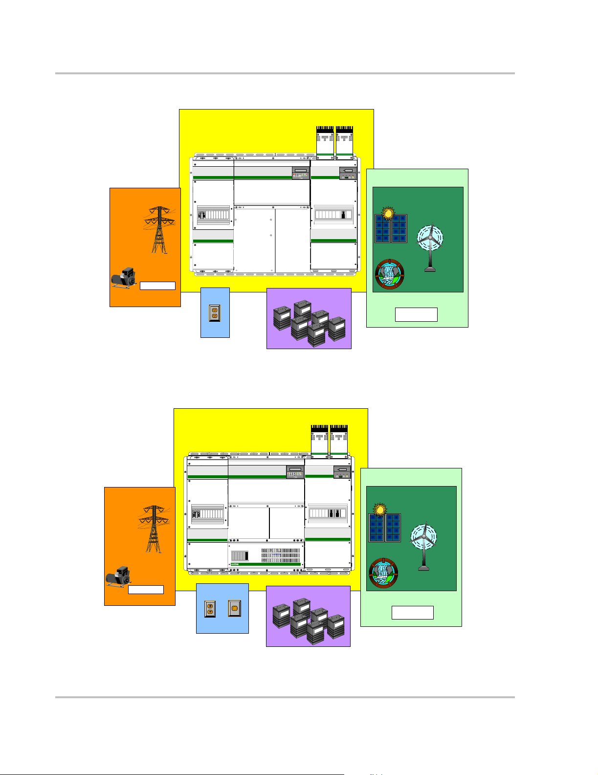
Xantrex Back Plate
AC Input Sources
Sine Wave Plus Power Panel
Multi-Function DC Charge Controll er
Multi-Funct ion DC Charge Controll er
xantrex
xantrex
C-Series
L1 HOT
ACCB-L
DD
GND
NEU
xantrex Sine Wave Plus Inverter / Charger
Inverter Control Module
xantrex
01A Inverter
OFF SRCH ON CHG
GRID TIE
ERRORBULKAC1
INV
GEN
INVERTAC2 FLOATSTATUS
ON/OFF
MENU
SET
MENUMENU HEADINGS
ITEMS
POINTS
DCCB-L
Reset DefaultsContrast
C-Series
BATTERY
LEVEL VOLTS
% v A AH
SELEC
T
Battery Status Meterxantrex
00.0
Ah REMOVED
AMPS
Inverter
RESE
ON/
T
OFF
DC Input Sources
Renewable Energy
Photovoltatic
(PV) Array
June 22, 2004
Figure 1-1
Utility Grid
L2INL1
L1INL2
OUT
OUT
L2INL1
OUTL1INL2OUT
Generator
AC Gene rators
Loads
120 Vac
Loads
Single Inverter Configuration
Sine Wave Plus Power Panel
L1 HOT
ACCB-L
GND
NEU
AC Input Sources
DD
xantrex Sine Wave Plus Inverter / Charger
Energy Storage
Multi-Functi on DC Charge Controll er
xantrex
C-Series
Inverter Control Module
xantrex
01A Inverter
OFF SRCH ON CHG
GRID TIE
ERRORBULKAC1
INV
GEN
INVERTAC2 FLOATSTATUS
ON/OFF
MENU HEADINGSMENU
SET
MENU
ITEMS
POINTS
DCCB-L
Reset DefaultsContrast
Wind
Generator
Hydro
Generator
Multi-Funct ion DC Charg e Contr ol l e r
xantrex
C-Series
Battery Status Meter
xantrex
00.0
BATTERY
Ah REMOVED
LEVEL VOLTS AMPS
AH
% v A
Inverter
RESETSELEC
ON/
T
OFF
DC Input Sources
DC Engine
Generators
Renewable Energ y
Photovoltatic
(PV) Array
Utility Grid
Generator
AC Generators
L2INL1
OUTL1INL2OUT
L2INL1
OUTL1INL2OUT
120 Vac
Loads
Loads
240 Vac
Loads
L
L
N
L1N
1
2
120
240 V
V
TX Autotransformer
Energy Storage
Generator
Hydro
DC Engine
Generators
Wind
Generator
June 22, 2004
Figure 1-2
Single Inverter Configuration with a TX Autotransformer
2 973-0030-01-01 A
Page 3
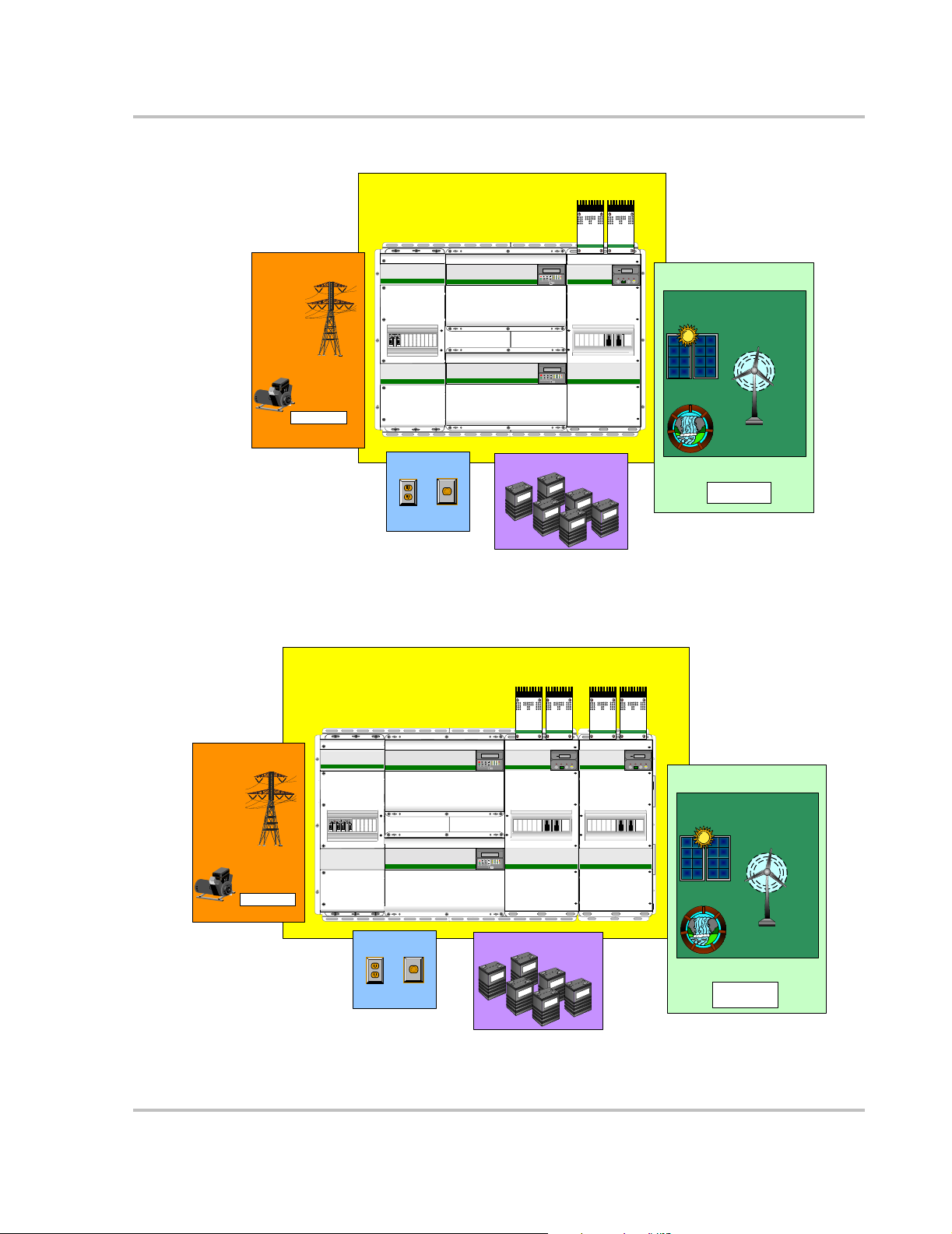
AC Input Sources
Utility Grid
Generator
AC Generators
Installation Instructions
Sine Wave Plus Power Panel
Multi-Functi on DC Charge Controller
Multi-Functi on DC Charge Controll er
xantrex
xantrex
C-Series
L1 HOT
ACCB-L
DD
GND
NEU
L2INL1
OUTL1INL2OUT
L2INL1
OUTL1INL2OUT
xantrex Sine Wave Plus Inverter / Charger
xantrex Sine Wave Plus Inverter / Charger
Inverter Control Module
xantrex
01A Inverter
OFF SRCH ON CHG
GRID TIE
ERRORBULKAC1
INV
GEN
INVERTAC2 FLOATSTATUS
ON/OFF
MENU HEADINGSMENU
SET
MENU
ITEMS
POINTS
Reset DefaultsContrast
Inverter Contr ol Modul e
xantrex
01A Inverter
OFF SRCH ON CHG
GRID TIE
ERRORBULKAC1
INV
GEN
INVERTAC2 FLOATSTATUS
ON/OFF
MENU HEADINGSMENU
SET
MENU
ITEMS
POINTS
Reset DefaultsContrast
C-Series
Battery S tat us Mete r
xantrex
Battery Status Meterxantrex
00.0
00.0
BATTERY
BATTERY
Ah REMOVED
Ah REMOVED
LEVEL VOLTS AMPS
LEVEL VOLTS AMPS
% v A AH
AH
DCCB-L
% v A
T
T
Inverter
RESETSELEC
Inverter
RESETSELEC
ON/OFF
ON/
OFF
DC Input Sources
Renewable Energy
Photovoltatic
(PV) Array
Wind
Generator
Hydro
Figure 1-3
June 22, 2004
Dual Inverter Configuration
AC Input Sources
Utility Grid
Generator
AC Generators
ACCB-L
GND
DD
Energy Storage
Generator
DC Engine
Generators
120 Vac
Loads
Loads
240 Vac
Loads
Sine Wave Plus Power Panel
xantrex
Multi-Functi on DC Charge Contr ol l er
xantrex
Multi-Function DC Charge Controll er
Multi-Functi on DC Charge Control ler
xantrex
xantrex
C-Series
L1 HOT
xantrex
xantrex
Sine W ave Plus Inv er te r / Cha rge r
Sine Wave Plus Inve rter / C harger
NEU
DD
L2INL1
OUTL1INL2OUT
L2INL1
OUTL1INL2OUT
Loads
Inverter Control M odule
xantrex
01A Inverter
OFF SRCH ON CHG
GRID TIE
ERRORBULKAC1
INV
GEN
INVERTAC2 FLOAT STATUS
ON/OFF
MENU
SET
MENU HEADINGS
ITEMS
POINTS
MENU
DCCB-L
Reset DefaultsContrast
Inverter Control Module
xantrex
01A Inverter
OFF SRCH ON CHG
GRID TIE
ERRORBULKAC1
INV
GEN
INVERTAC2 FLOATSTATUS
ON/OFF
MENU HEADINGSMENU
SET
MENU
ITEMS
POINTS
Reset DefaultsContrast
Energy Storage
xantrex
C-Series
BATTERY
LEVEL VOLTS AMPS
% v A
T
Battery Status Meter
00.0
Ah REMOVED
AH
Inverter
RESETSELEC
DCCB-L
ON/
OFF
Multi-Functi on DC Charge Contr ol l er
C-Series
C-Series
Battery Status Meter
xantrex
00.0
BATTERY
Ah REMOVED
LEVEL VOLTS AMPS
% v A
AH
Inverter
RESETSELEC
ON/
T
OFF
DC Input Sources
Renewable Energy
Photovoltatic
(PV) Array
Wind
Generator
Hydro
Generator
DC Engine
Generators
June 22, 2004
Figure 1-4
240 Vac
120 Vac
Loads
Loads
Dual Inverter Configurations with Multiple Renewable Energy
973-0030-01-01 A 3
Page 4
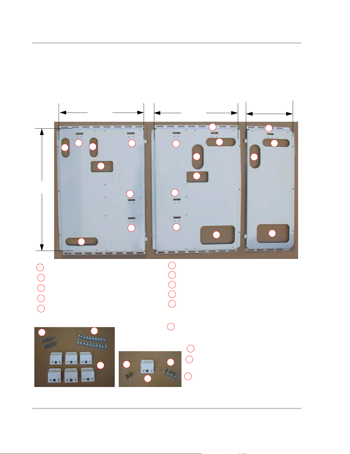
Xantrex Back Plate
Panel Components
The panel is comprised of two plates that fit together and combine to create a solid
support for the power system. If dual DCCB-Ls are to be installed, then an
extension plate (XBP-DC) is available to complete the panel.
23”
(58 cm)
A
B
35”
(89 cm)
A
Mounting hook position for ACCB-L
B
Conduit Pass-thrus for ACCB-L
C
Hand Holds for installing
D
Mounting hook positions for SW Plus Inverter #1
E
Mounting hook positions for SW Plus Inverter #2
B
C
E
XBP
Left Side
B
26”
(58 cm)
G
D
F
D
H
C
E
XBP
Right Side
F
Mounting hook positions for TX Autotransformer
F
Mounting hook position for DCCB-L
G
Conduit Pass-thrus for DCCB-L
H
Mounting Hooks (x6)
I
1/4-20x3/4” phillips screws (x20) for mounting the
J
components (ACCB-L, DCCB-L, SW Plus Inverters,
and TX Autotransformer)
H
H
14”
(36 cm)
G
H
H
XBP-DC
H
10-32x1/2” phillips screws (x12) for the
K
mounting holes
L
M
M
N
Mounting Hook for XBP-DC (x1)
1/4-20x3/4” phillips screws for
XBP-DC (x4)
10-32x1/2” phillips screws for
XBP-DC (x2)
K
Figure 1-5
J
I
N
L
Components of the Xantrex Back Plate (XBP and XBP-DC)
4 973-0030-01-01 A
Page 5

Attaching the Mounting Hooks
To attach the mounting hooks on the panel, following the procedure outlined in
Figure 1-6.
Installation Instructions
1. Place the mounting hook into the hole
provided so that the back of the hook rests
against the panel and the front of the hook
protrudes toward the front.
3. Secure the mounting hooks with the two 1032x½ phillips screws provided.
2. Align the mounting hooks with the predrilled holes in the panel in the positions
required by the components in your
installation.
4. Torque to 32 inch-pounds.
Figure 1-6
Attaching the Mounting Hooks
973-0030-01-01 A 5
Page 6

Xantrex Back Plate
Mounting the Power Panel
These instructions are for light wood-framed structures such as those commonly
found in residential construction. See local building regulations to ensure code
compliance.
Determine total weight
Due to the size and weight of power panel systems, it is extremely important to
consider the strength of the structure to which it will be attached. Use Table 1-1 to
determine the weight of all components intended for installation. At a minimum,
any basic power panel configuration will weigh approximately 270 pounds.
Component
1- XBP Panel (left and right) 54 pounds
1-SW Plus Inverter / Charger 140 pounds
1-ACCB-L 24 pounds
1-DCCB-L 33 pounds
Miscellaneous Hardware/components ~10 pounds
Minimum Weight to Plan For ~270 pounds
Approximate
Weight
CAUTION: Structural Damage
If you are not sure if the wall is strong enough where you want to install the Power Panel
and it’s components, consult a structural engineer for a second opinion and/or
recommendation.
Wallboard is not sufficiently strong to support a Power Panel system. Wall studs
alone are not sufficiently strong enough to support a Power Panel system that
weighs over 300 pounds.
It is recommended that a 3/4-inch sheet of plywood or 3/4-inch APA rated
sheathing be attached directly to the wall studs from the floor to approximately 12
inches above the top of the intended height of the panel. If wall studs are placed at
16" on center, then the 3/4-inch plywood or sheathing must cover at least 3 studs.
If wall studs are placed at 24-inches on center, then the plywood or sheathing
must cover at least 2 studs.
Attach the plywood, or sheathing to the wall studs, using 12d nails to secure the
plywood to the studs every 6 inches.
6 973-0030-01-01 A
Page 7

Installation Instructions
Table 1-1
Component
1-XBP Panel (left and right) 54 lbs (24.5 kg) ACCB-L2-PCK (2nd Bypass Switch) 2 lbs (0.9 kg)
1-XBP-DC Extention 15 lbs (7 kg) C-Series Multi-function DC Controller 3 lbs (1.4 kg) each
1-SW Plus Inverter / Charger 140 lbs (63.5 kg) CC PCK 2 lbs (0.9 kg)
2-SW Plus Inverters / Charger 280 lbs (127 kg) GJ-250-PCK or
1-TX 4K Autotransformer 42 lbs (19 kg) PVGVP-CF-1,
1-TX 6K Autotransformer 60 lbs (27 kg) Battery Status Meter
1-AC Conduit Box - Long
(ACCB-L)
1-AC Conduit Box - Long
(ACCB-L1)
1- DC Conduit Box (DCCB-L) 22 lbs (10 kg) Inverter Control Adapter (ICA) < 1 lbs (0.5 kg)
1- DC Conduit Box (DCCBL175)
Approximate Power Panel Weight for a Given Configuration
Approximate
Weight Accessories
GJ-175-PCK
PVGVP-CF-2 or PVGVP-CF-3
PVGVP-CF-4
(TM500A and TM500A-NS)
19 lbs (9 kg) CF 60 Circuit Breaker < 1 lbs (0.5 kg)
24 lbs (11 kg) Xantrex Battery Cables (BC1.5) Varies up to 40 lbs
33 lbs (15 kg) Inverter Stacking Cable (ISC-S) Series < 1 lbs (0.5 kg)
Approximate
Weight
5 lbs (2.3 kg) each
1 lbs (0.5 kg) ea.
2 lbs (0.9 kg) ea.
3 lbs (1.4 kg) ea.
< 1 lbs (0.5 kg)
(18 kg)
1- DC Conduit Box (DCCBL250)
1-AC Conduit Box (ACCB) 12 lbs (5 kg) Power Distribution Blocks
1-DC Conduit Box (DCCB) 8 lbs (4 kg) DC Negative Bus Bar 2 lbs (0.9 kg)
Weight-bearing or non-weight-bearing wall
It is also important to determine whether the power panel will be mounted on a
load bearing or non-load bearing wall. In general, a load bearing wall is any wall
that carries weight transmitted by other structural members. An example of a load
33 lbs (15 kg) CF Breaker Mounting Plate < 1 lbs (0.5 kg)
< 1 lbs (0.5 kg)
(6:1 and 12:1)
bearing wall is a wall that is carries the weight from an upper floor, a roof, or from
both. A wall that does not carry weight from other structural elements is
considered a non-load bearing wall.
If in doubt contact a licensed structural engineer to help you make the
differentiation.
973-0030-01-01 A 7
Page 8

Xantrex Back Plate
Mounting the Panel to the Wall Studs
To prepare the mounting surface:
1. Determine what height you want the top of the panel to be at.
2. Place a piece of 3/4" plywood from the floor to 12-inches above the desired
height of the panel. If the wall studs are 16" apart, then span the plywood
across three studs. If the wall studs are 24" apart, then span the plywood
across two studs.
3. Secure the panel to the wall studs using 12 (12d) nails (or equivalent) spaced 6 inches apart.
Wall Studs
16" on center
If the wall studs are 16"
apart, then span the
plywood across three
studs.
Wall Studs
24" on center
If the wall studs are
24" apart, then span
the plywood across
two studs.
Floor
Figure 1-7
12 (12d) nails (or equivalent) placed every 6 inches along
stud-line from bottom to top of plywood or sheathing.
Mounting the Plywood
Floor
8 973-0030-01-01 A
Page 9
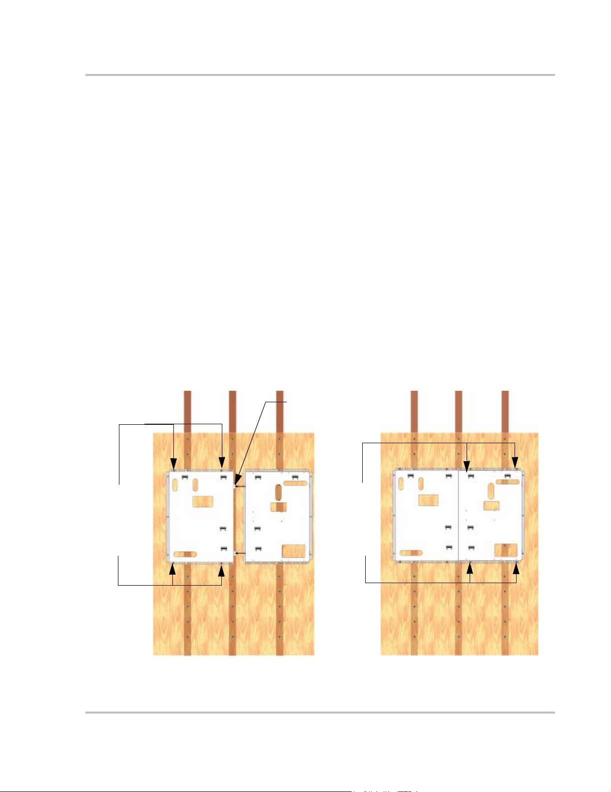
Installation Instructions
To Mount the Back Plate:
1. Lift the XBP-L panel to the plywood. Ensure it’s level.
2. Mark the plywood for a minimum of four pilot holes. Remove the panel.
3. Drill pilot holes through the plywood.
4. Realign the XBP-L over the drilled holes.
5. Insert the minimum four mounting bolts into the pilot holes. More may be used if
desired for additional security. Use ¼" (6mm) or larger fasteners.
6. Tighten securely.
7. Lift the XBP-R into place and slide the mounting tabs on the XBP-R into the
mounting slots on the XBP-L as close as it will go.
8. Mark the wall where the studs are for the supporting screws. Remove the panel.
9. Drill pilot holes through the plywood.
10. Replace the panel and realign the XBP-R over the drilled holes.
11. Insert the minimum four mounting bolts into the pilot holes. More may be used if
desired for additional security. Use ¼" (6mm) or larger fasteners.
12. Tighten securely.
13. Repeat steps 7-12 for the XBP-DC if required.
Secure each
panel to the
plywood with
a minimum of
4 fasteners
Be sure the
1st panel
mounted is
level.
Figure 1-8
XBP-L
Mounting the XBP Back Plate
XBP-R
Insert mounting tabs on
the XBP-L into mounting
slots on edge of XBP-R
Secure each
panel to the
plywood with
a minimum of
4 fasteners
XBP-L
XBP-R
973-0030-01-01 A 9
Page 10

Xantrex Back Plate
Mounting the Components
1. Lift the inverter and place the mounting holes in the rail directly over the mounting
hooks on the panel and lower into place.
2. Install six ¼-20x¾" phillips screws to hold the inverter to the panel, but do not fully
tighten.
3. Lift the second inverter (if used) and place the mounting holes in the rail directly
over the mounting hooks on the panel and lower into place.
4. Install six ¼-20x¾" phillips screws to hold the second inverter to the panel, but do
not fully tighten.
5. Remove the blockoff plates from the ACCB-L and DCCB-L for the components to be installed.
6. Next, lift the other components, such as the ACCB-L and DCCB-L, and place their
mounting hole in the rail directly over the designated mounting hooks on the panel
and lower into place.
Important:
rails. If you can not see the hooks, the unit is not installed properly and will not be secure
to the wall.
Ensure the mounting hooks are visible through the holes in the mounting
7. Tighten the inverter(s) to the panel. Torque to 76 in-lbs.
8. Push the ACCB-L as close to the inverter as it will possibly go and secure it to the
panel using the four of the 20 ¼-20x¾ phillips screws. Torque to 76 in-lbs.
9. Push the DCCB-L as close to the inverter as it will possibly go and secure it to the
panel using the four of the 20 ¼-20x¾ phillips screws. Torque to 76 in-lbs.
Place component mounting hole over mounting hook on panel.
Lower the component so it rests on the mounting hook.
Ensure you can see the
mounting hook in the
top of the component
Secure it to the
panel using 4 of the
1/4-20x3/4" phillips
screws.
Figure 1-9
10 973-0030-01-01 A
Installing the Components on the Backplate
Page 11

Installation Instructions
This completes the installation instructions for the back plate.
Consult Owner’s Guides for all the installed components for wiring instructions.
Trademarks
Xantrex Back Plate is a trademark of Xantrex International. Xantrex is a registered trademark of Xantrex International.
Other trademarks, registered trademarks, and product names are the property of their respective owners and are used herein
for identification purposes only.
Notice of Copyright
Xantrex Back Panel (XBP) Installation Instructions © July 2004 Xantrex International. All rights reserved.
Disclaimer
UNLESS SPECIFICALLY AGREED TO IN WRITING, XANTREX TECHNOLOGY INC. (“XANTREX”)
(a) MAKES NO WARRANTY AS TO THE ACCURACY, SUFFICIENCY OR SUITABILITY OF ANY TECHNICAL OR OTHER
INFORMATION PROVIDED IN ITS MANUALS OR OTHER DOCUMENTATION.
(b) ASSUMES NO RESPONSIBILITY OR LIABILITY FOR LOSS OR DAMAGE, WHETHER DIRECT, INDIRECT,
CONSEQUENTIAL OR INCIDENTAL, WHICH MIGHT ARISE OUT OF THE USE OF SUCH INFORMATION. THE USE OF ANY
SUCH INFORMATION WILL BE ENTIRELY AT THE USER’S RISK.
Date and Revision
July 2004 Revision A
Part Number
973-0030-01-01 A
Contact Information
Telephone: 1 800 670 0707 (toll free North America)
Fax: 1 800 994 7828 (toll free North America)
Email: customerservice@xantrex.com
Web: www.xantrex.com
1 360 925 5097 (direct)
1 360 925 5143 (direct)
973-0030-01-01 A 11
Page 12

12
 Loading...