

Page 1
Xanbus System
Installation Guide
Page 2

Page 3

Xanbus System
Installation Guide
Page 4

About Xantrex
Xantrex Technology Inc. is a world-leading supplier of advanced power electronics and controls with products from
50 watt mobile units to one MW utility-scale systems for wind, solar, batteries, fuel cells, microturbines, and backup
power applications in both grid-connected and stand-alone systems. Xantrex products include inverters, battery
chargers, programmable power supplies, and variable speed drives that convert, supply, control, clean, and distribute
electrical power.
Trademarks
Xantrex and Xanbus are registered trademarks of Xantrex International.
Other trademarks, registered trademarks, and product names are the property of their respective owners and are used
herein for identification purposes only.
Notice of Copyright
Xanbus System Installation Guide © June 2004 Xantrex International. All rights reserved.
Disclaimer
UNLESS SPECIFICALLY AGREED TO IN WRITING, XANTREX TECHNOLOGY INC. (“XANTREX”)
(a) MAKES NO WARRANTY AS TO THE ACCURACY, SUFFICIENCY OR SUITABILITY OF ANY
TECHNICAL OR OTHER INFORMATION PROVIDED IN ITS MANUALS OR OTHER DOCUMENTATION.
(b) ASSUMES NO RESPONSIBILITY OR LIABILITY FOR LOSS OR DAMAGE, WHETHER DIRECT,
INDIRECT, CONSEQUENTIAL OR INCIDENTAL, WHICH MIGHT ARISE OUT OF THE USE OF SUCH
INFORMATION. THE USE OF ANY SUCH INFORMATION WILL BE ENTIRELY AT THE USER’S RISK.
Date and Revision
June 2004 Revision A
Part Number
975-0136-01-01
Contact Information
T e lephone: 1 800 670 0707 (toll free North America)
1 360 925 5097 (direct)
Fax: 1 800 994 7828 (toll free North America)
1 360 925 5143 (direct)
Email: customerservice@xantrex.com
Web: www.xantrex.com
Page 5

About This Guide
Purpose
The purpose of this Guide is to provide explanations and procedures for
planning and installing a Xanbus System.
Scope
The Guide provides planning and setup information and guidelines for
installing the network.
Audience
The Guide is intended f or a nyone who needs to plan for a network and/o r
install a Xanbus System.
975-0136-01-01 iii
Page 6
About This Guide
Conventions Used
The following conventions are used in this guide.
WARNING
Warnings identify conditions or practices that could result in personal injury or
loss of life
CAUTION
Cautions identify conditions or practices that could result in damage to the unit or
other equipment.
Important:
but are not as serious as a caution or warning.
Related Information
Information about additional Xanbus-enabled products is available at
www.xantrex.com.
In order to complete network installation, you will also need to refer to
the Installation, Operation, or Owner’s Guide for the Xanbus-enabled
products you’ve purchased.
Contact Information
Telephone: 1 800 670 0707 (toll free North America)
Fax: 1 800 994 7828 (toll free North America)
Email: customerservice@xantrex.com
Web: www.xantrex.com
These notes describe things that are important for you to know,
1 360 925 5097 (direct)
1 360 925 5143 (direct)
iv 975-0136-01-01
Page 7

Contents
Installation
Xanbus-enabled Devices- - - - - - - - - - - - - - - - - - - - - - - - - - - - - - - - - - - - - - - - - - - - - - - - - - - -2
RS2000 Sine Wave Inverter/Charger - - - - - - - - - - - - - - - - - - - - - - - - - - - - - - - - - - - - - - - - -2
System Control Panel - - - - - - - - - - - - - - - - - - - - - - - - - - - - - - - - - - - - - - - - - - - - - - - - - - -2
The Xanbus System - - - - - - - - - - - - - - - - - - - - - - - - - - - - - - - - - - - - - - - - - - - - - - - - - - - - - - -3
Purchasing System Accessories- - - - - - - - - - - - - - - - - - - - - - - - - - - - - - - - - - - - - - - - - - - - -4
Purchasing Network Components - - - - - - - - - - - - - - - - - - - - - - - - - - - - - - - - - - - - - - - - - - -4
Planning the Network- - - - - - - - - - - - - - - - - - - - - - - - - - - - - - - - - - - - - - - - - - - - - - - - - - - - - -5
Network Layouts - - - - - - - - - - - - - - - - - - - - - - - - - - - - - - - - - - - - - - - - - - - - - - - - - - - - - -5
Multi-Drop Backbone Layout - - - - - - - - - - - - - - - - - - - - - - - - - - - - - - - - - - - - - - - - - - -5
Daisy Chain Layout - - - - - - - - - - - - - - - - - - - - - - - - - - - - - - - - - - - - - - - - - - - - - - - - -6
Network Connectors, Terminators, and Cables - - - - - - - - - - - - - - - - - - - - - - - - - - - - - - - - - -7
Cabling Re quirements - - - - - - - - - - - - - - - - - - - - - - - - - - - - - - - - - - - - - - - - - - - - - - - -8
Connector Requirements - - - - - - - - - - - - - - - - - - - - - - - - - - - - - - - - - - - - - - - - - - - - - -9
Network Power Supply - - - - - - - - - - - - - - - - - - - - - - - - - - - - - - - - - - - - - - - - - - - - - - - - - -9
Network Size - - - - - - - - - - - - - - - - - - - - - - - - - - - - - - - - - - - - - - - - - - - - - - - - - - - - - - - -10
Installing the Network - - - - - - - - - - - - - - - - - - - - - - - - - - - - - - - - - - - - - - - - - - - - - - - - - - - - 11
Before You Begin the Installation - - - - - - - - - - - - - - - - - - - - - - - - - - - - - - - - - - - - - - - - - - 11
Installation Tools and Materials- - - - - - - - - - - - - - - - - - - - - - - - - - - - - - - - - - - - - - - - - - - - 11
Guidelines for Routing the Network Ca bles- - - - - - - - - - - - - - - - - - - - - - - - - - - - - - - - - - - - 12
Mounting a Network Connector - - - - - - - - - - - - - - - - - - - - - - - - - - - - - - - - - - - - - - - - - - - 13
Installing Xanbus-enabled Devices - - - - - - - - - - - - - - - - - - - - - - - - - - - - - - - - - - - - - - - - -13
Connecting Your Xanbu s System - - - - - - - - - - - - - - - - - - - - - - - - - - - - - - - - - - - - - - - - - - 1 4
Completing the Multi-Drop Backbone Layout - - - - - - - - - - - - - - - - - - - - - - - - - - - - - - -14
Completing the Daisy Chain Layout - - - - - - - - - - - - - - - - - - - - - - - - - - - - - - - - - - - - - 15
Putting the System in Safe Mode - - - - - - - - - - - - - - - - - - - - - - - - - - - - - - - - - - - - - - - - - - - 16
Testing You r Installation - - - - - - - - - - - - - - - - - - - - - - - - - - - - - - - - - - - - - - - - - - - - - - - - - -18
Verifying P ower is Available - - - - - - - - - - - - - - - - - - - - - - - - - - - - - - - - - - - - - - - - - - - - - 18
Verifying Network Communications - - - - - - - - - - - - - - - - - - - - - - - - - - - - - - - - - - - - - - - - 1 8
System Modes - - - - - - - - - - - - - - - - - - - - - - - - - - - - - - - - - - - - - - - - - - - - - - - - - - - - - - - - - 20
Operate mode - - - - - - - - - - - - - - - - - - - - - - - - - - - - - - - - - - - - - - - - - - - - - - - - - - - - - - - - 2 1
Safe Mode - - - - - - - - - - - - - - - - - - - - - - - - - - - - - - - - - - - - - - - - - - - - - - - - - - - - - - - - - -21
Power Save mode - - - - - - - - - - - - - - - - - - - - - - - - - - - - - - - - - - - - - - - - - - - - - - - - - - - - - 21
Hibernate m ode - - - - - - - - - - - - - - - - - - - - - - - - - - - - - - - - - - - - - - - - - - - - - - - - - - - - - - 22
975-0136-01-01 v
Page 8

vi
Page 9

Figures
Figure 1 Example of Multi-Drop Backbone - - - - - - - - - - - - - - - - - - - - - - - - - - - - - - - - - - - - - - -3
Figure 2 Multi-Drop Backbone Layout - - - - - - - - - - - - - - - - - - - - - - - - - - - - - - - - - - - - - - - - - -5
Figure 3 Daisy Chain Layout- - - - - - - - - - - - - - - - - - - - - - - - - - - - - - - - - - - - - - - - - - - - - - - - -6
Figure 4 3-Way Network C onnector (sa mple config uration)- - - - - - - - - - - - - - - - - - - - - - - - - - - -7
Figure 5 Network Termi nators- - - - - - - - - - - - - - - - - - - - - - - - - - - - - - - - - - - - - - - - - - - - - - - -8
Figure 6 RJ4 5 Connector - - - - - - - - - - - - - - - - - - - - - - - - - - - - - - - - - - - - - - - - - - - - - - - - - - -9
Figure 7 Recommended Mounting Orientation for Network Connector - - - - - - - - - - - - - - - - - - -13
Figure 8 Options for Completing a Multi-Drop Backbone Layout - - - - - - - - - - - - - - - - - - - - - - -14
Figure 9 Completing a D aisy-Chain Layout - - - - - - - - - - - - - - - - - - - - - - - - - - - - - - - - - - - - - -15
Figure 10 Select Devic e Menu- - - - - - - - - - - - - - - - - - - - - - - - - - - - - - - - - - - - - - - - - - - - - - - - 16
Figure 11 System Sett ings Menu - - - - - - - - - - - - - - - - - - - - - - - - - - - - - - - - - - - - - - - - - - - - - - 16
Figure 12 Safe Mode - - - - - - - - - - - - - - - - - - - - - - - - - - - - - - - - - - - - - - - - - - - - - - - - - - - - - - 17
Figure 13 System Home Screen- - - - - - - - - - - - - - - - - - - - - - - - - - - - - - - - - - - - - - - - - - - - - - - 1 8
Figure 14 System Sett ings: View Device Info - - - - - - - - - - - - - - - - - - - - - - - - - - - - - - - - - - - - - 19
Figure 15 Device Information Screen (RS2000 used for example)- - - - - - - - - - - - - - - - - - - - - - - -19
Figure 16 System Control Panel - - - - - - - - - - - - - - - - - - - - - - - - - - - - - - - - - - - - - - - - - - - - - - 20
Figure 17 Operate Mo de- - - - - - - - - - - - - - - - - - - - - - - - - - - - - - - - - - - - - - - - - - - - - - - - - - - - 21
Figure 18 Entering Po wer Save Mode- - - - - - - - - - - - - - - - - - - - - - - - - - - - - - - - - - - - - - - - - - -22
Figure 19 Hibernate Mo de - - - - - - - - - - - - - - - - - - - - - - - - - - - - - - - - - - - - - - - - - - - - - - - - - - 22
CAUTION: Equipment damage
:
975-0136-01-01 vii
Connect the Xanbus System only to Xanbus compatible devices.
Although the cabling and connectors used in this network system are the same as
Ethernet connectors, this network is not an Ethernet system. Equipment
damage may result from attempting to connect these two different systems.
Page 10

viii
Page 11

Installation
The Installation Guide provides detailed information for
planning and installing a Xanbus System.
Page 12

Installation
Xanbus-enabled Devices
The Xanbus™-enabled designation means that this product works on a
Xanbus network. Xanbus-enabled products are:
• Easy to use. The Xanbus network simplifies operation and automates
routine tasks.
• Reliable. Software control eliminates errors due to analog signalling.
• Accurate. Digital information is less susceptible to interference and
line loss.
• Upgradeable. Firmware upgr ades me an your pur chase wil l remain up
to date.
More Xanbus-enabled devices will become available in the future.
RS2000 Sine Wave Inverter/Charger
The RS2000 Sine Wave Inverter/Charger is a convenient combination of
an inverter, multistage battery charger, and transfer switch in one
electronic device. It is also the device that typically powers the Xanbus
system. For complete information, see the RS2000 Sine Wave Inverter/
Charger Operation Guide and RS2000 Sine Wave Inverter/Charger
Installati on Guide.
System Control Panel
The System Control Panel provides configuration and monitoring
capability for Xanbus-enabl ed devic es. For complete inf ormati on, see the
user guide for your interface panel.
For detailed instructions and a complete list of Xanbus-enabled devices,
visit the website at www.xantrex.com.
2 975-0136-01-01
Page 13

Installation
The Xanbus System
What is a network? A network is a colle ction of devices that perfo rm individ ual functio ns, but
also communicate and interact with the other devices. The Xanbus
System provides a robust, integrated product solution which simplifies
and automates the installation, configuration, control, monitoring, and
integration of devices that deliver and distribute AC or DC power.
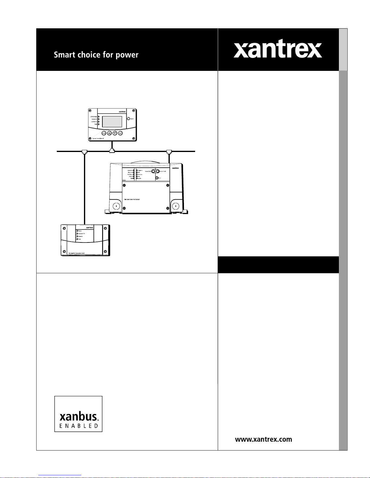
Components of a
network
Components of a network incl ude the device s such a s an inve rter /charger,
a control panel, and an automatic generator start. These devices are
integrated into a network using cables, network connectors, and
terminators. An example of a power network is shown in Figure 1.
3-way network
connector
Interface panel
Network
cable
Xanbus-enabled inverter/charger
Automatic Generator Start
Figure 1
Network
configurations
975-0136-01-01 3
The network can be installed in one of two configurations: as a multi-drop
backbone (see Figure 1 and Figure 2) or as a daisy chain (see Figure 3).
Example of Multi-Drop Backbo ne
Page 14

Installation
Purchasing System Accessories
System accessories are avai lable fr om any author ized Xant rex deale r or at
www.xantrex.com. Table 1 provides a partial list of system accessories.
When ordering, please provide the part number of the accessory to the
dealer.
Table 1
Accessory Dimensions H x W x D Part number
System Control Panel (SCP) 4.0 × 6 × 1.60 inches
Automatic Generator Starter
(AGS)
System Accessories
Purchasing Network Components
Consult with your local system designer to determine what network
components will be needed for your specif ic installa tion. Table 2 provides
a partial list of network components and part numbers. Pre-made cables
are available in standard lengths from 3 feet to 75 feet.
For the most up-to-date list, call your dealer. Call your dealer or visit
www.xantrex.com to purchase cables and other network components.
Table 2
Network Component Part Number
Network termination — Male (2 per pack) 809-0901
Network termination — Female (2 per pack) 809-0905
3-way network connector 809-0903
Network cable 3 ft. (0.9 m) 809-0935
Network cable 5 feet (1.5 m) 809-0936
Network cable 7 feet (2.0 m) 809-0937
Network cable 10 feet (3.0 m) 809-0938
Network cable 14 feet (4.3 m) 809-0939
Network cable 25 feet (7.6 m) 809-0940
Network cable 50 feet (15.2 m) 809-0941
Network cable 75 feet (22.9 m) 809-0942
Network Components and Part Numbers
(101 × 152 × 41 mm)
3.8 × 5.8 × 1. 5 inches
(97 × 147 × 38 mm)
809-0910
809-0915
4 975-0136-01-01
Page 15

Planning the Network
This section provides information on the following topics:
• two types of network layouts and the advantages and disadvantages
of each layout
• network components
• network connectors and/or terminators
• cable and connector requirements of each layout
• network power supply and network size
See “Installing the Network” on page 11 for instructions on routing and
layout.
Network Layouts
Xanbus-enabled devices can be connected in one of two Xanbus System
layouts: the multi- dro p backbone or the daisy chain . Eac h net w or k la yout
has advantages and disadvantages, depending on the application and/or
environment. It is up to you or your system designer to decide which
layout is be st for your installation.
Installation
Important:
configurations are not supported by Xantrex.
Multi-Drop Backbone Layout
In a multi-drop backbone layout, each Xanbus-enabled device on the
network is connected by a drop cabl e to the network bus or backbone with
a network connector, as shown in Figure 2.
Figure 2
Do not mix the two types of network layouts. Mixed
Xanbus-enabled
Device 1
Network
connector
Drop cable
Xanbus-enabled
Device 3
Xanbus-enabled
Device 2
Multi-Drop Backbone Layout
Network
backbone cable
TerminatorTerminator
975-0136-01-01 5
Page 16

Installation
Terminators Terminators are required at both ends of the multi-drop backbone cable,
as shown in Figure 2. Therefore, the Xanbus-enabled devices do not
require their own termi nation. W ith o nly one terminat or , the signal quality
is degraded and performance on the network is reduced. Permanent
configuration with only one terminator is not supported by Xantrex.
If cables are placed at the end of the network (as in Figure 2), female
terminators are required. Otherwise, male terminators can be inserted
directly into the open jack of each network connector at the end of the
network.
Advantages The multi-drop backbone layout is reliable and robust and is
recommended for OEM installations.
In this layout, Xanbus-enab led devi ces can be re moved or replaced while
still keeping the netw ork operating.
Disadvantage The main disadvantage of this layout is cost. The network connectors are
more expensive than in a daisy chain layout (which uses no network
connectors), and each device in this layout requires its own network
connector.
Daisy Chain Layout
In a daisy chain lay out, each d evice on the netw ork is l inked with separat e
lengths of cable, as shown in Figure 3. This layout does not require
network connectors.
Xanbus-enabled
Device 1
Terminator
Figure 3
Daisy Chain Layout
Xanbus-enabled
Device 2
Xanbus-enabled
Device 3
Terminator
Terminators As in the multi-drop backbone layout, two terminators are required to
ensure the communication signal quality on the network. The Xanbusenabled devices at each end of the chain must have a male terminator
inserted into their open network ports, as shown in Figure 3.
Advantage The advantage of this layout is that it is less expensive to install because
network connectors are not required.
6 975-0136-01-01
Page 17

Installation
Disadvantage The disadvantage of the daisy chain layout is that Xanbus-enabled
devices cannot be removed from the network without interrupting the
network. T o make t he network funct ion after re moving a device, you mus t
connect the Xanbus-enabled devices on either side of the missing device
to each other or replace the device.
Network Connectors, Terminators, and Cables
CAUTION: Equipment Damage
Connect only to other Xanbus-compatible devices.
Although the cabling and connectors used in this network system are the same as
ethernet connectors, this network is not an ethernet system. Equipment
damage may result from attempting to connect Xanbus to different systems.
Network connectors, terminators, and cables are used to build your
Xanbus network.
3-way network
connector
The 3-way connector houses three RJ45 jacks that provide a device
connection point on a multi-drop layout. All three jacks are wired
identically and can accept either network cables or terminators. One jack
is available for connecting to a Xanbus-enabled device. The remaining
jacks are reserved for connection to two other network connectors, a
terminated network cable, or a male terminator.
The network connector is mounted to a bulkhead or a wall, as shown in
Figure 4.
To network connector
or teminator
To device
To network connector
Figure 4
975-0136-01-01 7
3-Way Network Connector (sample configuration )
Page 18

Installation
Terminators Terminators are required at both ends of the network to ensure the
communication signal quali ty on the network . The t ermina tors ar e female
and male. See Figure 5.
The terminator requirements are different for each layout. See Figure 8
and Figure 9.
Male terminator
Figure 5
Female terminator
Network Terminators
Cabling Requirements
CAUTION: Equipment damage
Do not use crossover cable in a Xanbus System.
Cabling The network uses Category 5 (CAT 5) cable, a standard cable available
from Xantrex or any computer supply store. The cable consists of eight
conductors in fou r twis ted pa irs wit h an RJ45 modular connec tor wi red t o
the T568A standard. Table 3 contains the arrangements of wire colors to
pin numbers for the T568A standard.
Table 3
Pin Number Conductor Name CAT 5 Cable Insulati on Color
T568A Standard Wiring
1 NET_S White/Green
2 NET_S Green
3 NET_C White/Orange
4 CAN_L Blue
5 CAN_H White/Blue
6 NET_C Orange
7 NET_S White/Brown
8 NET_C Brown
8 975-0136-01-01
Page 19

Installation
Connector Requirements
Different types of connectors are required to install the Xanbus-enabled
devices on the network cable.
RJ45 connector The network cable uses modular RJ45 connectors, as shown in Figure 6.
The connector is suitable for cost-sensitive applications and is easily
installed by an e nd user. The RJ45 connector should be a modular plug, 8position, 8-contact for round, stranded, unshielded cable.
Figure 6
RJ45 Connector
Network Power Supply
In a Xanbus System, t he power sources must provide s ufficient power for
all of the Xanbus-enabled devices.
Important:
network. Typically, this is your inverter/charger.
Power supply The network must have at leas t one devi ce with a powe r supply to run the
network. The total network current supplied by all the power-sourcing
devices must be greater than or equal to the total current drawn by the
power consuming devices.
For example, in a system with an inverter/charger, an interface panel and
an Automatic Generator Start, the inverter/charger is a power-sourcing
device capable of providing 800 mA at 15 VDC while the two other
devices each consume a maximum of 200 mA for a total maximum
consumption of 400 mA. In this example, the network is properly
configured from a p ower per spect ive be cause t he power s ource i s capa ble
of providing more current than is needed: 800 mA ≥ 400 mA.
Note: See your Xanbus device guides to determine how much power each
device consumes or supplies.
All networks, regardless of type, require a device that powers the
975-0136-01-01 9
Page 20

Installation
Network Size
Table 4 summarizes the network size in terms of distances and cable
lengths.
Table 4
Cable Length Minimum Maximum
Backbone or daisy chain 4 inches (10 cm) 130 feet (40 meters)
Total backbone length or daisy chain 4 inches (10 cm) 130 feet (40 meters)
Drop cable on backbone 4 inches (10 cm) 10 feet (6 meters)
Minimum and Maximum Cable Length
10 975-0136-01-01
Page 21

Installing the Network
Installation
Important:
configurations are not supported by Xantrex.
Important:
system must be performed with the Xanbus System in Safe mode. See “Putting
the System in Safe Mode” on page 16.
Do not mix the two types of network layouts. Mixed
Installing and replacing Xanbus-enabled devices in an existing
Before You Begin the Installation
• Read the entire section before installing the network. It’s important to
plan your installation from beginning to end.
• Assemble all the tools and materials you require for the installation.
Installation Tools and Materials
Tools You will need the following tools to install the network cables.
❐ Phillips screwdriver, appropriately sized
❐ Drill and 1/8" bit
Materials You will need the following materials to complete your installation.
❐ CAT 5 cables (available from Xantrex or computer supply stores)
❐ Network connectors, if installing multi-drop backbone layout
❐ # 6 screws, 2 per each network connector installed
❐ Terminators
975-0136-01-01 11
Page 22

Installation
Guidelines for Routing the Network Cables
WARNING: Shock hazard
:
Do not route the network cables in the same conduit or panel as the AC and DC
power cabling.
To ensure maximum performance of your network, follow these
guidelines when routing the network cables. Route the cables before
installing Xanbus-enabled devices.
• Route the cables away from sharp edges that might damage the
insulation. Avoid sharp bends in the cable—no less than a 4-inch
radius.
• Allow for some slack in the cable tension. Cable tension should not
exceed 25 lbs.
• Keep the alignment of wire pairs inside the sheath as straight as
possible.
• Allow separation between data and power cables (data cables should
only cross a power cable at right angles).
• Do not staple the cable with metal cable staples. Use the appropriate
hardware fasteners to avoid damage to the cable.
• Apply cable ties loosely.
• Support horizontal cables using J hooks or cable trays.
12 975-0136-01-01
Page 23

Mounting a Network Connector
To mount a network connector:
1. Select an appropri ate locatio n with the connec tor in the re commended
mounting orientation, as shown in Figure 7.
Installation
Figure 7
2. Mark the position of the mounting screws.
3. Pilot drill the two mounting holes.
4. Fasten the network connector to the mounting surface with two #6
Recommended Mounting Orientation for Network Connector
screws.
Installing Xanbus-enabled Devices
If you are installing a Xanbus-enabled device on an existing Xanbus
System, see “Putting the System in Safe Mode” on page 16.
Important:
To install the Xanbus-enabled devices:
1. Determine and prepare the location for each device. Refer to the
installation procedure in the appropriate guide. See “Related
Information” on page iv.
2. Measure and determine the required cable length, taking into
consideration the routing and strain relief requirements.
Do not exceed the total recommended cable length of 130 feet (40
meters).
Mount cables and network connectors in a dry location.
3. Mount the devices according to the installation procedure in the
appropriate guide.
4. Connect to the network.
975-0136-01-01 13
Page 24

Installation
Connecting Your Xanbus System
Use an appropriate length of network cable to connect each device and 3way network connector (if used). See Figure 2 on page 1–5 and Figure 3
on page 1–6.
CAUTION: Equipment Damage
Connect only to other Xanbus compatible devices.
Although the cabling and connectors used in this network system are the same as
ethernet connectors, this network is not an ethernet system. Equipment
damage may result from attempting to connect Xanbus to different systems.
Completing the Multi-Drop Backbone Layout
To complete the multi-drop backbone layout:
◆ Attach a female terminator to the backbone cable at each end of the
network
Or
◆ Insert a male terminator into the open jack of the network connector
at each end of the network (see Figure 8).
Attach female terminator to
end of backbone cable.
To device
To previous
connector
Insert male terminator into
open jack of connector.
Figure 8
14 975-0136-01-01
Options for Completing a Multi-Drop Backbone Layout
Page 25

Completing the Daisy Chain Layout
To complete the daisy chain layout:
◆ Insert male terminators into the open network ports of the Xanbus-
enabled devices at each end of the network. See Figure 9.
Installation
Figure 9
Completing a Daisy-Chain Layout
CAUTION: Unpredictable devi ce behavior
After connecting the Xanbus-enabled devices and terminating the network, do
not plug terminators or other cables into any remaining open network ports on
any Xanbus-enabled devices.
Do not connect one end of the network to the other to make a ring.
975-0136-01-01 15
Page 26

Installation
Putting the System in Safe Mode
CAUTION: Unpredictable device behavior
Before removing or installing a device on an existing Xanbus System, you must
put the system into Safe mode from the System Control Panel.
In Safe mode, all Xanbus-enabled devices remain powered and continue
to communicate, and all device outputs are disabled.
To enter Safe mode:
1. On the Select Device menu, use the down arrow button to highlight
System, as shown in Figure 10.
The cursor on the right of the screen indicates where you are in the
menu.
Figure 10
Select Device Menu
2. Press Enter.
The System Settings menu appears.
Figure 11
System Settings Menu
3. On the System Settings menu, with Desired Mode highlighted, as
shown in Figure 11, press Enter.
4. Use the down arrow button to scrol l through the other modes to sele ct
Safe mode, as shown in Figure 12.
16 975-0136-01-01
Page 27

Installation
For more information on the different system modes (Operat e, Power
Save, and Hibernate), see “System Modes” on page 20.
Figure 12
Safe Mode
5. Press Enter.
You are now in Safe mode.
6. Press Exit twice to return to the System Home screen.
To exit Safe mode:
1. On the System settings menu, with Desired Mode highlighted, press
Enter.
2. Use the down arrow button to select your desired system mode.
3. Press Enter.
975-0136-01-01 17
Page 28

Installation
Testing Your Installation
After you have installed the Xanbus System, you should confirm that
your installation is operating correctly.
Verifying Power is Available
Each Xanbus-enabled device has an indicator light or display screen that
confirms that it is rece ivi ng powe r. See the Installation or Owner’s Guide
for each Xanbus-enabled device for information on verifying network
power.
Verifying Ne t w o rk Communications
You can confirm that a Xanbus-enabled device is properly installed and
communicating on the network by vie wing its firmware revision number.
The firmware revision number is available on the System Control Panel
Device Inf ormation screen.
To view the firmware version for a device:
1. On the System Home screen, press Enter
You can identify the System Home screen by the down-pointing
“menu” arrow on the bottom left corner of the screen. See Figure 13.
18 975-0136-01-01
menu
Figure 13
2. On the Select Device menu, use the down arrow button to highlight
System.
3. Press Enter.
4. On the System Settings menu, use the d own a rrow butt on to h ighli ght
View Device Info, as shown in Figure 14.
System Home Screen
Page 29

Installation
Figure 14
5. Press Enter.
6. To view the Device Information screen for each device, press the
down arrow button.
System Settings: View Device Info
809-2000
442-0110-01-01
1.00.00
Figure 15
7. To return to the System Settings menu, press Exit .
Device Information Screen (RS2000 used for example)
975-0136-01-01 19
Page 30

Installation
System Modes
This section provide s a brief overview of the fou r dif ferent system modes .
See the System Control Panel Owner’s Guide for complete information.
The system modes described in this section affect the performance and
behavior of all Xanbus-enabled devices on the Xanbus System.
You can change system modes using the System Settings menu on the
System Control Panel.
You can also use the red System button on the System Control Panel to
put the System Control Panel and all other Xanbus-enabled devices into
Power Save mode only, as shown in Figure 16.
red
System
button
Figure 16
System Control Panel
System modes are changed using the System Settings menu. The four
system modes are:
•Operate
•Safe
• Power Save
• Hibernate
20 975-0136-01-01
Page 31

Installation
Operate mode
Characteristics In Operate mode, all c ommuni cat ions are enabled on the Xanbu s Sy st em.
All power conversion functions are enabled. Each device is monitoring
and communicating its input.
The default mode of any Xanbus-enabled device is Operate mode.
Whenever any device on the Xanbus System is powered on or reset, it
will be in Operate Mode, as shown in Figure 17.
Figure 17
Operate Mode
Safe Mode
See “Putting the System in Safe Mode” on page 16 for more information.
Power Save mode
Characteristics Power Save mode minimizes power drawn by the Xanbus-enabled
devices. Power Save mode stops all communication on the network,
putting the system to “sleep” until it receives a command to “wake up”
again.
When to use Use Power Save mode during periods when your power needs are
minimal—while you are driving, for example. Putting the system in
Power Save mode will help preserve the charge in your batteries during
periods of minimal power usage.
Entering and exiting Power Save mode also ser ves as a reset c ommand for
the system.
To enter or exit Power Sa ve mode:
◆ Press and hold t he r ed Syst em but ton on the System Control Panel for
at least one second.
When the system enters Power Save mode, the screen on the System
Control Panel goes blank and the backlight turns off.
You can also enter Power Save mode on the System Settings menu by
selecting Desired Mode, scrolling to PowerSave as shown in Figure 18,
and pressing Enter.
975-0136-01-01 21
Page 32

Installation
Returning to
Operate mode
Figure 18
If an inverter/charger supplies power to the network, you can bring the
system out of Power Sav e mode by app lying AC input (wit h utilit y power
Entering Power Save Mode
or generator power) or by pressing the Reset button on the inverter/
charger.
Hibernate mode
Characteristics Hibernate mode removes power from all Xanbus-enabled devices on the
Xanbus System. All operations are suspended until power is restored to
the networ k.
When to use
Important:
Hibernate mode when leaving your system unattended for extended periods of
time.
If there are active faults in the system, you cannot put the system into
Hibernate mode. Clear a ny active faults, correct t he condition that cause d
the fault, then put the system into Hibernate mode, as sh own in Figure 19.
To prevent any system activity, put the Xanbus system into
22 975-0136-01-01
Figure 19
Operate
Hibernate Mode
Page 33

Installation
Restoring power Once in Hibernate mode, the system cannot return to Operate mode by
itself. You must restore power to the network manually.
If an inverter/charger supplies power to the network, you can bring the
system out of Hibernate mode by app lying qualifi ed AC input power wi th
utility power or generator power.
For more information on the behavior of specific Xanbus-enabled
devices, refer to Operation Guide or Owner’s Guide for each device.
975-0136-01-01 23
Page 34

24
Page 35

Page 36

Xantrex Technology Inc.
1 800 670 0707 Tel toll free NA
1 360 925 5097 Tel direct
1 800 994 7828 Fax toll free NA
1 360 925 5143 Fax direct
customerservice@xantrex.com
www.xantrex.com
975-0136-01-01
 Loading...