

Page 1
Voyager Series
Inverter / Charger
Owner’s Manual
2000 Trace Engineering P/N 975-0006-01-01 Rev. A 3/00
Page 2

Voyager Series
inside front cover
2000 Trace Engineering
Page 3

Voyager Series
IMPORTANT SAFETY INSTRUCTIONS
This manual contains important safety and operating instructions that should be followed during the
installation, operation and maintenance of this product as prescribed by UL for inverters used in marine
applications.
To reduce the risk of electrical shock, and to ensure the safe installation and operation of this product,
the following safety symbols have been placed throughout this manual to indicate dangerous conditions
and important safety instructions.
WARNING - A dangerous voltage or condition exists in this area.
Use extreme caution when performing these tasks.
AVERTISSEMENT - Une tension ou condition dangereuse existe dans cette zone.
Faire preuve d’extrême prudence lors de la réalisation de ces tâches.
CAUTION - This procedure is critical to the safe installation or
operation of the unit. Follow these instructions closely.
ATTENTION - Cette procédure est essentielle à l’installation ou l’utilisation
de l’unité en toute sécurité. Suivre ces instructions de près.
NOTE - This statement is important. Follow instructions closely.
NOTE - Cette déclaration est importante. Suivre les instructions de près.
• All electrical work must be done in accordance with local, national, and/or international electrical codes.
• Before installing or using this device, read all instructions and cautionary markings located in the
operator’s manual.
• Do not expose this unit to rain, snow or liquids of any type. This product is designed only for indoor
mounting.
• To reduce the chance of short-circuits when installing or working with the inverter or the batteries, use
insulated tools.
• Remove all jewelry such as rings, bracelets, necklaces, etc., while installing this system. This will
greatly reduce the chance of accidental exposure to live circuits.
• The inverter contains more than one live circuit (batteries and AC line). Power may be present at
more than one source.
• This product contains no user serviceable parts. Do not attempt to repair this unit unless fully qualified.
2000 Trace Engineering
SAVE THESE INSTRUCTIONS
i
Page 4

Voyager Series
BATTERY SAFETY INFORMATION
• Always wear eye protection, such as safety glasses, when working with batteries.
• Remove all loose jewelry before working with batteries.
• Never work alone. Have someone assist you with the installation or be close enough to come to your
aid when working with batteries.
• Always use proper lifting techniques when handling batteries.
• Always use identical types of batteries.
• Never install old or untested batteries. Check each battery’s date code or label to ensure age and type.
• Batteries are temperature sensitive. For optimum performance, they should be installed in a stable
temperature environment.
• Batteries should be installed in a well vented area to prevent the possible build-up of explosive gasses.
If the batteries are installed inside an enclosure, vent its highest point to the outdoors.
• When installing batteries, allow at least 1 inch of air space between batteries to promote cooling and
ventilation.
• Never smoke in the vicinity of a battery or generator.
• Always connect the batteries first, then connect the cables to the inverter. This will greatly reduce the
chance of spark in the vicinity of the batteries.
• Use insulated tools when working with batteries.
• When connecting batteries, always verify proper voltage and polarity.
• Do not short-circuit battery cables. Fire or explosion can occur.
• In the event the skin is exposure to battery electrolyte, wash the area with soap and water. If acid
enters the eyes, flood them with running cold water for at least 15 minutes and get immediate medical
attention.
• Always recycle old batteries. Contact the local recycling center for proper disposal information.
SAVE THESE INSTRUCTIONS
ii
2000 Trace Engineering
Page 5

Voyager Series
Voyager Series Owner’s Manual
Table of Contents
Section Description Page
1 Introduction 1
1.1 Features and Benefits 1
1.2 Standard Features 1
1.3 Optional Features 1
1.4 How an Inverter Works 3
1.5 What an Inverter Can Power 3
1.6 A Quick Tour 5
2. Installation 6
2.1 Unpacking and Inspection 6
2.2 Pre-Installation 6
2.2.1 Locating the Inverter 6
2.2.2 Locating the Batteries 6
2.2.3 Battery Selection 7
2.2.3.1 Flooded Lead Acid Batteries (LEAD) 7
2.2.3.2 Sealed Batteries (GEL and AGM) 7
2.2.4 Tools Required 8
2.2.5 Hardware / Materials Required 8
2.2.6 Wiring 8
2.2.6.1 AC Connections 8
2.2.6.2 DC Connections 8
2.2.6.3 AC Grounding 8
2.2.6.4 DC Grounding 9
2.2.7 Torque Requirements 9
2.2.8 Main Service Panel 9
2.2.9 Sub Panel 9
2.2.10 Circuit Protection 9
2.2.11 Wire Routing 9
2.3 Installation 11
2.3.1 Inverter Mounting 13
2.3.2 Battery Mounting 13
2.3.3 Battery Cables and Sizing 13
2.3.4 DC Wiring 15
2.3.5 Battery Wiring 15
2.3.5.1 Parallel Connection 17
2.3.5.2 Series Connection 17
2.3.5.3 Series / Parallel Connection 19
2.3.6 DC Fuse Block (or Circuit Breaker) Installation and Wiring 19
2.3.7 AC Wiring 21
2.3.7.1 Inverter AC Input 23
2.3.7.2 Inverter AC Output 23
2.3.7.3 Final Inspection 23
2.3.8 Neutral to Ground Bonding 25
2.4 Options 27
2.4.1 Battery Temperature Sensor (BTS) Installation and Wiring 27
2.4.2 RC8 Installation and Wiring 27
2.4.3 Remote (RC5 and URC) Installation and Wiring 27
2.5 Configuration (without the RC5 or URC Remote Control) 29
2.5.1 Low Battery Cutoff (LBCO) / AC Transfer Voltage 29
2.5.2 Shore Power Amps 31
2.5.3 Charger Amps 31
2.5.4 Battery Capacity 31
2.5.5 Battery Type 31
2.6 Connecting the Batteries to the Inverter 33
2.7 Start-up and Test 33
2000 Trace Engineering
iii
Page 6
Voyager Series
Voyager Series Owner’s Manual
Table of Contents, continued
Section Description Page
2.8 Configuration (with the RC5 or URC Remote Control) 35
2.8.1 Low Battery Cutoff (LBCO) / AC Transfer Voltage 3 5
2.8.2 Shore Power Amps 37
2.8.3 Charger Amps 37
2.8.4 Battery Capacity 37
2.8.5 Battery Type 37
3. Operation 39
3.1 Operating the Inverter 39
3.1.1 Search 39
3.2 Start-up Sequence 39
3.3 Inverter Mode 39
3.4 Inverter (Search) Mode 41
3.5 AC Transfer Mode 41
3.6 AC (Shore Power or Generator) Mode 41
3.7 Bulk Charge Mode 43
3.8 Absorption Charge Mode 43
3.9 Float Charge Mode 43
3.10 Low Battery Alarm 45
3.11 High Battery Alarm 45
3.12 Overload (Error) Alarm 47
3.13 Overtemperature (Error) Alarm 47
4. Specifications 48
5. Troubleshooting 49
6. Service 50
6.1 Preventive Maintenance 50
6.1.1 Storage Checklist 50
6.2 Service 51
7. Warranty 52
Life Support Policy 52
Warranty Registration 52
Limited Warranty 53
iv
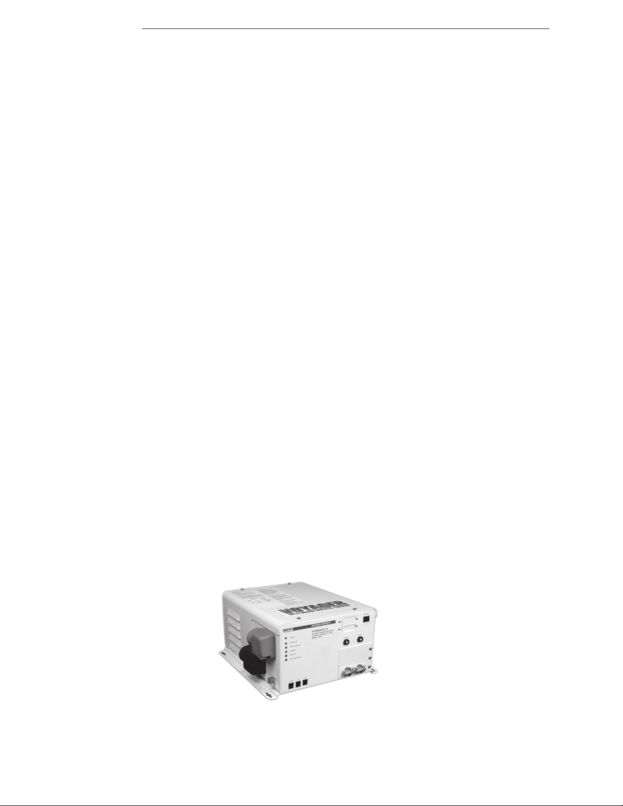
Figure 1
The Voyager Inverter/Charger
(Series II shown)
2000 Trace Engineering
Page 7

Voyager Series
1.0 INTRODUCTION
1.1 Features and Benefits
Congratulations on purchasing one of the most flexible, reliable, easy-to-install inverters ever produced
for the marine industry: the Voyager Series from Trace Engineering.
Built and tested to withstand even the toughest marine environment, Voyager’s rugged aluminum
construction and corrosion resistant design make it the inverter of choice for boaters, professional marine
installers and original equipment manufacturers throughout the world.
Voyager is flexible enough to meet even the most demanding powering needs, yet simple to operate.
With the optional menu-driven remote control, configuration and setup is as simple as pressing a button no more jumpers or DIP switches to worry about.
Installation is easy: connect the inverter’s output to the distribution panel’s input; connect the AC (shore
power) cable to the inverter’s front panel terminal block; connect the batteries, and then switch on the power.
To ensure the highest level of electrical safety, Voyager is UL Listed and meets the stringent requirements of UL458. Add to that a 3-year warranty and the backing of the world’s largest and most successful
inverter manufacturer and what you have is one powerful marine inverter.
1.2 Standard Features
Continuous inverter power
Voyager Series I –
V1012 – 1,000 watts
V1512 – 1,500 watts
Voyager Series II -
V2012 – 2,000 watts
V2512 – 2,500 watts
V3012 – 3,000 watts
3-stage battery charging with temperature compensation
Battery temperature sensor
Selectable charging profiles for Liquid Lead Acid, GEL or AGM battery types
High / low battery protection circuitry
Over-temperature / over-current protection
Automatic neutral / ground bond switching (per UL and NEC)
Dual AC outputs with built-in circuit breakers (except 2.5 and 3.0 KW models)
30 amp transfer relay
36 month warranty
1.3 Optional Features
RC8 - remote ON/OFF switch and status indicator
RC5 - full function, programmable remote control
URC - full function, digital remote control
TFB - high current, class T fuse in fuse block
BCx - UL listed battery cable kits
2000 Trace Engineering
1
Page 8
Voyager Series
1.0 INTRODUCTION
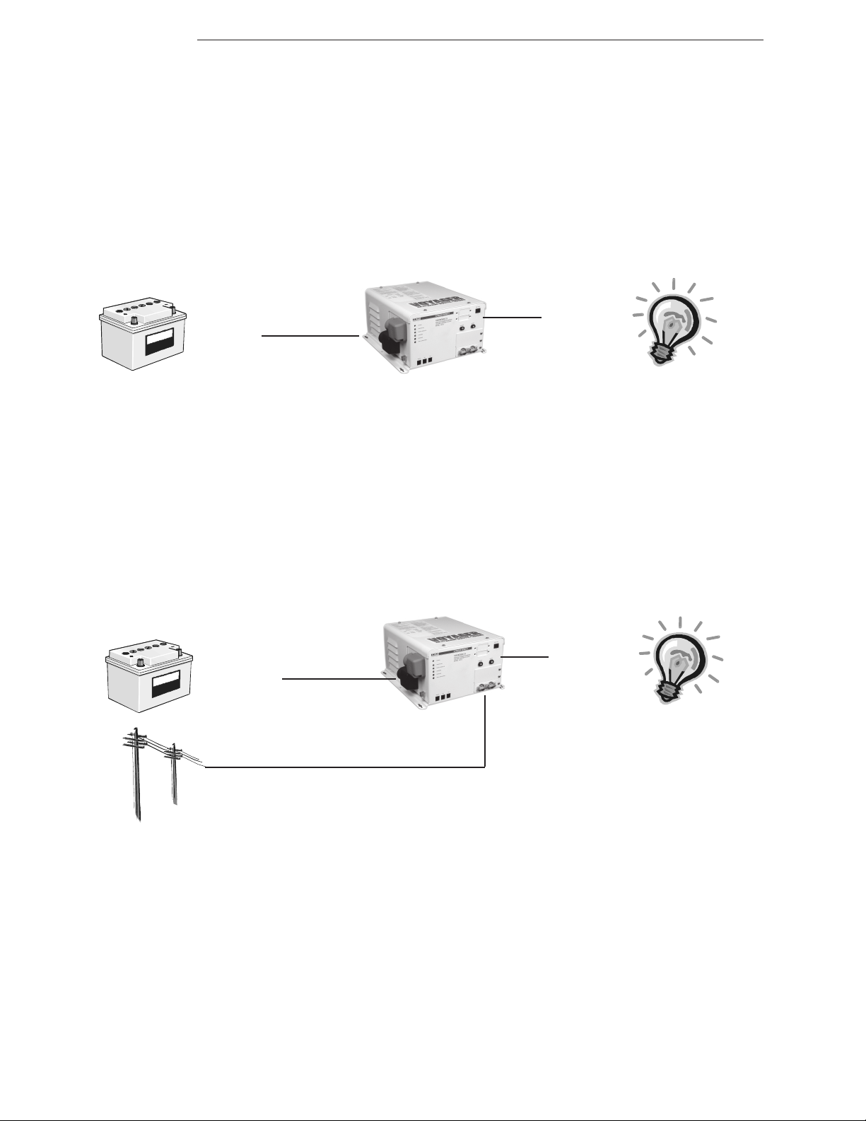
DC INPUT
(from Batteries)
Figure 2
Inverter Mode
AC OUTPUT
(to Load)
AC OUTPUT
DC OUTPUT
(to Batteries)
AC INPUT
(from Utility or Generator)
(to Load)
Figure 3
Charge Mode
2
2000 Trace Engineering
Page 9

Voyager Series
1.0 INTRODUCTION
1.4 How an Inverter/Charger Works
An inverter essentially transforms direct current (DC) into alternating current (AC). It also takes
alternating current and transforms it back into direct current.
Inverter Mode:
Direct current (DC) is taken from the batteries and transformed to alternating current (AC) for use with
household appliances (figure 2).
Charge Mode:
Alternating current (AC) is taken from the utility (shore power) and passed directly to the connected load
(household appliances). A portion of the AC is transformed back to DC and used to recharge the
batteries (figure 3).
1.5 What an Inverter Can Power
The Voyager Series inverter/charger can power a wide range of loads such as household appliances,
small motors and other electrical devices. Actual run time depends on several variables including the size
and the type of load. Battery type, capacity, and age; the battery’s state of charge; and temperature also
affect run times.
Size of the Load (Watts or Volt Amps)
Electrical appliances are rated by the amount of power they consume (table 1). The rating is
printed on the product’s nameplate label, usually located on its chassis near the AC power cord.
Type of Load (Resistive or Inductive)
Toasters, coffee pots and incandescent lights are typical resistive loads. They are the simplest and
most efficient for an inverter to power. Large resistive loads, such as electric stoves and water heaters,
are impractical to use with an inverter since the high current demands would quickly drain the batteries.
TVs, VCRs, stereos, computers, etc., contain transformers and are considered inductive. These loads
require more current than a resistive load of the same wattage rating because of the transformer’s start-
up characteristics. Electric motors are also inductive; however, depending upon the size of the motor, it can
require 2 to 6 times its running current to start, momentarily exceeding the inverter’s maximum output
rating. Only testing a specific load will determine if it can be started and how long it will run.
RUN TIME IN MINUTES 5 15 30 60 120 240
Appliance Watts
Fluorescent Lamp 10 0.1 0.3 0.7 1.3 2.7 5.3
B&W TV 50 0.4 124817
Computer 100 12481734
Color TV 200 248173467
Blender 400 3 8 17 34 67 133
Circular Saw 800 6 17 34 67 133 266
Toaster 1000 8 23 46 93 185 370
Microwave 1200 10 28 57 114 227 455
Hot Plate 1800 15 44 88 176 353 706
BATTERY AMP-HOURS REQUIRED (12 Volt System)
2000 Trace Engineering
Table 1
Typical Power Consumption of Common Appliances
3
Page 10
Voyager Series
1.0 INTRODUCTION
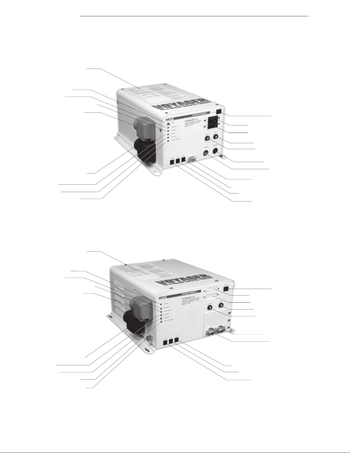
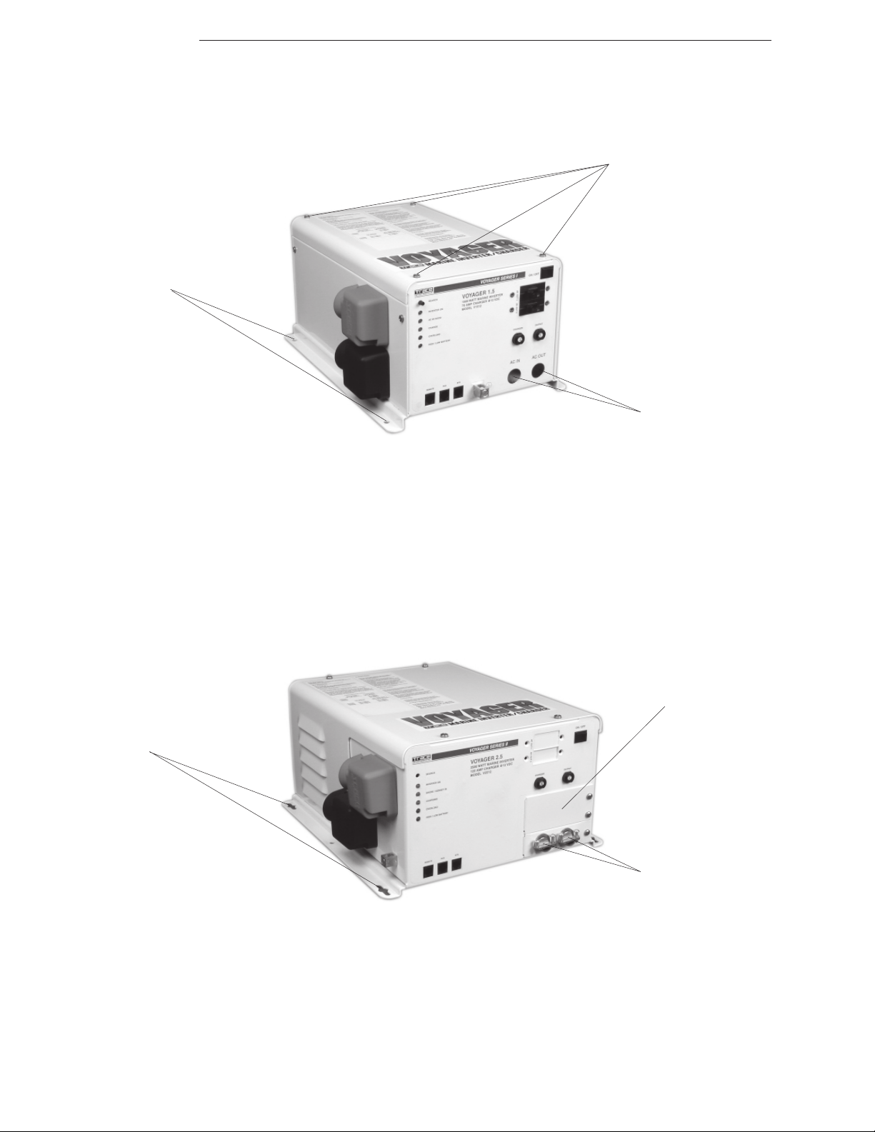
Voyager Nameplate Label
Search Adjustment
Inverter ON LED
AC IN (Shore Power) Good LED
Positive Battery Terminal
Negative Battery Terminal
Charge LED
Overload LED
High / Low Battery LED
ON / OFF Switch
AC Output 1 Circuit Breaker
AC Output 2 Circuit Breaker
AC Input Circuit Breaker
Charger Circuit Breaker
AC Output Knockout
AC Input Knockout
Chassis Ground Connector
BTS(Battery Temp Sensor) Connector
RC8 (Remote ON/OFF) Connector
Remote Control Connector
Voyager Nameplate Label
Search Adjustment
Inverter ON LED
AC IN (Shore Power) Good LED
Positive Battery Terminal
Negative Battery Terminal
Charge LED
Overload LED
High / Low Battery LED
Chassis Ground Connector
Figure 4
The Voyager Series I Inverter/Charger
ON / OFF Switch
AC Output 1 Circuit Breaker
AC Output 2 Circuit Breaker
AC Input Circuit Breaker
Charger Circuit Breaker
AC Output Knockout
AC Input Knockout
BTS(Battery Temp Sensor) Connector
RC8 (Remote ON/OFF) Connector
Remote Control Connector
Figure 5
The Voyager Series II Inverter/Charger
4
2000 Trace Engineering
Page 11

Voyager Series
1.0 INTRODUCTION
1.6 A Quick Tour
Voyager Series I and Voyager Series II inverter/chargers differ slightly in size of the units and in the layout
of control features. Each unit is designed to allow easy access to wiring, circuit breakers, controls and status
indicators.
ON / OFF Switch - manually switches the inverter ON and OFF.
Search Adjustment Potentiometer - sets the minimum load required to automatically switch the inverter’s
output ON.
LED Indicators - displays the operational status of the inverter:
Inverter ON - connected loads are being powered from the batteries.
AC IN (Shore Power) Good - connected loads are being powered by utility AC (shore power).
Charge - batteries are being charged.
Overload - inverter is output is overloaded or the inverter is overheated.
High / Low Battery - inverter has shutdown due to a high or low battery condition.
Remote Control Connector - accepts the RC5 or URC remote control cable.
RC8 Connector - accepts the RC8 remote ON / OFF switch cable.
BTS Connector - accepts the remote battery temperature sensor cable.
Positive Battery Terminal - accepts the positive (+) cable from the house batteries.
Negative Battery Terminal - accepts the negative (-) cable from the house batteries.
Chassis Ground Connector - accepts chassis ground cable.
AC Input Knockout - routes AC input (shore power) conduit (hot, neutral and ground wiring) to the internal
terminal block.
AC Output Knockout - routes AC output conduit (with hot, neutral and ground wiring) from the internal
terminal block.
AC Input Circuit Breaker - protects main AC (shore power) input circuit.
AC Output 1 Circuit Breaker - protects the primary AC output circuit.
AC Output 2 Circuit Breaker - protects secondary AC output circuit.
Charger Circuit Breaker - protects DC charging circuit.
Voyager Nameplate Label - contains useful product and safety information.
2000 Trace Engineering
5
Page 12

Voyager Series
2.0 INSTALLATION
2.1 Unpacking and Inspection
Carefully remove the inverter from its shipping container and inspect all contents listed on the packaging
checklist. If items appear to be damaged or missing, contact Trace Engineering’s Customer Service department
at (360) 435-8826. It is recommended that you retain the shipping container in the event the unit ever needs to
be returned for factory service.
2.2 Pre-Installation
Before installing the inverter, read all instructions and cautionary markings located in this manual. On
U.S vessels, installations must conform to the requirements of 33 CFR 183.410.
NOTE: The inverter is quite heavy. Always use proper lifting techniques during installation to prevent
personal injury.
2.2.1 Locating the Inverter
The inverter must be mounted in a clean, dry, ventilated environment where the ambient temperature will
not exceed 122 ºF (50 ºC). The location must be fully accessible and protected from exposure to dry engine
exhaust and other heat producing devices. The inverter can be mounted either horizontally or vertically and
must be securely fastened to bulkheads or other vessel structural parts.
The base of the inverter must be at least two feet above normal bilge water or protected so that it is not
subject to bilge splash. Additional protection, such as a drip shield, must be installed to protect the inverter
from falling objects or drippage.
Allow adequate clearance to remove the inverter’s cover (Series I) and to access the front panel and
controls (Series I and II).
The inverter should be located as close as possible to the batteries in order to keep the battery cables
short; however, it should not be mounted directly above them. Due to the corrosive nature of batteries,
especially with electronics, make sure the area is adequately ventilated to the outside.
CAUTION: Do not mount the inverter in the engine room or near the fuel tanks of gasoline-fueled vessels.
2.2.2 Locating the Batteries
Like the inverter, the batteries must be mounted in a clean, dry, ventilated environment where they are
protected from high and low ambient temperatures. The location must be fully accessible and protected
from exposure to dry engine exhaust and other heat producing devices. The batteries must be mounted
upright (liquid batteries only) and securely fastened to the mounting surface.
The base of the batteries must be at least two feet above normal bilge water and protected so that they
will not subject to bilge splash. For optimum performance, a ventilated battery enclosure is recommended.
The batteries should be located as close as possible to the inverter in order to keep the battery cables
short; however, they should not be mounted directly under the inverter. Due to the corrosive nature of
batteries, especially with electronics, make sure the area is adequately ventilated to the outside.
CAUTION: Do not mount the batteries in the engine room or near the fuel tanks of gasoline-fueled vessels.
6
2000 Trace Engineering
Page 13

Voyager Series
2.0 INSTALLATION
2.2.3 Battery Selection
Proper battery selection is critical to the optimum performance of an inverter system. Batteries come in
variety of sizes, types (starting, deep cycle), capacities (amp-hours), voltages (6 VDC, 12 VDC), chemistries
(NiFe, NiCAD, Lead Acid), and construction (sealed or vented), each designed for a specific application.
The 3 types of batteries recommended for use with Voyager Series inverters are: Liquid Lead Acid (LEAD),
Sealed Gell Cells (GEL) and Sealed Absorbed Glass Mat (AGM).
NOTE: DO NOT use automotive (starting) batteries - they are designed to provide high starting current for
short periods of time; whereas, batteries used in inverter applications must provide low, constant current for
long periods of time (deep cycled).
2.2.3.1 Liquid Lead Acid Batteries (LEAD)
Liquid Lead Acid batteries are designed to be deep cycled before being recharged, making them suitable for
inverter applications. These batteries require periodic maintenance consisting mainly of adding distilled water to
the cells, checking battery cable connectors for tightness and keeping the terminals clean.
RV and Marine (“Group 24” or “Group 27”)
“OK” for small systems
Designed for limited cycling
Do not last as long as the other “true” deep cycle batteries
Typically rated at 12 volts DC (80 to 100 amp-hours)
Golf Cart (“T-105,” “CG220,” or “L16”)
“Better” for small systems
Designed for repeated discharge (up to 80%) without damage
Rugged, long lasting
Typically rated at 6 volts DC (220 to 350 amp-hours)
2.2.3.2 Sealed Batteries (GEL and AGM)
Both GEL and AGM batteries are virtually maintenance free, making them ideal for inverter applications.
Since the batteries are completely sealed, they can be mounted in almost any position. The only disadvantages, compared to flooded batteries, are a higher initial cost and greater susceptibility to overcharging.
Gel Cell
Gelled electrolyte instead of liquid
Long life (up to 1500 cycles, typical)
Low self-discharge
Virtually maintenance-free
Absorbed Glass Mat
“Best” for inverter-type applications
Electrolyte is contained in glass-fiber mats between battery plates
Good low temperature performance
Virtually maintenance-free
2000 Trace Engineering
7
Page 14

Voyager Series
2.0 INSTALLATION
2.2.4 Tools Required
Drill Level Wire strippers
1/4" (6mm) slotted screw driver Pliers Electrical tape
1/2" (13mm) open-end wrench Pencil Multimeter
Socket wrench and fittings Utility knife Torque wrench
2.2.5 Hardware / Materials Required
1/4" mounting bolts and lock washers
3/16” screws (with washers, lock washers, nuts)
Flexible (vibration absorbent) washers
Conduit, strain-reliefs and appropriate fittings
Wire ties
2.2.6 Wiring
All wiring and installation methods must conform to applicable electrical and marine codes. AC wiring
must be no less than #10 AWG copper wire and rated for 75 °C or higher. Battery cables must be rated for 75
°C or higher and should be no less than the minimum size wire recommended by this manual. Wiring must be
installed in a manner that will avoid magnetic loops in the area of the compass and magnetically sensitive
devices.
Pre-plan the wire and conduit runs. For maximum safety, run both AC and DC wires/cables in (separate)
conduit. Direct current wiring, due to its potential to generate RFI, must be tied together with electrical tape.
NOTE: Run DC cabling in twisted pairs, keeping the runs as short as practical.
2.2.6.1 AC Connections
External connections to this unit must comply with United States Coast Guard electrical regulations
(33 CFR 183, Sub part I). Use #10 AWG (or larger) THHN wire for all AC wiring. The inverter’s AC terminal
blocks accept up to #6 AWG wire.
2.2.6.2 DC Connections
Battery to inverter cabling should be only as long as required. If #2/0 AWG cables are used for example, do
not exceed 5 feet (one way) in 12 VDC systems. For optimum performance, use pre-assembled battery cables
from Trace Engineering, designed specifically for this application.
Crimped and sealed copper ring terminal lugs with a 5/16” hole should be used to connect the battery
cables to the inverter’s DC terminals.
2.2.6.3 AC Grounding
The inverter/charger includes neutral-to-ground switching for the AC electrical system.
WARNING: The shore power neutral must only be grounded through the shore power cable. Do not permanently
ground it on board the vessel.
8
2000 Trace Engineering
Page 15

Voyager Series
2.0 INSTALLATION
2.2.6.4 DC Grounding
The inverter/charger should be connected to a grounded, permanent wiring system. For most
installations, the negative battery conductor should be bonded to the vessel safety-grounding conductor
(green wire) at only one point in the system as per ABYC standard E-8.5 and E-9.20. The size for the
conductor is usually based on the size of the largest conductor in the DC system. DO NOT connect the battery
negative (-) cable to the vessel safety ground; connect it to the battery negative terminal of the inverter. NO NOT
connect equipment DC negatives to the safety ground, connect only to the negative bus of the DC load center.
2.2.7 Torque Requirements
Torque all AC wiring connections to 16 inch pounds. Torque DC cable connections to 10-12 foot pounds.
2.2.8 Main Service Panel
The input to the inverter requires a minimum 60 amp circuit breaker at the main service panel.
2.2.9 Sub Panel
Loads powered by the inverter need to be rerouted from the main service panel to a sub panel. This can be
done several different ways, depending upon the installation. Always refer to electrical codes for safe wiring
practices.
2.2.10 Circuit Protection
Use only input circuits provided with the correct ampere branch circuit protection in accordance with the
National Electric Code, ANSI/ NFPA70. Always use a properly rated circuit breaker. Depending upon the
application, circuit breakers used to protect the load can be removed from the main service panel and put
into the sub-panel ONLY if the two panels are from the same manufacturer and are the same type of
service panel.
NOTE: Both AC and DC disconnects / overcurrent protection must be provided as part of the installation.
2.2.11 Wire Routing
Determine all wire routes both to and from the inverter. Current carrying conductors must be routed as
high as practical above the bilge water level and other area where water can accumulate. If conductors must
be routed in the bilge or other areas where water can accumulate, the connections must be watertight.
Conductors that may be exposed to physical damage must be protected by conduit, tape, raceways, or
other equivalent protection. Conductors passing through bulkheads or structural members must be protected to
minimize insulation damage such as chafing. Conductors must also be routed clear of sources of chafing such
as steering cable and linkages, engine shafts, and control surfaces.
Possible routing scenarios include:
AC Input wiring from the main service panel (or shore power source) to the inverter
AC Input wiring from the generator to the inverter
DC Input wiring from the batteries to the inverter
AC Output wiring from the inverter to the sub-panel
Battery Temperature Sensor cable from the inverter to the batteries
Remote Control cable to the inverter
Ground wiring from the inverter to an external ground
Check for existing electrical, plumbing or other potential areas of accidental damage prior to making cuts in
structural surfaces, bulkheads or decks.
2000 Trace Engineering
9
Page 16
Voyager Series
2.0 INSTALLATION
Chassis Mounting Holes
(both sides)
Series I Cover Screws
(remove to access AC Terminal Block)
AC Input and Output
Conduit Clamps
Chassis Mounting Holes
(both sides)
Figure 6
Series I Mounting
Series II Cover Plate
(remove to access AC Terminal Block)
AC Input and Output
Conduit Clamps
10
Figure 7
Series II Mounting
2000 Trace Engineering
Page 17

Voyager Series
2.0 INSTALLATION
2.3 Installation
Before installing the inverter and batteries, read all instructions and cautionary markings located at the
beginning of this manual and in the pre-installation section. On U.S vessels, installations must conform to the
requirements of 33 CFR 183.410.
2.3.1 Inverter Mounting
Place the inverter in the designated mounting location either horizontally or vertically. Allow adequate
clearance to remove the inverter’s cover (Series I) and to access the front panel (Series I and II).
Also allow for air flow in to and around the inverter, especially near the cooling fan (approximately 3”).
Mark the mounting holes in the base of the inverter’s chassis. Drill out pilot holes in the mounting surface.
If the inverter is mounted in an area or potential exposure to spray or splashing, install the drip shield
above the inverter. The drip shield does not mount to the inverter’s chassis. This is required per UL for
bulkhead mounting.
CAUTION: DO NOT mount the inverter in the engine room or near the fuel tanks of gasoline-fueled vessels.
Remove the four cover screws (Voyager Series I only) and remove the cover. Loosen the front panel
conduit clamps to accept the AC Input and Output wiring and conduit.
Remove the two coverplate screws (Voyager Series II only) and remove the coverplate. Loosen the front
panel conduit clamps to accept the AC Input and Output wiring and conduit.
2000 Trace Engineering
11
Page 18
Voyager Series
2.0 INSTALLATION
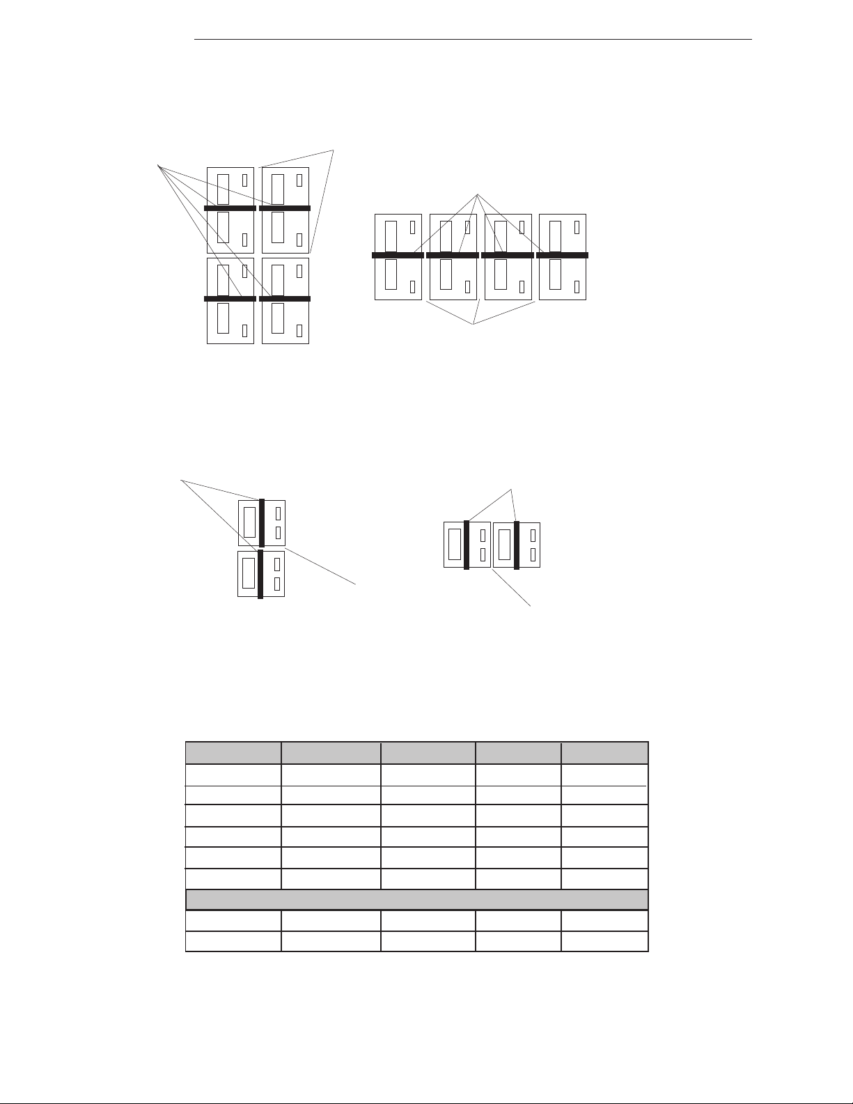
Battery Hold-down Clamps
Battery Hold-down Clamps
1” Spacing
-
+
-
+
-
Battery Hold-down Clamps
-
-
+
+
+
Figure 8
Battery Position and Mounting
(four 12 VDC Batteries)
+
1” Spacing
-
+
Battery Hold-down Clamps
-
+
+
-
+
1” Spacing
+
+
1” Spacing
12
Figure 9
Battery Position and Mounting
(two 6 VDC Batteries)
Inverter DC Rating 1 to 3 feet 3 to 5 ft 5 to 10 ft
Model # (typical) (one way) (one way) (one way)
V1012 100 Amps 2/0 AWG 4/0 AWG 4/0 AWG
V1512 150 Amps 2/0 AWG 4/0 AWG 4/0 AWG
V2012 200 Amps 2/0 AWG 4/0 AWG 4/0 AWG
V2512 250 Amps 4/0 AWG 4/0 AWG 4/0 AWG
V3012 300 Amps 4/0 AWG 4/0 AWG 2x2/0 AWG
Trace Engineering Battery Cables
Trace P/N 2/0 Cables BC3-2/0 use BC5-4/0 use BC10-4/0
Trace P/N 4/0 Cables BC3-4/0 BC5-4/0 BC10-4/0
Table 2
Recommended Battery Cable Sizes (Free Air Rating)
2000 Trace Engineering
Page 19

Voyager Series
2.0 INSTALLATION
2.3.2 Battery Installation
Refer to the battery safety information at the beginning of the manual and in the pre-installation section
before proceeding. To ensure optimum performance from your inverter system, never use old or untested
batteries. All batteries must be of the same size, type, rating and age.
To ensure maximum performance from the batteries, as well as provide protection from high and low
temperatures, mount the batteries in an insulated enclosure, ventilated to the outside from the top of the
enclosure (1” diameter opening).
CAUTION: DO NOT mount the batteries in the engine room or near the fuel tanks of gasoline-fueled vessels.
NOTE: Flooded Lead Acid batteries must be mounted upright.
NOTE: Align the batteries so that all positive terminals are located on the same side (figures 8 and 9). This will
help ensure proper wiring and polarity identification.
Place the batteries as close as practical to the inverter, preferably in an insulated and ventilated
enclosure. Allow adequate space above the batteries (+/- 6” above the batteries) to access the
terminals and vent caps (if applicable). Also allow at least 1” of space between the batteries to provide
good air flow. DO NOT mount the batteries directly under the inverter.
Secure the batteries to the mounting surface with battery hold down clamps.
2.3.3 Battery Cables and Sizing
Using the proper size (gauge) and length of battery cable is critical to the safe and efficient operation of the
inverter. Undersized cables result in lower efficiency, reduced surge power and lower peak output voltage. They
can also pose a potential fire hazard. Long cable runs also reduce efficiency due to resistance in the cable.
Always keep cable runs a short as practical.
Battery cables must be color coded with colored tape or heat shrink tubing: RED for positive (+); BLACK for
negative (-); and GREEN for DC ground.
All battery cables must have soldered and crimped lugs, crimped copper compression lugs, or aluminum
mechanical lugs. Soldered connections alone are not acceptable for marine applications.
UL Listed, Trace Engineering battery cables with lug connectors, designed specifically for inverter applications, are available from your Trace dealer (table 2). Cables come color-coded with pressure crimped, sealed
ring terminals and are available in both 2/0 or 4/0 AWG sizes, ranging in lengths from 1 to 10 feet.
2000 Trace Engineering
Figure 10
Trace Battery Cable with Color-coded Lug Connector
13
Page 20

Voyager Series
2.0 INSTALLATION
DC Load Center
Grounding / Bonding
DC Negative Bus
DC Positive Bus
DC Fuse
or Disconnect
House Batteries
Cranking Motor
Starting Batteries
Vessel Grounding Conductor
Figure 11
Typical DC Wiring
(Voyager Series I)
Engine
Engine
Negative Terminal
Engine
14
DC Load Center
Grounding / Bonding
DC Negative Bus
DC Positive Bus
DC Fuse
or Disconnect
House Batteries
Cranking Motor
Starting Batteries
Vessel Grounding Conductor
Figure 12
Typical DC Wiring
(Voyager Series II)
Engine
Engine
Negative Terminal
Engine
2000 Trace Engineering
Page 21

Voyager Series
2.0 INSTALLATION
2.3.4 DC Wiring (Refer to figures 11 (Series I) and 12 (Series II) wiring diagrams).
Refer to the safety information at the beginning of the manual and in the pre-installation section before
proceeding. DC wires and cables must be tied together with electrical tape every 6 inches. Avoid magnetic
loops in the area of the compass and magnetically sensitive devices.
Conductors passing through bulkheads or structural members must be routed clear of steering cable,
linkages, engine shafts, and control surfaces to protect against insulation damage such as chafing.
WARNING: De-energize all on-board sources of power including batteries (DC), shore power (AC), and
AC generator (if applicable).
NOTE: DO NOT connect the battery cables to the inverter until all wiring is complete and the correct DC voltage
and polarity is confirmed.
NOTE: All cables must have a smooth bend radius. Place the long cable runs in dedicated flex conduit
(plastic) and follow existing wire runs where possible. Dress the runs neatly with wire ties.
DC Grounding
Verify the ground connection between the DC negative bus and ground bus in DC load center.
Verify the ground connection between the engine negative terminal and the ground bus in DC load
center.
Route the vessel grounding cable between the negative engine terminal and the inverter’s ground lug.
Connect the grounds.
Negative Cables
Route a negative cable from the DC negative bus in the DC load center to the house battery bank.
Route a negative cable from the house battery bank to the inverter’s negative terminal connector.
Co-connect both cables (inverter negative and DC negative bus) on the negative battery terminal
(refer to figure 13 for battery wiring).
Connect the negative inverter cable to the inverter’s black negative terminal connector.
Positive Cables
Route a positive cable from the DC positive bus in the DC load center to the house battery bank.
Route a positive cable from the house battery bank to the Fuse Block assembly (DC Disconnect).
Route a positive cable from the Fuse Block assembly (DC Disconnect) to the inverter’s positive
terminal connector.
DO NOT connect the positive cables to the batteries or inverter at this time.
2000 Trace Engineering
15
Page 22

Voyager Series
2.0 INSTALLATION
Ring washer
Lock washer
Nut
Terminal
Battery Cable Lug
Ring washer
Bolt
+
Positive Battery
Cable and Lug
NOTE: Terminal and cable photos are for illustrative purposes only
12 VDC
100 AHr
12 VDC
100 AHr
Negative Battery
Cable and Lug
(to DC negative bus)
Figure 13
Negative and Positive Terminal Wiring (all batteries)
-
6 VDC
100 AHr
-
Negative Battery
Cable and Lug
(to inverter)
-
12 VDC
100 AHr
12 VDC
100 AHr
Figure 14
12 VDC Parallel Configuration
(using four 12 Volt, 100 AHr batteries)
16
+
Total
Output
12 VDC
400 AHr
6 VDC
100 AHr
+
Figure 15
12 VDC Series Configuration
(using two 6 Volt, 100 AHr batteries)
2000 Trace Engineering
Total
Output
12 VDC
100 AHr
Page 23

Voyager Series
2.0 INSTALLATION
2.3.5 Battery Wiring
Depending upon the type of battery used in the installation (6 or 12 VDC), the batteries must be wired in
series, parallel or series/parallel to provide 12 VDC. The interconnecting battery cables must be sized and rated
the same as those that used to connect to the inverter.
Follow the battery terminal wiring example (figure 13) to ensure the cables are properly connected to the
batteries. As a general guideline hardware should be installed in the following order: bolt, ring washer, cable lug,
(battery terminal), ring washer, lock washer, nut. Tighten terminal connections to at least 10 to 12 foot pounds.
When two cable lugs are connected to a single terminal (such as with the negative terminal), the hardware
should be installed in the following order: bolt, ring washer, DC negative cable lug, inverter negative cable lug,
(battery terminal), ring washer, lock washer, nut.
Once the batteries are completely wired and tested, coat the terminals with an approved anti-oxidizing
spray.
WARNING: Cover exposed cable ends with electrical tape to prevent shorting the cables.
NOTE: DO NOT connect the positive cable to the inverter at this time.
2.3.5.1 Parallel Connection (multiple 12 VDC batteries to create a 12 VDC string)
A parallel connection combines the overall capacity by the number of batteries in the string while the
voltage remains the same. In the example (figure 14), four, 12 VDC, 100 AHr batteries are combined into a
single string resulting in a 12 VDC, 400 AHr bank.
Connect the negative battery terminals together using short cables (figure 14).
Connect the positive battery terminals together using short cables.
Connect the long battery cable (from the inverter) to the negative terminal of the end battery. At the
same time, connect a DC ground cable between the negative terminal and the vessel’s DC grounding
bus.
Connect the other long battery cable (from the inverter) to the positive terminal of the opposite end
battery. This is essential to ensure even charging and discharging across the entire battery string.
NOTE: A fuse must be placed between the positive terminal and the long battery cable to the inverter.
2.3.5.2 Series Connection (two 6 VDC batteries to create a 12 VDC string)
A series connection combines the overall voltage by the number of batteries in the string while the
capacity remains the same. In the example (figure 15), two, 6 VDC, 100 AHr batteries are combined into a
single string resulting in a 12 VDC, 100 AHr bank.
Connect the negative battery terminal of one battery to the positive of the other using a short cable
(figure 13).
Connect the long battery cable (from the inverter) to the open negative terminal of one battery. At the
same time, connect a DC ground cable between the negative terminal and the vessel’s DC grounding
bus.
Connect the other long battery cable (from the inverter) to the open positive terminal of the other
battery.
NOTE: A fuse must be placed between the positive terminal and the long battery cable to the inverter.
2000 Trace Engineering
17
Page 24

Voyager Series
2.0 INSTALLATION
-
6 VDC
100 AHr
6 VDC
100 AHr
6 VDC
100 AHr
6 VDC
100 AHr
+
Figure 16
12 VDC Series/Parallel Configuration
(using four 6 volt batteries)
Figure 17
Fuse Block Assembly
Total
Output
12 VDC
200 AHr
18
Cable Size Rating (in Free Air) Fuse Size (Max) Trace P/N
2/0 AWG 265 amps (max) 300 amps TFB300
4/0 AWG 360 amps (max) 400 amps TFB400
Table 3
Recommended DC Protection
2000 Trace Engineering
Page 25

Voyager Series
2.0 INSTALLATION
2.3.5.3 Series/Parallel Connection (multiple 6 VDC batteries to create a 12 VDC string)
A series/parallel connection increases both voltage and capacity using smaller, lower-voltage batteries.
In the example (figure 16) four, 6 VDC, 100 AHr batteries are combined into two pairs resulting in a 12 VDC,
200 AHr bank.
Connect the negative battery terminal of one 6 VDC battery to the positive of the next (creating a pair)
using a short battery cable.
Connect the negative battery terminal of another 6 VDC battery to the positive of its next (creating a
second pair) using a short battery cable.
Connect the remaining negative battery terminal of the first pair to that of the second pair using a short
battery cable.
Connect the remaining positive battery terminal of the first pair to that of the second pair using a short
battery cable.
Connect the long negative battery cable (from the inverter) to the end battery’s negative terminal. At
the same time, connect a DC ground cable between the negative terminal and the vessel’s DC
grounding bus.
Connect the long positive battery cable (from the inverter) to the opposite end battery’s positive
terminal.
NOTE: A fuse must be placed between the positive terminal and the long battery cable to the inverter.
2.3.6 DC Fuse Block (or Circuit Breaker Assembly) Installation and Wiring
The ABYC and Federal Regulations require a fuse or circuit breaker to be located within 72 inches of the
battery to protect the DC wiring system. The device must be rated to match the size of the cable, but can be
rounded up to the next size (i.e., a cable rated at 150 amps can accept a 175 amp fuse) as necessary.
DC-rated class T fuses and safety-covered fuse blocks, recommended for use with the Voyager Series
inverter, are available in 110, 200, 300, and 400 amp sizes from your Trace dealer.
Mount the fuse block (or circuit breaker assembly) as near as practical to the batteries using (4)
3/16” screws (with washers, lock washers, nuts).
Remove the fuse (or open the circuit breaker) and connect a short cable (same rating as the battery
cables) to one end of the fuse block.
Connect the short cable to the positive battery terminal (figure 13).
Connect the long positive cable (from the inverter) to the assembly. DO NOT connect the positive
cable to the inverter at this time.
Securely tighten the fuse block’s lugs and put the plastic cover on the fuse block.
After the entire installation is complete, reinsert the fuse into the fuse block prior to connecting the
positive cable to the inverter (section 2.6).
2000 Trace Engineering
19
Page 26

Voyager Series
2.0 INSTALLATION
AC (Shore Power) IN Generator IN
Switch
Non-Inverter Loads
Range
Water Heater
Air Conditioner
AC IN / AC OUT
Main Panel
Sub Panel
Typical AC Wiring
(Voyager Series I)
AC (Shore Power) IN Generator IN
Switch
Non-Inverter Loads
Range
Water Heater
Air Conditioner
Inverter Loads
Lights
TV/VCR
Microwave
Refrigerator
Outlets
Figure 18
20
Main Panel
Inverter Loads
TV/VCR
Microwave
Refrigerator
Sub Panel
Figure 19
Typical AC Wiring
(Voyager Series II)
AC IN / AC OUT
Lights
Outlets
2000 Trace Engineering
Page 27

Voyager Series
2.0 INSTALLATION
2.3.7 AC Wiring (refer to figures 18 (Series I) and 19 (Series II) wiring diagrams).
Refer to the safety information at the beginning of the manual and in the pre-installation section before
proceeding. ABYC standards require a disconnect switch or main service panel within 10 feet of the shore
power input receptacle.
WARNING: AC wiring must be performed by a qualified person or licensed electrician.
WARNING: De-energize all on-board sources of power including batteries (DC), shore power (AC), and
AC generator (if applicable). Verify circuits are de-energized using a multimeter.
WARNING: The inverter/charger includes neutral-to-ground switching for the AC electrical system. In marine
installations, loads powered by the inverter must have the AC neutral physically isolated from the ground.
Isolate the sub panel’s neutral bus from its frame using an appropriate insulator.
CAUTION: DO NOT connect the inverter’s output to an AC power source.
CAUTION: DO NOT connect the battery cables to the inverter until all AC wiring is complete.
NOTE: All cables must have a smooth bend radius. Place cables in conduit and follow existing wire runs
where possible. DO NOT place AC cabling in the same conduit with DC cabling. Conductors passing through
bulkheads or structural members must be routed clear of steering cable, linkages, engine shafts, and control
surfaces to protect against insulation damage such as chafing.
NOTE: Heavy loads such as the water heater, air conditioner, electric range and conventional oven should not be
run from the inverter. Those circuits should remain connected to the main electrical panel. Other circuits, for
loads such as lights, standard electrical outlets, etc., should be rerouted from the main panel to the sub panel.
AC Input (Shore Power) Routing
Route the 30 amp service (shore power) to the main panel. If the installation includes a generator,
route the 30 amp service (shore power) to an approved selector switch and then to the main panel.
AC Input (Generator) Routing
Route the 30 amp service (generator) to an approved selector switch and then to the main panel.
Main Panel Routing
Route the AC output from the main panel’s 30 amp breaker to the inverter’s internal terminal block.
Sub Panel Routing
Route the AC output from the inverter’s internal terminal block to the sub panel’s main breaker.
Inverter Power AC Input AC Input AC Output
Model # Rating Breaker (120 VAC) (120 VAC)
V1012 1000 VA 30 Amp 10 AWG 10 AWG
V1512 1500 VA 30 Amp 10 AWG 10 AWG
V2012 2000 VA 30 Amp 10 AWG 10 AWG
V2512 2500 VA 30 Amp 10 AWG 10 AWG
V3012 3000 VA 30 Amp 10 AWG 10 AWG
2000 Trace Engineering
Table 4
Recommended AC Wire Sizes
21
Page 28

Voyager Series
2.0 INSTALLATION
Series I Cover Screws
(remove to access AC Terminal Block)
Figure 20
AC Terminal Block Access
Ground
AC IN (Neu)
(remove to access AC Terminal Block)
Series II Cover Plate
AC OUT (Neu)
AC OUT 1 (Hot)
AC IN (Hot)
Main Panel (circuit breaker)
Main Panel (neutral bus)
Main Panel (ground)
AC OUT 2 (Hot)
Convenience Outlet
Sub Panel (main circuit breaker)
Sub Panel (neutral bus)
Sub Panel (ground)
Figure 21
Internal AC Terminal Block
22
2000 Trace Engineering
Page 29

Voyager Series
2.0 INSTALLATION
2.3.7.1 Inverter AC Input
Route the cable and conduit from the main panel to the inverter’s AC INPUT conduit clamp. Tighten
the clamp securely on the conduit. Always leave a little extra slack in the wiring.
Remove the chassis cover (Series I) or the front panel (Series II) to access the internal terminal block.
Connect the black wire (HOT) from the main panel’s dedicated 30 amp breaker to the left hand “AC
INPUT (HOT)” terminal. Tighten the terminal to 16 inch-pounds.
Connect the white wire (NEU) from the main panel’s neutral bus bar to the “AC INPUT (NEU)” terminal.
Tighten the terminal to 16 inch-pounds.
Connect the green wire (GROUND) from the main panel’s neutral bus bar to the “GROUND” terminal.
Tighten the terminal to 16 inch-pounds.
2.3.7.2 Inverter AC Output
Route the cable and conduit from the sub panel to the inverter’s AC OUTPUT conduit clamp. Tighten
the clamp securely on the conduit. Always leave a little extra slack in the wiring.
Remove the chassis cover (Series I) or the front panel (Series II) to access the internal terminal block.
Connect the black wire (HOT) to the “AC OUTPUT 1 (HOT)” terminal. Tighten the terminal to
16 inch-pounds.
Connect the white wire (NEU) to the “AC OUTPUT (NEU)” terminal. Tighten the terminal to 16 inch-
pounds.
Connect the green wire (GROUND) to the “GROUND” terminal. Tighten the terminal to 16 inch-pounds.
2.3.7.3 Final Inspection
Verify all cables / conduit runs are secured with wire ties or other nonconductive fasteners to prevent
chafing or damage from movement and vibration.
Verify strain reliefs or grommets are in place to prevent damage to the wiring or conduit where it passes
through bulkheads or other openings.
Verify all AC connections are correct and torqued to 16 inch pounds.
Replace the covers on the main electrical panel and sub panel.
Affix the "Warning…Vessel is equipped with a DC to AC power inverter…" decal to the main electrical
panel or the sub panel (powered by the inverter).
Reinstall the chassis cover (Series I) or the front panel access panel (Series II).
Verify the inverter’s front panel switch is in the "OFF" position.
If required by code, have the installation inspected by an electrical inspector.
2000 Trace Engineering
23
Page 30

Voyager Series
2.0 INSTALLATION
Neutral-to-Ground System
“Bonding” is provided by the
inverter (internal relays in).
Neutral-to-Ground System
“Bonding” is provided by the
Shore Power source (internal
relays out).
AC HOT
to Inverter
Inverter
Power
IN
Neutral
to Inverter Bond
Figure 22
Neutral-to-Ground Switching (Inverter Mode)
AC HOT
to Shore Power
to Shore Power Bond
Neutral
24
Shore
Power
IN
Figure 23
Neutral-to-Ground Switching (External AC “Shore Power” Mode)
WARNING: Always check local
electrical code requirements
before disabling the neutral-toground switching feature.
Remove Circuit
Board Ground Wire
Figure 24
Disabling the Neutral-to-Ground Switching
2000 Trace Engineering
Page 31

Voyager Series
2.0 INSTALLATION
2.3.8 Neutral-to-Ground Bonding
Voyager Series inverters employ an internal neutral-to-ground switching feature, in accordance with NEC
electrical safety standards and ABYC A-25.6, to ensure the neutral conductor in a three-wire system is "bonded"
to ground at one point only. This prevents a voltage differential from developing between the shore power’s
neutral and the vessel's neutral which, otherwise, would create an electrical shock hazard.
Neutral-to-Ground Switching (Inverter Mode)
When the inverter is operating from the batteries, the AC output neutral is connected to the chassis ground
by an internal relay, creating the bond within the inverter (figure 22).
Neutral-to-Ground Switching (External AC “Shore Power” Mode)
When operating from an external AC power source, the inverter’s internal relay opens and removes the
ground from the neutral conductor, thus providing the "bond" at the external AC source (figure 23).
2.3.8.1 Disabling the Neutral-to-Ground Switching Feature
Some countries do not require neutral-to-ground switching. In Canada, for example, this feature must be
disabled before installation.
WARNING: Always check local electrical code requirements before disabling the neutral-to-ground switching
feature.
De-energize all AC and DC sources (if the inverter is already installed).
Remove the chassis cover (Series I) or the front panel (Series II) to access the internal terminal block.
Locate the green (ground) wire that runs from the circuit board to the chassis ground bolt (figure 24) and
remove it. The wire is co-terminated with the ground from the AC terminal block. DO NOT remove the
terminal block ground from the chassis ground bolt.
Wrap the terminal end of the wire with electrical tape.
Replace the chassis cover (Series I) or the front panel access (Series II).
Energize all AC and DC sources (if the inverter is already installed).
NOTE: Connect the chassis ground to the chassis even if ground switching has been disabled.
2000 Trace Engineering
25
Page 32

Voyager Series
35
6
2.0 INSTALLATION
BTS
RC8
Remote
Figure 25
Option Ports (both Voyager Series)
RC8
REMOTE CONTROL
Inverter Status
Push
On/Off
Solid Red ------------- Inverting or Charging
Blinking Slow -- -- -- -- -- -- -- Search Mode
Blinking Fast - - - - - - - - - - - - - - - - - - Error
Battery Temperature
Sensor
97-F00-01
Figure 26
Battery Temperature Sensor
RC5 REMOTE
INVERTER
CHARGE
AC GOOD
ERROR
MENU ITEM SET POINTS
26
Figure 27
RC8 Remote ON/OFF and RC5 Full Function Remote
2000 Trace Engineering
Page 33

Voyager Series
2.0 INSTALLATION
2.4 Options
The Voyager Series inverter/charger features several options such as a remote battery temperature sensor
(BTS), a remote ON/OFF switch, and a full function remote control (RC5).
2.4.1 Battery Temperature Sensor Installation and Wiring
Remove the self-adhesive covering from the battery temperature sensor.
Attach the sensor to the side of one of the batteries (as close to the center of the battery as possible)
and, if possible, between two batteries.
Route the sensor’s cable to the inverter following existing wire runs where possible. Dress the run
neatly with wire ties.
Connect the cable to the BTS connector on the inverter’s front panel.
2.4.2 RC8 Installation and Wiring
Mount the RC8 in a convenient location using two mounting screws.
Route the cable to the inverter following existing wire runs where possible. Dress the run
neatly with wire ties.
Connect the cable to the RC8 connector on the inverter’s front panel.
2.4.3 Remote (RC5 and URC) Installation and Wiring
Mount the RC5 (or URC) in a convenient location using four mounting screws.
Route the cable to the inverter following existing wire runs where possible. Dress the run
neatly with wire ties.
Connect the cable to the REMOTE connector on the inverter’s front panel.
2000 Trace Engineering
27
Page 34

Voyager Series
2.0 INSTALLATION
Charge Amps
Battery Size
Control Board Configuration
AC Transfer Voltage (adjustable)
- LBCO Disabled -
Shore Power
Low Battery Cutoff (LBCO) / AC Transfer
Battery Type
Figure 28
Maximum
Maximum
Minimum
Minimum
AC Transfer Voltage (adjustable)
with LBCO Enabled
Figure 29
Low Battery Cutoff / AC Transfer Voltage Potentiometer
LBCO Adjustment AC Transfer Voltage
LBCO LBCO 120 VAC
Disabled Enabled Models
9:00 5:00 80 VAC
Approximate
Approximate
Approximate
Approximate
Approximate
Approximate
Approximate
Approximate
85 VAC
90 VAC
95 VAC
100 VAC
1:00 2:00 105 VAC
28
Table 5
Low Battery Cutoff / AC Transfer Voltages
2000 Trace Engineering
Page 35

Voyager Series
2.0 INSTALLATION
2.5 Configuration (without RC5 or URC Remote Control)
The Voyager Series inverter/charger must be configured for Low Battery Cutoff (LBCO), Shore Power
Current, Charger Amps, Battery Size and Battery Type. The four potentiometers and one pin jumper are
located on the control board, directly behind and above the LED display. To access the board, the chassis
cover must first be removed.
NOTE: If an RC5 or URC remote control are installed on the inverter, adjust the inverter’s SEARCH
potentiometer to its midway position, skip the remainder of this section and proceed to battery connection and
start-up and test (section 2.5 and 2.6).
2.5.1 Low Battery Cutoff (LBCO) / AC Transfer Voltage
The Low Battery Cutoff / AC Transfer Voltage potentiometer performs two related functions. When set
between the 2 and 5 o’clock position (right), both LBCO and the AC Transfer Voltage function simultaneously
(table 5). When the potentiometer is set between the 9 and 1 o’clock position (left), only the AC Transfer
Voltage is functional (LBCO is disabled).
Low Battery Cutoff (LBCO)
When enabled, LBCO shuts the inverter down at a specified voltage (low battery cutoff) to protect the
batteries from over discharge damage. The microcontroller calculates the lowest (safe) DC voltage
(leaving approximately 80% battery capacity) based on the LBCO potentiometer setting, the position of
the Battery Type Selector jumper and the amount of load sensed by the inverter.
NOTE: The range of set points between 2 and 5 o’clock also determine the low AC Transfer Voltage. This must
be considered when adjusting R3 with LBCO enabled.
NOTE: When LBCO is disabled (set points between 9 and 1 o’clock), the microcontroller is programmed to
shut the inverter off when the batteries reach approximately 8.5 VDC (1.42 V/cell).
AC Transfer Voltage
During normal operation, the inverter supplies AC power to the applied loads through the pass-through
circuit and simultaneously charges the system batteries. Whenever the external AC source drops
below the AC Transfer Voltage set by the potentiometer, the inverter switches to battery power in order
to maintain the connected load.
Examples (12 volt inverter system):
• Potentiometer is set to 9:00 o’clock with LBCO disabled. Whenever the incoming AC voltage drops
to 80 volts or below, the inverter will switch to battery power.
• Potentiometer is set to 2:00 o’clock with LBCO enabled. Whenever the incoming AC voltage
drops to 105 volts or below, the inverter will switch to battery power.
NOTE: LBCO does not affect the operation of the AC Transfer Voltage. LBCO is either on or off, depending
upon the position of potentiometer.
NOTE: To achieve the fastest transfer time (typically less than 16 ms, set the potentiometer near the 2:00
o’clock position (with the LBCO enabled); or, near the 1:00 o’clock position (with the LBCO disabled). If a high
number of “nuisance transfers” caused by transients on the AC line occur, adjust the potentiometer from the
maximum position toward the minimum position (i.e., 2 o’clock toward 5 o’clock with LBCO enabled; or 1
o’clock toward 9 o’clock with LBCO disabled).
2000 Trace Engineering
29
Page 36

Voyager Series
2.0 INSTALLATION
Battery Size
Charge Amps
Shore Power
Low Battery Cutoff (LBCO) / AC Transfer
Battery Type
Figure 30
Control Board Configuration
Potentiometer Actual Amp
Setting Hour Rating
9 o’clock 50
10 o’clock 125
11 o’clock 250
12 o’clock 370
1 o’clock 500
5 o’clock 1000 or greater
30
Table 6
Battery Capacity (amp hours)
GEL
AGM
LEAD
Figure 31
Battery Type Pin Jumpers
2000 Trace Engineering
Page 37

Voyager Series
2.0 INSTALLATION
2.5.2 Shore Power Amps
The Shore Power Amps potentiometer sets a maximum current threshold for power being drawn by both the
battery charger and the AC loads connected to the inverter. Whenever the level approaches the setting, the
battery charger "backs off" its current draw to prevent tripping and loss of power to the AC loads.
NOTE: Only the AC loads powered by the inverter are monitored. Large loads, powered directly from the main
panel, are not monitored. This may result in occasional nuisance tripping of the shore power circuit breaker
when the total load exceeds 30 amps.
Adjust the potentiometer counterclockwise to clockwise. The range is 5 amps (full counter-
clockwise) to 30 amps (full clockwise).
2.5.3 Charger Amps
The Charger Amps potentiometer sets the maximum charge current supplied to the battery bank. It also
regulates the constant current when the charger is in its Bulk Charge mode. The highest charge rate
recommended is determined by dividing the battery bank’s total amp hour capacity by a factor between 3 and 5
(5 for gel cell - 3 for lead acid). Setting the charger amps at a higher level is best for quickly recharging the
batteries where AC power is only available for short periods of time. This, however, can put additional stress on
the batteries. A lower setting is recommended for typical installations. For example, a 400 amp hour battery
bank can be sufficiently recharged in 24 hours at a 25 amp setting (25 amps x 24 hours = 600 amp hours).
Adjust the potentiometer counterclockwise to clockwise. The range is gelled batteries (full counter-
clockwise); AGM batteries (12 o’clock); and Lead Acid batteries (full clockwise).
2.5.4 Battery Capacity
The Battery Capacity potentiometer sets the correct charging profile for the amp hour capacity
of the batteries used with the inverter (see Table 6).
Adjust the potentiometer as close as possible to the actual capacity of the battery bank. The range is
50 amp hours (full counterclockwise) to 1,000 amp hours (full clockwise).
NOTE: Most battery manufacturers list the amp hour rating on the battery label. If the batteries are wired in
series or series/parallel, the total amp hour rating will be higher than the individual battery rating (see section
2.3.5).
2.5.5 Battery Type
The Battery Type pin jumper selects the type of battery used in the system. Since battery types differ
greatly, requiring different charging profiles, the type of battery must be selected. The default setting is for Gel
batteries.
Lift the pin jumper from its current position and place it onto the appropriate pin pair: GEL, AGM, or
LEAD ACID.
Once the settings are complete, replace the inverter’s cover and proceed to battery connection and start-up
and test (sections 2.6 and 2.7).
2000 Trace Engineering
31
Page 38

Voyager Series
2.0 INSTALLATION
Positive Battery Terminal
Negative Battery Terminal
Terminal Surface
Lug
ON / OFF Switch (momentary)
Figure 32
Final Connections and Start-up (both Voyager Series)
Lock Washer
Nut
NOTE: DO NOT place
anything between the
terminal surface and
the cable lug.
2/0 Copper
Compression Lug
DC Connections at the Inverter
Figure 33
SEARCH
INVERTER ON
AC IN GOOD
CHARGE
OVERLOAD
2/0 Aluminum
Mechanical
Lug
Indicates inverter is
running on batteries
Indicates inverter is
running on shore power
32
HIGH / LOW BATTERY
Figure 34
Voyager (Series I and II) Start-up and Test
2000 Trace Engineering
Page 39

Voyager Series
2.0 INSTALLATION
2.6 Connecting the Batteries to the Inverter
After all other electrical connections have been made, the batteries should be connected to the inverter.
CAUTION: Verify correct battery voltage and polarity before connecting the cables to the inverter.
Replace the fuse or (close the breaker) at the DC disconnect located next to the batteries.
Verify 12 VDC at the cable connectors using a multimeter. Verify correct polarity: Black is negative (-); Red
is positive (+).
Connect the negative (black) cable to the inverter’s negative terminal. The cable lug must be flush to the
terminal’s surface. Place a lock washer and nut over the lug (figure 33). Torque the connection to 10 to 15
foot pounds.
Connect the positive (red) cable to the inverter’s positive terminal. The cable lug must be flush to the
terminal’s surface. Place a lock washer and nut over the lug (figure 33). Torque the connection to 10 to 15
foot pounds. The inverter’s LEDs will flash indicating DC power and the start-up sequence.
NOTE: There may be a spark (and audible snap) when the cable lug first contacts the inverter’s positive terminal.
This is normal.
Verify all cables and connectors are properly secured.
Place the red and black terminal covers on the inverter. Secure the covers with enclosed hardware.
If the batteries are in an enclosure, perform a final check of the hold down brackets and all connections.
Close and secure the battery enclosure.
2.7 Start-up and Test
Prior to starting the inverter, make sure all connected loads are switched OFF or disconnected from the AC
receptacles.
Use a multimeter to verify 12 VDC at the inverter’s DC connectors.
Press the inverter’s momentary front panel switch ON. Verify the inverter starts and the INVERTER LED
pulsates or remains ON (solid) depending upon the position of the SEARCH potentiometer.
Verify the breakers on the sub panel are switched ON.
Use a multimeter to verify 120 VAC at the vessel’s AC outlets.
Connect the vessel to shore power and switch the main circuit breaker ON.
Verify the inverter’s LED switches from INVERTER to AC IN (SHORE POWER) GOOD.
Use a multimeter to verify 120 VAC at each of the vessel’s AC outlets.
Switch the main circuit breaker OFF and verify the inverter’s LED switches from AC IN (SHORE POWER)
GOOD to INVERTER.
Installation is complete.
2000 Trace Engineering
33
Page 40

Voyager Series
2.0 INSTALLATION
Hold down both keys
(approximately 1 second)
to enter and exit the
SETUP menu
INVERTER
CHARGE
AC GOOD
ERROR
Set Power To:
Standby (SPS)
MENU ITEM SET POINTS
Figure 35
RC5 Full Function Remote
RC5 REMOTE
IMPORTANT NOTE
When first powering
the RC5 remote with
the inverter, switch
the inverter OFF, plug
the remote’s cable
into the inverter’s
REMOTE port, switch
the inverter ON / OFF /
ON to initialize the
remote.
Scroll UP or DOWN through
the menu selections
INVERTER
CHARGE
AC GOOD
ERROR
Auto LBCO:
On
MENU ITEM SET POINTS
Figure 36
RC5 Menu and Set Points
RC5 REMOTE
Scroll UP or DOWN through
the set points to select
the value
34
2000 Trace Engineering
Page 41

Voyager Series
2.0 INSTALLATION
2.8 Configuration (with the optional RC5 or URC Remote Control)
Once the Voyager Series inverter/charger has been started and tested, it must be configured for Low
Battery Cutoff (LBCO), Shore Power Current, Charger Amps, Battery Size and Battery Type. Once the inverter
is switched ON, the remote control will go through a short start and self-test sequence.
NOTE: If SEARCH SENSE is going to be set using the remote, the inverter’s front panel SENSE potentiometer
MUST be set to the midway position (approximately 11 o’clock).
NOTE: The remote must be plugged into the inverter’s front panel REMOTE port BEFORE DC power is applied
to the inverter. If necessary, remove DC and AC power from the input (switch the main breaker OFF), plug the
remote into the front panel connector, and then reapply DC and AC power to the inverter.
Hold down both MENU keys (approximately 1 second) to enter the SETUP menu. Scroll UP or DOWN
through the menu selections. Use the SET POINT keys to select the desired value. The value displayed
becomes the setting. Use the MENU keys to move to the next menu.
2.8.1 Low Battery Cutoff (LBCO) / AC Transfer Voltage
The Low Battery Cutoff / AC Transfer Voltage setting performs two related functions.
Low Battery Cutoff (LBCO)
When enabled, LBCO shuts the inverter down at a specified voltage (low battery cutoff) to protect the
batteries from over discharge damage. The microcontroller calculates the lowest (safe) DC voltage
(leaving approximately 80% battery capacity) based on the LBCO potentiometer setting, the position of
the Battery Type Selector jumper and the amount of load sensed by the inverter.
NOTE: When LBCO is disabled, the microcontroller is programmed to shut the inverter off when the batteries
reach approximately 8.5 VDC (1.42 V/cell).
Scroll through the menu items to Auto LBCO. Select either ON or OFF from the SET POINT keys.
AC Transfer Voltage
During normal operation, the inverter supplies AC power to the applied loads through the pass-through
circuit and simultaneously charges the system batteries. Whenever the external AC source drops
below the AC Transfer Voltage setting, the inverter switches to battery power in order to maintain the
connected load.
NOTE: To achieve the fastest transfer time (typically less than 16 ms), increase the transfer voltage value. If a
high number of “nuisance transfers” caused by transients on the AC line occur, lower the AC transfer voltage
value.
Scroll through the menu items to VAC Dropout. Select the desired transfer voltage (80 VAC to
105 VAC) from the SET POINT keys.
2000 Trace Engineering
35
Page 42

Voyager Series
2.0 INSTALLATION
INVERTER
CHARGE
AC GOOD
ERROR
RC5 REMOTE
Battery Type:
Gel Cell
MENU ITEM SET POINTS
Scroll UP or DOWN through
the menu selections
Scroll UP or DOWN through
the set points to select
the value
Figure 37
RC5 Menu and Set Points
Available Actual Amp
Settings Hour Rating
50 50
125 125
250 250
375 375
500 500
1000 1000 or greater
36
Table 7
Battery Capacity (amp hours)
2000 Trace Engineering
Page 43

Voyager Series
2.0 INSTALLATION
2.8.2 Shore Power Amps
The Shore Power Amps setting establishes a maximum current threshold for power being drawn by both the
battery charger and the AC loads connected to the inverter. Whenever the level approaches the setting, the
battery charger "backs off" its current draw to prevent tripping and loss of power to the AC loads.
NOTE: Only the AC loads powered by the inverter are monitored. Large loads, powered directly from the main
panel, are not monitored. This may result in occasional nuisance tripping of the shore power circuit breaker
when the total load exceeds 30 amps.
Scroll through the menu items to SHORE POWER AMPS. Select the desired current threshold
(5 Amps to 30 Amps) from the SET POINT keys.
2.8.3 Charger Amps
The Charger Amps setting establishes the maximum charge current supplied to the battery bank. It also
regulates the constant current when the charger is in its Bulk Charge mode. The highest charge rate
recommended is determined by dividing the battery bank’s total amp hour capacity by a factor between 3 and 5
(5 for gel cell - 3 for lead acid). Setting the CHG AMP control at a higher level is best for quickly recharging the
batteries where AC power is only available for short periods of time. This, however, can put additional stress on
the batteries. A lower setting is recommended for typical installations. For example, a 400 amp hour battery
bank can be sufficiently recharged in 24 hours at a 25 amp setting (25 amps x 24 hours = 600 amp hours).
Scroll through the menu items to CHARGE RATE. Select the desired current setting from the
SET POINT keys.
2.8.4 Battery Capacity
The Battery Capacity setting establishes the correct charging profile based on the amp hour capacity
of the batteries used with the inverter (table 7).
Scroll through the menu items to BAT CAPACITY. Select the desired setting (50 amp hours to 1,000
amp hours) from the SET POINT keys.
NOTE: Most battery manufacturers list the amp hour rating on the battery label. If the batteries are wired in
series or series/parallel, the total amp hour rating will be higher than the individual battery rating (see section
2.3.5).
2.8.5 Battery Type
The Battery Type setting configures the charger for the type of batteries used in the system. Since battery
types differ greatly, requiring different charging profiles, the type of battery MUST be selected. The default
setting is for GEL batteries.
Scroll through the menu items to BATTERY TYPE. Select the desired setting (GEL, AGM, or LEAD
ACID) from the SET POINT keys.
This completes the configuration section. Press both MENU keys (and hold approximately 1 second) to
return the remote to normal operation.
2000 Trace Engineering
37
Page 44

Voyager Series
g
g
3.0 OPERATION
Figure 37
Voyager (Series I and II) LED Display
Search Potentiometer
SEARCH
INVERTER ON
AC IN GOOD
CHARGE
Sets the minimum load required to
activate the inverter from Search
(sleep) mode
mid
SEARCH
INVERTER ON
AC IN GOOD
CHARGE
OVERLOAD
HIGH / LOW BATTERY
min
Indicates inverter is
running on batteries
Indicates inverter is
running on shore power
RC8
REMOTE CO NTROL
Inverter Status
Push
On/Off
Solid Red ------------- Inverting or Chargin
Blinking Slow -- -- -- -- -- -- -- Sea rch Mode
Fast - - - - - - - - - - - - - - - - - - Error
Blinkin
RC8
INVERTER
CHARGE
AC GOOD
ERROR
Red LED (solid)
System Status:
Inverting
MENU ITEM SET POINTS
RC5
OVERLOAD
HIGH / LOW BATTERY
Green Inverter LED
(solid)
RC5 REMO TE
max
Figure 38
Search Potentiometer
SEARCH
INVERTER ON
AC IN GOOD
CHARGE
OVERLOAD
HIGH / LOW BATTERY
Voyager
Figure 39
Inverter Mode
(RC8 and RC5 options shown)
disable
Yellow LED (solid)
Indicates inverter is
running on batteries
38
2000 Trace Engineering
Page 45

Voyager Series
3.0 OPERATION
3.1 Operating the Inverter
The Voyager Series inverter/charger has basically two modes of operation: INVERTER (running from battery
power) and AC (running from shore power or a generator). Whenever the inverter is in its AC mode, it passes
power directly on to the connected load and, at the same time, recharges the batteries. The 3-stage battery
charger (Bulk, Absorption and Float) provides rapid and complete charging cycles without placing undue stress
on the batteries. Other than several adjustments for configuring the inverter, operation is fully automatic.
3.1.1 Search
The Search potentiometer, located on the inverter’s front panel, adjusts the current threshold required
to bring the inverter out of search mode into full operation. With search mode enabled, the inverter
pulses the AC output looking for an applied load (typically 5 to 100 watts, depending upon the setting).
When no load is detected, the inverter goes into search mode (sleep) to minimize energy consumption.
During this time, the INVERTER ON LED flashes to indicate SEARCH mode. When a load is applied,
the search circuit recognizes the wattage and starts the inverter (figure 38).
NOTE: If the potentiometer is set fully CW, the search circuit is disabled causing the inverter to remain on
regardless of an applied load.
NOTE: If an RC5 or URC remote control is connected to the inverter, the search potentiometer MUST be set to
the midway position.
3.2 Start-up Sequence
When DC power is first applied to the inverter, the front panel LEDs sequence ON and OFF while the unit
performs a self-test. The internal fan also starts and then stops. When the start-up sequence is complete,
press the momentary power switch to start the inverter. It then enters into AC or INVERTER mode, depending
upon the power source.
RC8 Remote
If the RC8 remote is installed, it must be started by the ON / OFF switch or the inverter’s momentary power
switch. The red LED will blink through the start-up and then stay ON.
RC5 or URC Remote Controls
If the RC5 or URC remote control is installed, the LEDs will cycle similar to the Voyager front panel LEDs.
Once installed, the inverter’s front panel momentary power switch becomes inoperative as does the RC8’s
switch (if installed).
3.3 Inverter Mode
When AC is not sensed at the input, the inverter instantly transfers to battery power with no interruption to
the connected load. The yellow “INVERTER ON” LED lights and remains ON solid (figure 39).
RC8 Remote
If the RC8 remote is installed, the red LED will be ON solid.
RC5 or URC Remote Controls
If the RC5 or URC remote control is installed, the green “INVERTER” LED will be ON solid.
2000 Trace Engineering
39
Page 46

Voyager Series
g
g
g
g
g
g
3.0 OPERATION
RC8
REMOTE CO NTROL
Inverter Status
Push
On/Off
Solid Red ------------- Inverting or Chargin
Blinking Slow -- -- -- -- -- -- -- Sea rch Mode
Fast - - - - - - - - - - - - - - - - - - Error
Blinkin
RC8
INVERTER
CHARGE
AC GOOD
ERROR
RC8
REMOTE CO NTROL
Inverter Status
Push
On/Off
Solid Red ------------- Inverting or Chargin
Blinking Slow -- -- -- -- -- -- -- Sea rch Mode
Fast - - - - - - - - - - - - - - - - - - Error
Blinkin
RC8
INVERTER
CHARGE
AC GOOD
ERROR
Red LED (slow flash)
RC5 REMO TE
System Status:
Searching
MENU ITEM SET POINTS
RC5
Red LED (solid)
RC5 REMO TE
System Status:
Inverting
MENU ITEM SET POINTS
Green Inverter LED
(slow flash)
Mode Displayed
Inverter Mode (Search)
(RC8 and RC5 options shown)
Green Inverter LED (solid)
Yellow AC Good
LED (solid)
SEARCH
INVERTER ON
AC IN GOOD
CHARGE
OVERLOAD
HIGH / LOW BATTERY
Figure 40
SEARCH
INVERTER ON
AC IN GOOD
CHARGE
OVERLOAD
HIGH / LOW BATTERY
Yellow LED (slow flash)
Indicates inverter is
running on batteries and
minimizing power with no
load detected
Voyager
Yellow LED (solid)
Indicates inverter is
running on batteries
Green LED (flashing)
Indicates inverter is
qualifying AC input
(shore power or generator)
Voyager
40
RC8
REMOTE CO NTROL
Inverter Status
Push
On/Off
Solid Red ------------- Inverting or Chargin
Blinking Slow -- -- -- -- -- -- -- Sea rch Mode
Blinkin
Fast - - - - - - - - - - - - - - - - - - Error
RC8
INVERTER
CHARGE
AC GOOD
ERROR
RC5
Red LED (solid)
System Status:
Bulk Charging
MENU ITEM SET POINTS
RC5
(RC8 and RC5 options shown)
Yellow Inverter LED (solid)
Yellow AC GOOD
LED (solid)
RC5 REMO TE
(RC8 and RC5 options shown)
Figure 41
AC Transfer Mode
SEARCH
INVERTER ON
AC IN GOOD
CHARGE
OVERLOAD
HIGH / LOW BATTERY
Voyager
Figure 42
AC Mode
Green LED (solid)
Indicates inverter is running from
AC input (shore power or generator)
Green LED (solid or flashing)
Indicates the batteries are
being recharged
2000 Trace Engineering
Page 47

Voyager Series
3.0 OPERATION
3.4 Inverter (Search) Mode
When loads connected to the inverter are switched OFF (when running from batteries), the inverter
minimizes its power drain by reducing the output to small test pulses. The pulses (sensitivity set by the front
panel SEARCH potentiometer) are used to detect the presence of a load. During SEARCH mode, the yellow
“INVERTER ON” LED flash slowly (figure 40). When a load is detected, the inverter's returns to INVERTER
mode.
RC8 Remote
If the RC8 remote is installed, the red LED will flash slowly (approximately once per second).
RC5 or URC Remote Controls
If the RC5 or URC remote control is installed, the green “INVERTER” LED will flash slowly (approximately
once per second). “Searching” will appear in the remote’s display.
3.5 AC Transfer Mode
When the inverter first senses AC at the input, it qualifies the power before transferring to AC mode. Since
the inverter is still running on batteries, the yellow “INVERTER ON” LED remains ON during the short transfer
sequence. The green “AC IN GOOD” LED flashes to indicate the AC Transfer mode. There is no interruption of
power to the connected load during the transfer (figure 41).
RC8 Remote
If the RC8 remote is installed, the red LED will be ON solid.
RC5 or URC Remote Controls
If the RC5 or URC remote control is installed, both the yellow “AC GOOD” and the green “INVERTER” LEDs
will be ON solid.
3.6 AC (Shore Power or Generator) Mode
Whenever nominal AC is present at the inverter’s input, it passes power through to the connected load and
begins charging the batteries. The green “AC IN GOOD” LED lights to indicate AC operation. Depending upon
the battery’s state of charge, the charger will enter into any of three modes of operation (Bulk, Absorption or
Float), indicated by the green “CHARGE” LED (figure 42).
RC8 Remote
If the RC8 remote is installed, the red LED will be ON solid.
RC5 or URC Remote Controls
If the RC5 or URC remote control is installed, both the yellow “AC GOOD” and the yellow CHARGE LEDs
will be ON solid.
2000 Trace Engineering
41
Page 48

Voyager Series
g
g
g
g
g
g
3.0 OPERATION
RC8
REMOTE CO NTROL
Inverter Status
Push
On/Off
Solid Red ------------- Inverting or Chargin
Blinking Slow -- -- -- -- -- -- -- Sea rch Mode
Fast - - - - - - - - - - - - - - - - - - Error
Blinkin
RC8
INVERTER
CHARGE
AC GOOD
ERROR
RC8
REMOTE CO NTROL
Inverter Status
Push
On/Off
Solid Red ------------- Inverting or Chargin
Blinking Slow -- -- -- -- -- -- -- Sea rch Mode
Fast - - - - - - - - - - - - - - - - - - Error
Blinkin
RC8
INVERTER
CHARGE
AC GOOD
ERROR
Red LED (solid)
System Status:
Bulk Charging
MENU ITEM SET POINTS
RC5
Red LED (solid)
System Status:
Absorption Chg
MENU ITEM SET POINTS
Yellow Charge LED (solid)
Yellow AC GOOD
LED (solid)
RC5 REMO TE
Mode Displayed
(RC8 and RC5 options shown)
Yellow Charge LED (solid)
Yellow AC GOOD
RC5 REMO TE
LED (solid)
Mode Displayed
SEARCH
INVERTER ON
AC IN GOOD
CHARGE
OVERLOAD
HIGH / LOW BATTERY
Voyager
Figure 43
Charge Mode (Bulk)
SEARCH
INVERTER ON
AC IN GOOD
CHARGE
OVERLOAD
HIGH / LOW BATTERY
Voyager
Green LED (solid)
Indicates inverter is running from
AC input (shore power or generator)
Green LED (solid)
Indicates the batteries are
being recharged
Green LED (solid)
Indicates inverter is running from
AC input (shore power or generator)
Green LED (fast flash)
Indicates the batteries are
being recharged
42
RC8
REMOTE CO NTROL
Inverter Status
Push
On/Off
Solid Red ------------- Inverting or Chargin
Blinking Slow -- -- -- -- -- -- -- Sea rch Mode
Fast - - - - - - - - - - - - - - - - - - Error
Blinkin
RC8
INVERTER
CHARGE
AC GOOD
ERROR
RC5
Red LED (solid)
System Status:
Float Charging
MENU ITEM SET POINTS
RC5
(RC8 and RC5 options shown)
Yellow Charge LED (solid)
Yellow AC GOOD
LED (solid)
RC5 REMO TE
Mode Displayed
(RC8 and RC5 options shown)
Figure 44
Charge Mode (Absorption)
SEARCH
INVERTER ON
AC IN GOOD
CHARGE
OVERLOAD
HIGH / LOW BATTERY
Voyager
Figure 45
Charge Mode (Float)
Green LED (solid)
Indicates inverter is running from
AC input (shore power or generator)
Green LED (slow flash)
Indicates the batteries are
being recharged
2000 Trace Engineering
Page 49

Voyager Series
3.0 OPERATION
3.7 Bulk Charge Mode
Whenever nominal AC is present at the inverter’s input, it passes power through to the connected load and
begins charging the batteries. The green “AC IN GOOD” LED lights (solid) to indicate AC operation and the
green “CHARGE” LED lights (solid) to indicate the initial stage of charging “BULK” (figure 43).
During bulk charging, the charger supplies the maximum amount of constant current to the batteries. Over
time, the battery voltage rises until the bulk voltage threshold is reached (typically 14.1 VDC for GEL, 14.4 VDC
for AGM, and 14.6 VDC for liquid lead acid). The charger then switches to ABSORPTION mode.
RC8 Remote
If the RC8 remote is installed, the red LED will be ON solid.
RC5 or URC Remote Controls
If the RC5 or URC remote control is installed, both the yellow “AC GOOD” and the yellow CHARGE LEDs
will be ON solid. “Bulk Charging” will appear in the remote’s display.
3.8 Absorption Charge Mode
As nominal AC input power continues, indicated by the green “AC IN GOOD” LED ON (solid), the charger
enters the second stage of charging “ABSORPTION” (figure 44). The green “CHARGE” LED flashes (fast),
approximately 10 times per second, to indicate absorption charging.
The charger continues to supply a constant (bulk) voltage to the batteries for approximately 90 minutes (or
until the “return amps” value (battery capacity/40) is met. It then slowly reduces the charge current and
switches to FLOAT mode.
RC8 Remote
If the RC8 remote is installed, the red LED will be ON solid.
RC5 or URC Remote Controls
If the RC5 or URC remote control is installed, both the yellow “AC GOOD” and the yellow CHARGE LEDs
will be ON solid. “Absorption Charging” will appear in the remote’s display.
3.9 Float Charge Mode
As nominal AC input power continues, indicated by the green “AC IN GOOD” LED ON (solid), the charger
enters its third stage of charging “FLOAT” (figure 45). The green “CHARGE” LED flashes (slow), approximately
once per second, to indicate float charging.
The batteries are held at the float voltage (typically 13.6 VDC for GEL, 13.4 VDC for AGM, and 13.4 VDC for
liquid lead acid) as long as AC is present at the inverter’s input. Float charging reduces battery gassing,
minimizes watering requirements (for flooded batteries) and ensures the batteries are in constant state of
readiness.
RC8 Remote
If the RC8 remote is installed, the red LED will be ON solid.
RC5 or URC Remote Controls
If the RC5 or URC remote control is installed, both the yellow “AC GOOD” and the yellow CHARGE LEDs
will be ON solid. “Float Charging” will appear in the remote’s display.
2000 Trace Engineering
43
Page 50

Voyager Series
g
g
g
g
3.0 OPERATION
RC8
REMOTE CO NTROL
Inverter Status
Push
On/Off
Solid Red ------------- Inverting or Chargin
Blinking Slow -- -- -- -- -- -- -- Sea rch Mode
Blinkin
Fast - - - - - - - - - - - - - - - - - - Error
RC8
INVERTER
CHARGE
AC GOOD
ERROR
RC8
REMOTE CO NTROL
Inverter Status
Push
On/Off
Solid Red ------------- Inverting or Chargin
Blinking Slow -- -- -- -- -- -- -- Sea rch Mode
Fast - - - - - - - - - - - - - - - - - - Error
Blinkin
RC8
INVERTER
CHARGE
AC GOOD
ERROR
Red LED (flickers)
System Status:
Lobat/Start Chrg
MENU ITEM SET POINTS
RC5
Red LED (flickers)
System Status:
Hibat/Stop Chrg
MENU ITEM SET POINTS
RC5
Green Inverter LED
(slow flash)
Red Error LED (solid)
RC5 REMO TE
Mode Displayed
Green Inverter LED
(slow flash)
Red Error LED (solid)
RC5 REMO TE
Mode Displayed
SEARCH
INVERTER ON
AC IN GOOD
CHARGE
OVERLOAD
HIGH / LOW BATTERY
BUZZER
Sounds
Voyager
Figure 46
Low Battery Alarm
(RC8 and RC5 options shown)
SEARCH
INVERTER ON
AC IN GOOD
CHARGE
OVERLOAD
HIGH / LOW BATTERY
BUZZER
Sounds
Voyager
Figure 47
High Battery Alarm
(RC8 and RC5 options shown)
Yellow LED (OFF)
Indicates inverter is
OFF
Red LED (solid)
Indicates batteries
are low
BUZZER
Sounds
Yellow LED (OFF)
Indicates inverter is
OFF
Red LED (solid)
Indicates batteries
are overcharged
BUZZER
Sounds
44
2000 Trace Engineering
Page 51

Voyager Series
3.0 OPERATION
3.10 Low Battery Alarm
The inverter constantly monitors the batteries. Whenever the battery voltage reaches a low level, the red
“HIGH / LOW BATTERY” LED lights and remains ON solid. At the same time, the alarm buzzer is activated and
the yellow INVERTER ON LED turns OFF.
The inverter is equipped with a Low Battery Cutoff circuit (LBCO) that automatically shuts the inverter down,
along with all connected loads, when the battery voltage reaches the cutoff level. The yellow “INVERTER ON”
LED turns OFF indicating inverter shut down, and remains OFF until AC is connected to the input to recharge
the batteries (figure 46).
RC8 Remote
If the RC8 remote is installed, the red LED will flicker, indicating an alarm condition.
RC5 or URC Remote Controls
If the RC5 or URC remote control is installed, the green “INVERTER” LED will flash slow, the red “ERROR”
LED will come on and the alarm buzzer will sound. “LOBAT/START CHRG” will appear in the remote’s
display.
3.11 High Battery Alarm
During the inverter mode, the system constantly monitors the batteries. In the event the battery voltage
reaches a high level threshold, the red “HIGH / LOW BATTERY” LED lights and remains ON solid, plus the
alarm buzzer is activated (figure 47).
This condition is rare and usually results from a second charging source in the system such as solar panels
or a wind generator.
RC8 Remote
If the RC8 remote is installed, the red LED will flicker, indicating an alarm condition.
RC5 or URC Remote Controls
If the RC5 or URC remote control is installed, the green “INVERTER” LED will flash slow, the red “ERROR”
LED will come ON and the alarm buzzer will sound. “HIBAT/STOP CHRG” will appear in the remote’s
display.
2000 Trace Engineering
45
Page 52

Voyager Series
g
g
g
g
3.0 OPERATION
RC8
REMOTE CO NTROL
Inverter Status
Push
On/Off
Solid Red ------------- Inverting or Chargin
Blinking Slow -- -- -- -- -- -- -- Sea rch Mode
Fast - - - - - - - - - - - - - - - - - - Error
Blinkin
RC8
INVERTER
CHARGE
AC GOOD
ERROR
Red LED (flicker)
System Status:
Oload/Less Load
MENU ITEM SET POINTS
RC5
Red Error LED (solid)
RC5 REMO TE
Mode Displayed
SEARCH
INVERTER ON
AC IN GOOD
CHARGE
OVERLOAD
HIGH / LOW BATTERY
BUZZER
Sounds
Voyager
Figure 48
Overload (Error) Alarm
(RC8 and RC5 options shown)
Red LED (flicker or on solid)
Indicates an overload condition
BUZZER
Sounds
RC8
REMOTE CO NTROL
Inverter Status
Push
On/Off
Solid Red ------------- Inverting or Chargin
Blinking Slow -- -- -- -- -- -- -- Sea rch Mode
Fast - - - - - - - - - - - - - - - - - - Error
Blinkin
RC8
INVERTER
CHARGE
AC GOOD
ERROR
Red LED (flicker)
System Status:
Otemp/Less Load
MENU ITEM SET POINTS
RC5
Red Error LED (solid)
RC5 REMO TE
Mode Displayed
SEARCH
INVERTER ON
AC IN GOOD
CHARGE
OVERLOAD
HIGH / LOW BATTERY
BUZZER
Sounds
Voyager
Figure 49
Overtemperature (Error) Alarm
(RC8 and RC5 options shown)
Red LED (on solid)
Indicates an overtemperature
condition
BUZZER
Sounds
46
2000 Trace Engineering
Page 53

Voyager Series
3.0 OPERATION
3.12 Overload (Error) Alarm
Whenever the load connected to the inverter exceeds the rated output, the inverter shuts down for approximately 20 seconds and then restarts. If the overload condition continues, the inverter completely shuts down,
indicated by both the yellow “INVERTER ON” and green “AC IN GOOD” LEDs shutting OFF. The red “OVERLOAD” LED lights and remains ON solid until the load has been reduced and the inverter manually restarted
(figure 48). At the same time, the alarm buzzer is activated.
RC8 Remote
If the RC8 remote is installed, the red LED will flicker, indicating an alarm condition. If the inverter times out
due to an overcurrent event, the RC8 LED will turn OFF.
RC5 or URC Remote Controls
If the RC5 or URC remote control is installed, the red “ERROR” LED will come ON and the alarm buzzer will
sound. “OLOAD/LESS LOAD” will appear in the remote’s display.
3.13 Overtemperature (Error) Alarm
Whenever the inverter’s internal temperature rises to its high temperature threshold, the inverter shuts down
automatically and then restarts after it has cooled. The red “OVERLOAD” LED is ON solid and the alarm buzzer
is activated. Both reset when the inverter restarts (figure 49).
RC8 Remote
If the RC8 remote is installed, the red LED will flicker, indicating an alarm condition.
RC5 or URC Remote Controls
If the RC5 or URC remote control is installed, the red “ERROR” LED will come ON and the alarm buzzer will
sound. “OTEMP/LESS LOAD” will appear in the remote’s display.
2000 Trace Engineering
47
Page 54

Voyager Series
4.0 SPECIFICATIONS
Input (DC)
Input Voltage (rated) 12 VDC 12 VDC 12 VDC 12 VDC 12 VDC
Input Voltage Range 10.8 to 15.5 VDC 10.8 to 15.5 VDC 10.8 to 15.5 VDC 10.8 to 15.5 VDC 10.8 to 15.5 VDC
Search Mode (typical) <1 W <1 W <1 W <1 W <1 W
On Mode (no load - idle) 6 Watts 7 Watts 10 Watts 12 Watts 12 Watts
Input (AC)
Input Voltage 120 VAC 120 VAC 120 VAC 120 VAC 120 VAC
Input Frequency 60 Hz 60 Hz 60 Hz 60 Hz 60 Hz
Input / Pass-through Current (max) 30 A 30 A 30 A 30 A 30 A
Output
Output Voltage (rms) 120 VAC 120 VAC 120 VAC 120 VAC 120 VAC
Output Frequency 60 Hz 60 Hz 60 Hz 60 Hz 60 Hz
Continuous Output Current 8.3 A 12.5 A 16.7 A 20.8 A 25 A
Continuous Power 1000 VA 1500 VA 2000 VA 2500 VA 3000 VA
Surge Capability
Peak Efficiency 94% 94% 94% 94% 94%
Battery Charger
Maximum Charging Rate 50 A 70 A 100 A 120 A 140 A
Factory Default Setting 40 A 40 A 40 A 40 A 40 A
Charger Type 3-stage charger
Temperature Compensation with optional, plug-in sensor (BTS)
Electrical
AC Waveform Modified sinewave
Power Factor Allowed -1 to 1
Voltage Regulation ± 5% (at rated voltage)
Frequency Regulation ± 0.04% (crystal regulated)
Load Sensing Range 5 to 100 W (adjustable)
Physical
Enclosure Type indoor, ventilated, aluminum chassis (with powdercoat finish)
Temperature Range (specified) 32 °F to 104 °F (0 °C to 40 °C) - will meet specified tolerances
Temperature Range (allowed) -40 °F to 32 °F and 104 °F to 140 °F (-40 °C to 0 °C and 40 °C to 60 °C) - will operate but may not meet
Altitude Limit (operating) 15,000 feet (5,000 meters)
Mounting bulkhead or shelf-mount
Wiring Requirements (AC) #14 AWG (min), #6 AWG (max) - depends upon model and wire length
Wiring Requirements (DC) #4 AWG (min), #4/0 AWG (max) - depends upon model and wire length
Wiring Requirements (ground) #10 AWG (min), #2 AWG (max) - depends upon model and wire length
Dimensions Series I* 7.25" H x 10.75" W x 14.75" D (18.4 cm H x 27.3 cm W x 37.5 cm D)
Weight 24 lb. (11 kg) 27 lb. (12 kg) 40 lb. (18 kg) 40 lb. (18 kg) 46 lb. (21 kg)
Standard Features
Easy-to-Use Control Panel ON/OFF switch, LED display, load sensing potentiometer
Default and Custom Programming with RC5 or URC remote controls
Circuit Protection front panel AC and charger circuit breakers
High and Low Battery Protection automatically shuts down batteries to prevent damage
Variable Speed, DC Cooling Fan ensures maximum cooling under heavy loads
Options
BTS Battery Temperature Sensor
RC5/50 full function remote control with 50 foot (15 meter) cable
RC8/50 on/off remote control with status LED Indicator and 50 foot (15 meter) cable
BCK5-4/0 battery / inverter cable (5 foot - #4/0 AWG)
BCK5-2/0 battery / inverter cable (5 foot - #2/0 AWG)
Agency Approval UL458 Marine Supplement
NOTES:
(1) Surge "1 mSec" - Maximum 1 ms peak output amps measured when starting AC loads
(2) Surge "100 mSec" - Maximum 100 ms peak output amps measured when starting AC loads
* Includes battery terminal covers, fan louvers, AC input breakers and ground lug
Specifications @ 25 °C Ambient
Specifications subject to change without notice.
(1)
1 mSec
100 mSec
(2)
Series II* 7.25" H x 13.50" W x 14.75" D (18.4 cm H x 34.3 cm W x 37.5 cm D)
V1012 V1512 V2012 V2512 V3012
25 A (peak) 38 A (peak) 56 A (peak) 56 A (peak) 64 A (peak)
20 A (rms) 22 A (rms) 40 A (rms) 40 A (rms) 48 A (rms)
specified tolerances
CSA C22.2 No. 107.1-95
48
2000 Trace Engineering
Page 55

Voyager Series
5.0 TROUBLESHOOTING
Symptom Possible Problem Remedy
No output power. Unit is switched OFF or the Switch the unit ON. Check the
Red warning LEDs are OFF. battery voltage is too low. battery voltage, fuses, circuit
breakers and cable connections.
No output power. Low battery voltage Check the battery voltage at
Red High/Low battery High battery voltage the inverter's terminals. Charge,
LED is ON. discharge, or replace batteries.
No output power. Load too small for the search Reduce the search threshold
Yellow Inverter LED is flashing. mode circuit to detect. or defeat search mode.
Low output power. Low batteries. Check and recharge batteries.
Inverter turns loads
ON and OFF. Loose or corroded battery Check and clean all
High/Low Battery LED is connections. connections.
flashing.
Loose AC output connections. Check AC output connections.
AC output voltage appears Measuring with the wrong type Voltmeter must be a true RMS
low when using a meter. voltmeter (displays 80 - 100 VAC). reading meter.
Low surge power. Weak batteries, battery cables Refer to cable and battery
too small or too long. recommendations in manual.
Low charge rate. Low peak AC input voltage Check AC input wiring.
(when connected to shore power). Adjust charge rate setting from
remote or reduce load.
(when using a generator). Speed up RPMs (164 volts peak
required for full charger output).
Generator output is too small Reduce load.
to power load and charger.
Charger is inoperative. Loose battery cables or bad batteries. Check cables and batteries.
Charger controls improperly set. Adjust settings (refer to manual)
Wrong AC input voltage. Check AC input for proper
voltage and frequency.
NOTE: The Voyager Series inverter / charger has no internal user serviceable parts. If service is required, refer
to section 6.2.
2000 Trace Engineering
49
Page 56

Voyager Series
6.0 SERVICE
6.1 Preventive Maintenance
To ensure maximum performance from the system, preventive maintenance should be performed every 4 to
6 months. Prior to performing these checks, switch both the AC and DC circuits OFF.
Visually inspect the batteries for cracks, leaks, or swelling - replace as necessary
Clean and remove any electrolyte spills or buildups - use baking soda
Check the battery hold down clamps - tighten as necessary
Check the battery terminals and connecting cables - clean and tighten to 10 to 12 foot pounds
Check water levels (Liquid Lead Acid batteries only) - fill to split ring
Check individual battery voltages (they should be within 0.3 VDC of each other)
Check all cable runs for signs of chafing - replace or protect as necessary
Check the inverter’s vents and cooling fan - clean as necessary
Check the inverter’s AC terminal block connections - tighten to 16 foot pounds
Reapply AC and DC power - test the inverter for proper operation
NOTE: The Voyager Series inverter / charger has no internal user serviceable parts. If service is required, refer
to section 6.2.
6.1.1Storage Checklist
Prior to seasonal storage, perform the following to ensure the system is properly shutdown. This is
especially important for maintaining the batteries.
External Storage
Perform preventive maintenance (see above)
Make sure the batteries are fully charged
Make sure that shore power is connected and the breaker to the inverter is switched ON
Make sure the inverter is switched ON
Set the SEARCH mode potentiometer for the lowest necessary load
Switch OFF all unnecessary AC and DC loads
Internal Storage
Perform preventive maintenance (see above)
Make sure the batteries are fully charged
Make sure the inverter is switched OFF
Switch OFF all AC and DC loads
Remove shore power and disable the generator (if installed)
50
2000 Trace Engineering
Page 57

Voyager Series
6.0 SERVICE
6.2 Service
Trace Engineering takes great pride in its products and makes every effort to ensure your unit fully meets
your independent powering needs.
If your product needs repair, contact our Service department at: (360) 435-8826 to obtain an RMA# and
shipping information; or, fax this page with the following information to: (360) 474-0616.
Please provide:
Model Number:
Serial Number:
Purchase Date:
Problem:
Include a telephone number where you can be reached during business hours and a complete return shipping
address (P.O. Box numbers are not acceptable).
Name:
Address:
City:
State / Province:
Zip / Postal Code:
Country:
Phone: ( )
FAX: ( )
E-mail Address:
5916 - 195th Street N.E., Arlington, WA 98223 Phone: (360) 435-8826 Fax: (360) 435-2229
2000 Trace Engineering
visit our website at: www.traceengineering.com
51
Page 58

Voyager Series
7.0 WARRANTY
Life Support Policy
Trace Engineering does not recommend the use of any of its products in life support applications or direct
patient care. This especially applies to situations where the product’s failure or malfunction can be reasonably
expected to cause the failure or malfunction of the life support device, or to significantly affect its safety or
effectiveness.
Examples of life support devices include: neonatal oxygen analyzers, nerve stimulators (whether used for
anesthesia, pain relief, or other purposes), autotransfusion devices, blood pumps, defibrillators, arrhythmia
detectors and alarms, pacemakers, hemodialysis systems, peritoneal dialysis systems, neonatal ventilator
incubators, ventilators for both adults and infants, anesthesia ventilators, and infusion pumps as well as any
other devices designated as “critical” by the U.S. FDA.
Trace Engineering will not knowingly sell its products for use in such applications unless it receives, in
writing, assurances satisfactory to The Company, that (a) the risks of injury or damage have been minimized, (b)
the customer assumes all such risks, and (c) the liability of Trace Engineering is adequately protected.
Warranty Registration
To ensure proper registration, complete the Warranty Card and mail it to Trace Engineering within 10 days
from the date of original purchase. Also, keep your bill of sale as proof of purchase.
Warranty Repairs must be performed only at an authorized Trace service center or at the Trace factory.
Unauthorized repairs will void the warranty. A Return Merchandise Authorization (RMA) number must be
obtained PRIOR to shipment and must be included with the returned product.
You can also register your product on-line at the Trace Web Site. Go to: www.traceengineering.com
and locate “quick links” on the home page. Click on the “Technical Support” window and select “Warranty
Registration.”
52
5916 - 195th Street N.E., Arlington, WA 98223 Phone: (360) 435-8826 Fax: (360) 435-2229
visit our website at: www.traceengineering.com
2000 Trace Engineering
Page 59

Voyager Series
7.0 WARRANTY
Limited Warranty
Trace Engineering warrants its power products against defects in materials and workmanship for a
period of three (3) years from the date of purchase, established by proof of purchase or formal warranty
registration, and extends this warranty to all purchasers or owners of the product during the warranty
period. Trace does not warrant its products from any and all defects:
arising out of material or workmanship not provided by Trace Engineering or its Authorized Service
Centers.
when the product is installed or exposed to an unsuitable environment as evidenced by generalized
corrosion or biological infestation.
resulting from abnormal use of the product or use in violation of the instructions.
in components, parts, or products expressly warranted by another manufacturer.
Trace Engineering agrees to supply all parts and labor to repair or replace defects covered by this
warranty with parts or products of original or improved design, at the company's option. Trace Engineer-
ing also reserves the right to improve the design of its products without obligation to modify or upgrade
those previously manufactured. Defective products must be returned to Trace Engineering or its Autho-
rized Service Center in the original packaging or equivalent. The cost of transportation and insurance on
items returned for service is the responsibility of the customer. Return transportation (UPS Ground or
equivalent) as well as insurance on all repaired items is paid by Trace Engineering.
All remedies and the measure of damages are limited to the above. Trace Engineering shall in no event
be liable for consequential, incidental, contingent, or special damages, even if Trace Engineering has
been advised of the possibility of such damages. Any and all other warranties, expressed or implied,
arising by law, course of dealing, course of performance, usage of trade or otherwise, including, but not
limited to, implied warranties of merchantability and fitness for a particular purpose, are limited in
duration for a period of three (3) years from the original date of purchase.
Some states or counties do not allow limitations on the term of an implied warranty, or the exclusion or
limitation of incidental or consequential damage, which means the limitations and exclusions of this
warranty may not apply to you. Even though this warranty gives you specific legal rights, you may also
have other rights which vary from state to state.
5916 - 195th Street N.E., Arlington, WA 98223 Phone: (360) 435-8826 Fax: (360) 435-2229
visit our website at: www.traceengineering.com
2000 Trace Engineering
53
Page 60

5916 - 195th Street N.E., Arlington, WA 98223 Phone: (360) 435-8826 Fax: (360) 435-2229
visit our website at: www.traceengineering.com
 Loading...