

Page 1
VO-DPM
Digital Power Meter
Operators Guide
Page 2

Page 3

Table of Contents
1.0 INTRODUCTION ...............................................................1
The VO-DMP Features .......................................................................... 1
2.0 CONFIGURATION............................................................. 2
Setup ..................................................................................................... 2
Restoring the Factory Defaults ............................................................. 2
Setting Parameters ................................................................................ 3
Charge Efficiency %............................................................................ 4
Setting the Charge Efficiency Factor ............................................... 4
Amp Hours ........................................................................................... 5
Setting the Amp Hours ...................................................................... 5
CHARGED Indicator Setup .............................................................. 7
Trigger on Voltage Only ....................................................................... 7
Trigger on Voltage and Amperage .................................................... 9
Trigger on Voltage and Time ........................................................... 11
Charger Considerations .................................................................. 13
Relay Chargers ........................................................................... 13
Taper Chargers ........................................................................... 13
Three-stage Chargers ................................................................ 13
Low-Voltage Indicator LO................................................................... 14
Configuring the Low-Voltage Alarm ............................................... 14
3.0 OPERATION ................................................................... 15
Indicators and Controls ....................................................................... 15
Buttons ................................................................................................ 15
Select Button ................................................................................... 15
Reset Button ....................................................................................15
INVERTER ON/OFF Button .............................................................. 15
Available Meters ............................................................................. 16
BATTERY LEVEL %................................................................... 16
BATTERY VOLTS V................................................................. 16
KILOWATTS KW.......................................................................... 16
Basic Meters ....................................................................................... 16
BATTERY LOW ........................................................................... 17
Power Saving Mode ........................................................................ 17
Data Monitors ...................................................................................... 18
4.0 TROUBLESHOOTING .................................................... 19
5.0 SERVICE INFORMATION ............................................... 20
6.0 SPECIFICATIONS .......................................................... 21
7.0 WARRANTY.................................................................... 22
i
Page 4

IMPORTANT SAFETY INSTRUCTIONS
This manual contains important safety instructions that should be followed
during the installation and maintenance of this product.
To reduce the risk of electrical shock, and to ensure the safe installation and
operation of this product, the following safety symbols have been placed
throughout this manual to indicate dangerous conditions and important safety
instructions.
WARNING - A dangerous voltage or condition exists in this area.
Use extreme caution when performing these tasks.
AVERTISSEMENT - Une tension ou condition dangereuse existe dans
cette zone. Faire preuve dextrême prudence lors de la réalisation de
ces tâches.
CAUTION - This procedure is critical to the safe installation or
operation of the unit. Follow these instructions closely.
ATTENTION - Cette procédure est essentielle à linstallation ou
lutilisation de lunité en toute sécurité. Suivre ces instructions de
près.
NOTE - This statement is important. Follow instructions closely.
NOTE - Cette déclaration est importante. Suivre les instructions de
près.
All electrical work must be done in accordance with local, national,
and/or international electrical codes.
Before installing or using this device, read all instructions and cautionary
markings located in (or on) the VO-DPM, the manual, the batteries, the
inverter, etc.
Do not expose this unit to rain, snow or liquids of any type. This product is
designed only for indoor mounting.
To reduce the chance of short-circuits when installing or working with the
inverter or the batteries, use insulated tools.
Remove all jewelry such as rings, bracelets, necklaces, etc., while
installing this system. This will greatly reduce the chance of accidental
exposure to live circuits.
The inverter contains more than one live circuit (batteries and AC). Power
may be present at more than one source.
This product contains no user-serviceable parts. Do not attempt to repair
this unit.
ii
Page 5

BATTERY SAFETY INFORMATION
Always wear eye protection, such as safety glasses, when working with
batteries.
Remove all loose jewelry before working with batteries.
Never work alone. Have someone assist you with the installation or be
close enough to come to your aid when working with batteries.
NEVER smoke in the vicinity of a battery or generator.
Always connect the batteries first, then connect the cables to the inverter
via a DC disconnect switched OFF. This will greatly reduce the chance of
spark in the vicinity of the batteries.
Use insulated tools when working with batteries.
When connecting batteries, always verify proper voltage and polarity.
Do not short-circuit battery cables. Fire or explosion can occur.
In the event of exposure to battery electrolyte, wash the area with soap
and water. If acid enters the eyes, flood them with running cold water for
at least 15 minutes and get immediate medical attention.
SAVE THESE INSTRUCTIONS
iii
Page 6

iv
Page 7
1.0 INTRODUCTION
The VO-DMP Features
The Vesta Online-Digital Power Monitor (VO-DPM) features six data
monitoring functions and two indicators including:
State of charge/amp-hour content (full or percent of capacity)
State of charge/voltage (real-time voltage level, historical high and low
system voltage)
Low Battery indicator
Full-charge indicator
Real-time power meter of load and charge
The unit is configurable for specific system or application functions such
as setting the CHARGED indication parameters, battery capacity, charging
efficiency, low-battery warning conditions. The VO-DPM can monitor any
battery supply from approximately 8 to 65volts, track energy consumption
and estimate remaining battery life.
In addition to its status monitoring features, the unit can act as a remote
control, switching the inverter OFF or ON (only on DR inverters).
The VO-DPM operates on 12-, 24-, or 48-volt battery systems.
NOTE: If the remote control feature is desired in the PDC, the RC8
remote in the Power Module must be disconnected. This feature is
only applicable of DR inverters.
© 2001 Xantrex Technology Inc.
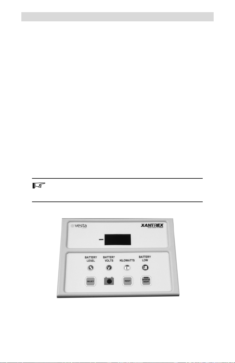
Figure 1-1
The VO-DPM
1
Page 8
2.0 CONFIGURATION
Setup
The VO-DPM is configured at the factory for monitoring a 24 VDC
system. These settings can be changed to meet specific system parameters.
The default settings are:
Charge Efficiency 94 %
%
Voltage (full-charge) 28.8 volts DC
V
KW
Amperage DC 35 amps
Amp Hours 400 Hours
LO
Low-Voltage Indicator 22.0 volts DC
Restoring the Factory Defaults
The factory defaults can be restored to their original settings if desired.
The default values will return to those listed above and are for a 24 VDC
system.
To restore the factory defaults:
1. Set the VO-DPM into the power saving mode by repeatedly pressing
the SELECT button until the LED display goes blank.
2. Press and hold the RESET button. The display will indicate ALL
flashing in the display. Continue to hold the RESET button until the LED
display remains blank.
The factory defaults are now restored.
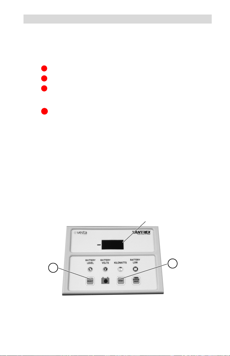
Step 2 = ALL then blank
ALL
1
Figure 2-1
Resetting to Factory Defaults
2 © 2001 Xantrex Technology Inc.
2
Page 9
2.0 CONFIGURATION
Setting Parameters
Individual system parameters can be set by the following procedure:
1. Press the SELECT button until the mode selection indicator to be set is
illuminated.
2. Press the SELECT and RESET buttons simulataniously. Release both
buttons when the LED display flashes.
3. Press and release the RESET button to scroll through the selections (or
values) slowly, or hold the RESET button to scroll rapidly.
4. When the desired value is shown in the LED display, press the SELECT
button to accept it.
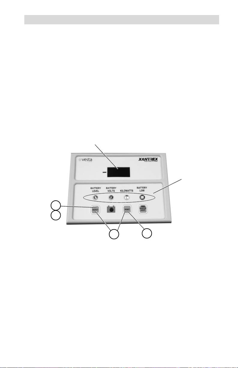
Select Value
28.8
1
4
2
Figure 2-2
Setting Parameters
© 2001 Xantrex Technology Inc. 3
3
Mode Indicators
Page 10
2.0 CONFIGURATION
Setting Parameters (continued)
Charge Efficiency
Since batteries are not 100 percent efficient, more energy is required to
charge them than can be extracted. Some of this energy is lost in the form of
heat and gassing. An efficiency factor of 94 to 98% is typical for lead-acid
batteries. Consult the battery manufacturers specifications for other
batterytypes.
Set this value to 96% for new batteries and 94% (or lower) for batteries
already in service. The default setting is 94%. Changing this setting affects
the % State-of-Charge meter. The setting range is from 60 to 100%.
%
Setting the Charge Efficiency Factor
If the charge efficiency factor is not known and lead-acid batteries are
used in the system, set the charge efficiency factor to 94%. After the
batteries have been discharged and then fully recharged, the battery level
reading should be approximately full. If this reading is less than full when the
CHARGED LED ( ) flashes, increase the efficiency factor. If the battery
level is full before the CHARGED LED flashes, decrease the efficiency factor.
The setting is correct when the CHARGED LED flashes and the battery
level% is full.
1. Press the SELECT button until the BATTERY LEVEL LED (%) is
illuminated.
2. Press the SELECT and RESET buttons simulataniously until the LED
display flashes.
3. Press the RESET button to change the displayed efficiency factor.
4. Press the SELECT button to accept the value.
Set Battery Efficiency
% LED Indicates
Efficiency Function
1
4
Setting Charger Efficiency
4 © 2001 Xantrex Technology Inc.
94
2
Figure 2-3
3
Factor in Display
Page 11

2.0 CONFIGURATION
Setting Parameters (continued)
Amp Hours
The amp-hour setting should be set to a value equal or lower than the
actual amp-hour capacity of the systems battery bank. Using a number that
is lower than the actual amp-hour capacity allows the % Battery State-ofCharge meter to provide a more conservative indication for the use of the
batteries to avoid excessively discharging them.
Also note the temperature at which the battery capacity is rated. The
amp-hour capacity of the batteries decreases at temperatures lower than the
rated value.
The amp-hour rating is usually printed on the batterys label. If the
system contains batteries in parallel, then the amp-hour rating of the parallel
batteries is added together (i.e., two 120 amp-hour rated batteries in parallel
equals 240 amp hours). The amp-hour capacity of a bank does not increase
for series-wired batteries and is equal to the lowest rated battery in the
series string. If the amp-hour capacity is not listed on the battery, consult the
battery manufacturer or dealer for assistance.
Setting the Amp Hours
1. Press the SELECT button until no LED is illuminated.
2. Press the SELECT and RESET buttons simulataniously until the LED
display flashes.
3. Press the RESET button to change the displayed amp hours to a value
slightly lower than the systems total battery amp-hour capacity.
4. Press the SELECT button to accept the new value. The selection range
is between 0 (000) to 2,550 (2.55) Ah.
NOTE: When the flashing display indicates between 000 to 990.
(decimal point after the right most digit), read the display directly.
When the flashing display indicates between 1.00 to 2.55 (decimal
point two places to the left), multiply the reading by 1000 (i.e., a
flashing 160. equals 160 amp hours; a flashing 1.60 in the display
equals 1,600 amp hours).
© 2001 Xantrex Technology Inc. 5
Page 12

2.0 CONFIGURATION
Setting Parameters (continued)
Set Battery Amp-Hour
280.
Rating
None of these will be
illuminated.
1
4
6 © 2001 Xantrex Technology Inc.
2
Figure 2-4
Setting the Amp Hours
3
Page 13

2.0 CONFIGURATION
Setting Parameters (continued)
CHARGED Indicator Setup
The CHARGED indicator LED can be programmed to light when the
batteries are fully charged based on several different parameters:
Trigger the LED when voltage only parameters are met
Trigger the LED when voltage and current parameters are met
Trigger the LED when voltage and time parameters are met
Trigger on Voltage Only
When the VO-DPM is setup to trigger on voltage only, the CHARGED LED
illuminates when the voltage reaches the level programmed into the VO-DPM.
NOTE: This mode must be setup first before setting the Voltage and
Current or Voltage and Time modes.
Step A Setting the Fully-Charged Voltage Level
1A. Press the SELECT button until the Voltage LED (V) is illuminated.
2A. Press the SELECT and RESET buttons simulataniously until the LED
display flashes.
3A. Press the RESET button to change the displayed voltage to the
desired fully-charged voltage level:
For a 12 VDC system, set this voltage between 14.314.9 volts for
lead-acid batteries.
For a 24 VDC system, set this voltage between 28.629.6 volts for
lead-acid batteries.
For a 48 VDC system, set this voltage between 57.259.2 volts for
lead-acid batteries.
Refer to the battery manufacturers recommendation for other types
of batteries.
4A. Press the SELECT button to accept the new value. The selection
range is between 10 to 64.9 VDC.
5A. Proceed to Step B.
NOTE: In 48 VDC systems, the fully charged voltage level must be
set above 35 VDC or the voltage displayed will be half.
© 2001 Xantrex Technology Inc. 7
Page 14

2.0 CONFIGURATION
Setting Parameters (continued)
CHARGED Indicator Setup (continued)
Set Voltage Level
28.8
1A
2A
4A
Setting the CHARGED Indicator Voltage Level
The fully-charged voltage parameters are now set. To allow the voltage
only setting to trigger the fully-charged LED, the amperage setting must be
switched OFF.
Step B Switching OFF the Amperage Detection
1B. Press the SELECT button until the KILOWATTS LED (KW) is illuminated.
2B. Press the SELECT and RESET buttons simulataniously until the LED
display flashes.
3B. Press the RESET button until the display indicates OFF.
4B. Press SELECT button to accept.
3A
Figure 2-5
Voltage LED
Illuminates to Indicate
the Voltage Function
is Selected
The VO-DPM is now setup to trigger the CHARGED indicator LED ( )
when the voltage level equals or exceeds the value programmed in StepA.
When this voltage parameter is met, the CHARGED indicator LED flashes
approximately every four seconds.
NOTE: The CHARGED indicator remains ON (solid) even when the
batteries are discharging, until reset.
Set Amps to
OFF
OFF
1B
KILOWATTS LED
Illuminates to Indicate
the Amperage Function
is Selected
4B
3B
2B
Figure 2-6
Turn Amps OFF for VOLTAGE ONLY Detection
8 © 2001 Xantrex Technology Inc.
Page 15

2.0 CONFIGURATION
Setting Parameters (continued)
CHARGED Indicator Setup (continued)
Trigger on Voltage and Amperage
When this mode is selected, the CHARGED indicator LED illuminates
when the voltage reaches the programmed level (Step A) and the amperage
decreases to the value set in Step B.
As batteries charge, their voltage slowly increases and the charging
current decreases. Setting these parameters allows the CHARGED indicator
LED to illuminate when specified conditions are met. However, if a
sufficiently high amperage is being drawn from DC loads during charging, the
meter detects this current, and it prevents the VO-DPM from illuminating the
CHARGED indicator LED. To set the meter to illuminate the CHARGED LED, the
amperage trigger level must be increased to account for the additional
DCloads.
NOTE: The batteries may not be fully charged if DC loads are in the
system and the current level is increased.
To determine the appropriate fully charged amperage for the system,
divide the battery bank amp-hour capacity by 20. For example; if the battery
banks amp-hour rating equals 880 amp hours, divide this value by 20 for an
amperage setting of 44 amps.
Step A Setting the Fully-Charged Voltage Level
1A. Press the SELECT button until the Voltage LED (V) is illuminated.
2A. Press the SELECT and RESET buttons simulataniously until the LED
display flashes.
3A. Press the RESET button to change the displayed voltage to the
desired fully charged voltage level:
For a 12 VDC system, set this voltage between 14.314.9 volts for
lead-acid batteries.
For a 24 VDC system, set this voltage between 28.629.6 volts for
lead-acid batteries.
For a 48 VDC system, set this voltage between 57.259.2 volts for
lead-acid batteries.
Refer to the battery manufacturers recommendation for other types
of batteries.
4A. Press the SELECT button to accept the new value. The selection
range is between 10 to 64.9 VDC.
© 2001 Xantrex Technology Inc. 9
Page 16

2.0 CONFIGURATION
Setting Parameters (continued)
CHARGED Indicator Setup
1A
(continued)
28.8
Set Voltage Level
Voltage LED
Illuminates to Indicate
the Voltage Function
is Selected
4A
2A
3A
Figure 2-7
Setting the CHARGED Indicator Voltage Level
Step B Setting the Amperage Trigger Level
1B. Press the SELECT button until the KILOWATTS LED (KW) is illuminated.
2B. Press the SELECT and RESET buttons simulataniously until the LED
display flashes.
3B. Press the RESET button until the display indicates the desired
amperage.
4B. Press SELECT button to accept.
The selectable amperage values are from 1 to 99 amps.
The VO-DPM is now setup to trigger the CHARGED indicator LED ( )
when the voltage level equals or exceeds the value programmed in StepA
and the amperage level falls below the value programmed in Step B. When
these parameters are met, the CHARGED indicator LED flashes approximately
every four seconds. Whenever the kilowatts/power goes negative
(discharge) the CHARGED LED goes solid and battery level is set to full. The
CHARGED indicator must be manually reset to turn itOFF. To turn OFF the
CHARGED INDICATOR, press reset while the %, KW, or V LED is ON.
Set Amperage
1B
4B
2B
44A
3B
Kilowatts LED Illuminates
to Indicate the Amperage
Function is Selected
Figure 2-8
Trigger on Voltage and Amperage
10 © 2001 Xantrex Technology Inc.
Page 17

2.0 CONFIGURATION
Setting Parameters (continued)
CHARGED Indicator Setup (continued)
Trigger on Voltage and Time
When this mode is selected, the CHARGED indicator LED illuminates
when the voltage reaches the programmed level (Step A) and the kilowatts/
power remains positive for the specified time (Step B).
Step A Setting the Fully-Charged Voltage Level
1A. Press the SELECT button until the Voltage LED (V) is illuminated.
2A. Press the SELECT and RESET buttons simulataniously until the LED
display flashes.
3A. Press the RESET button to change the displayed voltage to the
desired fully charged voltage level.
For a 12 VDC system, set this voltage between 14.314.9 volts for
lead-acid batteries.
For a 24 VDC system, set this voltage between 28.629.6 volts for
lead-acid batteries.
For a 48 VDC system, set this voltage between 57.259.2 volts for
lead-acid batteries.
Refer to the battery manufacturers recommendation for other types
ofbatteries.
4A. Press the SELECT button to accept the new value.
The selection range is between 10 to 64.9 VDC.
5A. Proceed to Step B.
Set Voltage Level
28.8
1A
4A
2A
3A
Setting the CHARGED Indicator Voltage Level
© 2001 Xantrex Technology Inc. 11
Figure 2-9
Voltage LED Illuminates
to Indicate the Voltage
Function is Selected
Page 18

2.0 CONFIGURATION
Setting Parameters (continued)
CHARGED Indicator Setup (continued)
Step B Setting the Time Duration
1B. Press the SELECT button until the KILOWATTS LED (
KW
) is illuminated.
2B. Press the SELECT and RESET buttons simulataniously until the LED
display flashes.
3B. Press the RESET button until the display reaches the hour settings.
These selections are available following the amperage settings.
Select the desired time (in hours or tenths of hours); the voltage must
remain at this level to trigger the CHARGED LED.
4B. Press SELECT button to accept. The selectable amperage values are
from 0.2H to 2.0H (12 minutes to 2 hours).
The VO-DPM is now setup to trigger the CHARGED indicator LED ( )
when the voltage level equals or exceeds the value programmed in StepA
and the kilowatts/power remains positive for the time duration programmed in
Step B. When these parameters are met, the CHARGED indicator LED flashes
approximately every four seconds. Whenever the kilowatts/power goes
negative (discharging), the CHARGED LED goes solid and battery level to
FULL. The CHARGED indicator LED must be manually reset to turn it OFF. To
turn off the CHARGED indicator, press reset while the %, KW, or V LED
ison.
Set Time Duration
1. H
1B
Kilowatts LED
Illuminates to
Indicate the
Amperage
Function is
Selected
4B
2B
3B
Figure 2-10
Trigger on Voltage and Time
12 © 2001 Xantrex Technology Inc.
Page 19

2.0 CONFIGURATION
Setting Parameters (continued)
CHARGED Indicator Setup (continued)
Charger Considerations
There are several different types of chargers (relay, taper or threestage) which can affect the settings and prevent the CHARGE LED from
illuminating.
Relay Chargers
Relay type chargers raise the battery to a set voltage level then shut
OFF using only voltage as their parameter. Set the VO-DPM to the
voltage only mode and set the voltage slightly below the charger turnoff
setting.
Taper Chargers
Taper type chargers raise the battery to a specified voltage and shut
OFF when the amperage decreases to a specified level. When using
taper type chargers (pulse-width-modulated), set the voltage and taper
amperage parameters slightly below that of the charger.
If the taper charger is a type that charges up to a certain level and then
waits for a period of time to determine if the batteries are charged, then
set the VO-DPM to a voltage slightly below the chargers settings. Set the
time a little shorter than the chargers time period.
Three-stage Chargers
Three-stage chargers raise the battery to a specified voltage level and
then maintain the batteries at a Float voltage and trickle current. Adjust
the VO-DPM s voltage parameters slightly above the chargers float
voltage setting. Set the amperage slightly below the chargers float
amperage setting.
© 2001 Xantrex Technology Inc. 13
Page 20

2.0 CONFIGURATION
Setting Parameters (continued)
Low-Voltage Indicator
The VO-DPM should be set to trigger on a user specified low DC voltage
level. When the battery voltage falls below this level, the BATTERY LOW LED
LO
(
) will illuminate. This meter is useful to determine if the batteries are being
over-discharged. Refer to the battery manufacturers specifications for the
proper low-voltage level.
A voltage between 10 and 35 volts (10 and 64.9 volts for 48-volt
systems) can be specified to activate the low-voltage alarm.
LO
Configuring the Low-Voltage Alarm
1. Press and hold the SELECT button until the cAH message is displayed,
then release.
2. Press and release the SELECT button until the bLO message is
displayed in the LED display.
3. Press and release the SELECT and RESET button simultaneously.
4. Press the RESET button until the desired voltage level is displayed.
5. Press the SELECT button to accept this value.
6. Press the SELECT button to return to the metering mode.
Step 1 = dSF
Step 2 = bLO
Step 4 = value
cAH
1
2
5
6
Low-Voltage Indicator
14 © 2001 Xantrex Technology Inc.
3
Figure 2-11
4
Page 21

3.0 OPERATION
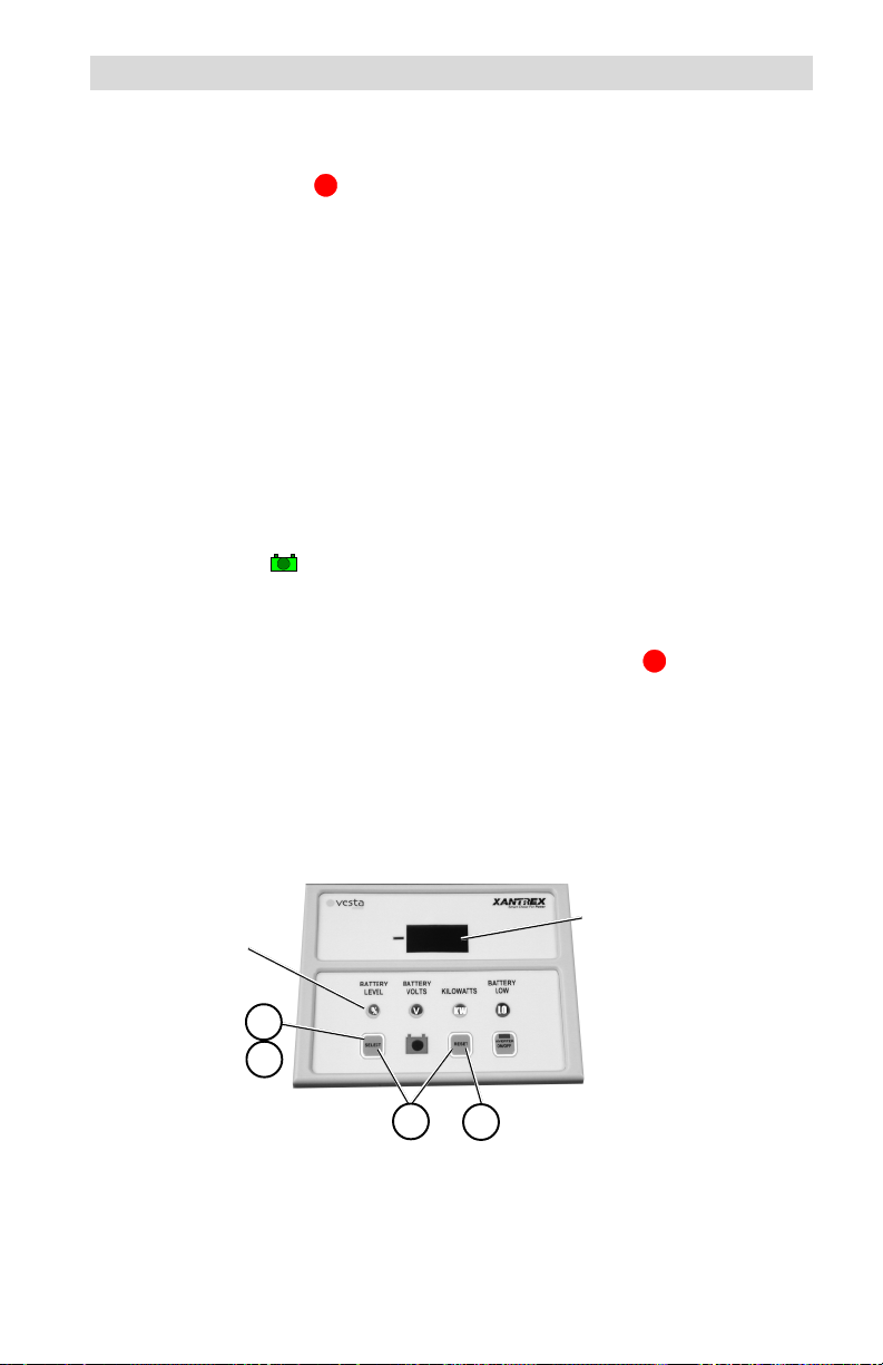
Indicators and Controls
The VO-DPM contains the following controls and indicators.
Large three-digit LED display
Three yellow mode indicators
One red alarm indicator
One green CHARGED indicator
One green INVERTER ON/OFF indicator
Three pressure sensitive push-buttons
The three-digit LED displays alphanumeric messages with a resolution to
0.00. A negative value () indicator is positioned to the left of the display.
Negative
Value
Indicator
Select
CHARGED
Indicator
Reset Button
3-digit
Display
Mode
Indicators
Inverter Mode LED
(on Button)
Inverter
ON/OFF
Button
Figure 3-1
Front Panel Controls and Indicators
Buttons
SELECT Button
The SELECT button is used to switch the VO-DPM between the
different meters and modes. One of the LEDs located above the
buttons illuminate, indicating the active function.
RESET Button
The RESET button is used to change the metering parameters and to
reset the CHARGED indicator.
INVERTER ON/OFF Button (DR Inverter units only)
The INVERTER ON/OFF button remotely controls the inverters ON/
OFF function via the RC4 or RC8 remote control jack. This button
duplicates the function of the inverters power switch. The LED
duplicates the indications of the RC8 remote control. Refer to the RC4/
RC8 documentation (supplied with the cable) for LED indications and
modes available (depends on inverter). Remote control cables are
available in 10, 25, 50 and 100 foot lengths. This button/LED does not
function if a remote control cable is not connected or if the inverter does
not support an RC4 or RC8 remote control. To use this function, the RC8
on the Vesta Power Module must be disconnected from the DR inverter.
© 2001 Xantrex Technology Inc. 15
Page 22

3.0 OPERATION
Indicators and Controls (continued)
Basic Meters
To display one of the four meters;
Press the SELECT button until the desired indicator illuminates.
The LED display indicates the values for the selected function.
Value for selected
Polarity Indicator
mode appears in
the display
12.4
Press SELECT until the desired function
LED illuminates
Meter Selection and LED Indicators
Figure 3-2
Available Meters
BATTERY LEVEL
When this indicator is illuminated, the LED display shows the batterys
state-of-charge based upon the amp-hour capacity of the batteries (or
battery bank). The values displayed are:
LO (when battery is below 27.5%)
30 to 90% numerical value (in 5% increments)
FULL when the batterys state-of-charge is over 92.5% capacity
BATTERY VOLTS
When this indicator is illuminated, the LED display shows the real time
voltage from 08.0 to 35 volts (for 12- to 24-volt systems) ±0.1 volt
accuracy, or 16.0 to 69.9 volts (for 48-volt systems) ±0.2 volt accuracy.
KILOWATTS
When this indicator is illuminated, the LED display shows the
approximate real-time charge or load. The range is from ±0.01 to
±9.99kW.
16 © 2001 Xantrex Technology Inc.
%
V
KW
Page 23

3.0 OPERATION
Indicators and Controls (continued)
BATTERY LOW
When this indicator is illuminated, either the BATT% is less than or equal
to 50% or the battery volts are less than the low battery setpoint.
Battery Voltage Indicator
Battery Level
Kilowatts
Battery Low
Full
Figure 3-3
Mode Indicator LEDs
Power Saving Mode
The VO-DPM can be put into a low-power/power-saving mode by
repeatedly pressing the SELECT button until the display goes blank. In this
mode, none of the LED indicators illuminate. The power consumption of the
unit is reduced from 32 mA maximum to approximately 18 mA. Pressing the
SELECT button again exits the power-saving mode.
© 2001 Xantrex Technology Inc. 17
Page 24

3.0 OPERATION
Indicators and Controls (continued)
Data Monitors
There are several additional data displays available, accessed by
pressing and holding the SELECT button until cAH appears in the display.
Pressing and releasing the SELECT button alternates between its value, then
scrolls to the next menu item. The data types will alternate with the data
values.
The available data monitor functions are:
cAH (Cumulative Amp Hours)
This meter measures the cumulative amp hours used from the batteries.
This function can be used as a battery life indicator. The range is from
00.0 to 999,000. Multiply the displayed value by 1000 when the decimal
point flashes. The cumulative value remains in memory even if the VO-
DPM is disconnected. This meter can be manually reset to zero.
bHI (High Battery Voltage)
This meter displays the highest battery voltage detected. Use this meter
to determine if an overvoltage condition occurred or that the charging
sources are charging to the voltage setting of the charger. The meter
resets to the current battery voltage value when it is disconnected and
reconnected to the DC shunt or is manually reset.
bLO (Low Battery Voltage)
This meter displays the lowest battery voltage detected. Use this meter
to determine if the batteries are being over-discharged. This meter resets
to the current battery voltage value when the RESET button is pressed
and must be manually reconfigured after the DC power is cycled or when
first installed.
To access the Data Monitor Function:
Press and hold the SELECT button until cAH appears in the LED display.
The display alternates between the data monitor function and its data.
Continue pressing the SELECT button to scroll through all the available
displays and their data.
When the bLO data has been accessed, another press of the SELECT
button returns to the basic meters function.
To reset the data monitor values to zero (or the present value) press and
hold the RESET button for approximately 5 seconds (the data monitor value
flashes three times and then updates).
18 © 2001 Xantrex Technology Inc.
Page 25

4.0 TROUBLESHOOTING
motpmyS esuaCelbissoP noituloS
FFO/NORETREVNIniDEL
.thgiltonseodhctiws
nodeyalpsidegatloV
.tcerroctonsisretem
egrahC-fo-etatSyrettaB
nehw"LLUF"syalpsid
.wolsiegatlov
.0.00
foegatlovasyalpsidOLb
seunitnocDELDEGRAHC
ehthguohtnevehsalfot
evitagensiwolfrewop
)gnigrahcsidyrettab(
.etunimenorofylsuounitnoc
).ylnoretrevni
otnideggulptongulp2J
RD(.retrevnIroMPD-OV
aevahtonseodretrevnI
.kcaJelbatapmoc
siegatlovMPD-OVehT
stlov0.53evobaderugifnoc
.metsystlov42ro21arof
siegatlovMPD-OVehT
stlov0.53wolebderugifnoc
.metsystlov84arof
.wolootsignittesruoh-pmAotsruohpmaehterugifnoceR
tonsawretemOLbehT
ro,pu-tesgnirudderugifnoc
detcennocsidgniebretfa
.tnuhsehtmorf
YLNOEGATLOV
ehtrofnoitarugifnoc
puteSrotacidnIdegrahC
.woloottesebyam
.kcajlortnoc
.sretrevni
,2noitceSees(
.)pu-teSrotacidnI
.ezisknab
.)metsystlov-21
dnaMPD-OVotnielbacgulP
etomer8CR/4CRs'retrevnI
lortnocetomerretrevniehT
RDehtnosetarepoylno
rofMPD-OVehterugifnoceR
egatlovmetsystcerroceht
degrahC,noitarugifnoC
yrettaB-gnittestcerroceht
egatloVwoLehterugifnoceR
tcerrocehtrof)OLb(rotacidnI
.egatlovyrettab-wol
DEGRAHCehterugifnoceR
etairporppanaotegatlov
arofstlov6.21,.e.i(eulav
rotacidniDEGRAHCehT
nrutotteseryllaunamebtsum
.01egapeeS.FFOti
© 2001 Xantrex Technology Inc. 19
Page 26

5.0 SERVICE INFORMATION
Xantrex Technology Inc., takes great pride in its products and makes
every effort to ensure your unit fully meets your independent powering needs.
If your product needs repair, contact our Customer Service department at:
(360) 435-8826 to obtain an RMA# and shipping information; or, fax this page
with the following information to: (360) 474-0616. Or contact the Xantrex
Warranty Department at Tracewarranty@traceengineering.com.
Please provide:
Model Number: _________________________________
Serial Number: _________________________________
Purchase Date: _________________________________
Problem: ______________________________________
Include a telephone number where you can be reached during business
hours and a complete return shipping address (P.O. Box numbers are not
acceptable).
Name: __________________________________________
Address: ________________________________________
City: ___________________________________________
State / Province: __________________________________
Zip / Postal Code: _________________________________
Country: ________________________________________
Phone: (____) ____________________________________
FAX: (____)______________________________________
E-mail Address: __________________________________
5916 - 195th Street N.E., Arlington, WA 98223 Phone: (360) 435-8826 Fax: (360) 435-2229
visit our website at: www.xantrex.com
20 © 2001 Xantrex Technology Inc.
Page 27

6.0 SPECIFICATIONS
Specifications
Function Range Accuracy
Battery Volts 8.035 volts ± 0.1 volt
Kilowatts 0.19.99 kW (approximate)
Battery Level % Low (< 27.5%) ~ 2.5% accuracy
Current Draw
Power Saving Mode 18 mA maximum
All other modes 32 mA maximum
Battery Capacity 10 to 2550 amp hours
Data Monitoring Functions
cAHCumulative Ah Removed 0999,000 in nonvolatile memory
bHIBattery High Volts to 35.1 VDC resettable (1224 VDC)
bLOBattery Low Volts 8.0 volts, resettable (1224 VDC)
LED Display 3-digit, 7-segment red LED
LED Indicators
Dimensions 3-7/8" H x 5-3/8" W x 1-1/4" D
16.070 volts ± 0.2 volt
3090% in 5% increments
FULL (> 92.5%)
to 70.2 VDC (w/optional 48 VDC adaptor)
16.0 volts, resettable (w/48 VDC adaptor)
with 5 additional indicators
State of Charge(SOC)/Battery Efficiency
Battery Voltage
Kilowatts
Low Battery Voltage (adjustable)
(14 cm H x 9.5 cm W x 3.2 cm D)
Weight approximately 3 lb (1.36 kg)
Specifications @ 25 °C.
Specifications subject to change without notice.
©2001 Xantrex Technology Inc. 21
Page 28

7.0 WARRANTY
Limited Warranty
Xantrex warrants its Vesta electrical power products against defects in
materials and workmanship for a period of one (1) year from the date of
purchase, established by proof of purchase or formal warranty registration, and
extends this warranty to all purchasers or owners of the product during the
warranty period. The XS series batteries are covered by a separate battery
warranty described in the XS installation guide. Xantrex does not warrant its
products from any and all defects:
arising out of material or workmanship not provided by Xantrex or its
Authorized Service Centers;
when the product is installed or exposed to an unsuitable environment as
evidenced by generalized corrosion or biological infestation;
resulting from abnormal use of the product, alteration or use in violation of
the instructions;
in components, parts or products expressly warranted by another manufac-
turer.
Xantrex agrees to supply all parts and labor to repair or replace defects
covered by this warranty with parts or products of original or improved design,
at the company's option. Xantrex also reserves the right to improve the design
of its products without obligation to modify or upgrade those previously
manufactured. Defective products must be returned to Xantrex or its Authorized Service Center in the original packaging or equivalent. The cost of
transportation and insurance on items returned for service is the responsibility
of the customer. Return transportation (UPS Ground or equivalent) as well as
insurance on all repaired items is paid by Xantrex.
All remedies and the measure of damages are limited to the above.
Xantrex shall in no event be liable for consequential, incidental, contingent or
special damages, even if Xantrex has been advised of the possibility of such
damages. Any and all other warranties, expressed or implied, arising by law,
course of dealing, course of performance, usage of trade or otherwise,
including, but not limited to, implied warranties of merchantability and fitness
for a particular purpose, are limited in duration for a period of one (1) year from
the original date of purchase.
Some states or counties do not allow limitations on the term of an implied
warranty, or the exclusion or limitation of incidental or consequential damage,
which means the limitations and exclusions of this warranty may not apply to
you. Even though this warranty gives you specific legal rights, you may also
have other rights which vary from state to state.
5916 - 195th Street N.E., Arlington, WA 98223 Phone: (360) 435-8826 Fax: (360) 435-2229
visit our website at: www.xantrex.com
22 © 2001 Xantrex Technology Inc.
Page 29

Page 30

Page 31

Page 32

Xantrex Technology Inc.
5916 195th Northeast
Arlington, WA 98223
U.S.A.
t: 360/435.8826
f: 360/435.3945
www.xantrex.com Printed in U.S.A.
© 2001 Xantrex Technology Inc.
P/N 975-0020-01-01 Rev. A 07/01
 Loading...