

Xantrex Truecharge TC1512, Truecharge TC5012, Truecharge TC2012, Truecharge TC3012, Truecharge TC6012 Installation Manual
...Page 1
TC1012
10A–12V
TC1512
TC2012
TC3012
TC4012
TC5012
TC6012
TC1524
TC2024
TC3024
TC5024
15A–12V
20A–12V
30A–12V
40A–12V
50A–12V
60A–12V
15A–24V
20A–24V
30A–24V
50A–24V
Installation Guide
Series Battery Charger
This guide for use by qualified installers only
Page 2

Page 3

™
Truecharge
2
Series Battery
Chargers
Installation Guide
This guide for use by qualified installers only
Page 4

About Xantrex
Xantrex Technology Inc. is a world-leading supplier of advanced power electronics and
controls with products ranging from small mobile units to utility-scale systems for wind,
solar, batteries, fuel cells, microturbines, and backup power applications in both gridconnected and stand-alone systems. Xantrex products inclu de inverters, battery chargers,
programmable power supplies, and variable speed drives that convert, supply, control,
clean, and distribute electrical power.
Trademarks
Truecharge™ 2 Series Battery Char ger is a tr ademark of Xantrex I nternational. Xantrex is
a registered trademark of Xantrex International.
Other trademarks, registered trademarks, and product names are the property of their
respective owners and are used herein for identification purposes only.
Notice of Copyright
Truecharge™ 2 Series Battery Charger Installation Guide © June 2008 Xantrex
International. All rights reserved.
Exclusion for Documentation
UNLESS SPECIFICALLY AGREED TO IN WRITING, XANTREX TECHNOLOGY INC.
(“XANTREX™”)
(
A) MAKES NO WARRANTY AS TO THE ACCURACY, SUFFICIENCY OR SUITABILITY OF ANY
TECHNICAL OR OTHER INFORMATION PROVIDED IN ITS MANUALS OR OTHER
DOCUMENTATION.
(
B) ASSUMES NO RESPONSIBILITY OR LIABILITY FOR LOSSES, DAMAGES, COSTS OR
EXPENSES, WHETHER SPECIAL, DIRECT, INDIRECT, CONSEQUENTIAL OR INCIDENTAL,
WHICH MIGHT ARISE OUT OF THE USE OF SUCH INFORMATION. THE USE OF ANY SUCH
INFORMATION WILL BE ENTIRELY AT THE USER’S RISK; AND
(C) REMINDS YOU THAT IF THIS MANUAL IS IN ANY LANGUAGE OTHER THAN ENGLISH,
ALTHOUGH STEPS HAVE BEEN TAKEN TO MAINTAIN THE ACCURACY OF THE TRANSLATION,
THE ACCURACY CANNOT BE GUARANTEED. APPROVED XANTREX CONTENT IS CONTAINED
WITH THE ENGLISH LANGUAGE VERSION WHICH IS POSTED AT WWW.XANTREX.COM.
Date and Revision
June 2008 Rev A
Part Number
975-0402-01-01
Product Numbers
804-1210, 804-1215, 804-1220, 804-1230, 804-1240, 804-1250, 804-1260, 804-2415,
804-2420, 804-2430, 804-2450
Contact Information
Telephone: 1 800 670 0707 (toll free North America)
1 408 987 6030 (direct)
+34 93 470 5330 (Europe)
Fax: 1 800 994 7828 (toll free North America)
+34 93 473 6093 (Europe)
Email: customerservice@xantrex.com
Web: www.xantrex.com
This guide for use by qualified installers only
Page 5

About This Guide
Purpose
The purpose of this Installation Guide is to provide
explanations and procedures for installing and configuring
the Truecharge™ 2 Series Battery Charger.
Scope
The Guide provides safety guidelines, procedures for
installing the battery charger, as well as information on
configuring the battery charger. It does not provide details
about particular brands of batteries. You need to consult
individual battery manufacturers for this information.
Refer to Truecharge™ 2 Battery Charger Owner’s Guide
(doc. part number: 975-0401-01-01) for operational
instructions.
Audience
The Guide is intended for qualified installers who need to
install and configure any model unit of the Truecharge™ 2
Series Battery Charger. The installer should be a qualified
technician or electrician.
Organization
This Guide is organized into two chapters and one appendix.
Chapter 1 describes the standard features of a Truecharge™ 2
Battery Charger, as well as its protection features. It also
provides information on the different parts of the
Truechar ge™ 2 Battery Char ger including information on the
optional remote panel.
This guide for use by qualified installers only
iii
Page 6

About This Guide
Chapter 2 provides procedures for installing, testing and
configuring the Truecharge™ 2 Battery Charger.
Appendix A contains physical, electrical performance, and
regulatory approval specifications for the Truecharge™ 2
Battery Charger.
Conventions Used
The following conventions are used in this guide.
WARNING
Warnings identify conditions or practices that could result in
personal injury or loss of life.
CAUTION
Cautions identify conditions or practices that could result in
damage to the unit or other equipment.
Important:
for you to know, but not as serious as a caution or warning.
This Guide contains information for 11 product models of the
Truecharge™ 2 Series Battery Charger.
The 12V models are: TC1012, TC1512, TC2012, TC3012,
TC4012, TC5012, and TC6012. When being refe rred to
individually, the product will be referred to by its model
name.
The 24V models are: TC1524, TC2024, TC3024, and
TC5024. When being referred to individually, the product
will be referred to by its model name.
When all models are being referred to, they will be referred to
as Truecharge™ 2 Battery Chargers.
These notes describe things which are important
Related Information
You can find more information about Xantrex Technology
Inc. as well as its products and services at www.xantrex.com
iv 975-0402-01-01
This guide for use by qualified installers only
Page 7

Important Safety Instructions
READ AND SAVE THIS INSTALLATION GUIDE FOR FUTURE
REFERENCE.
This chapter contains important safety, installation, and
operating instructions for the Truecharge™ 2 Series Battery
Chargers.
1. Before installing and using a Truecharge™ 2 Battery
Charger, read all instructions and cautionary markings on
a Truecharge™ 2 Battery Charger unit, the batteries, and
all appropriate sections of this guide.
CAUTION: Risk of injury
T o reduce the risk of injury, charge only properly rated (such as
12 V and 24 V) lead-acid (GEL, AGM, Flooded, or leadcalcium) rechargeable batteries. Other battery types may burst,
causing personal injury and damage.
2. Do not expose the Truecharge™ 2 Battery Charger to
rain, snow, spray, or bilge water. To reduce risk of fire
hazard, do not cover or obstruct the air intake vent
openings. Do not install the Truecharge™ 2 Battery
Charger in a zero-clearance compartment. Overheating
may result.
3. This appliance is not intended for use by persons
(including children) with reduced physical, sensory, or
mental capabilities or lack of experience and knowledge,
unless they have been given supervision or instruction
concerning use of the appliance by a person responsible
for their safety. Children should be supervised to ensure
that they do not play with the appliance.
This guide for use by qualified installers only
v
Page 8

Safety
4. To avoid a risk of fire and electric shock, make sure that
existing wiring is in good condition and that wire is not
undersized. Do not operate the Truecharge™ 2 Battery
Charger with damaged or substandard wiring.
5. The use of any attachments not recommended or sold by
Xantrex, may result in risk of fire, electric shock, or
injury to persons.
6. Do not operate the Truecharge™ 2 Battery Charger if it
has received a sharp blow, been dropped, has cracks or
openings in the enclosure (especially when the fuse cover
has been damaged and will not close), or otherwise
damaged in any other way. If the Truecharge™ 2 Battery
Charger is damaged, see the Warranty section.
7. Do not disassemble the Truecharge™ 2 Battery
Charger—there are hazardous voltages within. It contains
no user-serviceable parts. See Warranty for instructions
on obtaining service. Attempting to service the
Truecharge™ 2 Battery Charger yourself may result in a
risk of electrical shock or fire and will void your
warranty. Internal capacitors remain charged after all
power is disconnected.
8. To reduce the risk of electrical shock, disconnect both
AC and DC power from the Truecharge™ 2 Battery
Charger before attempting any maintenance or cleaning
or working on any circuits connected to the T ruecharge™
2 Battery Charger. Turning off using the on/standby
button on the remote panel will not reduce this risk.
9. The Truecharge™ 2 Battery Charger must be provided
with equipment-grounding conductors connected to the
AC and input ground, and from chassis to the DC ground.
vi 975-0402-01-01
This guide for use by qualified installers only
Page 9

WARNING: Explosion hazard
10. Working in the vicinity of lead-acid batteries is
dangerous. Batteries generate explosive gase s during
normal operation. Therefore, it is of utmost importance
that each time before servicing the charger in the vicinity
of the battery, that you read this manual and follow the
instructions exactly.
11. To reduce the risk of battery explosion, follow these
instructions and those published by the battery
manufacturer and the manufacturer of any unit yo u
intend to use in the vicinity of the battery. Review
cautionary markings on these products and on the engine
Safety
Personal Precautions When Working With
Batteries
WARNING: B
LECTRICAL SHOCK
E
IRCUIT CURRENT
C
ENTED GASES
V
1. Have someone within range of your voice or close
enough to come to your aid when you work near a lead acid battery.
2. Have plenty of fresh water and soap nearby in case
battery acid contacts skin, clothing, or eyes.
3. Wear proper, non-absorbent gloves, complete eye
protection, and clothing protection. Avoid touching your
eyes and wiping your forehead while working near
batteries.
ATTERIES PRESENT RISK OF
, B
URN FROM HIGH SHORT
, F
IRE OR EXPLOSION FROM
. O
BSERVE PROPER PRECAUTIONS
-
.
975-0402-01-01 vii
This guide for use by qualified installers only
Page 10

Safety
4. If battery acid contacts skin or clothing, wash
immediately with soap and water. If acid enters yo ur eye,
immediately flood it with running cold water for at least
twenty minutes and get medical attention immediately.
5. Never smoke or allow a spark or flame near the engine or
batteries.
6. Use extra caution to reduce the risk or dropping a metal
tool on the battery. It could spark or short circuit the
battery or other electrical parts and could cause an
explosion.
7. Remove all personal metal items, like rings, bracelets,
and watches when working with batteries. Batteries can
produce a short circuit current high enough to weld metal
to skin, causing a severe burn.
8. If you need to remove a battery, always remove the
ground terminal from the battery first. Make sure all
accessories are off so you don’t cause an arc.
9. Never charge a frozen battery.
PREPARING TO CHARGE
10. Make sure the area around the battery is well ventilated.
11. Make sure the voltage of the batteries matches the output
voltage of the battery charger.
12. Clean battery terminals. Be careful to keep corrosion
from coming into contact with your eyes and skin.
13. Study and follow all of the battery manufacturer's
specific precautions, such as removing or not removing
cell caps while charging, whether equalization is
acceptable for your battery, and recommended rates of
charge.
14. Add distilled water in each cell until battery acid reaches
the level specified by the battery manufacturer. This
helps to purge excessive gas from cells. Do not overfill.
For a battery without removable cell caps, carefully
follow manufacturer's instructions.
viii 975-0402-01-01
This guide for use by qualified installers only
Page 11

BATTERY CHARGER LOCATION
15. Locate the Truecharge™ 2 Battery Charger unit away
from batteries as practical in a well ventilated
compartment.
16. Never place the Truecharge™ 2 Battery Charger unit
directly above batteries; gases from a battery will corrode
and damage the charger
17. Never allow battery acid to drip on the charger when
reading gravity, or filling battery.
18. Do not operate the charger in a closed in area, or restrict
the ventilation in any way.
19. Do not place a battery on top of the charger.
20. For North American marine installations, external
connections to the charger shall comply with the United
States Coast Guard Electrical Regulations (33CFR183,
Sub Part I).
Safety
975-0402-01-01 ix
This guide for use by qualified installers only
Page 12

Safety
FCC Information to the User
This equipment has been tested and found to comply with the
limits for a Class B digital device, pursuant to part 15 of the
FCC Rules. These limits are designed to provide reasonable
protection against harmful interference in a residential
installation. This equipment generates, uses, and can radiate
radio frequency energy and, if not installed and used in
accordance with the instructions, may cause harmful
interference to radio communications.
However, there is no guarantee that interference will not
occur in a particular installation. If this equipment does cause
harmful interference to radio or television reception, which
can be determined by turning the equipment off and on, the
user is encouraged to try to correct the interference by one or
more of the following measures:
• Reorient or relocate the receiving antenna.
• Increase the separation between the equipment and
receiver.
• Connect the equipment into an outlet on a circuit
different from that to which the receiver is connected.
Consult the dealer or an experienced radio/TV technician for
help.
x 975-0402-01-01
This guide for use by qualified installers only
Page 13

Contents
Important Safety Instructions
1
Introduction
Truecharge™ 2 Battery Charger - - - - - - - - - - - - - - - - - - - - - 1–1
Standard and Protection Features - - - - - - - - - - - - - - - - - - - - 1–2
Truecharge™ 2 Battery Charger - - - - - - - - - - - - - - - - - - - - - 1–4
Rear Panel- - - - - - - - - - - - - - - - - - - - - - - - - - - - - - - - - - - - 1–6
Onboard Control and Status Display Panel - - - - - - - - - - - - - - 1–8
Remote Panel (Sold Separately) - - - - - - - - - - - - - - - - - - - - -1–15
2
Installation
Preparing for Installation - - - - - - - - - - - - - - - - - - - - - - - - - - 2–2
Tools and Materials - - - - - - - - - - - - - - - - - - - - - - - - - - 2–4
Location - - - - - - - - - - - - - - - - - - - - - - - - - - - - - - - - - - 2–5
Wiring Requirements - - - - - - - - - - - - - - - - - - - - - - - - - 2–8
- - - - - - - - - - - - - - - - - - - - v
DC Wiring - - - - - - - - - - - - - - - - - - - - - - - - - - - - - 2–8
AC Wiring - - - - - - - - - - - - - - - - - - - - - - - - - - - - -2–10
Battery Bank Size Requirements - - - - - - - - - - - - - - - - -2–11
Installing the Truecharge™ 2 Battery Charger - - - - - - - - - - -2–12
Installation Sequence - - - - - - - - - - - - - - - - - - - - - - - - -2–12
Planning DC Wiring - - - - - - - - - - - - - - - - - - - - - - - - - -2–13
Planning AC Wiring - - - - - - - - - - - - - - - - - - - - - - - - - -2–15
Mounting the Truecharge™ 2 Battery Charger - - - - - - - -2–18
Make the Final Connections - - - - - - - - - - - - - - - - - - - -2–19
Installing the Drip Protection Rubber Boots - - - - - - -2–20
Final DC Connections - - - - - - - - - - - - - - - - - - - - - -2–20
Final AC Connections - - - - - - - - - - - - - - - - - - - - - -2–22
Grounding Instructions - - - - - - - - - - - - - - - - - - - - -2–23
Powering Up - - - - - - - - - - - - - - - - - - - - - - - - - - - - - - -2–23
This guide for use by qualified installers only
xi
Page 14

Contents
Installing Optional Accessories- - - - - - - - - - - - - - - - - - - - - -2–24
Mounting the Optional Remote Panel - - - - - - - - - - - - - -2–24
Installing the Optional Battery Temperature Sensor (BTS) 2–25
Configuring the Truecharge™ 2 Battery Charger- - - - - - - - - -2–26
Configuring the Charger Mode - - - - - - - - - - - - - - - - - - -2–27
Configuring the Battery Bank Type - - - - - - - - - - - - - - -2–29
Configuring the Battery Temperature without the BTS - -2–30
Configuring the Maximum Output Current Percentage - - -2–31
Installing Batteries - - - - - - - - - - - - - - - - - - - - - - - - - - - - - -2–32
A
Specifications
Physical Specifications - - - - - - - - - - - - - - - - - - - - - - - - - - - A–2
Electrical Specifications - - - - - - - - - - - - - - - - - - - - - - - - - - A–3
AC Input Specifications - - - - - - - - - - - - - - - - - - - - - - - - - - A–5
DC Output Specifications - - - - - - - - - - - - - - - - - - - - - - - - - A–6
Temperature Specifications - - - - - - - - - - - - - - - - - - - - - - - - A–6
Protection Features- - - - - - - - - - - - - - - - - - - - - - - - - - - - - - A–7
Approvals - - - - - - - - - - - - - - - - - - - - - - - - - - - - - - - - - - - - A–8
xii 975-0402-01-01
This guide for use by qualified installers only
Page 15

1
Chapter 1 describes the standard features of a
Truecharge™ 2 Battery Charger, as well as its
protection features. It also provides information on the
different parts of the Truecharge™ 2 Battery Charger
including information on the optional remote panel.
Introduction
Truecharge™ 2 Battery Charger
The Truech arge™ 2 Battery Char ger ships with the following
items.
• one Truecharge™ 2 Battery Charger unit
• installation and operation guides
• rubber boots for DC terminals
• ring terminals, nuts, and washers
• strain relief clamp for AC input cables
This guide for use by qualified installers only
Page 16

Introduction
Standard and Protection Features
The T ruecharge™ 2 Battery Charger provides the following standard
features:
•three
1
full current rated outputs
• battery monitoring functions while in float mode or rest
mode
• correct charging voltage for your batteries when
connected to almost any single phase AC power outlet in
the world
• low electromagnetic interference (EMI)
• automatic charge resumption after AC power interruption
• programmable custom charge sequence
• fully discharged battery charging
3
2
• an optional remote panel4 which can be mounted up to
15 m (50 ft) away for remote control and monitoring.
• an optional battery temperature sensor
5
(BTS) provides
battery temperature voltage compensation from -25 to
70 °C (-13 to 158 °F)
1.Model TC1012 has one output and model TC1512 has two outputs. All oth er models
have three outputs. Each output (for models with 2 or 3 outputs) can charge different batteries that either have the same chemistry or can tolerate the same charge sequence.
2.The charger can be programmed with custom charge setpoints using PC interface. This
programming can only be done using a special configuration tool operated by Xantrex or a
designated OEM.
3.The charger can initiate charging a non-damaged but zero voltage battery.
4.Part number: 808-8040-00
5.Part number: 808-0232-01
1–2 975-0402-01-01
This guide for use by qualified installers only
Page 17

Standard and Protection Features
The Truecharge™ 2 Battery Charger provides the following protection features:
• reverse polarity protection via an output fuse to guard
against reverse battery polarity
• AC input out-of-range protection shutdown
• ambient over temperature protection shutdown
• battery over-charging protection
• electronic current limiting provides protection against
short circuit conditions on the charger’s output
• ignition protected rating, enabling installation in engine
spaces
• isolated design
• over temperature and short circuit protection for the BTS
and communication connector ports
• drip-proof rubber boots for DC terminals for added
moisture protection
• IP-32 drip protection rating
1
• fan lockout protection
The optional Battery Temperature Sensor (BTS) provides these protection features:
• battery under temperature charging protectio n preventing
battery charging at -20 °C or below
• charging current compensation for different battery
temperatures
1.In two specific installation orientations–see “Truecharge™ 2 Battery Charger Mounting
Orientations” on page 2–7.
975-0402-01-01 1–3
This guide for use by qualified installers only
Page 18
Introduction
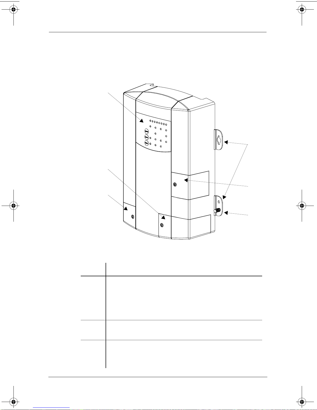
Truecharge™ 2 Battery Charger
This section describes the different parts of the Truechar ge™
2 Battery Charger.
1
3
2
5
Figure 1-1
Item Description
1 Onboard control and status display panel or simply
2 Mounting flanges are used to permanently install the
Truecharge™ 2 Battery Charger
onboard display (see “Rear Panel” on page 1–6 for
more information) for controlling the Truecharge™ 2
Battery Charger settings and for monitoring charger
status and charging current.
product.
4
6
3 DC wiring compartment cover protects the DC
1–4 975-0402-01-01
This guide for use by qualified installers only
terminals, as well as the communication and BTS ports.
Remove and replace when installing cables.
Page 19

Truecharge™ 2 Battery Charger
Item Description
4 Fuse access panel cover provides access to the DC fuse
in the event of an accidental reverse polarity installation.
5 AC wiring compartment cover provides the installer
with easy access to the AC wiring compartment, to
allow for a trouble free installation. Remove and replace
when installing the product.
6 DC ground stud for connecting the char ger’s chassis to
ground.
975-0402-01-01 1–5
This guide for use by qualified installers only
Page 20
Introduction
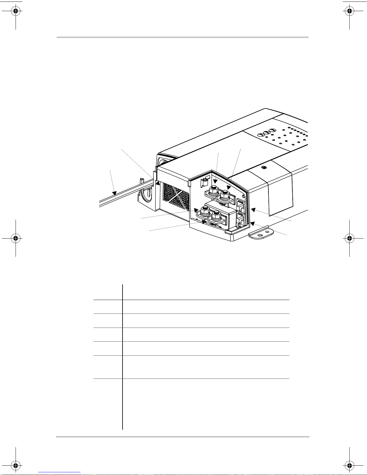
Rear Panel
This section describes the parts of the rear panel of the
Truecharge™ 2 Battery Charger.
7
8
5
6
40 A model (TC4012) shown. Other models may vary.
Figure 1-2
Item Description
1 BTS port- battery temperature sensor port
Truecharge™ 2 Battery Charger Rear Panel
4
3
2
1
2 Communication port - remote panel port
3 Battery positive (+) for bank 3 (6 mm stud)
4 Battery positive (+) for bank 2 (6 mm stud)
5 Battery positive (+) for bank 1 (6 mm stud)
6 Battery negative (–), common for all three banks
1–6 975-0402-01-01
This guide for use by qualified installers only
See Important note below.
(6 mm stud)
(common for both banks in model TC1512)
(model TC1012 has a single bank only–one positive
terminal and one negative terminal)
Page 21

Rear Panel
Item Description
7 Air intake vent - located inside is the fan assembly
8 AC wiring - line, neutral, and ground input wires
Important:
When installing only a single bank (or one
battery) for Truecharge™ 2 Battery Chargers that have
multiple outputs, positive bank 1 must be utilized. Bypassing
bank 1 and using any of the other banks (bank 2 or bank 3)
may render the charger to function improperly.
975-0402-01-01 1–7
This guide for use by qualified installers only
Page 22
Introduction
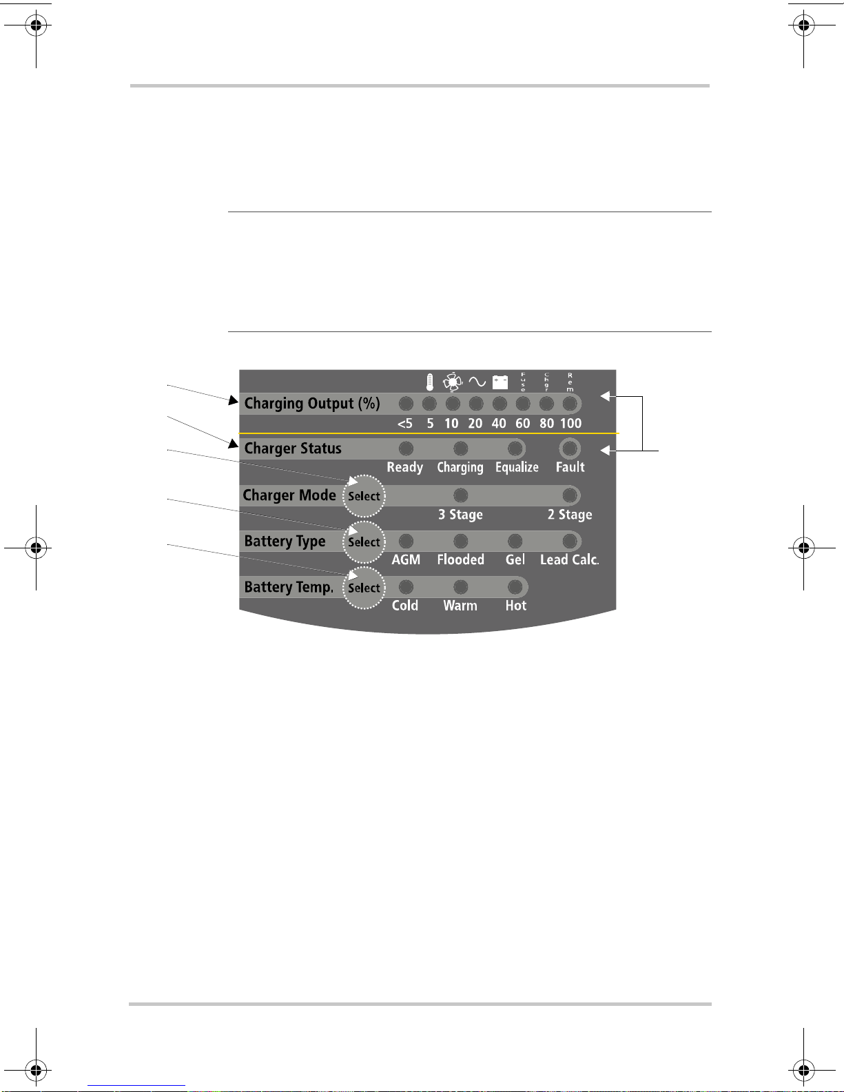
Onboard Control and Status Display Panel
This section describes the parts of the onboard control and
status display panel of the Truecharge™ 2 Battery Charger.
Important:
means that the button must be held down for more than three
seconds then released in order to send the instruction. A “press”
action on any panel button means that the button must be pressed
and released before two seconds have elapsed.
1
3
4
5
6
A “press and hold” action on any panel button
2
Figure 1-3
Onboard Control and Status Display Panel
To reduce current draw from the connected battery when AC
power is not present, the panel’s LED control and status
lights are automatically turned off and the buttons are
disabled.
1–8 975-0402-01-01
This guide for use by qualified installers only
Page 23

Onboard Control and Status Display Panel
Item Description
1 Charging Output (%) LEDs
• The LEDs illuminate like a progress bar displaying the present
total output charge current as a percentage of the set maximum
charge current. The numbers below the LEDs represent the
percentage values. See Figure 1-4 on page 1–11.
• A single LED may flash intermittently in combination with a solid
Fault LED (indicating a fault) or with a flashing Fault LED
(indicating a warning). The icons above the LEDs represent the
various types of fault and warning conditions. See Figure 1-4 on
page 1–1 1.
2 Fault LED
The LED may illuminate a solid light (indicating a fault) or fl ash
intermittently (indicating a warning) in combination with flashing
Charging Output (%) LEDs. See Table 1-1, “Fault and Warning
Indicators” on page 1–11 for details.
3 Charger Status LEDs
Displays the current status of the charger.
• Ready - a solid light indicates batteries are fully charged and in
rest stage.
• Ready and Charging - solid lights indicate batteries are fully
charged and in float stage.
• Charging - a solid light indicates charger is performing a normal
charge cycle.
• Equalize - a solid light indicates that the charger is performing an
equalization cycle.
- a flashing light indicates that the equalization cycle
will begin after the absorption stage is done.
4 Charger Mode Select button
• Press and hold the button for three seconds to select either of two
settings. An indicator LED corresponds to each setting. Each
setting optimizes the charging sequence differently in charging the
batteries by stages.
•Three-stage - Bulk, Absorption, and Float; default setting
•Two-stage - Bulk and Absorption only
• When setting or cancelling an Equalization program: Press and
hold both the Battery Temp. Select and Charger Mode Select
buttons.
975-0402-01-01 1–9
This guide for use by qualified installers only
Page 24

Introduction
Item Description
5 Battery Type Select button
Press and hold the button for three seconds to select either of five
settings. An indicator LED corresponds to each setting. Each setting
maximizes charger performance for its corresponding battery type.
•AGM - Absorbent Glass Mat lead-acid battery
• Flooded - Lead-acid battery; default setting
• GEL - Gel-type lead-acid battery
• Lead Calc. - Lead-calcium battery
• Custom - If a custom battery type has been programmed then all
LEDs will illuminate
6 Battery Temp. Select button
• Press and hold the button for three seconds to select one of three
settings. An indicator LED corresponds to each setting. Each
setting will change the charger’s internal threshold to compensate
for variance in battery voltage due to a change in temperature.
•Cold - for battery temperature below 5 °C (41 °F)
•Warm - for battery temperature between 5 and 30 °C
(41 and 86 °F); default setting
•Hot - for battery temperature above 30 °C (86 °F)
• When setting or cancelling an Equalization program: Press and
hold both the Battery Temp. Select and Charger Mode Select
buttons.
The Fault LED works in conjunction with the Charging
Current (%) LEDs. The icons at the top row above the
Charging Current (%) LEDs represent the various types of
fault and warning conditions. For example, a temperature
warning is represented by a thermometer icon.
The Charging Current (%) LEDs will normally illuminate as
a solid progress bar when they are indicating the amount of
output charging current. If any of the LEDs start to flash
intermittently at the same time that the Fault LED is either
solid or flashing, a fault or warning condition is indicated.
1–10 975-0402-01-01
This guide for use by qualified installers only
Page 25

Onboard Control and Status Display Panel
Important:
impending problem and will not stop the charger from
charging, while a fault condition will stop the charger from
charging the battery.
Charging Output (%)
Figure 1-4
Charging Output (%) and Fault LEDs
Table 1-1 on page 1–11 summarizes the various fault
conditions that might occur during the operation of the
charger. For suggestions in what to do after a fault condition
is detected, see Truecharge™ 2 Battery Charger Owner’s
Guide (doc. part number: 975-0401-01-01) on Table 3-1,
“Interpreting Fault and Warning Indicators” on page 3–4 in
Chapter 3, “Troubleshooting”.
A warning condition notifies the user of an
R
C
F
h
u
s
e
<5 5 10 20 40 60 80 100
g
r
e
m
Fault
Type of fault and warning
Charging Output (%) LEDs
Charging Output (%) values
Fault LED
Table 1-1
Fault and Warning Indicators
Fault or Warning
Condition
High Battery Temp
warning (>50°C)
See Figure 1-6.
High Battery Temp
fault (>70°C)
See Figure 1-6.
Low Battery Temp
warning (<0°C)
See Figure 1-6.
Flashing LED Solid LED
T emp Fan AC Battery Fuse Charger Remote Fault
F
u
s
e
C
h
g
r
R
e
m
975-0402-01-01 1–11
This guide for use by qualified installers only
Page 26

Introduction
Table 1-1
Fault and Warning Indicators
Fault or Warning
Condition
Low Battery Temp
fault (< -25°C)
See Figure 1-6.
AC input out of range
Warning (<104V and
>90V) or
(<264V and >255V)
See Figure 1-5.
AC input out of range
fault
(<90V or >265V)
See Figure 1-5.
AC frequency out of
range fault
(<45 Hz or >65 Hz)
T emp Fan AC Battery Fuse Charger Remote Fault
F
u
s
e
C
h
g
r
R
e
m
High Battery voltage
fault (>16.6V)
High Charger Temp
warning (>50°C)
High Charger Temp
fault (>70°C)
Locked Fan fault
Loss of Remote
Connection warning
Flashing LED Solid LED
1–12 975-0402-01-01
This guide for use by qualified installers only
Page 27

Onboard Control and Status Display Panel
Table 1-1
Fault and Warning Indicators
Fault or Warning
Condition
Reverse Polarity Fuse
fault
Internal fault
Flashing LED Solid LED
T emp Fan AC Battery Fuse Charger Remote Fault
F
u
s
e
C
h
g
r
R
e
m
Fault LED blinks if current is derated
in this region.
Imax
0.8 Imax
80 85 90 104 108 255 265 270 volts
Figure 1-5
Input
Voltage
Input Voltage Operating and De-rating Curve
975-0402-01-01 1–13
This guide for use by qualified installers only
Page 28

Introduction
-25 -20 -15 -10 -5 0 5 10 20 30 40 50 6015 25 35 45 55 65 70 °C
Figure 1-6
Charger
ALARM set
Charger
ALARM reset
Ambient Temperature
Charger
FAULT reset
derating to
80% Imax.
Battery and Charger Temperature Thresholds
Charger
FAULT set
1–14 975-0402-01-01
This guide for use by qualified installers only
Page 29

Remote Panel (Sold Separately)
Remote Panel (Sold Separately)
This section describes the parts of the optional remote panel
(Part number: 808-8040-00) of the Truecharge™ 2 Battery
Charger. The remote panel can be mounted using a
communications cable up to 15 m (50 ft) from the
Truecharge™ 2 Battery Charger connected via the
communication port for convenience.
Important:
means that the button must be held down for more than three
seconds then released in order to send the instruction. A “press”
action on any panel button means that the button must be pressed
and released before two seconds have elapsed.
2a
2
A “press and hold” action on any panel button
6a
4
6
8
1
Figure 1-7
Truecharge™ 2 Battery Charger Remote Panel (optional)
The Remote Panel can be used to:
• Program the charger for battery type and temperature
• Set the charger mode (two or three-stage charging)
• Activate and terminate equalization (not allowed for
GEL and AGM)
975-0402-01-01 1–15
This guide for use by qualified installers only
3
5
7
Page 30

Introduction
• Limit the maximum charger output current (20, 40, 60,
80, and 100% of charger rating) to lower the current
drawn from the generator or AC source
• Set the charger to
• Set or cancel an equalization cycle
• Display faults and warnings
• Display basic battery level and settings
Item Description
1
2 Charging Output (%) LEDs
ON/STANDBY Button
• Press to enable or disable the charger while AC power is
connected.
• When in Setup Mode: Press to select the Charger Mode: two or
three-stage.
• To set or cancel an Equalization program: Press and hold both the
Status and
• The LEDs illuminate a progress bar displaying the present total
output charge current as a percentage of the maximum charge
current. The numbers below the LEDs represent the percentage
values. See 2a on Figure 1-7 on page 1–15.
NOTE: The charger maximum current can be set using the Remote
Panel.
• An LED may flash intermittently in combination with a solid Fault
LED to indicate a fault or with a flashing Fault LED to indicate a
warning condition. The icons on the right side of the LEDs
represent different types of faults and warnings. See 6a on Figure
1-7 on page 1–15.
ON/STANDBY buttons.
ON or on STANDBY
1–16 975-0402-01-01
This guide for use by qualified installers only
Page 31

Item Description
3 Charger Status LEDs
Displays the present status of the charger.
• Ready - a solid light indicates that all batteries are fully charged
and in rest stage.
• Ready and Charging - solid lights indicate that batteries are fully
charged and in float stage.
• Charging - a solid light indicates that the charger is performing a
normal charge cycle.
• Equalize - a solid light indicates that the charger is performing an
equalization cycle.
- a flashing light indicates that the equalization cycle
will begin after the absorption stage is done.
4 Battery Status LEDs
Displays the present status of each battery (or each battery bank).
Each row represents the battery (or battery bank) num ber
designation—1, 2, or 3. Each column represents Low, Medium, or
Full battery capacity.
NOTE: This feature is available only on the Remote Panel.
Remote Panel (Sold Separately)
5 Status Button
• Press and hold to enter or exit Setup Mode.
• When in Setup Mode: Press to select the Battery Temperature:
C
old, Warm, or Hot.
• When setting or cancelling an Equalization program: Press and
hold both the Status and
6 Fault/Warning LED
The LED displays a solid light to indicate a fault condition or flashes
intermittently in combination with a flashing Charging Output (%)
LED to display a warning condition (6a). See Table 1-1, “Fault and
Warning Indicators” on page 1–11 for details.
7 Set Max Output Button
• P ress to select the desired maximum charging output current.
NOTE: This feature is available only on the Remote Panel.
• When in Setup Mode: Press to select the Battery Type: AGM,
Flooded, GEL, Lead-Calcium/OEM
8 Max. Output (%) LED
The LED illuminates a solid light corresponding to the Maximum
Charger Output % setting.
ON/STANDBY buttons.
975-0402-01-01 1–17
This guide for use by qualified installers only
Page 32

1–18
This guide for use by qualified installers only
Page 33

2
Chapter 2 provides procedures for installing, testing and
configuring the Truecharge™ 2 Battery Charger.
It covers the following major topics:
• “Preparing for Installation” on page 2–2.
• “Installing the Truecharge™ 2 Battery Charger” on
• “Installing Optional Accessories” on page 2–24
• “Configuring the Truecharge™ 2 Battery Charger”
• “Installing Batteries” on page 2–32
Installation
page 2–12
on page 2–26
This guide for use by qualified installers only
Page 34

Installation
Preparing for Installation
WARNING
The battery charger must be properly installed with in accordance
with all local and application-specific codes and ordinances before
it is used.
The Truecharge™ 2 Battery Charger is designed to be
permanently mounted. Figure 2-1 shows a typical installation
with three batteries, a battery temperature sensor (BTS) and a
remote panel (both optional). It also shows the AC and DC
wiring and protection devices required for a typical
installation. Means of disconnection must be incorporated
into the fixed wiring, in accordance with the electrical code
that governs each installation.
NOTE: Not to scale. For illustration purposes only.
L
N
G
1
2
4
5
6
8
10
3
7
6
9
Figure 2-1
2–2 975-0402-01-01
Typical Truecharge™ 2 Battery Charger System Installation
This guide for use by qualified installers only
6
Page 35

Preparing for Installation
1 AC mains source protected by correct size and type of branch rated
circuit breaker
2 AC input wiring compartment
3 DC negative cable
4 DC positive cables
5 DC circuit breakers or DC fused disconnects
6 Battery or battery bank
7 Engine ground bus or DC negative bus
8 Remote panel
(optional accessory part number: 808-8040-00)
9 Battery temperature sensor
(optional accessory part number: 808-0232-01)
10 DC chassis ground (earth)
975-0402-01-01 2–3
This guide for use by qualified installers only
Page 36

Installation
Tools and Materials
To mount and connect the Truecharge™ 2 Battery
Charger you need the following tools:
• 10 mm socket wrench and extension for the DC terminals
and ground stud
• Phillips screwdriver for removing and re-securing the AC
and DC wiring compartment covers
• power drill/screwdriver
• drill bit for pilot holes for mounting screws (if using #6
mounting screws, use 1/16 drill)
• wire stripper
• manufacturer's recommended crimp tool for any crimp
terminals that are being used
You need the following materials:
• 3 conductor AC input wiring
Use the information in “Planning AC W iring ” on page 2–
15 and your local electrical codes to determine the
correct wire and breaker or fuse.
• AC cable strain relief (if the one included is not
compliant with your local electrical code requirements)
• appropriately sized DC cables for each battery, with
suitable connectors at the battery end
• appropriately sized DC chassis ground (earth) with
suitable connectors
• ring terminals to fit 6 mm (1/4 in.) studs at the charger
end (Marine grade hardware is recommended).
• DC fused disconnect or properly rated circuit breaker for
each battery bank
• mounting screws, M3 or #6 marine grade, corrosion
resistant (4 pieces) (Length dependent on mounting
surface).
2–4 975-0402-01-01
This guide for use by qualified installers only
Page 37

Preparing for Installation
Location
Install the Truecharge™ 2 Battery Charger in a location that
meets the following requirements:
Condition Requirement
Dry The Truecharge™ 2 Battery Charger must be installed in a dry
location not subject to moisture especially rain, spray, or
splashing bilge water.
Clean The Truecharge™ 2 Battery Charger should not be exposed to
metal filings or any other form of contamination.
Cool The ambient air temperature should be between 0 °C - 50 °C
(32 °F - 122 °F) for best performance.
Ventilated There must be at least 10 cm (4 in.) of clearance on the top and
bottom ends of the Truecharge™ 2 Batter y Charger for air flow
and at least 6 cm (2.5 in.) of clearance on either side (see Figure
2-3). Ventilation openings on the charger must not be obst ruct e d.
If the charger is mounted in a tight fitting compartment, the
compartment must be ventilated with cut-outs to prevent the
charger overheating.
Safe This battery charger is ignition protected, so it can be installed in
areas containing gasoline tanks or fittings which require ignition
protected equipment. Xantrex recommends, however, that it is
safest not to install electrical equipment in these areas.
Close to
batteries
The Truecharge™ 2 Battery Charger should be installed as close
as possible to the batteries, but not in the same compartment to
prevent corrosion. Avoid excessive cable lengths and use the
recommended wire sizes. Xantrex recommends installing with
cables sized to achieve less than 3% voltage drop on battery
cables under full load. This will maximize the performance of the
charger.
When planning to install the Truechar ge™ 2 Battery Charger,
be sure that you consider the location and orientation
carefully. The Truecharge™ 2 Battery Charger is considered
to have an IP rating of IP-32, if installed in either of two
specific orientations [shown in Figure 2-2 a) and b)]. This
975-0402-01-01 2–5
This guide for use by qualified installers only
Page 38

Installation
rating means that it meets European and U.S. standards in
preventing dripping water from entering the enclosure, and
causing shock hazard and damage to equipment.
The other possible mounting orientations will not prevent the
entry of dripping water, and are not suitable for marine, or a
moist environment without the installation of additional drip
protection. They are only acceptable for use in locations that
are always dry [shown in Figure 2-2 c) and d)].
The environment, therefore, will determine the mounting
orientations that are suitable for each installation. Is the
installation environment one that will always be dry or will
moisture or condensation sometimes enter the area?
Important:
condensation will be present, and may drip on to the charger. Use
the appropriate mounting orientations as shown in Figure 2-2.
In marine environments, there is a likelihood that
For marine installations, the mounting orientations a) and b)
in Figure 2-2 meet the North American and European marine
requirements. Marine products are required to meet dripproof tests to ensure safety in the presence of condensation.
If you are certain your installation is not subject to moisture,
mounting orientations c) and d) in Figure 2-2 may be used.
2–6 975-0402-01-01
This guide for use by qualified installers only
Page 39

Preparing for Installation
a) b)
Deck Mount - this orientation meets IP-32
marine requirements and is drip-proof.
Horizontal Wall Mount (with AC wiring higher
than DC terminals only) - this orientation meets
c)
IP-32 marine requirements and is drip-proof.
d)
Vertical Wall Mount (Rear panel facing down or up) - this
orientation is allowed in locations that are always dry but
is not approved for marine installations without additional
drip protection.
AC
DC
Figure 2-2
6cm.
(2.5 in.)
Figure 2-3
Truecharge™ 2 Battery Charger Mounting Orientations
10 cm.
(4 in.)
Ventilation Clearance
975-0402-01-01 2–7
This guide for use by qualified installers only
Page 40

Installation
Wiring Requirements
WARNING: Shock and fire hazard
Wiring and fuse sizes are governed by electrical codes and
standards. Different requirements apply in different countries and to
different types of installations, for example, boat, home or RV. It is
the responsibility of the installer to ensure that each installation
complies with all applicable codes and standards.
WARNING: Shock and fire hazard
Ensure that both wires and fuses are correctly sized.
Maximum continuous current available from the charger may be an
additional 6–10% above the nominal current rating of the charger.
Output current may also vary depending on ambient temperature
conditions.
DC Wiring
The following two tables show some typical wire sizes, based
on 3% voltage drop on DC cables, 75 °C (167 °F) rated wire
and wiring being inside the engine compartment – assumed
ambient of 50 °C (122 °F).
Table 2-1
Wire Length
(max length one
way)
feet meters TC1012 TC1512 TC2012 TC3012 TC4012 TC5012 TC6012
51.5
7.5 2.25
20 6
DC Wiring Requirements for 12 V chargers
Wire Size (AWG and mm
No. 14
2mm
No. 12
3.3 mm
No. 8
8.4 mm
No. 12
2
3.3 mm
No. 10
2
5.3 mm
No. 6
2
13.3 mm
2
2
2
No. 10
5.3 mm
No. 10
5.3 mm
No. 6
13.3 mm
2
2
2
No. 10
5.3 mm
No. 8
8.4 mm
No. 4
21.2 mm
2
2
2
No. 8
8.4 mm
No. 6
13.3 mm
No. 2
33.6 mm
2
)
2
2
2
No. 6
13.3 mm
No. 6
13.3 mm
No. 2
33.6 mm
2
2
2
No. 6
13.3 mm
No. 4
21.2 mm
No. 1
42.4 mm
2
2
2
2–8 975-0402-01-01
This guide for use by qualified installers only
Page 41

Preparing for Installation
Table 2-2
Wire Length
(
max length one way)
DC Wiring Requirements for 24 V chargers
Wire Size (AWG and mm
2
)
feet meters TC1524 TC2024 TC3024 TC5024
51.5No. 16
1.3 mm
2
7.5 2.25 No. 14
2
2mm
20 6 No. 10
5.3 mm
2
No. 14
2mm
No. 12
3.3 mm
No. 8
8.4 mm
2
2
2
No. 12
3.3 mm
No. 10
5.3 mm
No. 6
13.3 mm
No. 10
2
5.3 mm
No. 8
2
8.4 mm
No. 4
2
21.2 mm
Over-current protection disconnect
Electrical codes require the DC circuit from each battery to
the charger to be equipped with a disconnect and an overcurrent protection device, usually within 7 inches (17.8 cm)
of each battery
1
. The devices are usually DC-rated circuit
breakers, fused disconnects, or a separate fuse and disconnect
for each circuit. These devices must be rated for DC voltage
and current and be rated to withstand the short circuit rating
of each battery. Do not substitute devices rated only for AC
voltage; they may not operate properly.
2
2
2
The current rating of the DC fuses must be correctly matched
to the size of the DC wiring used, in accordance with the
applicable codes. This helps to protect the installation against
fire in case of any overcurrent or short circuit fault.
The DC chassis ground (earth) should also be sized correctly
to provide ground fault protection (see Table 2-1). Refer to
the local electrical codes for your specific installation to
determine the correct gauge and length.
1.Recommended by the American Boating and Yachting Council.
975-0402-01-01 2–9
This guide for use by qualified installers only
Page 42

Installation
AC Wiring
WARNING: Risk of fire
Use only on circuits provided with 20A maximum branch circuit
protection in accordance with National Electrical Code, NFPA 70.
The AC wiring must meet be of sufficient size, and it must be
protected by the appropriate size and type of input breaker,
based on the jurisdiction and application. Some basic
examples are given below.
The AC input wiring for the Truecharge™ 2 Battery Charger
should be three-conductor cable, providing a line, neutral,
and ground conductor (or L, N,
a minimum of 75C.
For example, in North America for 120 Vac application, you
may use a 14 AWG wire with a 15 A breaker (or 12 AWG for
a 20 A breaker) or for 230 Vac application, you may be able
to use either a 2.5mm
or fuses or use 1.5 mm
2
wire with a 16 A, double pole breaker
2
wire with a 10 A, double pole breaker
or fuses. Note that every jurisdiction will have different
requirements as will each application, so research the
regulations for your local jurisdiction to determine which
wire size and type is correct. Another example:
• for marine applications, the United States American
Yachting and Boating Council (ABYC) requires stranded
wire, which is more robust than solid wire when exposed
to vibration
• for RV applications, the United States National Electrical
Code (NEC) allows solid wire in multi-conductor cable,
however, stranded wire is also acceptable which will
withstand vibration better.
The circuit supplying the Truecharge™ 2 Battery Charger
must be protected by the correct size and type of breaker to
meet the code for your local jurisdiction and application. If a
branch rated fuse is used, a correctly rated disconnect switch
is required ahead of the fuse so that power can be turned off,
allowing safe repair, or replacement of products on th e mains
circuit.
GND) in an outer jacket, rated
2–10 975-0402-01-01
This guide for use by qualified installers only
Page 43

Battery Bank Size Requirements
The Truech arge™ 2 Battery Char ger is designed to work with
a minimum battery bank size. Each bank should meet the
minimum Ah rating shown in Table 2-3.
Note: If the battery manufacturer has specified the maximum
charge current, please follow their recommendation.
Preparing for Installation
Table 2-3
12 V Models
TC1012
TC1512
TC2012
TC3012
TC4012
TC5012
TC6012
24 V Models
TC1524
TC2024
TC3024
TC5024
Minimum Battery Bank Size
Minimum Battery Bank Size (Ah)
30
30
80
80
80
100
100
Minimum Battery Bank Size (Ah)
30
50
60
100
975-0402-01-01 2–11
This guide for use by qualified installers only
Page 44

Installation
Installing the Truecharge™ 2 Battery
Charger
WARNING: Shock and Energy Hazards
Be sure to read the safety guidelines and pay attention to all
cautions and warnings throughout the installation procedure. The
installer is responsible for ensuring compliance with the installation
codes for your particular application.
Disconnect all sources of AC and DC power before proceeding.
Installation Sequence
To make charger installation quick and easy, Xantrex
recommends that the installation tasks be performed in the
following sequence:
1. Select charger mounting position and plan AC and DC
cable routing.
2. Plan DC cable runs and install fuses or breakers (page 2–
13).
3. Plan the AC connections at the charger (page 2–15).
4. Mount the charger in position (page 2–18).
5. Make the final DC (see page 2–19) and then AC cable
connections (including earth grounds) (page 2–19).
6. Apply DC to the charge by closing the DC breakers or
disconnects (page 2–23).
7. Apply mains AC to the charger by closing the AC input
breaker.
2–12 975-0402-01-01
This guide for use by qualified installers only
Page 45

Planning DC Wiring
The procedure for installing the DC wiring applies to a single
battery, as well as multiple batteries or battery banks.
WARNING: Fire or burn hazard
To help prevent accidental shorts or sparks, leave the DC
disconnects or breakers in the Off position or DC fuses removed
from their fuse holders until installation is complete.
WARNING: Fire or burn hazard
The rubber boots must be installed over the Truecharge™ 2 Battery
Charger DC terminals to provide drip protection, and protect
against short circuits between output terminals. See “To install
rubber boots:” on page 2–20.
Installing the Truecharge™ 2 Battery Charger
1. Identify the battery or bank that most frequently becomes
deeply discharged. This bank will often be a deep cycle
battery referred to as the House Bank on a boat, as
opposed to an engine Start Battery. This high priority
bank should be connected to bank 1 on the Truecharge™
2 Battery Charger, which is the default bank.
2. Plan the route that the DC wires will follow , keeping it as
short as possible. Measure and cut the required wire
length, after allowing some extra length for connections
and to provide slack in the wires for strain relief.
3. Identify the positive wires, by using color-coded wire, or
by marking both ends of the wire with colored tape, or
similar kind of marking. Repeat with a different color for
the negative. Most installation codes recommend
coloring the positive red and the negative black.
Important:
associating it with the battery bank it is connected to. For
example, bank 1 (–), bank 1 (+), bank 2 (–).
You may find it helpful to label each cable,
975-0402-01-01 2–13
This guide for use by qualified installers only
Page 46

Installation
4. Install a DC circuit breaker or fused disconnect in each
positive cable within 7 inches (17.8 cm) of each battery.
Consult your local electrical codes regarding the distance
between the battery and the disconnect device. Be sure
the breaker or fused disconnect is open.
5. Route the wiring to the batteries and to the Truecharge™
2 Battery Charger. Avoid routing wiring through an
electrical distribution panel, battery isolator, or other
device that will add voltage drops.
6. Install crimp lugs on each end of the DC battery cables
using the crimp manufacturer’s instructions and tool.
7. Install the provided rubber boots over the charger end of
the DC cables. Install rubber boots over the Truecharge™
2 Battery Charger DC terminals to provide drip and
added corrosion protection. Follow the procedure on
page 2–24 to install rubber boots.
8. Route the optional battery temperature sensor (BTS)
from the battery (one which is located in the warmest
ambient temperature) to the charger location.
9. Proceed to “Planning AC Wiring”.
2–14 975-0402-01-01
This guide for use by qualified installers only
Page 47

Planning AC Wi ring
Before connecting AC wiring, make sure the AC source
circuit is protected by a breaker switch of the correct size and
type, to comply with the electrical code for your location and
application. The current rating of the input breaker should not
be larger than 20A.
1. Disconnect the AC source by turning off the breaker
feeding the circuit, unplugging from shorepower and
disconnecting any other power sources (such as a
generator).
2. Plan the route that the AC wiring will follow from the
source (usually an AC distribution panel) to the
Truecharge™ 2 Battery Charger. Measure and cut the
required length of three-conductor cable allowing some
extra length for connections and providing some slack.
For example, in North America for 120 Vac application,
you may use a 14 AWG wire with a 15 A breaker (or
12 AWG for a 20 A breaker) or for 230 Vac application,
you may be able to use either a 2.5mm
double pole breaker or fuses or use 1.5 mm
10 A, double pole breaker or fuses. Note that every
jurisdiction will have different requirements as will each
application, so research the regulations for your local
jurisdiction to determine which wire size and type is
correct.
Installing the Truecharge™ 2 Battery Charger
2
wire with a 16 A,
2
wire with a
3. Make the AC connections to the charger when it is sitting
on a table or other convenient work surface.
Route the AC cables to the source after the charger is
securely mounted in position, using all four mounting
holes.
4. Unscrew the wiring compartment cover from the left rear
of the Truecharge™ 2 Battery Charger to expose the AC
wiring access hole.
5. Carefully remove 50 – 75 mm (2 – 3 in.) of the outer
jacket from the source panel wiring, being careful not to
cut or nick the insulation on the individual conductors.
975-0402-01-01 2–15
This guide for use by qualified installers only
Page 48

Installation
6. Remove the AC (L, N, GND) wires from the AC wiring
compartment of the charger.
7. Feed the source AC wire through the included strain
relief. Position approximately 1" from end of jacketed
portion of the AC wiring.
8. Connect the AC wiring to the Truecharge™ 2 Battery
Charger pigtail wires, being sure to connect the line
conductor to the line, the neutral to the neutral, and the
ground to the ground. The pigtail wires are color coded
as follows:
Conductor Color code
Line Black or brown
Neutral White or blue
Ground Green with yellow stripe
Make the connections using crimp-on connectors or with
other approved connectors required by your code, and
suitable for your installation. For example, the ABYC
Standards and Recommended Practices for Small Craft
prohibit twist-on connectors for AC connections on a
boat. For other types of installation, refer to your
applicable code.
For marine installations, follow the connector
manufacturer’s procedure for installing butt splice
connectors.
2–16 975-0402-01-01
This guide for use by qualified installers only
Page 49

Installing the Truecharge™ 2 Battery Charger
To connect AC wires with the crimp-on butt-splice connector:
Important:
connectors. Use the crimp tool recommended by the manufacturer
for the connector used.
You must exercise care when crimpi ng but t-splice
a) Using a wire stripper, carefully strip 8 mm (5/16 in.)
from the ends of the two wires being connected.
b) Insert one wire into one end of the butt-splice, until
the insulation hits the internal metal crimp section,
insert the butt-splice into the crimping tool, and
crimp firmly. The proper location for the crimp is
approximately 1.6 mm (1/16 in.) past where the buttsplice insulation tapers down as shown.
STRIP 5/16”
CRIMP TOOL
c) Repeat Step b for the other end of the butt-splice.
9. Slide the strain relief into the bottom half of the strain
relief retention hole in the charger.
10. When all connections are completed, push the wiring and
connectors inside the AC wiring compartment. Install the
wiring compartment cover and tighten the screw on top
to secure the cover. Do not over-tighten.
11. Proceed to “Mounting the Optional Remote Panel” on
page 2–24, if you have the optional remote panel
otherwise, proceed to “Mounting the Truecharge™ 2
Battery Charger” on page 2–18.
975-0402-01-01 2–17
This guide for use by qualified installers only
Page 50

Installation
Mounting the Truecharge™ 2 Battery Charger
Mount the Truecharge™ 2 Battery Charger using all four
mounting slots and holes which are provided. For marine
only installations, the mounting orientations a) and b) in
Figure 2-2 meet the North American and European marine
requirements. Marine products are required to meet dripproof tests to ensure safety in the presence of condensation.
The other possible mounting orientations c) and d) also
shown in Figure 2-2 will not prevent the entry of dripping
water, and are not suitable for marin e, or a moist environment
without the installation of additional drip protection. They are
only acceptable for use in locations that are always dry.
Important:
plan the routing of the cables before drilling the pilot holes for
mounting the Truecharge™ 2 Battery Charger.
Be sure to measure your AC and DC cables and
To mount the Truecharge™ 2 Battery Charger:
1. Keep the carton and packing material in case you need to
return the Truecharge™ 2 Battery Charger for servicing.
2. Ensure that you have selected a mounting surface that is
clear, flat and allows for a minimum of 10 cm (4 in.) of
clearance on the top and bottom ends for air flow and at
least 6 cm (2.5 in.) of clearance on either sides (see
Figure 2-3, “Ventilation Clearance” on page 2–7)
3. Drill the four pilot holes for the mounting screws, taking
care that there is nothing behind the surface that can be
damaged by the drill.
4. Mount the Truecharge™ 2 Battery Charger using
corrosion resistant, #6 (3 mm) round, pan head (or
similar) screws.
The top two keyhole-style mount ing holes can be used to
hold the Truecharge™ 2 Battery Charger in place while
fastening the bottom two screws. For secure, permanent
mounting, use the holes in all four mounting flanges and
fasten all four screws. The keyhole slots should not be
used solely for the installation of the charger.
2–18 975-0402-01-01
This guide for use by qualified installers only
Page 51

Installing the Truecharge™ 2 Battery Charger
Make the Final Connections
After planning the DC and AC connections and mounting the
charger, the last procedures, including installing the DC
terminal rubber boots for drip protection, will finalize the
wiring connections.
NOTE: Not to scale. For illustration purposes only.
L
N
G
2
1
3
4
15
DC connections
1. Negative Cable (main) to charger.
2. Positive Cable (bank 1*) to charger.
3. Positive Cable (bank 2) to charger.
4. Positive Cable (bank 3) to charger.
5. Positive Cable (bank 1*) to battery.
6. Positive Cable (bank 2) to battery.
7. Positive Cable (bank 3) to battery.
8. Negative Cable (A) to battery terminal (bank 1*).
9. Negative Cable (A) to DC negative bus (bank 1*).
10. Negative Cable (B) to battery terminal (bank 2).
11. Negative Cable (B) to DC negative bus (bank 2).
12. Negative Cable (C) to battery terminal (bank 3).
13. Negative Cable (C) to DC negative bus (bank 3).
14. Negative Cabl e (main) to negative bus bar.
15. Gro und Cable to DC ground stud.
6
7
5
8
14
12
10
* see Important note below.
13
11
9
Important:
Truecharge™ 2 Battery Chargers that have multiple outputs, positive bank
1 must be utilized. Bypassing bank 1 and using any of the other banks
(bank 2 or bank 3) may render the charger to function improperly.
Figure 2-4
Final DC Wiring Connection Order
975-0402-01-01 2–19
This guide for use by qualified installers only
When installing only a single bank (or one battery) for
Page 52

Installation
Installing the Drip Protection Rubber Boots
Xantrex recommends that you install the supplied rubber
boots over the Truecharge™ 2 Battery Charger DC terminals
to provide drip and short circuit protection.
To install rubber boots:
1. Before making the DC connections to the charger, feed
the rubber boot over the charger end of the DC cables.
2. Perform all other DC connections as described in
“Planning DC Wiring” on page 2–13.
3. After the DC cables are connected to the charger, slide
the boot up the cables and over the DC terminals. If you
are only using one battery, slide the spare boots over the
unused DC terminals.
The Truecharge™ 2 Battery Charger is provided with drip
protection rubber boots for the DC terminals.
Final DC Connections
WARNING: Fire and burn hazard
Make sure that the DC fuse and circuit breaker are open.
To make the final DC connections (see Figure 2-4 on page
2–19):
1. Connect the negative cable fro m the negative terminal on
the battery (if you are using only one battery or bank), or
the negative ground bar or bus (if you are using more
than one battery or bank), to the negative DC terminal on
2–20 975-0402-01-01
This guide for use by qualified installers only
Page 53

Installing the Truecharge™ 2 Battery Charger
the Truecharge™ 2 Battery Charger (Figure 2-4, item 1).
Use a flat washer, a lock washer and a nut (5 included in
the installation kit) to secure the connection.
Tighten the nuts to 2.3 N-m (20 lb-in.) torque and test
that the wire is secure. Do not over-tighten as this may
result in damage to the charger.
2. Connect each positive cable to the correct positive DC
terminal on the Truecharge™ 2 Battery Charger (Figure
2-4, items 2 to 4). Use a flat washer, a lock washer and a
nut (5 included in the installation kit) to secure the
connection.
Tighten the nuts to 2.3 N-m (20 lb-in.) torque and test
that the wire is secure.
3. Connect the free end of each positive cable to the correct
positive terminal of the battery (Figure 2-4, items 5 to 7),
using sufficient torque as recommended by your battery
manufacturer.
4. Connect the free end of the negative cable to the negative
terminal on the battery (Figure 2-4, items 8, 10, and 12),
using sufficient torque as recommended by your battery
manufacturer.
NOTE: If you are using more than one battery, you will
need to connect the negative cable from each of the
batteries to the negative ground bar or bus (Figure 2-4,
items 9, 11, and 13). The negative ground bar or bus will
then have a single negative cable connecting to the
negative charger terminal (Figure 2-4, item 14).
CAUTION: Reverse polarity damage
Before proceeding, carefully check the wiring polarity – make sure
the positive terminals of the Truecharge™ 2 Battery Charger are
connected to the correct terminals of the battery (fuses or breakers)
and from there to the positive terminals of the battery. Make sure
the negative terminal of the Truecharge™ 2 Battery Charger is
connected to the battery negative terminal (or DC negative bus). Do
not reverse the connections.
975-0402-01-01 2–21
This guide for use by qualified installers only
Page 54

Installation
5. Install the DC chassis ground (earth) from the ground
stud on the Truecharge™ 2 Battery Char ger to the engine
bus or DC ground bus (Figure 2-4, item 15). Use a flat
washer, a lock washer and a nut (included in the
installation kit) to secure the connection.
Tighten the nuts to 2.3 N-m (20 lb-in.) torque and test
that the wire is secure. Do not over-tighten as this may
result in damage to the charger.
6. Connect any optional accessories. See “Installing
Optional Accessories” on page 2–24.
7. Secure cables in place using tie-wraps, P-clamps or cable
straps according to electrical codes. Coil and tie any BTS
or remote panel extension cable.
8. The DC breakers may be closed at this time.
Final AC Connections
To make the final AC connections:
1. Complete the installation by routing the AC cable to the
AC source.
2. Connect the AC cable to the AC disconnect breake r and
ground in accordance with the color codes on page 2–16.
3. Secure cables in place using tie-wraps, P-clamps or cable
straps according to electrical codes.
4. The AC mains may be applied at this time by closing the
breaker.
2–22 975-0402-01-01
This guide for use by qualified installers only
Page 55

Grounding Instructions
WARNING: Electric shock hazard
Have an electrician install a properly grounded circuit if one is not
available. Improper connection can result in risk of an electric
shock.
The Truecharge™ 2 Battery Charger Battery Charger must be
connected to a grounded, metal permanent wiring system, or
an equipment-grounding conductor should be run with the
circuit conductors and connected to equipment-grounding
lead on the charger . Connections to the battery charger should
comply with all local and application-specific codes and
ordinances.
Xantrex recommends that you install a DC chassis ground
(earth) from the ground stud on the Truecharge™ 2 Battery
Charger to the engine bus or DC ground bus. The DC chassis
ground (earth) should be sized correctly with the power
conductors, and both must be sized for the battery fuses that
are used to protect the DC wiring. Refer to your local
electrical codes to verify the requirements in your jurisdiction
for your application.
Installing the Truecharge™ 2 Battery Charger
Powering Up
Make one last check that all connections and connectors are
secure.
The Truecharge™ 2 Battery Charger charger may now be
powered up. Switch the AC power on at the source breaker . It
is normal to see a 7-10 second delay while the charger powers
up. During this time, the indicator LEDs on the onboard
display and the remote panel will illuminate for a second
(power on test) before reporting charging and battery status
information.
Note: The indicator LEDs will also illuminate when DC power
is applied and battery bank 1 voltage is above 9V.
975-0402-01-01 2–23
This guide for use by qualified installers only
Page 56

Installation
Installing Optional Accessories
Optional accessories are available for purchase at Xantrex.
Call Customer Service to order the accessories below:
• Remote Panel (Part number: 808-8040-00)
• Battery Temperature Sensor (Part number: 808-0232-01)
Mounting the Optional Remote Panel
To mount the remote panel:
1. Choose a location for the remote panel that is within
15 m (50 ft.) from the charger. Use only the fourconductor communications cable (RJ-11) that came with
the remote panel.
2. Use the enclosed mounting template to predrill mounting
holes.
Take care that there is nothing behind the surface for you
to damage such as other cables or pipes.
3. Connect the RJ-11 connector to the remote panel and
route it to the charger. Be careful not to damage the
connector locking tab when routing the cable. You can
use some tape to protect the locking tab from catching on
something and breaking off when routing the cable.
4. Once the Truecharge™ 2 Battery Charger is mounted,
plug the other RJ-11 connector into the Remote port on
the rear panel of the Truecharge™ 2 Battery Charger.
2–24 975-0402-01-01
This guide for use by qualified installers only
Page 57

Installing Optional Accessories
Installing the Optional Battery Temperature Sensor
(BTS)
Xantrex strongly recommends that you install the optional
Battery Temperature Sensor (BTS) to protect your battery
and improve charging accuracy. If no BTS is connected, the
charger defaults to the charging temperature settings (Cold,
Warm, or Hot). It is important to set this before the BTS is
installed to ensure that even when the BTS connection is
subsequently lost due to a BTS malfunction or a severed or
loose wire connection, an approximate representation of the
battery temperature is passed on to the charger.
To install a BTS:
1. Switch off all devices operating from the battery.
2. Connect the ring terminal on the sensor directly on to the
negative battery stud, or affix the double-sided adhesive
backing to the sensor back and attach the sensor to the
side of the battery to be monitored.
NOTE: If there are multiple batteries, attach the BTS to
the battery that is located in the warmest ambient
temperature.
3. Route the sensor cable to the charger and plug it to the
BTS port on the rear panel.
Important:
BTS cables should be routed away from the AC mains line and
DC battery cables.
Also, if the BTS is unplugged after a battery overtem perature
fault, the charger will stop charging. Use the onboard display to
set the appropriate temperature setting to restart charging.
To minimize noise interference, the remote and
CAUTION: Battery damage
In the absence of a BTS, setting a battery temperature that is lower
than the actual temperature will cause the battery to be overcharged
and may damage or reduce the life of the battery or cause a hazard.
Setting the temperature higher than the actual temperature will
result in under-charging the battery.
975-0402-01-01 2–25
This guide for use by qualified installers only
Page 58

Installation
Configuring the Truecharge™ 2 Battery
Charger
Once the charger is connected to a battery on bank 1 or to
AC, it is live and it may be configured. The indicator LEDs
on the onboard display will illuminate for a second (power on
test) before reporting charging and battery status information.
When the remote panel is connected, there will be a short
delay of about 1three seconds before reporting charging and
battery status information. The remote panel will use this
time to query the charger for the current operating conditions.
If AC was already applied, ensure that the charger is ON by
pressing
ON/STANDBY if necessary.
2–26 975-0402-01-01
This guide for use by qualified installers only
Page 59

Configuring the Truecharge™ 2 Battery Charger
Configuring the Charger Mode
Using the Onboard Display Panel
To configure the charger mode:
Note: By default, the Cha rger Mode is set to three-stage.
1. Press and hold the Charger Mode Select button for three
seconds.
2. Select the proper charger mode.
The LEDs will indicate which of the two modes is being
selected: three-stage (default) or two-stage.
Figure 2-5
975-0402-01-01 2–27
Onboard Display Panel
This guide for use by qualified installers only
Page 60

Installation
Using the Remote Panel
To configure the charger mode:
Note: By default, the Cha rger Mode is set to three-stage.
1. Press and hold the Status button for three seconds to enter
the Setup mode.
Entering the Setup mode will enable you to select the
charger mode.
2. Press
3. Press and hold the Status button for three seconds to exit
Charger Mode
ON/STANDBY button to select the desired charger
mode.
The LEDs will indicate which of the two types is being
selected: three-stage (default) or two-stage.
the Setup mode.
Maximum Output Current (%)
ON/STANDBY button
Figure 2-6
2–28 975-0402-01-01
Remote Panel
This guide for use by qualified installers only
Battery Temperature
Battery Type
Page 61

Configuring the Truecharge™ 2 Battery Charger
Configuring the Battery Bank Type
Using the Onboard Display Panel
To configure the battery bank type:
Note: By default, the battery type is set to Flooded.
1. Press and hold the Battery Type Select button for three
seconds.
2. Select the proper battery type.
The LEDs will indicate which of the four types is being
selected: Flooded (default), GEL, Lead Calc., AGM.
However, if a custom battery type has been programmed
by the OEM, all four LEDs will light up to indicate a fifth
type.
Using the Remote Panel
To configure the battery bank type:
Note: By default, the battery type is set to Flooded.
1. Press and hold the Status button for three seconds to enter
the Setup mode.
Entering the Setup mode will enable you to select the
battery type.
2. Press Set Max Output button to select the proper battery
type.
The LEDs will indicate which of the four types is being
selected: Flooded (default), GEL, Lead Calc., or AGM.
However, if a custom battery type has been programmed
by the OEM, all four LEDs will light up to indicate a fifth
type.
3. Press and hold the Status button for three seconds to exit
the Setup mode.
975-0402-01-01 2–29
This guide for use by qualified installers only
Page 62

Installation
Configuring the Battery Temperature without the
BTS
Using the Onboard Display Panel
To configure the battery temperature:
Note: By default, the Battery Temp. is set to Warm.
1. Press and hold the Battery Temperature Select button for
three seconds.
2. Select the appropriate battery temperature setting.
The LEDs will indicate which of the three types is being
selected: Warm, Hot, or Cold.
Note: Cold is for battery temperature below 5 °C (41 °F). Warm
is for battery temperature between 5 and 30 °C (41 and 86 °F);
default setting. Hot is for battery temperature above 30 °C (86 °F).
See “Battery T emperature Compensation Levels” on page 2–31 to
see how output voltage is offset by varying the temperature
selection.
Using the Remote Panel
To configure the battery temperature:
Note: By default, the Battery Temp. is set to Warm.
1. Press and hold the Status button for three seconds to enter
the Setup mode.
Entering the Setup mode will enable you to select the
battery temperature setting.
2. Press Status button to select the appropriate battery
temperature setting.
The LEDs will indicate which of the three types is being
selected: W(arm), H(ot), or C(old).
3. Press and hold the Status button for three seconds to exit
the Setup mode.
2–30 975-0402-01-01
This guide for use by qualified installers only
Page 63

Configuring the Truecharge™ 2 Battery Charger
Table 2-4
Temperature
Selection
Cold below 5 °C
Warm between
Hot above 30 °C
Battery Temperature Compensation Levels
Recommended
for battery
temperature of:
(41 °F)
5 and 30 °C
(41 and 86 °F)
(86 °F)
Voltage added for temperature
compensation offset from 25 °C
Flooded/PbCa/Gel 0.675
AGM 0.525
Flooded/PbCa/Gel 0
AGM 0
Flooded/PbCa/Gel -0.27
AGM -0.21
Configuring the Maximum Output Current
Percentage
Using only the Remote Panel
To configure the maximum output curr e nt:
Note: By default, the Max. Output % is set to 100.
Press the Set Max Output button to select the appropriate
maximum output setting.
The LEDs will indicate which of the five values is being
selected: 100, 80, 60, 40, or 20.
975-0402-01-01 2–31
This guide for use by qualified installers only
Page 64

Installation
Installing Batteries
Replacing old or defective batteries (even installing new
batteries) require that you disconnect all AC and DC sources
prior to installation.
WARNING
Battery installation should always be treated like a brand new
installation. This means, that all safety and precautionary
guidelines that were followed prior and during the installation of
the charger, must again be followed in order to avoid risks of
electrical shock, injury, or death.
To replace an old battery:
1. Turn off the AC source by disconnecting the AC line.
2. Switch off all devices operating from currently installed
batteries.
3. Disconnect the battery cables from the old battery.
NOTE: Disconnect the negative cable first, then the
positive cable. Inspect all AC and DC cables for damage
and repair, if necessary.
4. Replace the old battery with the new battery.
5. Reconnect the battery cables to the new battery.
NOTE: Reconnect the positive cable first, then the
negative cable.
Important:
chemistry, temperature, or size, remember to re-configure the
battery settings accordingly.
If the new battery is different from the old one in
2–32 975-0402-01-01
This guide for use by qualified installers only
Page 65

A
Appendix A contains physical, electrical performance,
and regulatory approval specifications for the
Truecharge™ 2 Battery Charger.
Note: Specifications are subject to change without notice.
Specifications
This guide for use by qualified installers only
Page 66

Specifications
Physical Specifications
Base Unit
Dimensions:
L × W × H
Weight TC1012, TC1512: 2.0 kg (4.4 lbs)
AC input
connections
TC1012, TC1512:
200 × 170 × 70mm (7.87 × 6.70 × 2.76 in.)
TC2012, TC3012, TC4012:
250 × 170 × 70mm (9.84 × 6.70 × 2.76 in.)
TC5012, TC6012:
350 × 170 × 70mm (13.78 × 6.70 × 2.76 in.)
TC1524, TC2024:
250 × 170 × 70mm (9.84 × 6.70 × 2.76 in.)
TC3024, TC5024:
300 × 210 × 125mm (11.81 × 8.27 × 4.92 in.)
TC2012, TC3012, TC4012: 2.2 kg (4.8 lbs)
TC5012, TC6012: 4.5 kg (9.9 lbs)
TC1524, TC2024: 2.2 kg (4.8 lbs)
TC3024, TC5024: 5.0 kg (11.0 lbs)
Two color-coded No. 14 AWG wires (L, N) and one
No. 14 AWG (G) minimum 152 mm (6 in.) long in a separate
AC wiring enclosure with 21.3 mm (0.84 in.) hole provision for
connection of a ½ inch North American "trade size" cable clamp
(included).
DC output
connections
TC1012:
Two M6 studs (1 positive and 1 common negative) for battery
cable ring terminals and one M6 mm DC equipment ground
TC1512:
Three M6 studs (2 positives and 1 common negative) for battery
cable ring terminals and one M6 mm DC equipment ground
TC2012, TC3012, TC4012, TC5012, TC6012, TC1524,
TC2024, TC3024, TC5024:
Four M6 studs (3 positives and 1 common negative) for battery
cable ring terminals and one M6 mm DC equipment ground
A–2 975-0402-01-01
This guide for use by qualified installers only
Page 67

Electrical Specifications
Electrical Specifications
Number of isolated
battery bank outputs
Nominal battery voltage 12 V units:12 Vdc
Normal operating output
range
Nominal operating AC
input voltage
Maximum DC output
current (total)
TC1012:
1 output
TC1512:
2 separated outputs
TC2012, TC3012, TC4012, TC5012, TC6012,
TC1524, TC2024, TC3024, TC5024:
3 separated outputs
24 V units:24 Vdc
12 V units: 0 – 16 Vdc
24 V units: 0 – 32 Vdc
110 – 250 Vac
TC1012: 10 ±10% A
TC1512: 15 ±10% A
TC2012: 20 ±10% A
TC3012: 30 ±10% A
TC4012: 40 ±10% A
TC5012: 50 ±10% A
TC6012: 60 ±10% A
TC1524: 15 ±10% A
TC2024: 20 ±10% A
TC3024: 30 ±10% A
TC5024: 50 ±10% A
Absorption voltage:
±0.1 V for 12 V units
±0.2 V for 24 V units
975-0402-01-01 A–3
This guide for use by qualified installers only
12 V units 24 V units
25°C (77°F) 25°C (77°F)
Flooded 14.4 28.8
GEL 14.2 28.4
AGM 14.3 28.6
Lead-calcium 15.5 31.0
Page 68

Specifications
Float voltage:
±0.1 V for 12 V units
±0.2 V for 24 V units
Flooded 13.5 27.0
12 V units 24 V units
25°C (77°F) 25°C (77°F)
GEL 13.8 27.6
AGM 13.4 26.8
Lead-calcium 13.5 27.0
Equalize mode current 50% rated output ±6%
Equalize mode—
maximum output
12 V units:16 ±0.1 Vdc
24 V units:32 ±0.2 Vdc
voltage
Off-state current draw
(without remote
12 V units: <30 mA
24 V units: <20 mA
installed)
A–4 975-0402-01-01
This guide for use by qualified installers only
Page 69

AC Input Specifications
AC Input Specifications
AC input voltage range Nominal: 120 Vac, 230 Vac, 240 Vac
Full Performance: 105 – 265 Vac ±4 Vac
Automatic derating to 80%: 90 – 104
±4 Vac
Maximum AC input current at 104 Vac at 208 Vac
TC1012: 2.5 A TC1012: 1.5 A
TC1512: 3.5 A TC1512: 2.0 A
TC2012: 4.5 A TC2012: 2.5 A
TC3012: 7.0 A TC3012: 3.5 A
TC4012: 9.0 A TC4012: 4.5 A
TC5012: 11.5 A TC5012: 5.5 A
TC6012: 13.5 A TC6012: 6.5 A
TC1524: 7.0 A TC1524: 3.5 A
TC2024: 9.0 A TC2024: 4.5 A
TC3024: 13.5 A TC3024: 7.0 A
TC5024: 22.5 A TC5024: 11.5 A
Power factor at rated load ≥0.95
Frequency 47 – 63 Hz
Efficiency – peak 12 V units: 77% @ 120 Vac, 80% @
230 Vac
24 V units: 85% @ 120 Vac, 87% @
230 Vac
Surge protection Line-to-neutral surge protector rated at 275
Vac
975-0402-01-01 A–5
This guide for use by qualified installers only
Page 70

Specifications
DC Output Specifications
DC output voltage range including
dead battery charging voltage
Maximum equalization voltage
(no BTS installed)
Voltage accuracy (no load) 12 V units: ±0.1 Vdc at 14.4 Vdc @ 25 °C
Voltage regulation Uncompensated load voltage regulation <
12 V units: 0 – 15.5 Vdc
24 V units: 0 – 31 Vdc
12 V units: 16 Vdc
24 V units: 32 Vdc
(77 °F)
24 V units: ±0.2 Vdc at 28.8 Vdc @ 25 °C
(77 °F)
0.1Vdc drop from 0 Amps to rated current
output at charger output terminals (adds in
series with recommended 3% limit for
user's battery cable voltage drop).
Temperature Specifications
Nominal ambient 25 °C (77 °F)
Operating range
Current de-rating (above 50 °C
ambient temperature)
Storage –40 to 80 °C (–40 to 176 °F)
Humidity 5 – 95%, RH non-condensing
(full performance) –20 – 50 °C (–4 – 122 °F)
upto 80% derating Imax
(50 – 65 °C) (122 – 149 °F)
A–6 975-0402-01-01
This guide for use by qualified installers only
Page 71

Protection Features
Protection Features
Battery reverse
polarity
Over-voltage limits The Truecharge™ 2 Battery Charger will stop
Output current limit TC1012 : 10 ±10% A (up to 15.5 V)
Over-temperature Internal charger temperature is measured. Charger
Protected by a replaceable DC output fuse
charging any bank if the output voltage is above
16.6 ±0.5 Vdc.
TC1512: 15 ±10% A (up to 15.5 V)
TC2012: 20 ±10% A (up to 15.5 V)
TC3012: 30 ±10% A (up to 15.5 V)
TC4012: 40 ±10% A (up to 15.5 V)
TC5012: 50 ±10% A (up to 15.5 V)
TC6012: 60 ±10% A (up to 15.5 V)
TC1524: 15 ±10% A (up to 31 V)
TC2024: 20 ±10% A (up to 31 V)
TC3024: 30 ±10% A (up to 31 V)
TC5024: 50 ±10% A (up to 31 V)
shuts down and restarts as follows:
• Shutdown at 70 °C (158 °F)
• Restart at 65 °C (149 °F)
Current derating in
ambient
temperatures
Battery overtemperature
protection
975-0402-01-01 A–7
Rated current to 50 °C (122 °F)
derating to 80% Imax above 50 °C (122 °F)
Battery temperature, as sensed by the battery
temperature sensor (if installed), results in the
charger no longer charging the individual battery or
bank at a battery temperature of 70 °C (158 °F).
This guide for use by qualified installers only
Page 72

Specifications
Approvals
Safety NR TL approved to CSA E60335-2-29 and UL1236, including the
marine supplement, ignition protection, and UL1564
CE marked, complying with Low Voltage Directive 2006-95-EC,
complying with EN60335-2-29 Battery Chargers, including
Australian deviations
ISO 8846: Ignition Protection for Small Craft
ABYC E11 - Alternating Current and Direct Current Electrical
Systems on Boats
ABYC A31 - Battery Chargers and Inverters
NFPA 70/2008 US NEC for home and RV installation
requirements
EMC FCC Class B
CE marked, meeting EMC Directive 2004-108-EC
Other KKK-A-1822 Rev F - Federal Specification for the Star-of-Life
Ambulance
A–8 975-0402-01-01
This guide for use by qualified installers only
Page 73

Page 74

Xantrex Technology Inc.
1 800 670 0707 Tel toll free NA
1 408 987 6030 Tel direct
+34 93 470 5330 Europe
1 800 994 7828 Fax toll free NA
+34 93 473 6093 Europe
customerservice@xantrex.com
www.xantrex.com
975-0402-01-01
Printed in China
 Loading...