

Page 1
975-0373-01-02 Revision A December 2010
TRUECHARGE™ 2 Remote Panel Owner’s Guide
This package includes:
1. Truecharge2 Remote Panel unit (Product Number: 808-8040-01)
2. Two 7.6 m (25 ft.) communications cables
3. Owner’s Guide with mounting template
4. 1½” NPT locknut (for mounting)
About the Truecharge2 Remote Panel
The Remote Panel can be used to:
• Set the charger to on or standby,
• Adjust maximum charger output settings
1
,
• Program the charger for battery type and temperature,
• Set the charger mode (two or three-stage charging),
• Activate and terminate equalization (not allowed for GEL and AGM),
• Monitor charger status and output,
• Display faults and warnings,
• Display individual battery bank status, and
• Operate two chargers connected in parallel to increase output capacity.
Installing the Truecharge2 Remote Panel
1. Choose a location for the remote panel that is within 7.6 m (25 ft.) from the charger. Use only the six-conductor
communications cable (RJ-12) that comes with the package. If you require a longer communications cable, call
Xantrex and order the 15.2 m (50 ft.) communications cable (part number: 31-6262-00).
2. Use the mounting template provided on the right to predrill a 1.875-inch (48 mm) hole where the threaded
bracket at the back of the remote will go through and a small 0.125-inch (3 mm) hole where the stud pin will go.
Take care that there is nothing behind the surface for you to damage such as other cables or pipes.
3. After making the holes, push the back of the remote panel through and secure the remote panel in place by
screwing the locknut (provided) to the threaded bracket until fastened firmly to the wall.
4. Connect the RJ-12 connector to the remote panel’s PRIMARY port and route it to the charger. Be careful not to
damage the connector locking tab when routing the cable. You can protect the locking tab by covering it with tape
temporarily to prevent it from catching on something and breaking off when routing the cable.
5. Once the Truecharge2 Battery Charger is mounted, plug the other RJ-12 connector into the Remote port on the
rear panel of the primary Truecharge2 Battery Charger.
6. If two Truecharge2 Battery Chargers will be operated in parallel, connect the second communications cable to the
remote panel's second RJ-12 port. Connect the other end of the cable to the secondary charger's Remote port.
IMPORTANT: If the remote panel does not turn on automatically when you first connect it to a powered
Truecharge2 Battery Charger, cut power to the battery charger by disconnecting the AC source (via the AC
breaker switch) and disconnecting the batteries (via the DC disconnect switch). Wait one minute before returning
power to the battery charger.
WARNING: Fire hazard
Read, follow, and save these instructions to reduce the risk of fire hazard, equipment damage, or
malfunction.
WARNING: Limitations on use
Do not use Remote Panel in connection with life support systems, medical equipment, or where human
life or medical property may be at stake.
1. Limits the maximum charger output current (20, 40, 60, 80, and 100% of charger rating) to lower the current drawn from the
generator or AC source
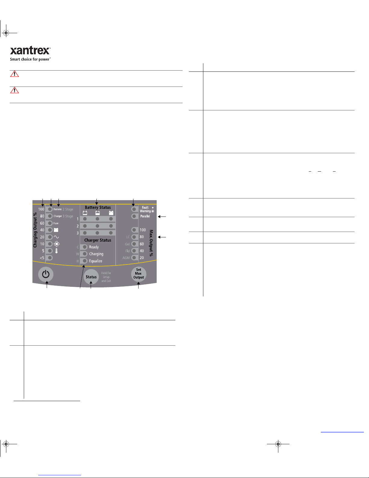
Figure 1
Truecharge2 Remote Panel
Item Description
1 ON/STANDBY Button
• Press to enable or disable the charger while AC power is connected.
• When in Setup Mode: Press to select the Charger Mode: two or three-stage.
• To set or cancel an Equalization program: Press and hold both the Statu s and
ON/STANDBY
buttons for mo
re than five seconds.
2 Charging Output (%) LEDs
• The LEDs illuminate like a bar graph displaying the present total output charge current as
a
percentage of the maximum rated charge current. For example, unit model TC4012 has a
maximum rated charge current of 40 A so at 60% the charger’s current output is 24 A. The
numbers to the left of the LEDs represent the percentage values (see 2a).
NOTE: When the maximum Charge Output current is limited by pressing the Set Max Output
button, the LEDs will still display the total charge output current as a percentage of the
maximum charge current and NOT as a percentage of the limited charge current.
• An LED may flash intermittently in combination with a solid Fault LED to indicate a fault or
with a flashing Fault LED to indicate a warning condition. The icons on the right side of the
LEDs represent different types of faults and warnings.
1
2a 2 6a 4 6
8
953
7
3 Charger Status LEDs
Displays the present status of the charger.
• Ready - a solid light indicates that all batteries are fully charged and in rest stage.
• Ready and Charging - solid lights indicate that batteries are fully charged and in float stage.
• Charging - a solid light indicates that the charger is performing a normal charge cycle.
• Equalize - a solid light indicates that the charger is performing an equalization cycle.
- a flashing light indicates that the equalization cycle will begin after the absorption
stage is done.
4 Battery Status LEDs
Displays the present status of each battery (or battery bank) – available only on the Remote Panel.
Each row represents the battery (or battery bank) number designation—1, 2, or 3. Each column
represents Low, Medium, or Full battery capacity.
NOTE: These levels are measured and the status updated at the start of each stage in the charge
cycle during charging, on demand when AC is disconnected and the Status button is pressed, or
whenever AC is cycled.
• Low if battery voltage is below 11.9 V (23.8 V for 24 Vdc systems)
• Medium if the voltage is 11.9 to 12.4 V (23.8 to 24.8 V for 24 Vdc systems)
• Full if the voltage is above 12.4 V (24.8 V for 24 Vdc systems)
5 Status Button
NOTE: The LEDs will flash intermittently when the Remote goes into Setup Mode.
• Press and hold for five seconds to enter Setup Mode.
• When in Setup Mode: Press to select the Battery Temperature: C
old, Warm, or Hot.
NOTE: If the optional BTS
a
is used, the battery temperature setting is adjusted automatically.
• Press and hold for five seconds to save settings and exit Setup Mode.
• When setting or cancelling an Equalization cycle or program: Press and hold both the St atus
and
ON/STANDBY buttons.
• When AC is disconnected: Press to view battery status.
6 Fault/Warning LED
The LED displays a solid light to indicate a fault condition or flashes intermittently to indicate a
warning condition. Faults or warnings are displayed in combination with a flashing Charging
Output (%) LED to indicate the type of fault or warning (6a).
7 Parallel LED
The LED illuminates a solid light indicating that two Truecharge2 Battery Chargers are in parallel
configuration.
8 Max. Output (%) LED
The LED illuminates a solid light corresponding to the Maximum Charger Output % setting.
9 Set Max Output Button
• Press to select and limit the maximum charge current. For example, the unit model TC401
2
has a maximum charge current of 40 A. Changing the Max Output setting from 100 to 80 will
limit the maximum charge current to 32 A (80% of 40 A). It will also limit the equalization
current if the Max Output is set to below 50%. This feature is available only on the Remote
Panel.
• When in Setup Mode: Press to select the Battery Type: AGM, Flooded, GEL, or LeadCalcium.
NOTE: The OEM battery type setting is also available if a custom setting has been programmed
by Xantrex or a designated OEM and is indicated when all four battery type LE
Ds are
illuminated.
a. Battery Temperature Sensor (to order reference part number: 808-0232-01)
Item Description
975-0373-01-02_Rev-A(TC2 Remote Panel Parallel).fm Page 1 Wednesday, December 8, 2010 9:40 AM
Boating & Marine
Page 2
Technical Specifications
NOTE: Specifications are subject to change without prior notice.
DC input voltage range +10.5–15 Vdc
Operating DC voltage range +9–15 Vdc
Input current range 30 mA (60 mA at LED test)
Operating ambient temperature 0–50 °C
Dimensions (L×W×H) 4
9
/16 × 13/4 × 39/16 in. (114.64 × 44.39 × 89.64 mm)
975-0373-01-02_Rev-A(TC2 Remote Panel Parallel).fm Page 2 Wednesday, December 8, 2010 9:40 AM
Configuring the Charger Mode
NOTE: By default, the Charger Mode is set to three-stage.
1. Press and hold the Stat us button for five seconds to enter Setup mode. Entering Setup mode will enable you to
select the charger mode.
2. Press on/standby button to select the desired charger mode.
The LEDs will indicate which of the two types is being selected: three-stage (default) or two-stage.
3. Press and hold the Stat us button for five seconds to exit Setup mode and save the new setting.
Configuring the Battery Bank Type
NOTE: By default, the Battery Type is set to Flooded.
1. Press and hold the Stat us button for five seconds to enter Setup mode. Entering Setup mode will enable you to
select the battery type.
2. Press Set Max Output button to select the proper battery type.
The LEDs will indicate which of the four types is being selected: Flooded (default), GEL, Lead Calc., or AGM.
NOTE: If a custom battery type has been programmed by the OEM, then all four LEDs will light up to indicate a
fifth type. To select the OEM battery type, use the Truecharge2 Battery Charger control panel.
3. Press and hold the Stat us button for five seconds to exit Setup mode and save the new setting.
Configuring the Maximum Output Current Percentage of the Charger
NOTE: By default, the Max. Output % is set to 100.
• Press the Set Max Output button to select the appropriate maximum output setting.
The LEDs will indicate which of the five values is being selected: 100, 80, 60, 40, or 20.
NOTE: The equalization charge current may be affected. See note under Description for Set Max Output
Button.
NOTE: If operating two Truecharge2 Battery Chargers in parallel, configuration settings made via the remote
panel or primary charger will be applied to both chargers. Settings cannot be changed via the secondary
charger.
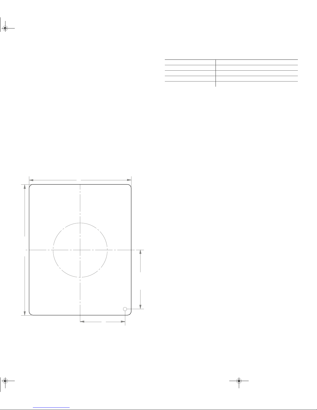
Mounting Template
Figure 2
Truecharge2 Remote Panel Mounting Template (1:1)
114.64 mm
3mm
48 mm
89.64 mm
39.42 mm
51.92 mm
Xantrex, Truecharge,
and Smart choice for power are trademarks of Schneider Electric Services International sprl, registered in the U.S. and other countries. Other trademarks, registered trademarks, and product names are the property of their
respective owners and are used herein for identification purposes only. Truecharge2 Remote Panel Installation Instructions, Xantrex Technology USA Inc. (“Xantrex”): (A) MAKES NO WARRANTY AS TO THE ACCURACY, SUFFICIENCY OR SUITABILITY
OF ANY TECHNICAL OR OTHER INFORMATION PROVIDED IN ITS MANUALS OR OTHER DOCUMENTATION, (B) ASSUMES NO RESPONSIBILITY OR LIABILITY FOR LOSSES, DAMAGES, COSTS OR EXPENSES, WHETHER SPECIAL, DIRECT, INDIRECT, CONSEQUENTIAL
OR INCIDENTAL, WHICH MIGHT ARISE OUT OF THE USE OF SUCH INFORMATION. THE USE OF ANY SUCH INFORMATION WILL BE ENTIRELY AT THE USER’S RISK; AND (C) REMINDS YOU THAT IF THIS MANUAL IS IN ANY LANGUAGE OTHER THAN ENGLISH,
ALTHOUGH STEPS HAVE BEEN TAKEN TO MAINTAIN THE ACCURACY OF THE TRANSLATION, THE ACCURACY CANNOT BE GUARANTEED.
 Loading...