

Page 1
INSTALLATION
INSTRUCTIONS
XVCE100IR
Volume Control, Electronic, 100W, IR
Page 2

Installation Instructions
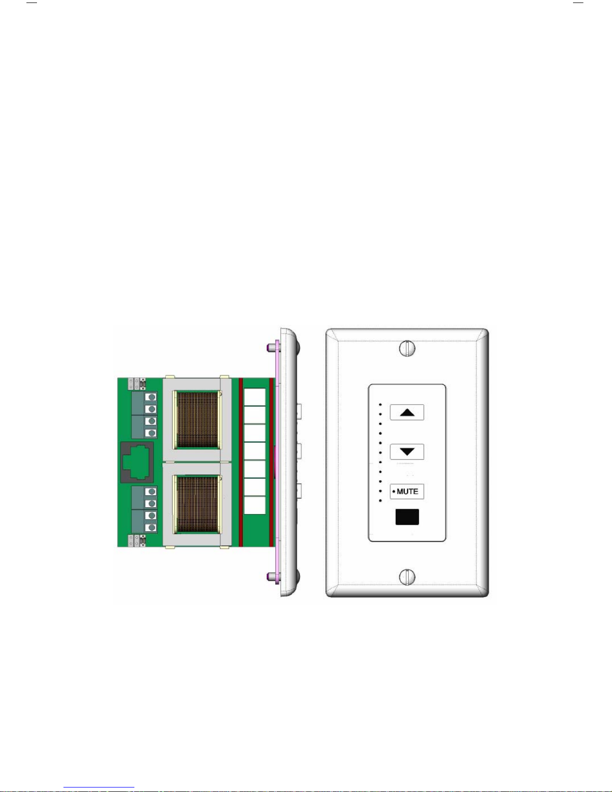
XVCE100IR Volume Control
The XVCE100IR is a volume control that provides the touch and
feel of an electronic device. With a high-value appeal, no
mechanical rotating or sliding parts are used in this high-power
volume control design. The XVCE100IR is rated to 100 Watts and
provides 12 steps of volume control. Also featured is a built-in IR
eye and “mute” button. The XVCE100IR comes with mounting
screws and a Decora
®
style insert that can be used with the popular
Decora® faceplate.
Features and Benefits
Power Handling:100 W/channel RMS
Frequency Response: 20Hz to 20kHz ± 0.5 dB
THD+N: < 1%
Impedance Settings: 1X / 2X / 4X
Minimum Speaker Load: 4 Ohms
Override Current Draw: 0.75mA (logic only)
Sense Current Draw: 25mA
Maximum Current Draw: 40mA
Operating Voltage: 12 Volts DC
Sense Voltage: 9-12 Volts DC
Override Voltage: 9-12 Volts DC
Mounting: Minimum 18 cu. in. J-box or Mud Ring.
Note: Be sure to check fit before choosing J-boxes!
Page 3

Installation, Notes, and Caution
You will need at the very least, a 1/8” slotted screwdriver, a ¼”
slotted screwdriver, wire cutters and wire strippers.
The recommended speaker wire to be used is 16-gauge stranded
copper speaker wire. For runs longer than 100 feet, we recommend
14-gauge stranded copper speaker wire. Never use solid-core wire
such as aluminum or Romex wire.
Most installations in the United States require a special fire rated
wire (CL-2 or CL-3) for speaker wire installed within a wall. Consult
your local building codes to find out what kind of wire is required.
Be sure to observe proper polarity when connecting a system. The
positive terminals should always be connected to the positive wire.
The negative terminals should always be connected to the negative
wire. Failure to do so will result in poor phasing and possible
system malfunctions.
Some areas allow the installation of the volume control to be placed
in the same junction box as a high voltage connection (120VAC)
and divided by a low-voltage partition. This is not recommended as
the speaker wires may pick up interference from the high voltage
(120VAC) power lines. Again, consult your local building codes to
verify the proper way to install the product.
Page 4

Impedance Jumper Settings for Identical Impedance
How to use the impedance jumper setting chart:
1) Determine the minimum amplifier impedance (typically either 4or 8-Ohm). This information can usually be found next to the
speaker outputs located on the receiver or amplifier. If in doubt,
consult the receiver and/or amplifier instruction manual.
2) Next, determine the impedance of a single speaker that will be
used. Use the left-most column.
3) Move to the right of the chart and find the number of speaker
pairs that you plan to connect to the volume control.
4) Finally, move up the column to the very top row. This row will
provide the jumper setting solution. Change the jumper on the
volume control to complete the impedance jumper setting
procedure. (Factory setting is X4)
Jumper Settings
x1 x2 x4
8
Ohm
1 PAIR 2 PAIRS 4 PAIRS
6
Ohm
- 1 PAIR 2 PAIRS
Speaker
Impedance
4
Ohm
- 1 PAIR 2 PAIRS
CHART A: 8 Ohm Minimum Amplifier
Jumper Settings
x1 x2 x4
8
Ohm
1 PAIR 4 PAIRS 8 PAIRS
6
Ohm
1 PAIR 2 PAIRS 4 PAIRS
Speaker
Impedance
4
Ohm
1 PAIR 2 PAIRS 4 PAIRS
CHART B: 4 Ohm Minimum Amplifier
Page 5

Basic Connection
FIGURE 1
Page 6

FIGURE 1 shows the most basic connection. A power supply must
be connected to the XVCE100IR. The credit card remote (included)
can still be used. However, no IR bus is established to control
source components.
The 781RG Power Supply should be connected to the XVCE100IR
Volume Control as follows.
XVCE100IR RJ45 781RG POWER SUPPLY
PIN 6 (White/Green) +12VDC
PIN 8 (Brown) GROUND
Installation Tip – Setting the Volume
1) Set your receiver and/or amplifier to the lowest possible
volume setting.
2) Turn the XVCE100IR volume control to maximum volume
(press up arrow).
3) Turn up the receiver and/or amplifier volume setting until you
reach the maximum listening level desired.
4) Finally, lower the XVCE100IR volume control level (press
down arrow). Volume setting is now complete.
RJ45 Connections
Page 7

IR System Connection
FIGURE 2
Page 8

FIGURE 2 shows a more advanced connection. In this application,
an IR bus is established. Now almost any remote control can be
directed at the XVCE100IR to control the source components.
XVCE100IR RJ45 789-44 Connecting Block
PIN 6 (White/Green) +12VDC
PIN 8 (Brown) GROUND
PIN 3 (Orange) IR
PIN 2 (White/Blue) IR
Speaker Connections
Page 9

Other Connections
Override: Allows Page/Doorbell signals to override the volume
setting in the XVCE100IR. A HIGH signal will place the XVCE100IR
into a preset volume level. To preset the volume level, find the
desirable volume level with the up and down buttons. Press and
hold the MUTE button. While holding down the MUTE button, press
and hold the VOLUME UP button. When the POWER SENSE LED
starts to blink, the override level is set.
Sense: When no voltage is found on the sense line, the
XVCE100IR will be in MUTE condition upon power up. Pressing
any button will take the XVCE100IR out of MUTE condition.
Page 10

Xantech Corporation
13100 Telfair Avenue, 2/F
Sylmar, CA 91342
Installation Instructions, XVCE100IR
© 2007 Xantech Corporation, Document #9801339B
This document is copyright protected. No part of this manual may be copied or reproduced in any
form without prior written consent from Xantech Corporation.
Xantech Corporation shall not be liable for operational, technical, or editorial errors/omissions made
in this document.
 Loading...