

Page 1
XT-HDBT-MX44-4K-KIT USER MANUAL
10019309 REV-A0
®
© 2018 XANTECH® is a registered trademark of Nortek Security & Control.
User Manual
XT-HDBT-MX44-4K-KIT
Our XT-HDBT-MX44-4K-KIT 4x4 HDBaseT™ Matrix offers unprecedented performance and value for the custom installation market. The XT-
HDBT-MX44-4K-KIT is a 4K HDCP 2.2 Matrix package, delivering HDMI, Bi-directional IR and PoH (PoE) up to lengths of 70m over a single CAT
cable. The Matrix also provides advanced features including simultaneous HDBaseT™/HDMI on output 1 and a web browser interface module for
control and configuration of the matrix. The XT-HDBT-MX44-4K-KIT is supplied with 4 x XT-HDBT-EX70-4K-RX Receivers.
Introduction
Key Features
• Advanced HDBaseT™ technology offering uncompressed video and audio with zero latency
• Features 4x HDMI inputs which can be independently routed to 4x HDBaseT™ outputs
• Output 1 features simultaneous HDMI and HDBaseT™ output
• Extends HDMI up to a distance of 70m over single CAT cable
• Supports 4K UHD video up to 40m (3840 x 2160 @30Hz 4:4:4, 4096 x 2160 @24Hz 4:4:4, and 4K @60Hz 4:2:0)
• Supports all known HDMI audio formats including Dolby TrueHD, Dolby Atmos, Dolby Digital Plus and DTS-HD Master Audio Transmission
• Web interface module for control and configuration of Matrix
• Supports bi-directional IR on all HDBaseT outputs
• Control via front panel , IR, RS-232 and TCP/IP
• 1U Design for 19” rack mount integration - Mounting kit included
• Advanced EDID management
• HDCP 2.2
Page 2

XT-HDBT-MX44-4K-KIT USER MANUAL
www.xantech.com
®
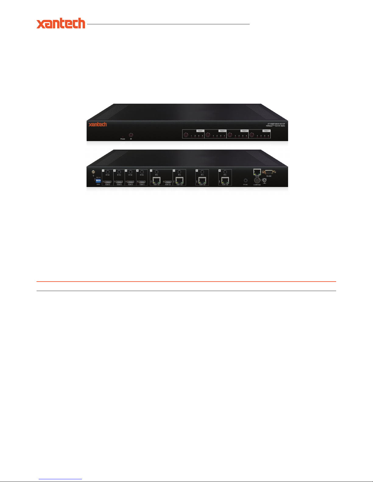
Panel Description
XT-HDBT-MX44-4K Front Panel
IR receiver window for matrix control
Power LED indicator - indicates if the unit is on or off
1
2
3
1 2
XT-HDBT-MX44-4K Rear Panel
IR output - connect to Xantech IR emitter for source control from
HDBT receivers
IR input - connect to Xantech IR receiver to transmit IR
to HDBT receivers
HDMI output - connect to a HDMI display
TCP/IP (RJ45) – connect to LAN for TCP/IP control of
Matrix
RS-232 Serial port for control by third party control devices
EDID DIP switch used to adjust HDMI input EDID settings
HDMI inputs - connect to HDMI source devices
HDBT output - RJ45 connector, connect to
XT-HDBT-EX70-4K-RX receivers
IR input for matrix control
Power port - use included 24V/3.5A DC power adaptor
4
5
9
10
9
6
7
11
3
HDMI output selection buttons 1-4. Press to scroll through
source inputs per HDMI output
12 13
8
12
13
HDMI Link LED - LED will be lit when an active HDMI connection
is detected.
HDMI Output - Connect to the HDMI input on local display device
IR input - Connect to Xantech 12V IR Receiver (sold separately).
Connection is used extend IR over the HDBaseT signal to control
device located at the XT-HDBT-SP14-4K splitter.
IR output - Connect to Xantech 12V Emitter (sold separately).
Connection is used to control the local source or display device
from Xantech IR Receiver connected at the XT-HDBT-SP14-4K
splitte r.
Power LED indicator.
Power port - Connect Xantech 12V DC power supply only. Note -
HDBaseT extender kit can be powered from either the Transmitter
or Receiver by using the power over cable (POH) feature.
HDBaseT input - RJ45 connector. Connect to HDBaseT output on
XT-HDBT-SP14- 4 K split ter.
HDBaseT Link LED - LED will be lit when an active connection is
established with the XT-HDBT-SP14-4K.
XT-HDBT-EX70-4K-RX
16
17
18
19
21
22
23
16 18 19
20
22 2317
21
20
HDMI Out
Link
Power
IR IN IR OUT
12V
2A
HDMI Out
Link
Power
IR IN IR OUT
12V
2A
HDBT In
Link
4 5 6 7 8
10 11
XT-HDBT-MX44-4K-KIT
HDBaseT™ 4x4 4K Matrix
Power IR
1 2 3 41 2 3 41 2 3 41 2 3 4
Output 4Output 3Output 2Output 1
XT-HDBT-MX44-4K-KIT
HDBaseT™ 4x4 4K Matrix
Power IR
1 2 3 41 2 3 41 2 3 41 2 3 4
Output 4Output 3Output 2Output 1
1 2 3 4 1 432
EDID
RS-232TCP/IP
IR Ext.
HDBT Out
POH
IR In
HDBT Out
POH
IR In
HDBT Out
HDMI Out
POH
HDBT Out
POH
Link
HDMI In
Link
IR InIR In
IR Out
HDMI In
Link
IR Out
HDMI In
Link
IR Out
HDMI In
Link
IR Out
24V 3.5A
3 2 1 0
0
1
Page 3
XT-HDBT-MX44-4K-KIT USER MANUAL
10019309 REV-A0
®
© 2018 XANTECH® is a registered trademark of Nortek Security & Control.
5V 1A
EDID
3 2 1 0
0
1
XT-SW41-4K18G
IR
EDID (Extended Display Identification Data) is a data structure that is used between a display and a source. This data is used by the source to find
out what audio and video resolutions are supported by the display then from this information the source will discover what the best audio and video
resolutions need to be outputted.
While the objective of EDID is to make connecting a digital display to a source a simple plug and play procedure issues do arise when multiple
displays or video matrix switching is introduced because of the increased number of variables.
By pre-determining the video resolution and audio format of the source and display device you can reduce the time need for EDID hand shaking
thus making switching quicker and more reliable.
Configuration of Matrix EDID settings can be achieved in one of the following ways:-
1 Using the EDID dip-switches located on the rear of the Matrix
2 Using the Supplied Matrix IR Remote Control
3 Using the web browser interface
Adjusting The EDID Settings
[DIP]=0000: HDMI 1080p@ 60Hz, Audio 2ch PCM
[DIP]=0001: HDMI 1080p@60Hz, Audio 5.1ch PCM/DTS/DOLBY
[DIP] = 0010 : HDMI 1080p@60Hz, Audio 7.1ch PCM/DTS/DOLBY/HD
[D I P ] = 0011: HDMI 1080i@60Hz, Audio 2ch PCM
[DIP] = 010 0 : HDMI 1080i@60Hz, Audio 5.1ch PCM/DTS/DOLBY
[DIP]=0101: HDMI 1080i@60Hz, Audio 7.1ch PCM/DTS/DOLBY/HD
[D I P ] = 0110 : HDMI 4K@60Hz 4:2:0+4K@30Hz 4:4:4, Audio 2ch PCM
[D I P ] = 0111: HDMI 4K@60Hz 4:2:0+4K@30Hz 4:4:4, Audio 5.1ch PCM/DTS/DOLBY
[DIP]=1000: HDMI 4K@60Hz 4:2:0+4K@30Hz 4:4:4, Audio 7.1ch PCM/DTS/DOLBY/HD
[DIP] =1001: HDMI 4K@30Hz 4:4:4, Audio 2ch PCM
[DIP] =1010 : HDMI 4K@30Hz 4:4:4, Audio 5.1ch PCM/DTS/DOLBY
[D I P ] =10 11 : HDMI 4K@30Hz 4:4:4, Audio 7.1ch PCM/DTS/DOLBY/HD
[D I P ] =110 0 : DVI 1280x1024@60Hz, Audio None
[D I P ] =110 1 : DVI 1920x1080@60Hz, Audio None
[D I P ] =1110 : DVI 1920x1200@60Hz, Audio None
[D I P ] =1111: Software Control EDID
EDID Dip-switches
Dip-switch position ‘0’ = Off
Dip-switch position ‘1’ = On
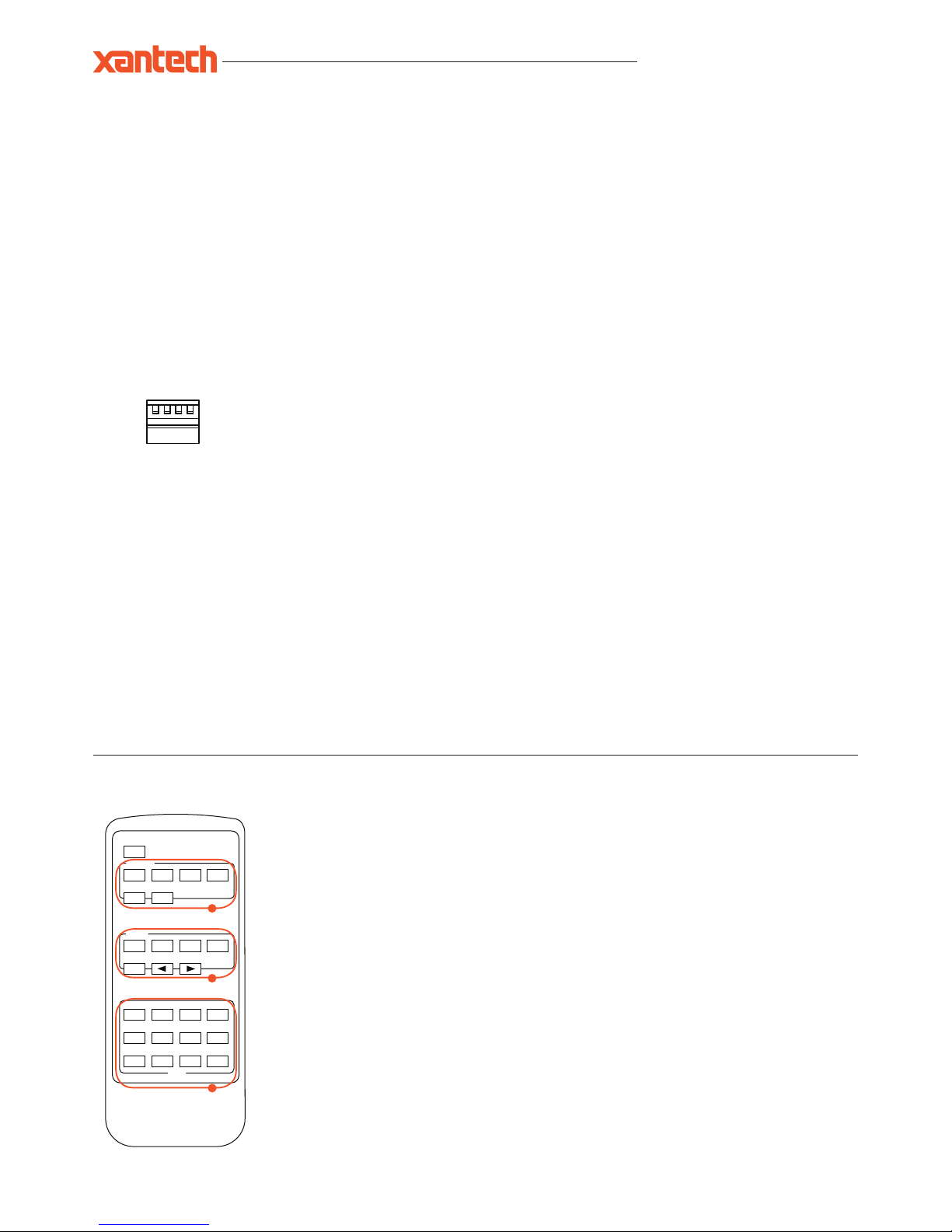
Remote Control Description
OUTPUT AND INPUT SELECTION
A Selects the zone OUTPUT (1 - 4) you wish to
change the source on
B Selects the source INPUT (1 - 4) you wish to
change on the selected zone
EXAMPLE: To switch source 2 to zone 4 you would
press Ouput 4 (A) followed by pressing Input 2 (B ).
ALL button: The all button selects all the inputs or
outputs in its corresponding box. Example: (The “All”
button in the Output box selects all the zones so all
zones will change to what source input is selected next)
PTP: This button will align all zone outputs with the like
numbered source inputs. Example: Input 1 to output 1,
input 2 to output 2, etc
NOTE: BUT TON PRESS SEQUENCE MUST BE
FINISHED IN 5 SECONDS, OTHERWISE THE
OPERATION IS DISCARDED
EDID SET UP
The matrix provides a comprehensive range of EDID
settings. Below are three examples of how to deploy the
desired EDID setting when using the supplied remote.
A. Fix EDID to an Input or ALL inputs: Press the
desired video resolution button (1080I / 1080P / 3D
/ 4K), then select the desired audio format (2.0CH
/ 5.1CH / 7.1CH), then select the source input you
want this EDID information allocated to by pressing
the INPUT 1 – 4 or the ALL button
B. Copy EDID of Output-X to an Input or ALL: Press
the COPY button then select the OUTPUT you wish
to copy the EDID information from, then select
the source input you want to copy this EDID to by
selecting the INPUT 1-4 or the ALL button.
C. User defined EDID to an Input or ALL inputs:
Press USER1 / USER2 button then select the
source you wish to assign this EDID to by selecting
INPUT 1-4 or the ALL button
POWER
OUTPUT
INPUT
1 2 3 4
1 2 3 4
1080I
2.0CH
USER 1 USER 2 FN1 FN2
EDID
5.1CH 7.1CH COPY
1080P 3D 4K
ALL
PTPALL
B
A
C
Page 4
XT-HDBT-MX44-4K-KIT USER MANUAL
www.xantech.com
®
Understanding the HDBaseT status lights
Xantech HDBaseT solutions include LED indicators to show connectivity and help diagnose possible problems.
Xante ch X T-HDBT-M X44-4K
• The Yellow HDBaseT status link light will be off when the zone output has been turned off or there is a problem with the specific Matrix output.
• The Yellow HDBaseT status link light will blink when the zone output is on and working.
• The Green HDBaseT link light will blink if there is an unstable connection between the Matrix and HDBaseT Receiver.
• The Green HDBaseT link light will be lit when a there is an active HDBaseT Receiver connected to the Matrix.
• The Green HDBaseT link light will be off when a there is no connection with a HDBaseT receiver.
Xantech XT-HDBT-EX70-4K-RX
• The HDMI link light will be off when there is no connection with a display.
• The HDMI link light will be on when there is an active connection with a display.
• The HDBaseT link light will be off when there is no CAT cable/active HDBaseT connection on the RJ45 HDBaseT input.
• The HDBaseT link light will blink if there is an unstable connection between the Matrix and HDBaseT receiver.
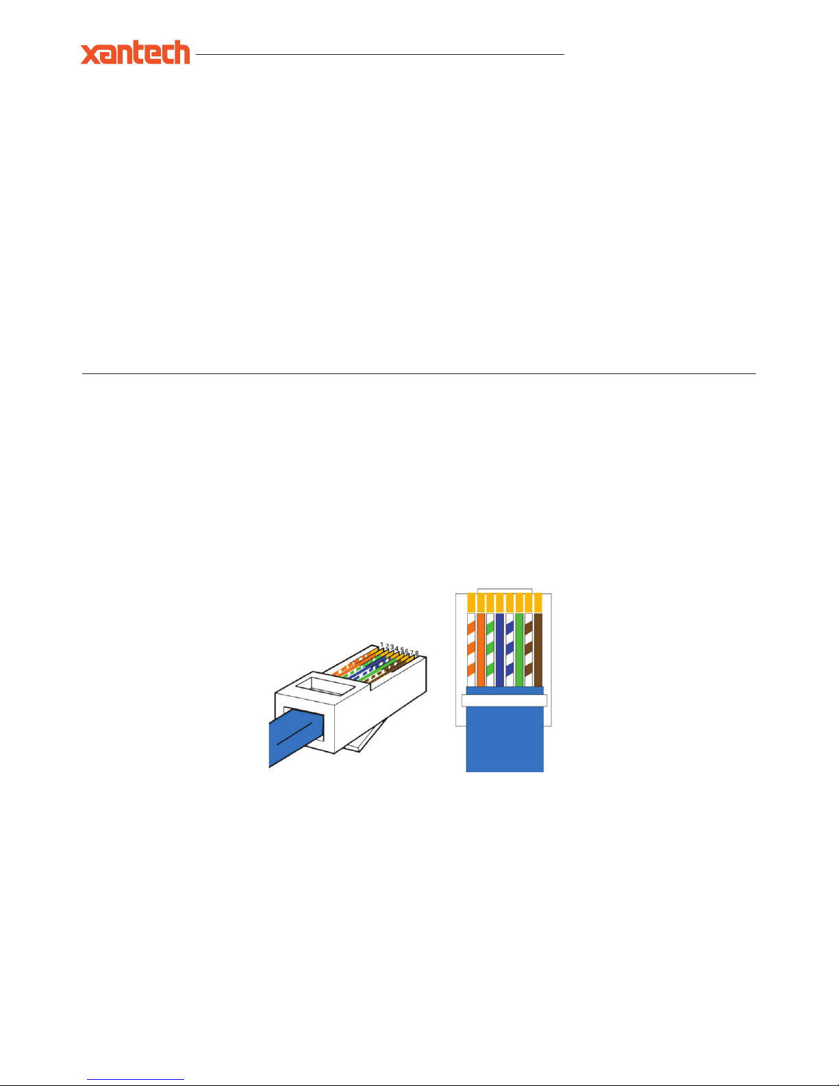
Terminating HDBaseT CAT cable
It is important that the interconnecting CAT cable between the ELAN HDBaseT products is terminated using the correct RJ45 pin configuration. The
link CAT cable MUST be a ‘straight’ (pin-to-pin) CAT cable and it is advised that this is wired to the T568B wiring standard as this format is less
prone to EMI (Electro-Magnetic Interference).
When installing CAT cables it is advised that you use the best possible CAT cable quality possible. HDMI distribution products will only work if used
with CAT5e standard cable or above. ELAN recommends using a CAT6 cable for your installations, especially when running over longer distances,
in areas of high EMI, or with 4K signal distribution. It is advised that using any method of patch panel, wall plate or join in the CAT cable is avoided
as these will result in HDBaseT signal degradation. ELAN also recommend using the best quality RJ45 connectors possible.
RJ45 Pin-Out
T568B
12345678
Page 5

XT-HDBT-MX44-4K-KIT USER MANUAL
10019309 REV-A0
®
© 2018 XANTECH® is a registered trademark of Nortek Security & Control.
The XT-HDBT-MX44-4K Matrix main communication ports are located on the rear panel and includes the following connections:
Connections:
IR output - 3.5mm mono jack provides routed IR emitter
IR input - 3.5mm stereo jack provides zone specific routed IR receiver input
IR input for matrix control
TCP/IP RJ45 socket for Web Interface control
RS-232 Serial port - For control of switcher by third party control devices
TCP/IP
The XT-HDBT-MX44-4K Matrix can be controlled via TCP/IP.
For the full list of protocols please see ' RS-232 and Telnet Commands' located at the rear of this manual.
The Matrix features a built-in web browser user interface allowing control and configuration of the matrix.
A ‘Straight-through’ RJ45 patch lead should be used.
RS-232 2-Way
The Matrix can be controlled via a 9-pin serial cable.
For the full list of protocols please see 'RS-232 and Telnet Commands' located at the rear of this manual.
Details of RS-232 pin assignment and communication are adjacent. Please note that depending on your control device serial port pin configuration
you may require either a ‘Straight’ RS-232 cable or ‘Null-modem’ type.
Control Ports
XANTECH RS-232 REMOTE CONTROL
CONSOLE
PIN Assignment PIN Assignment
1 NC 1 NC
2 Tx 2 Rx
3 Rx 3 Tx
4 NC 4 NC
5 GND 5 GND
6 NC 6 NC
7 NC 7 NC
8 NC 8 NC
9 NC 9 NC
Baud Rate: 57600 bps
Data Bit: 8-bit
Parity: None
Stop Bit: 1-bit
Flow Control: None
1 2 4 5
XT-HDBT-MX44-4K-KIT
HDBaseT™ 4x4 4K Matrix
Power IR
1 2 3 41 2 3 41 2 3 41 2 3 4
Output 4Output 3Output 2Output 1
1 2 3 4 1 432
EDID
RS-232TCP/IP
IR Ext.
HDBT Out
POH
IR In
HDBT Out
POH
IR In
HDBT Out
HDMI Out
POH
HDBT Out
POH
Link
HDMI In
Link
IR InIR In
IR Out
HDMI In
Link
IR Out
HDMI In
Link
IR Out
HDMI In
Link
IR Out
24V 3.5A
3 2 1 0
0
1
3
Page 6

XT-HDBT-MX44-4K-KIT USER MANUAL
www.xantech.com
®
RS-232 and Telnet Commands
The Matrix can be controlled via serial and TCP/IP. The following pages list all available serial commands for the Matrix.
Details of RS-232 pin assignment can be found on the previous page.
Commonly used Serial commands:
There are several commands that are commonly used for control and testing:-
STATUS Status will give feedback on Matrix such as zones on, type of connection etc
PON Power on
POFF Power off
OUTxxON (xx is the zone number you wish to turn on)
Example:- OUT01ON (This would turn output one back on)
OU Tx xFRyy (xx is the zone out, yy is the input)
Example:- OUT01FR04 (This would switch output 1 to source input 4)
Common Mistakes
• Carriage return – Some programs do not require the carriage return where as other will not work unless sent directly after the string. In the
case of some Terminal software the token <CR> is used to execute a carriage return. Depending on the program you are using this token maybe
different. Some other examples that other control systems deploy include \r or 0D (in hex)
• Spaces – Blustream commands do not require space between commands unless specified. There may be some programs that require spacing
in order to work.
- How the string should look is as follows OUT01ON
- How the string may look if spaces are required: OUT{Space}01{Space} ON
• Baud rate or other serial protocol settings not correct
RS-232 COMMAND DESCRIPTION
? Print Help Information
HELP Print Help Information
STAT US Print System Status And Port State
PON Power On, System Run On Normal State
POFF Power Off, System Run On Power Save State
IR ON/OFF Set System IR Control On Or Off
KEY ON/OFF Set System Key Control On or Off
BEEP ON/OFF Set System Deep On Or Off
LED ON/OFF
Set Front Panel LED Always On
Or Auto Turn Off In Power On State
RSB X
Set RS-232 Baud Rate to X bps
x=[0:115200, 1:57600 2:38400, 3:19200, 4:9600, 5:4800]
RESET Reset System To Default Setting
RESET ALL
Reset System And Network To Default Configuration
(Should Type “Yes” To Confirm, “No” To Discard)
OUT xx ON/OFF Set Output:xx On or Off
OUT xx FR yy
Set Ouput:xx From Input:yy
xx= 00: Select All Output Ports
xx= [01...04]: Select One Output Port
yy=[01...04]: Select One Input Port
POH xx ON/OFF
Set Output:xx POH On Or Off
xx= 00: Select All Output Ports
xx= [01...04]: Select One Output Port
yy=[01...04]: Select One Input Port
Page 7

XT-HDBT-MX44-4K-KIT USER MANUAL
10019309 REV-A0
®
© 2018 XANTECH® is a registered trademark of Nortek Security & Control.
RS-232 COMMAND DESCRIPTION
EDID xx CP yy Set Input:xx EDID Copy From Output:yy
EDID xx DF zz
Set Input:xx EDID To Default EDID:zz
xx= 00: Select All Input Port
xx= [01...04]: Select One Input Port
yy=[01...04]: Select One Output Port
zz=00: HDMI 1080p@ 60Hz, Audio 2CH PCM
zz=01: HDMI 1080p @ 60Hz, Audio 5.1CH DTS/DOLBY
zz=02: HDMI 1080p@60Hz, Audio 7.1CH DTS/DOLBY/HD
zz=03: HDMI 1080i@60Hz, Audio 2CH PCM
zz=04: HDMI 1080i@60Hz, Audio 5.1CH DTS/DOLBY
zz=05: HDMI 1080i@60Hz, Audio 7.1CH DTS/DOLBY/HD
zz=06: HDMI 1080p@ 60Hz/3D, Audio 2CH PCM
zz=07: HDMI 1080p@60Hz/3D, Audio 5.1CH DTS/DOLBY
zz=08: HDMI 1080p @60Hz/3D, Audio 7.1CH DTS/DOLBY/HD
zz=09: HDMI 4K@30Hz 4:4:4, Audio 2CH PCM
zz=10: HDMI 4K@30Hz 4:4:4, Audio 5.1CH DTS/DOLBY
zz=11: HDMI 4K@30Hz 4:4:4, Audio 7.1CH DTS/DOLBY/HD
zz=12: DVI 1280x1024@ 60Hz, Audio None
zz=13: DVI 1920x1080@ 60Hz, Audio None
zz=14: DVI 1920x1200@ 60Hz, Audio None
zz=15: User EDID 1
zz=16: User EDID 2
zz=17: GUI Download EDID
zz=18: HDMI 4K@60Hz 4:2:0, Audio 2CH PCM
zz=19: HDMI 4K@60Hz 4:2:0, Audio 5.1CH DTS/DOLBY
zz=20: HDMI 4K@ 60Hz 4:2:0, Audio 7.1CH DTS/DOLBY/HD
PRESE T STATUS Print Preset Config Status
PRESET pp SET aa,bb,cc,dd Set Preset:pp Config
PRESET pp SAVE Save Current Output Connection To Preset:pp Config
PRESET pp APPLY
Apply Preset:pp Config To Output Connection
pp= [01..08]: Select Preset Index
aa=[01..04]: Output 01 From aa, [00]: Not Set
bb: Output 02 ... dd: Output 04
NET DHCP ON/OFF Set Auto IP( DHCP) ON Or OFF
NET IP xxx.xxx.xxx.xxx Set IP Address
NET GW xxx.xxx.xxx.xxx Set Gateway Address
NET SM xxx.xxx.xxx.xxx Set Subnet Mask Address
NET RB Set Network Reboot and Apply New Config
NET TN xxxx Set Telnet Port
Page 8

XT-HDBT-MX44-4K-KIT USER MANUAL
www.xantech.com
®
4x4 Matrix IR Database
4X4 MATRIX PRODUCTS NEC IR: CUSTOMER CODE 1898 HEX IR
POWER 14
0000 006D 0000 0022 0157 00AC 0016 0016 0016 0016 0016 0016 0016 003F 0016 003F 0016 0016
0016 0016 0016 0016 0016 0016 0016 0016 0016 0016 0016 003F 0016 003F 0016 0016 0016 0016
0016 003F 0016 0016 0016 0016 0016 003F 0016 0016 0016 003F 0016 0016 0016 0016 0016 0016
0016 003F 0016 003F 0016 0016 0016 003F 0016 0016 0016 003F 0016 003F 0016 003F 0016 0689
OUTPUT 1 09
0000 006D 0000 0022 0157 00AC 0016 0016 0016 0016 0016 0016 0016 003F 0016 003F 0016 0016
0016 0016 0016 0016 0016 0016 0016 0016 0016 0016 0016 003F 0016 003F 0016 0016 0016 0016
0016 003F 0016 003F 0016 0016 0016 0016 0016 003F 0016 0016 0016 0016 0016 0016 0016 0016
0016 0016 0016 003F 0016 003F 0016 0016 0016 003F 0016 003F 0016 003F 0016 003F 0016 0689
OUTPUT 2 1D
0000 006D 0000 0022 0157 00AC 0016 0016 0016 0016 0016 0016 0016 003F 0016 003F 0016 0016
0016 0016 0016 0016 0016 0016 0016 0016 0016 0016 0016 003F 0016 003F 0016 0016 0016 0016
0016 003F 0016 003F 0016 0016 0016 003F 0016 003F 0016 003F 0016 0016 0016 0016 0016 0016
0016 0016 0016 003F 0016 0016 0016 0016 0016 0016 0016 003F 0016 003F 0016 003F 0016 0689
OUTPUT 3 1F
0000 006D 0000 0022 0157 00AC 0016 0016 0016 0016 0016 0016 0016 003f 0016 003f 0016 0016
0016 0016 0016 0016 0016 0016 0016 0016 0016 0016 0016 003f 0 016 003f 0 016 0016 0016 0016
0016 003f 0 016 003f 0 016 003f 0016 003f 0016 003f 0016 003f 0016 0016 0016 0016 0016 0016 0016
0016 0016 0016 0016 0016 0016 0016 0016 0016 0016 003f 0016 003f 0016 003f 0016 0689
OUTPUT 4 0D
0000 006D 0000 0022 0157 00AC 0016 0016 0016 0016 0016 0016 0016 003F 0016 003F 0016 0016
0016 0016 0016 0016 0016 0016 0016 0016 0016 0016 0016 003F 0016 003F 0016 0016 0016 0016
0016 003F 0016 003F 0016 0016 0016 003F 0016 003F 0016 0016 0016 0016 0016 0016 0016 0016
0016 0016 0016 003F 0016 0016 0016 0016 0016 003F 0016 003F 0016 003F 0016 003F 0016 0689
OUTPUT ALL 19
0000 006D 0000 0022 0157 00AC 0016 0016 0016 0016 0016 0016 0016 003F 0016 003F 0016 0016
0016 0016 0016 0016 0016 0016 0016 0016 0016 0016 0016 003F 0016 003F 0016 0016 0016 0016
0016 003F 0016 003F 0016 0016 0016 0016 0016 003F 0016 003F 0016 0016 0016 0016 0016 0016
0016 0016 0016 003F 0016 003F 0016 0016 0016 0016 0016 003F 0016 003F 0016 003F 0016 0689
OUTPUT PTP 18
0000 006D 0000 0022 0157 00AC 0016 0016 0016 0016 0016 0016 0016 003F 0016 003F 0016 0016
0016 0016 0016 0016 0016 0016 0016 0016 0016 0016 0016 003F 0016 003F 0016 0016 0016 0016
0016 003F 0016 003F 0016 003F 0016 0016 0016 003F 0016 003F 0016 0016 0016 0016 0016 0016
0016 0016 0016 0016 0016 003F 0016 0016 0016 0016 0016 003F 0016 003F 0016 003F 0016 0689
INPU T 1 50
0000 006D 0000 0022 0157 00AC 0016 0016 0016 0016 0016 0016 0016 003F 0016 003F 0016 0016
0016 0016 0016 0016 0016 0016 0016 0016 0016 0016 0016 003F 0016 003F 0016 0016 0016 0016
0016 003F 0016 0016 0016 0016 0016 0016 0016 0016 0016 003F 0016 0016 0016 003F 0016 0016
0016 003F 0016 003F 0016 003F 0016 003F 0016 0016 0016 003F 0016 0016 0016 003F 0016 0689
INPU T 2 55
0000 006D 0000 0022 0157 00AC 0016 0016 0016 0016 0016 0016 0016 003F 0016 003F 0016 0016
0016 0016 0016 0016 0016 0016 0016 0016 0016 0016 0016 003F 0016 003F 0016 0016 0016 0016
0016 003F 0016 003F 0016 0016 0016 003F 0016 0016 0016 003F 0016 0016 0016 003F 0016 0016
0016 0016 0016 003F 0016 0016 0016 003F 0016 0016 0016 003F 0016 0016 0016 003F 0016 0689
INPU T 3 48
0000 006D 0000 0022 0157 00AC 0016 0016 0016 0016 0016 0016 0016 003F 0016 003F 0016 0016
0016 0016 0016 0016 0016 0016 0016 0016 0016 0016 0016 003F 0016 003F 0016 0016 0016 0016
0016 003F 0016 0016 0016 0016 0016 0016 0016 003F 0016 0016 0016 0016 0016 003F 0016 0016
0016 003F 0016 003F 0016 003F 0016 0016 0016 003F 0016 003F 0016 0016 0016 003F 0016 0689
INPU T 4 4A
0000 006D 0000 0022 0157 00AC 0016 0016 0016 0016 0016 0016 0016 003F 0016 003F 0016 0016
0016 0016 0016 0016 0016 0016 0016 0016 0016 0016 0016 003F 0016 003F 0016 0016 0016 0016
0016 003F 0016 0016 0016 003F 0016 0016 0016 003F 0016 0016 0016 0016 0016 003F 0016 0016
0016 003F 0016 0016 0016 003F 0016 0016 0016 003F 0016 003F 0016 0016 0016 003F 0016 0689
INPU T AL L 5E
0000 006D 0000 0022 0157 00AC 0016 0016 0016 0016 0016 0016 0016 003F 0016 003F 0016 0016
0016 0016 0016 0016 0016 0016 0016 0016 0016 0016 0016 003F 0016 003F 0016 0016 0016 0016
0016 003F 0016 0016 0016 003F 0016 003F 0016 003F 0016 003F 0016 0016 0016 003F 0016 0016
0016 003F 0016 0016 0016 0016 0016 0016 0016 0016 0016 003F 0016 0016 0016 003F 0016 0689
INPUT BACK 06
0000 006D 0000 0022 0157 00AC 0016 0016 0016 0016 0016 0016 0016 003F 0016 003F 0016 0016
0016 0016 0016 0016 0016 0016 0016 0016 0016 0016 0016 003F 0016 003F 0016 0016 0016 0016
0016 003F 0016 0016 0016 003F 0016 003F 0016 0016 0016 0016 0016 0016 0016 0016 0016 0016
0016 003F 0016 0016 0016 0016 0016 003F 0016 003F 0016 003F 0016 003F 0016 003F 0016 0689
INPU T UP 05
0000 006D 0000 0022 0157 00AC 0016 0016 0016 0016 0016 0016 0016 003F 0016 003F 0016 0016
0016 0016 0016 0016 0016 0016 0016 0016 0016 0016 0016 003F 0016 003F 0016 0016 0016 0016
0016 003F 0016 003F 0016 0016 0016 003F 0016 0016 0016 0016 0016 0016 0016 0016 0016 0016
0016 0016 0016 003F 0016 0016 0016 003F 0016 003F 0016 003F 0016 003F 0016 003F 0016 0689
1080i 18
0000 006D 0000 0022 0157 00AC 0016 0016 0016 0016 0016 0016 0016 003F 0016 003F 0016 0016
0016 0016 0016 0016 0016 0016 0016 0016 0016 0016 0016 003F 0016 003F 0016 0016 0016 0016
0016 003F 0016 0016 0016 0016 0016 0016 0016 003F 0016 003F 0016 0016 0016 0016 0016 0016
0016 003F 0016 003F 0016 003F 0016 0016 0016 0016 0016 003F 0016 003F 0016 003F 0016 0689
Page 9

XT-HDBT-MX44-4K-KIT USER MANUAL
®
© 2018 XANTECH® is a registered trademark of Nortek Security & Control.
10019309 REV-A0
4x4 Matrix IR Database
4X4 MATRIX PRODUCTS NEC IR: CUSTOMER CODE 1898 HEX IR
1080P 44
0000 006D 0000 0022 0157 00AC 0016 0016 0016 0016 0016 0016 0016 003F 0016 003F 0016 0016
0016 0016 0016 0016 0016 0016 0016 0016 0016 0016 0016 003F 0016 003F 0016 0016 0016 0016
0016 003F 0016 0016 0016 0016 0016 003F 0016 0016 0016 0016 0016 0016 0016 003F 0016 0016
0016 003F 0016 003F 0016 0016 0016 003F 0016 003F 0016 003F 0016 0016 0016 003F 0016 0689
3D 0F
0000 006D 0000 0022 0157 00AC 0016 0016 0016 0016 0016 0016 0016 003F 0016 003F 0016 0016
0016 0016 0016 0016 0016 0016 0016 0016 0016 0016 0016 003F 0016 003F 0016 0016 0016 0016
0016 003F 0016 003F 0016 003F 0016 003F 0016 003F 0016 0016 0016 0016 0016 0016 0016 0016
0016 0016 0016 0016 0016 0016 0016 0016 0016 003F 0016 003F 0016 003F 0016 003F 0016 0689
4K 51
0000 006D 0000 0022 0157 00AC 0016 0016 0016 0016 0016 0016 0016 003F 0016 003F 0016 0016
0016 0016 0016 0016 0016 0016 0016 0016 0016 0016 0016 003F 0016 003F 0016 0016 0016 0016
0016 003F 0016 003F 0016 0016 0016 0016 0016 0016 0016 003F 0016 0016 0016 003F 0016 0016
0016 0016 0016 003F 0016 003F 0016 003F 0016 0016 0016 003F 0016 0016 0016 003F 0016 0689
2.0CH 0A
0000 006D 0000 0022 0157 00AC 0016 0016 0016 0016 0016 0016 0016 003F 0016 003F 0016 0016
0016 0016 0016 0016 0016 0016 0016 0016 0016 0016 0016 003F 0016 003F 0016 0016 0016 0016
0016 003F 0016 0016 0016 003F 0016 0016 0016 003F 0016 0016 0016 0016 0016 0016 0016 0016
0016 003F 0016 0016 0016 003F 0016 0016 0016 003F 0016 003F 0016 003F 0016 003F 0016 0689
5.1CH 1E
0000 006D 0000 0022 0157 00AC 0016 0016 0016 0016 0016 0016 0016 003F 0016 003F 0016 0016
0016 0016 0016 0016 0016 0016 0016 0016 0016 0016 0016 003F 0016 003F 0016 0016 0016 0016
0016 003F 0016 0016 0016 003F 0016 003F 0016 003F 0016 003F 0016 0016 0016 0016 0016 0016
0016 003F 0016 0016 0016 0016 0016 0016 0016 0016 0016 003F 0016 003F 0016 003F 0016 0689
7.1C H 0E
0000 006D 0000 0022 0157 00AC 0016 0016 0016 0016 0016 0016 0016 003F 0016 003F 0016 0016
0016 0016 0016 0016 0016 0016 0016 0016 0016 0016 0016 003F 0016 003F 0016 0016 0016 0016
0016 003F 0016 0016 0016 003F 0016 003F 0016 003F 0016 0016 0016 0016 0016 0016 0016 0016
0016 003F 0016 0016 0016 0016 0016 0016 0016 003F 0016 003F 0016 003F 0016 003F 0016 0689
COPY 1A
0000 006D 0000 0022 0157 00AC 0016 0016 0016 0016 0016 0016 0016 003F 0016 003F 0016 0016
0016 0016 0016 0016 0016 0016 0016 0016 0016 0016 0016 003F 0016 003F 0016 0016 0016 0016
0016 003F 0016 0016 0016 003F 0016 0016 0016 003F 0016 003F 0016 0016 0016 0016 0016 0016
0016 003F 0016 0016 0016 003F 0016 0016 0016 0016 0016 003F 0016 003F 0016 003F 0016 0689
USER 1 53
0000 006D 0000 0022 0157 00AC 0016 0016 0016 0016 0016 0016 0016 003F 0016 003F 0016 0016
0016 0016 0016 0016 0016 0016 0016 0016 0016 0016 0016 003F 0016 003F 0016 0016 0016 0016
0016 003F 0016 003F 0016 003F 0016 0016 0016 0016 0016 003F 0016 0016 0016 003F 0016 0016
0016 0016 0016 0016 0016 003F 0016 003F 0016 0016 0016 003F 0016 0016 0016 003F 0016 0689
USER 2 52
0000 006D 0000 0022 0157 00AC 0016 0016 0016 0016 0016 0016 0016 003F 0016 003F 0016 0016
0016 0016 0016 0016 0016 0016 0016 0016 0016 0016 0016 003F 0016 003F 0016 0016 0016 0016
0016 003F 0016 0016 0016 003F 0016 0016 0016 0016 0016 003F 0016 0016 0016 003F 0016 0016
0016 003F 0016 0016 0016 003F 0016 003F 0016 0016 0016 003F 0016 0016 0016 003F 0016 0689
USER 3 01
0000 006D 0000 0022 0157 00AC 0016 0016 0016 0016 0016 0016 0016 003F 0016 003F 0016 0016
0016 0016 0016 0016 0016 0016 0016 0016 0016 0016 0016 003F 0016 003F 0016 0016 0016 0016
0016 003F 0016 003F 0016 0016 0016 0016 0016 0016 0016 0016 0016 0016 0016 0016 0016 0016
0016 0016 0016 003F 0016 003F 0016 003F 0016 003F 0016 003F 0016 003F 0016 003F 0016 0689
USER 4 45
0000 006D 0000 0022 0157 00AC 0016 0016 0016 0016 0016 0016 0016 003F 0016 003F 0016 0016
0016 0016 0016 0016 0016 0016 0016 0016 0016 0016 0016 003F 0016 003F 0016 0016 0016 0016
0016 003F 0016 003F 0016 0016 0016 003F 0016 0016 0016 0016 0016 0016 0016 003F 0016 0016
0016 0016 0016 003F 0016 0016 0016 003F 0016 003F 0016 003F 0016 0016 0016 003F 0016 0689
Page 10
XT-HDBT-MX44-4K-KIT USER MANUAL
www.xantech.com
®
1 2 3 4 1 4
RS-232TCP/IP
IR Ext.
HDBT Out
POH
IR In
3
HDBT Out
POH
IR In
2
HDBT Out
HDMI Out
POH
HDBT Out
POH
Link
HDMI In
Link
IR InIR In
IR Out
HDMI In
Link
IR Out
HDMI In
Link
IR Out
HDMI In
EDID
Link
IR Out
24V 3.5A
3 2 1 0
0
1
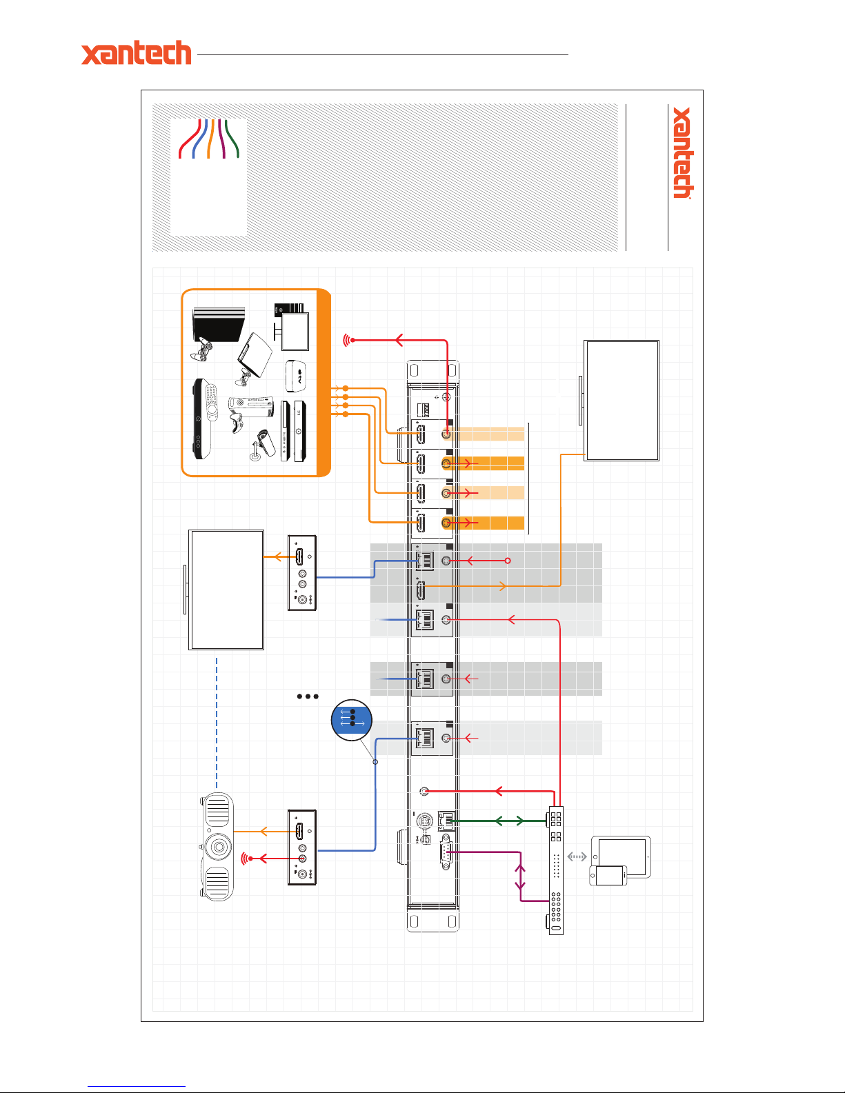
Network Connection
IR Cable
CAT (HDBaseT)
RS-232
HDMI
MAXIMUM OF 4x 4K SOURCES
1 2 3 4
DISPLAY 1
DISPLAY 4
MAX 4x 4K DISPLAYS
LOCAL DISPLAY
Control Processor
70m max
70m max
A B
C
12V POC
A
HDMIBIR
C
SOURCE 01
SOURCE 02
SOURCE 03
SOURCE 04
IR Emitter
Link to source
ZONE
01
ZONE
02
ZONE
03
ZONE
04
Power
HDMI Out
Link
IR IN IR OUT
12V
2A
Power
HDMI Out
Link
IR IN IR OUT
12V
2A
Example Schematic
XT-HDBT-MX44-KIT
Page 11

XT-HDBT-MX44-4K-KIT USER MANUAL
®
© 2018 XANTECH® is a registered trademark of Nortek Security & Control.
Specifications:
XT-HDBT-SP 14-4K
Video Input Connectors: 4x HDMI Type A, 19-pin, female
Video Output Connectors: 1x HDMI Type A, 19-pin, female
4x HDBaseT™ RJ45 connector
RS-232 Serial Port: 1x DB-9, female
EDID: 4-Pin DIP switch
IR Input Ports: 5x 3.5mm stereo jack
IR Output Ports: 4x 3.5mm stereo jack
EDID: 4-Pin DIP switch
Casing Dimensions (W x H x D): 440mm x 201mm x 44mm
Dimensions Inc. Connections (W x H x D): 440mm x 211mm x 52mm
Power Supply : 12V/5A DC
XT-HDBT-EX70-4K-RX
Video Input Connectors: 1x HDBaseT™ RJ45 connector
Video Output Connectors: 1x HDMI Type A, 19-pin female
IR Input ports: 1x 12V 3.5mm stereo jack
IR Output ports: 1x 12V 3.5mm mono jack
Casing Dimensions (W x H x D): 104mm x 27mm x 73mm
Dimensions Inc. Connections (W x H x D): 108mm x 27mm x 73mm
Shipping Weight: 2.7kg
Operating Temperature: 32°F to 104°F (0°C to 40°C)
Storage Temperature : -4°F to 140°F (-20°C to 60°C)
Package Contents:
• 1x X T-HDBT- M X4 4-4K
• 4x XT-HDBT-EX70-4K-RX
• 4x Mounting kit for XT-HDBT-EX70-R X
• 1x 24V/3.5A DC power supply
• 1x Remote control
• 1x Mounting kit
• 1x Quick reference guide
10019309 REV-A0
Page 12

XT-HDBT-MX44-4K-KIT USER MANUAL
www.xantech.com
®
FCC Notice
This equipment has been tested and found to comply with the limits for a Class B digital device, pursuant to part 15 of the FCC Rules. These
limits are designed to provide reasonable protection against harmful interference in a residential installation. This equipment generates, uses, and
can radiate radio frequency energy and, if not installed and used in accordance with the instructions, may cause harmful interference to radio
communications. However, there is no guarantee that interference will not occur in a particular installation. If this equipment does cause harmful
interference to radio or television reception, which can be determined by turning the equipment off and on, the user is encouraged to try to correct
the interference by one or more of the following measures:
• Reorient or relocate the receiving antenna.
• Increase the separation between the equipment and receiver.
• Connect the equipment into an outlet on a circuit different from that to which the receiver is connected.
• Consult the dealer or an experienced radio/TV technician for help.
CAUTION - changes or modifications not expressly approved by the party responsible for compliance could void the user’s authority to operate
the equipment.
CANADA, INDUSTRY CANADA (IC) NOTICES
This Class B digital apparatus complies with Canadian ICES-003.
Operation is subject to the following two conditions: (1) this device may not cause interference, and (2) this device must accept any interference,
including interference that may cause undesired operation of the device.
CORRECT DISPOSAL OF THIS PRODUCT
This marking indicates that this product should not be disposed with other household wastes. To prevent possible harm to the environment or
human health from uncontrolled waste disposal, recycle it responsibly to promote the sustainable reuse of material resources. To return your used
device, please use the return and collection systems or contact the retailer where the product was purchased. They can take this product for
environmentally safe recycling.
Certifications
tech support:
tech@xantech.com
main:
1 (800) 472-5555 - US
1 (707) 283-5900 - International
1 (707) 283-5901 - Fax
web:
www.xantech.com
 Loading...