

Page 1

XT-DL-IRK
DinkyLink™ IR Receiver Kit
Plasma / LCD / LED / CFL Friendly IR Receiver
INSTALLATION INSTRUCTIONS
Page 2

2
DESCRIPTION
These small IR receivers have been designed for mounting in very small spaces.
They may be mounted under shelf edges, cabinet ledges, in wall speakers, etc. –
anywhere an inconspicuous appearance is desired. The high sensitivity of these
receivers allows placement behind speaker grilles and still receive IR commands
up to 80 feet away*.
FEATURES
• Wire channel for clean installation.
• System testing red-talk-back LED.
• Includes 789-44 connecting block, power supply, two 283D, and two 286D
emitters for easy system installation.
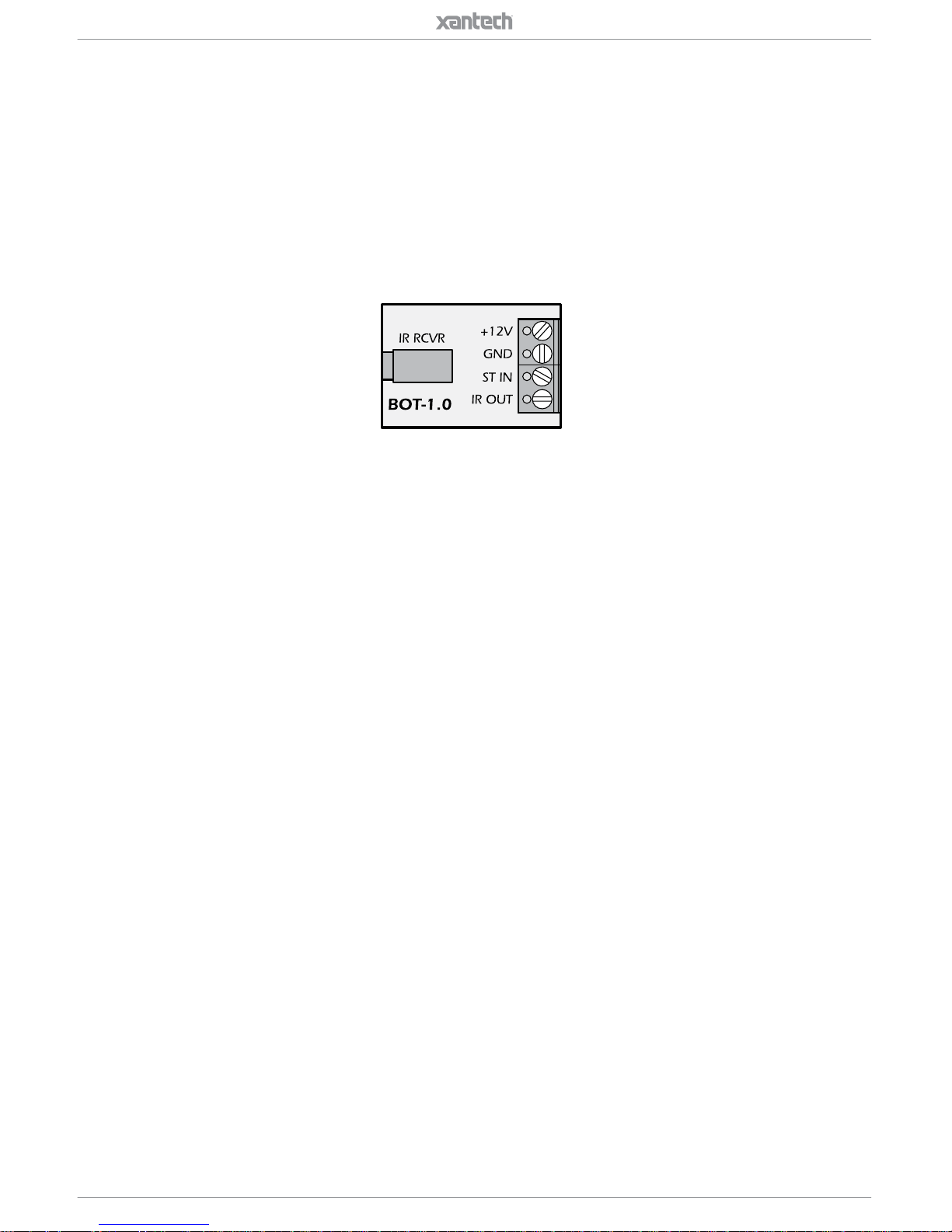
• BOT-1.0 Break Out Terminator
SPECIFICATIONS
• Infrared carrier frequency bandwidth: 25 - 60 kHz.
• Reception range: Up to 80 feet.*
• Reception angle: +/- 60 degrees.
• Cable requirements: See “INSTALLATION” below.
• Max. Transmission length: 1 mile using 18 gauge wire.
• Maximum current output: 100mA.
• Drives IR emitters through Xantech Connecting Blocks, Controllers, etc.
• Dimensions: 2.55” x 0.55” x 0.35” (65mm x 14mm x 9mm).
• Power requirements: +12VDC, 10mA.
*Depending on remote control output strength and ambient conditions.
MOUNTING
The IR receiver can be mounted to any at surface, using the two-sided adhesive
tape supplied.
An additional feature is a wire channel on the rear of the surface mount IR
receiver. This will give the installer the ability to provide clean wire dressing in
any direction.
Page 3
3
INSTALLATION
QUICK-START
A typical system will use an IR receiver, several emitters, and a power supply all
connected to a connecting block.
1. Connect the IR receiver to the “IR RCVR” port on the connecting block.
The ‘red’ connector is installed to the ‘red’ plug. Note: In some extended
distances, additional 3-conductor may be required and can be connected to
the terminals on the connecting block.
2. Connect the Emitters to the connecting block. The ‘yellow’ connector is
installed to the ‘yellow’ plug.
3. Connect the power supply to the connecting block.
PS12-0.5
12VDC
+12 VDC
GND
STATUS
IR IN
EMITTERS
789-44
CONNECTING BLOCK
®
IR
RCVR
Satellite Receiver
283D Emitter
283D Emitter
286D
Emitter
Blu-ray
A/V Receiver
Smart TV Box
DL Series
IR Receiver
Page 4
4
REMOTE ROOM APPLICATION
One application is to locate the IR receiver in a remote room. This will give the
end-user the ability to control audio/video equipment from a location where the
remote control no longer has the ability of direct line-of-sight.
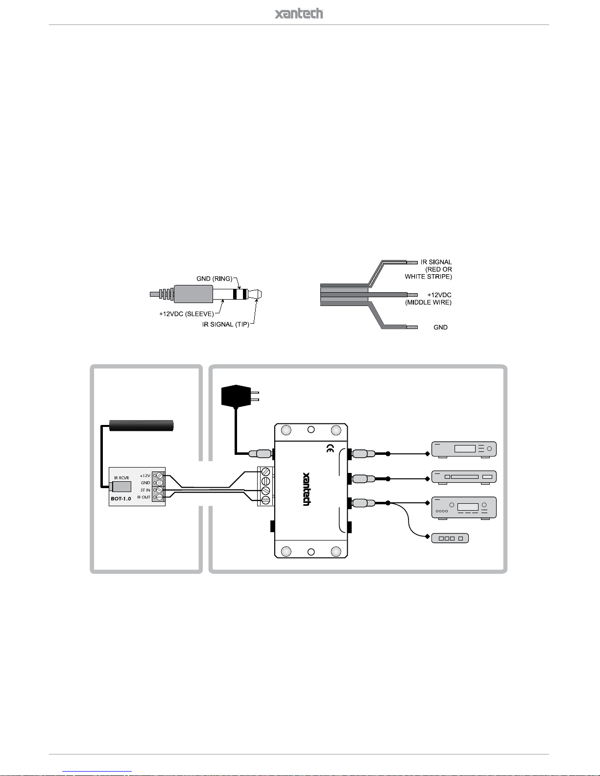
The IR receiver will need the 3.5mm stereo type mini plug removed to extend the
wire run to the connecting block. A 4-terminal block is included to connect the IR
receiver to the connecting block with a 3-conductor inter-room cable in between.
The 3-conductor inter-room cable (24 gauge up to 200’, 22 gauge up to 600’, 20
gauge up to 2000’, 18 gauge up to 5000’), is run to the main room.
Input connections must be made as illustrated. To extend the emitter wires to
DL Series
IR Receiver
Red (or white)
Stripe
To 120 V AC
(unswitched)
781ERGPS
789-44
Connecting Block
REMOTE ROOM
MAIN ROOM
Hand Hel d
Remote
3-Terminal Block (not included)
3-Conductor
Inter-room Cable
(unshielded OK)
7' Ribbon Cable
A/V Receiver
DVD
IR Photodiode
Red
Talk bac k LE D
Satellite Receiver
283D Emitter
12VD C
+12 VDC
GND
STATUS
IR IN
EMITTERS
IR
RCVR
789-44
CONNECTING BLOCK
®
IR OUT
+12V
GND
283D Emitter
283D Emitter
12VDC
+12 VDC
GND
STATUS
IR IN
EMITTERS
789-44
CONNECTING BLOCK
®
IR
RCVR
DL Series
IR Receiver
DL Series
IR Receiver
DL Series
IR Receiver
Remote Room Main Room
789-44
Connecting Block
Satellite Receiver
3-Conductor
Inter-room Cable
(Unshielded OK)
283D Emitter
PS12-0.5
283D Emitter
286D
Emitter
Blu-ray
A/V Receiver
Smart TV Box
a more distant location, you may splice in 2-conductor wire, in the wire gauges
mentioned before, as needed.
While it is possible to make wired connections without the connecting block, it
is not recommended. The connecting block reduces installation time, helps to
eliminate errors, allows easy troubleshooting and permits easy system upgrades
later, if needed.
Page 5
5
BOT-1.0 BREAK-OUT TERMINATOR
Use this unit to interface between the Quad (4-circuit) plug on Xantech Receivers
(so equipped) and 3 or 4-conductor inter-room wiring.
This eliminates the need to cut o the plug and strip and tin the leads for certain
applications.
To 120 V AC
(unswitched)
781ERGPS
789-44
Connecting Block
MAIN ROOM
A/V Receiver
DVD
Satellite Receiver
283D Emitter
12VD C
+12 VDC
GND
STATUS
IR IN
EMITTERS
IR
RCVR
789-44
CONNECTING BLOCK
®
283D Emitter
283D Emitter
Page 6

6
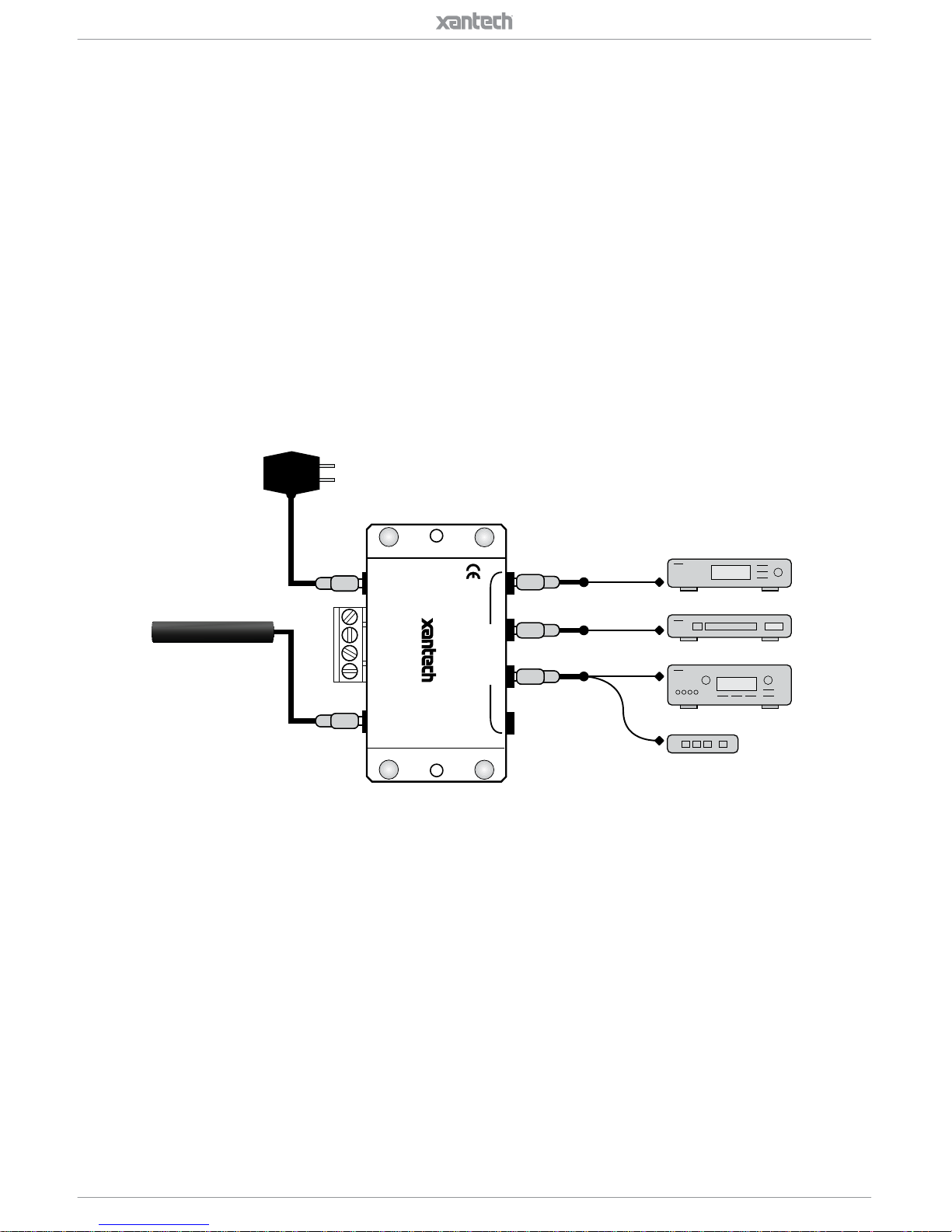
LOCAL SYSTEM APPLICATION
Another application is to locate the IR receiver in a central location, such as
the TV, video screen and/or a speaker. The audio/video equipment can then be
hidden inside a cabinet or located away from the front of a room. This will give
the end user the ability to direct a remote control to one central location and not
have to worry about aiming to the respective device to be controlled.
The IR receiver is in close proximity to the audio/video equipment, no wiring
extension should be required so long as the connecting block is within reach of
the 7-foot cable. The 3.5mm stereo type mini plug is connected to the “IR RCVR”
jack on the Xantech Connecting Block.
PLACEMENT
The IR receiver should be located so that it is not directly facing a light source
such as lamps or displays (standard, LCD, and Plasma). When mounted near a
display, it should be ush to the display and away from light reections that may
occur.
PS12-0.5
12VDC
+12 VDC
GND
STATUS
IR IN
EMITTERS
789-44
CONNECTING BLOCK
®
IR
RCVR
Satellite Receiver
283D Emitter
283D Emitter
286D
Emitter
Blu-ray
A/V Receiver
Smart TV Box
DL Series
IR Receiver
Page 7

7
DINKY-LINK (DL) IR RECEIVER KIT
DESCRIPTION
The DL Series Kit comes with everything needed for a complete IR repeater
system. With a Xantech IR Kit, equipment can now be concealed for clean
room design. In addition, a centralized IR receiver means there is only one IR
target resulting in improved remote control interaction. Featuring color-coded
connectors, a Xantech IR Kit is now an easy to install, and allows a worry-free
installation.
INCLUDED ITEMS
ITEM A: (1) DL Series IR Receiver
ITEM B: (1) 789-44 Connecting Block
Page 8

8
ITEM C:
(2) 283D Single Designer Emitters
ITEM D:
(2) 286D Dual Designer Emitters
STEP 1:
Plug in the 2.1mm Coaxial power plug of the PS12-0.5 Power Supply (ITEM E)
into the jack labeled 12VDC on the 789-44 Connecting Block (ITEM B).
Plug the AC end of the PS12-0.5 Power Supply (ITEM E) into a ‘un-switched’
120V AC Line outlet.
STEP 2:
Connect the 3.5mm stereo mini plug from the DL IR Receiver (ITEM A) to the ‘IR
RCVR’ input located on the 789-44 Connecting Block (ITEM B).
The RED connector connects to the RED receptacle.
ITEM E:
(1) PS12-0.5
Power Supply
ITEM F:
(1) BOT-1.0
Break Out Terminator
Page 9

9
STEP 3:
Plug in the 283D/286D Designer Emitters 3.5mm mono mini plugs (ITEM C/D)
into the jacks labeled EMITTERS on the 789-44 (ITEM B) and aix the opposite
end to the IR Sensor Window of the controlled equipment. Extra double sided
adhesive tape is included.
The YELLOW connector connects to the YELLOW receptacle.
PS12-0.5
Remote
12VDC
+12 VDC
GND
STATUS
IR IN
EMITTERS
789-44
CONNECTING BLOCK
®
IR
RCVR
Satellite Receiver
283D Emitter
283D Emitter
286D
Emitter
286D
Emitter
Blu-ray
A/V Receiver
Smart TV Box
DL Series
IR Receiver
Display 1 Display 2
Page 10

10
IR TROUBLESHOOTING GUIDE
NOTE: Due to the many variables in a given installation, the troubleshooting
countermeasures you will have to take may vary from job to job. Each
installation is dierent due to the number of IR receivers in use, length of
wire runs, type of wire, amount of ambient IR noise present, etc…. Therefore,
your countermeasures for a particular job will range from nothing at all, to any
combination of the solutions listed below.
IR Receivers: Model #’s DL, HL, ML, and WL series
Cause Solution
1. Weak Batteries in Transmitting
Remote.
Replace batteries.
2. Bad Emitter or no emitter plugged
into connecting block.
Test emitter and verify wiring.
3. Signal wire between IR Receiver
and the Connecting Block is
open.
Recheck wiring.
4. Power Supply not putting out
proper voltage.
Verify supply is a 12VDC regu-
lated supply reading between 11.5
to 13VDC under load. Should be
using Power Supply Model PS12-0.5
(12VDC Regulated, 200mA) or PS12-
1.25 (12VDC Regulated, 1.2A)
5. Output from the IR receiver/
connecting block is connected to
a high impedance IR input jack on
a component.
If you are using a passive connecting
block, such as a 789-44, and the sys-
tem is not working, try the amplied
connecting block, model 791-44. Put
one of the small plastic case jumpers
supplied with the block on the pins
next to the emitter jack. This will pro-
vide the IR-in jack on the component
with a hotter signal.
6. IR Receiver is inoperable. Replace Receiver.
7. (XTRALINK Only) RF Amplier is
being used on same COAX Line
anywhere between the Coupler
(CPL94) and Injector (INJ94).
Need to use a Bypass Kit (model
BYPASS94 Kit) to route the IR control
signals around the amplier(s).
Symptom #1:
DIM or NO Talk Back LED during IR Reception or reduced operational range
Page 11

11
Symptom #2:
TB LED on IR Receiver (and/or Emitters) Dimly lit or ickering
Cause Solution
1. Signal and ground wires are
reversed or shorted either at the
connecting block or IR receiver.
Recheck your wiring.
2. Defective emitter. Replace Emitter
3. Relatively high levels of ambient
noise. This can be due to any of
the following: Sunlight, orescent
Lighting or Plasma Displays.
In this case use either a SUN lter
(SUNKIT), or any of our ‘Plasma/
CFL Friendly’ IR Receivers (DL85/95,
HL85/95, ML85/95, WL85/95). These
can also be used in direct sunlight
and in the presence of ‘tube style’
uorescent lighting.
4. EMI induced noise. This can be
due to light dimmer controls or
other radiating electronic devices
(PC’s or any poorly shielded
electronic device).
Reposition IR Receiver and/or cabling
away from emitting device. You can
also place a 470Ohm resistor in
parallel with the IR Signal and GND
connections on the connecting block.
This will also help alleviate any stray
capacitance in the cable.
5. Plasma Interference Use an 85 or 95 series Plasma
'Friendly' IR Receiver. If already us-
ing a 85 or 95 unit, please note the
Plasma interference can be reected
o of any item it comes into contact
with within approx. 3ft. From the front
of the display. Keeping this in mind,
make sure that the IR receiver is free
from any obstruction that might reect
back into the receiving eye.
Page 12

12
Symptom #3:
TB LED on IR Receiver (and/or Emitters) on solid
Cause Solution
1. Plasma Interference Use a 85 or 95 series Plasma
'Friendly' Receiver. If already using a
this unit, please note the Plasma in-
terference can be reected o of any
item it comes into contact with within
approx. 3ft. From the front of the dis-
play. Keeping this in mind, make sure
that the IR receiver is free from any
obstruction that might reect back into
the receiving eye.
2. Voltage and Ground wires are
reversed at the connecting block
or IR Receiver
Recheck your wiring.
3. Relatively high levels of ambient
noise. This can be due to any of
the following: Sunlight, orescent
Lighting or Plasma Displays.
In this case use either a SUN lter
(SUNKIT), or any of our ‘Plasma/
CFL Friendly’ IR Receivers (DL85/95,
HL85/95, ML85/95, WL85/95). These
can also be used in direct sunlight
and in the presence of ‘tube style’
uorescent lighting.
4. EMI induced noise. This can be
due to light dimmer controls or
other radiating electronic devices
(PC’s or any poorly shielded
electronic device).
Reposition IR Receiver and/or cabling
away from emitting device. You can
also place a 470Ohm resistor in
parallel with the IR Signal and GND
connections on the connecting block.
This will also help alleviate any stray
capacitance in the cable.
5. Power Supply not putting out
proper voltage.
Verify supply is a 12VDC regu-
lated supply reading between 11.5 to
13VDC under load.
Page 13

13
Symptom #4:
TB LED on IR Rec. blinks but 283D or 286D ‘Blink’ style Emitters do not
Symptom #5:
Intermittent IR control (I.e. buttons on remote need to be pressed multiple times)
Cause Solution
1. There may be a short, such as a
staple driven through the Signal
and GND wires of the IR Receiver
and/or the emitter.
Recheck your wiring.
2. Emitter may be shorted internally Replace Emitter or use TEST EMIT-
TER to check circuit.
3 (XTRALINK Only) TV on same
splitter with no IR Receiver
installed
Place a DC Blocker (Model 203-00) on
any TV Leg without IR Receiver
Cause Solution
1. Plasma Interference Use a 85 or 95 series Plasma 'Friendly' Receiver
2. Relatively high
levels of ambient
noise. This can be
due to any of the
following: Sunlight,
orescent Lighting
or Plasma Displays.
In this case use either a SUN lter (SUNKIT), or
any of our ‘Plasma/CFL Friendly’ IR Receivers
(DL85/95, HL85/95, ML85/95, WL85/95). These
can also be used in direct sunlight and in the
presence of ‘tube style’ uorescent lighting.
3. Long Wire Runs
– shielded wire typi-
cally of 100 feet (30
meters) or longer
causes a lter eect
due to accumulated
capacitance of the
wire. Intermittent,
or no IR control,
could actually be
because of the
longer wire runs.
Putting a 470-ohm resistor in parallel at the
connecting block between signal and ground
will eectively discharge the capacitance of the
wire. This will allow the signal to travel farther on
shielded wire. Adding a resistor between the
input and ground of the connecting block will drop
the IR level down somewhat. Passive connect-
ing blocks, such as the 789-44, may not have
enough signal output for consistent control of the
equipment. You may have to upgrade to an am-
plied connecting block to bring the IR level back
to normal. In these cases, the 791-44 would be
an ideal connecting block for single zone systems
while the 795-20 would work best for a 2-4 zone
system.
Page 14

14
Symptom #6:
Emitters function but some (or all) components do not respond.
Cause Solution
1. Emitter placement is incorrect. Reposition the Emitter so that it is
directly over the components sensor
window. Consult the components
owners’ manual of the unit for the
exact location of the IR Sensor
Window.
2. Emitter placement is correct but
the signal is overpowering the
unit or there is bleed-through
from other emitters close by.
Reposition the Emitter to a position
that is suitable for the unit. Use a
283 or 286D Blink style emitter (they
have a lower output than non-blink
emitters 282 and 284M). If the com-
ponents do not need to be controlled
directly without an IR Repeater
system (components are located in
an equipment closet), place a Mouse
Emitter Shield cover over the Emitter
(PN#MS1). The rounded (non-stick)
side of the emitter is a hi-output side
and can reect o other devices and
overpower some components IR
Sensors. If using a CB12 connect-
ing block, try a 789-44 connecting
block. This has a series resistor at
the output, which will limit current to
the Emitter.
Page 15

15
Symptom #7:
Absolutely No Functionality (How to determine which component is at fault)
Component to
Test
Instructions
1. Verify Power Supply With a Multimeter, measure the DC Voltage of
the supply while it is connected to the Connecting
Block. Put the Negative lead of the meter on the
terminal marked GND and the Positive Lead on
the terminal marked 12VDC (or V). You should
get a reading between 11.5VDC and 13.0VDC.
If not, remove the supply from the Connect-
ing block and measure again this time directly
on the 2.5mm Coaxial plug. If it reads between
11.5VDC and 13VDC, power supply is most likely
good. Reconnect to the Connecting Block and
proceed to step 2. NOTE: In most cases this will
indicate the supply is good but in some cases the
supply can still be bad (i.e. reads good when not
plugged in but may not be able to handle the cur-
rent load of the system.)
2. Verify Emitter.
(283D or 286D
Blink Style ONLY)
Remove the power supply from the connecting
block and all Emitters from the output. Place a
jumper wire on the connecting block between IR
and +12v. Reconnect the Power Supply and one
emitter. The Emitter should Light bright and solid.
Repeat for all emitters.
3. Verify Emitter.
(282M or 284M
NON Blink Style)
Use a diode tester to verify proper Emitter opera-
tion. Remove Emitter from Connecting Block.
Place the Positive Lead of the tester on the TIP of
the Mono Mini Plug and the Negative Lead on the
Shield of the Mono Mini Plug. Meter should read
a voltage. When the leads are reversed (Positive
lead on Shield and Negative lead on TIP) you
should not get any voltage reading at all.
4. Verify IR Receiver. Remove the power supply from the connecting
block and all Emitters from the output. Place a
jumper wire on the connecting block between IR
Signal and GND. Reconnect the Power Supply.
With a known good hand-held remote, shoot a
constant IR Command at the receiver and verify
the TB LED on the Receiver lights.
Page 16

LIMITED WARRANTY
Xantech® warrants its products to be free of defects in materials or workmanship.
This is a Limited Lifetime warranty from the date of purchase by the original
consumer. Any products returned to Xantech and found to be defective by
Xantech within the warranty period will be repaired or replaced, at Xantech’s
option, at no charge. Xantech will not be responsible for the actual cost of
installation or removal of the product, nor for any incidental or consequential
damages. Some states do not allow the exclusion or limitation of incidental or
consequential damages, so the above limitation may not apply to you.
This warranty gives you specic legal rights. You may have additional legal rights
that vary from state to state.
www.xantech.com
1800 S McDowell Blvd. Petaluma CA 94954 USA
800.472.5555 or 707.283.5900
©2017 Core Brands, LLC. All rights reserved.
Xantech® is a registered trademark of Core Brands, LLC. All trademarks are the property of their
respective owners. All features, specications, hardware, packaging, and documentation are subject to
change without notice.
P/N: 10018830 Rev-A0 - 08/2017
 Loading...