

Page 1

INSTALLATION INSTRUCTIONS
Ceiling and In-Wall Speaker Systems
INTRODUCTION
The XTC and XTC Reference series loudspeakers are the result of Xantech’s commitment to build
the best speakers possible. In their quest for perfection, Xantech engineers examined every aspect of
their performance and design, from electronic components to structural material, even how they
interact with the home environment. The Result: Flawless performance that you never thought
possible from an installed speaker.
• Pivoting Tweeters
Pivoting dome tweeters provide brilliant highs, and allow the sound field to be adjusted to fit the
specifics of the listening environment. In-wall speakers can accept a Dinky Link™ IR receiver for a
convenient, discreet mounting solution. In-ceiling speakers have an aerodynamic dome-shaped
tweeter housing that eliminates woofer sound-wave restriction.
• FIM
FIM (Flexible Impedance Matching) binding posts provide a more dependable solution for adding a
second pair of speakers to a room or zone. One post is set for 6 ohms, delivering maximum SPL.
Another flexible post provides 8 ohms for attaching two speaker pairs in parallel without harming the
amplifier.
• XTC Technology
Xantech XTC technology delivers amazing sound quality. Custom-designed crossovers deliver a
pure, smooth tonal range that goes beyond the typical expectations of an installed speaker.
• High-density MDF Baffles
The In-Wall baffles are constructed with the same high-density MDF wood material found in premium
box speakers. An MDF based speaker provides sonic clarity by reducing vibrations and resonance.
The XTC baffle design increases dynamics, provides solid bass and midrange performance.
• SoundPATH Bridge Design
The XTC Reference In-Ceiling baffles are designed to eliminate the adverse-effects of having the
tweeter placed directly over the woofer. SoundPATH’s solid-density bridge design provides sonic
clarity by reducing vibrations and resonance. An aerodynamic shape eliminates woofer sound-wave
restriction.
• XA and XB Series
The XTC series is also known by the model numbers as the XB series. The XTC Reference series is
also known by the model numbers as the XA series.
08905092C - 1 -
Page 2
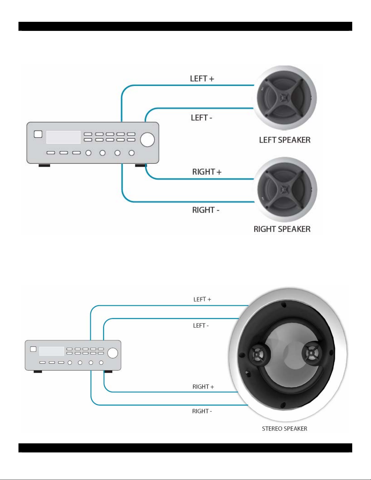
APPLICATION – SINGLE ZONE
A single zone setup can be created using an audio receiver, general purpose amplifier, or a multiroom amplifier. The figure below shows a typical stereo left and right speaker setup.
APPLICATION – SMALL AREA (BATHROOM, LAUNDRY ROOM)
Small areas such as bathrooms and laundry rooms may not have enough room for a pair of left and
right speakers. The XA65CS and XB65CS are perfect for this type of situation. The “CS” ceiling
stereo speakers are designed with stereo left and right audio in one single installed package. The
figure below shows a typical installation.
08905092C - 2 -
Page 3
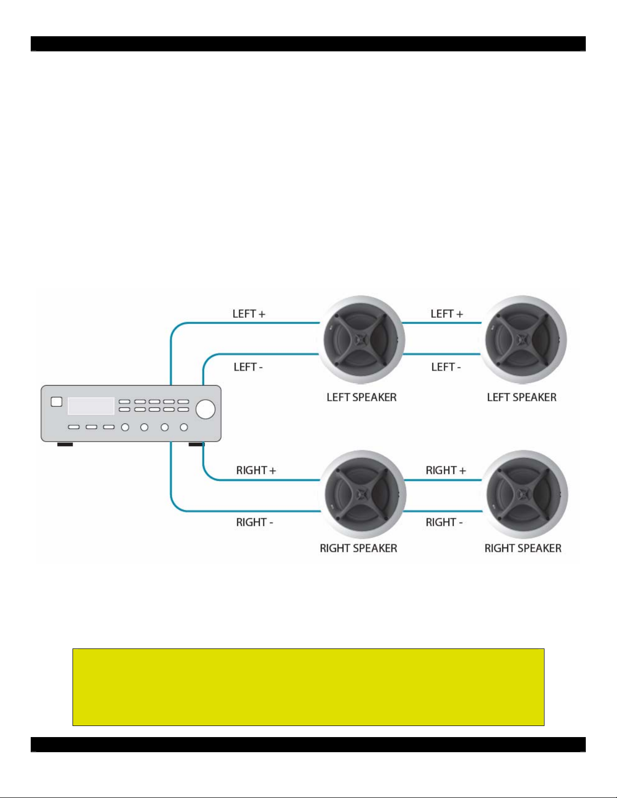
ADVANCED APPLICATION – LARGE AREA, MULTIPLE SPEAKER SYSTEMS
Large areas such as gathering rooms or banquet halls may require more than a single pair of
speakers. Multiple speakers can be connected to the same amplifier channel. This application
requires careful understanding of the amplifiers capabilities.
1) Determine what the minimum speaker impedance the amplifier can handle. This should be
noted on the amplifier or the amplifier’s instruction manual. Typically, most amplifiers can had
a minimum of 4-ohms per speaker channel.
2) The XA and XB series speakers are 6-ohms. By connecting two 6-ohm speakers to one
amplifier channel, a 3-ohm speaker load is created. For amplifiers with a 4-ohm minimum, this
is an improper application that can cause damage to the amplifier.
3) The XA and XB series speakers provide a third wiring post for this type of application. Remove
the yellow plastic cap to expose the “+8” wiring post. Using the “+8” wiring post will make the
XA and XB series speaker 8-ohms. By connecting two 8-ohm speakers to one amplifier
channel, a 4-ohm speaker load is created. For amplifiers with a 4-ohm minimum, this is an
acceptable application.
The figure above shows multiple speakers connected to a single output amplifier channel by using
FIM (flexible impedance matching). To make sure the impedance matches the amplifiers minimum 4ohm specification, the “+8” post is used. The yellow cap that was once on the “+8” post is moved to
the “+6” post as an added precaution.
Note: A 6-Ohm load is the optimum load for a single speaker per
channel. The best sound is a result of a single 6-Ohm connection.
Be sure to verify the amplifiers minimum impedance capability.
08905092C - 3 -
Page 4
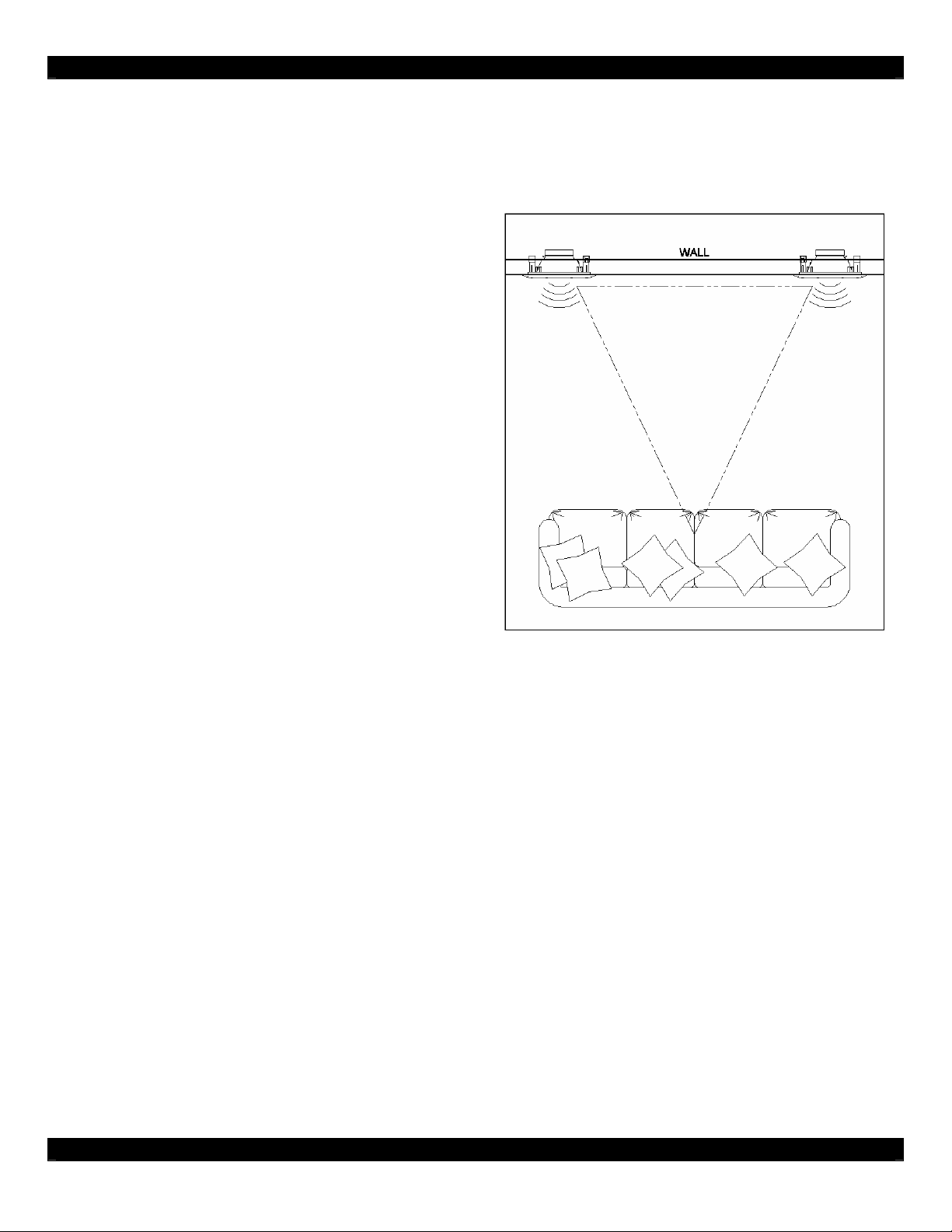
REQUIREMENTS – SPEAKER PLACEMENT
The best sound can be achieved by making sure the speakers are placed is the best position
possible. The surface material should be similar for right and left pairs. Also, the cavity volume behind
each speaker should be identical.
Placing a speaker near a corner tends to emphasize
bass. Large surface areas emphasize treble.
Drapes and upholstered furniture may muffle sound.
Be sure that both right and left pairs are equal
distance from the corners of a room and facing
identical surfaces. Non-equality between the left and
right speakers may result in inconsistent sound.
The objective of a well designed speaker system is
how well it replicates live sound. A speaker system
that can present a 3-dimensional replication as if the
performer is in front of the listener presents “stereo
imaging”.
The left and right channels of a speaker system are
best placed 6 to 8 feet apart. The best height for the
in-wall systems is where a person standing and a
person sitting are within the optimum range of the
tweeter. In general, the optimum height should be
4.5 feet from floor to tweeter. This height covers
both standing and sitting.
REQUIREMENTS – WIRE
For the best installation, using high-quality speaker wire is recommended. High-quality speaker wire
is stranded. Do not use solid gauge wire (commonly used for 120VAC and 240VAC power
connections).
Wire Length Recommended Size
Up to 50 feet 16-gauge
Up to 100 feet 14-gauge
Greater than 100 feet 12-gauge
The general rule is that a heavier gauge wire is recommended for all installations, especially for long
distances. Be sure to select a wire that has an easy to follow indicator (such as a white stripe or
indented ridge). This will make connecting the polarity correctly an easier task.
Be sure to observe the proper polarity. The positive (+) wire must always be connected to the positive
(+) terminal and the negative (-) wire must always be connected to the negative terminal. An incorrect
polarity connection will result in poor imagining and bass response.
Note: Be sure that each wire strand is completely isolated from other connections. Frayed or poorly
twisted strands may cause short circuits and damage the systems equipment.
08905092C - 4 -
Page 5

CAUTION: In-Ceiling Installation
Be sure that the ceiling material has a good integrity and is of a
material and thickness to support the weight and vibrations of the
speaker installation.
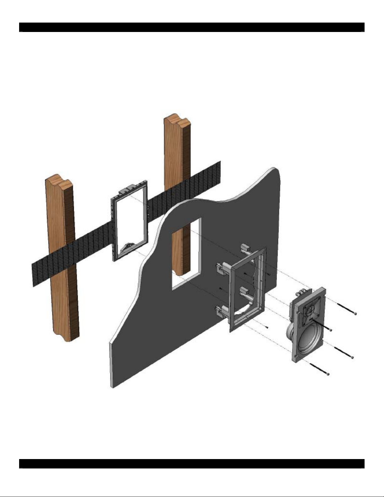
NEW CONSTRUCTION INSTALLATION
The preferred method for new construction installation is using Xantech’s new-construction brackets.
The brackets provide an installation process that protects the high-value speaker system. The bracket
material is heavy-duty ABS plastic. Wings can be assembled to the frame in several locations, thus
allowing the speaker system to be installed in almost any position.
1) The speaker bracket installation takes place after wiring and wall box placement has been
completed. The speaker brackets are to be installed before the dry-wall process. The dry-wall
contractors can accurately cut out the speaker holes using the installed speaker brackets as a
reference.
2) After the dry-wall process is complete, the painting process is next. The bezel frame from the
speaker system can be installed using the speaker bracket as a mounting point. There are two
mounting points to fasten the bezel frame to the bracket. Remove the bezel from the speaker
frame by locating and removing the shipping screws (silver) on the rear of the system. The
dog-ears screws also have to be removed. With the bezel frame installed into the speaker
bracket, paint can now be applied to the wall and speaker bezel.
08905092C - 5 -
Page 6
3) The baffle part of the speaker system can now be installed into the speaker bezel. Place the
baffle into the bezel frame. Use the dog-ears on the speaker bezel to secure the system into
place.
4) Installation complete! The benefit of using the new construction speaker brackets is that you
can maintain possession of the high-value portion of the speaker system instead of passing it
through several different contractors.
08905092C - 6 -
Page 7

EXISTING CONSTRUCTION INSTALLATION
1) Determine the location for the installed speaker. Use a stud-finder to locate the studs behind
the wall. It is a good idea to use a voltage detector to determine if any live wiring is in the area.
Typically an electrical or switch outlet will identify the location of a stud. The adjacent stud may
be 12, 16 or 24 inches apart.
2) Using the included mounting template, draw an outline of the area that will be removed. The
outline should at least 2 to 3 inches away from a stud. This will allow the proper clearance for
the dog-ears. For applications where the speaker frame must be against a stud, the speaker
frame has an area on each leg where direct-to-stud mounting can be applied. It is a good idea
to use level to be sure the rectangular outline is level. Drill a small pilot hole to allow probe
entry.
3) Use a stiff wire to probe inside the wall. Use this probe to check for obstruction such as pipes.
The probe can also be used to verify the depth is adequate for the installed speaker.
4) Use a dry-wall saw or a jig-saw to slowing remove the outlined area. Place the speaker in the
cavity to verify the fit and level is correct. It is recommended to loosely fill the cavity with firerated fiberglass insulation. This will prevent unwanted sound to adjacent rooms. Filling the
cavity also enhances the performance of the speaker system.
08905092C - 7 -
Page 8

5) Connect the speaker wires to the speaker and place the speaker inside the wall cavity.
6) Carefully tighten the clamping screws. Be sure to alternate diagonally between each screw
position. For wall speakers, carefully adjust the frame level after each screw is installed.
CAUTION: DO NOT OVER-TIGHTEN THE SCREWS!
This may cause damage to the wall and speaker system.
7) INSTALLATION COMPLETE!
08905092C - 8 -
Page 9

FINISHING TOUCH – PIVOTABLE TWEETER
All speaker models, except the stereo ceiling models, have pivot-able tweeters. As mentioned in the
speaker placement section, the tweeter should be level to the listener’s ear.
Adequate Tweeter Direction
Optimum Tweeter Direction
Gently push the edge of the tweeter frame to adjust the angle. Be careful not to touch the dome
portion of the tweeter. The tweeter must be treated with care to maintain it’s high performance
characteristics.
FINISHING TOUCH – TWEETER & EQUALIZATION SWITCH
All XA series speakers are designed with a 3-position equalization switch. The center position is
nominal (normal position). Moving the speaker switch towards the “+” will increase the equalization
response. Moving the speaker switch towards the “-“ will decrease the equalization response. The
equalization will affect the treble and bass.
All XB series speakers are designed with a 3-postion tweeter switch. The center position is nominal
(normal position). Moving the speaker switch towards the “+” will increase the tweeter response.
Moving the speaker switch towards the “-“ will decrease the tweeter response. The tweeter will affect
the treble only.
FINISHING TOUCH – PAINTING
The frame and grill can be painted to match the wall or ceiling color. Included is a paint shield that is
meant to replace the grill on the speaker assembly. This will protect the speaker while exposing only
the frame.
The grill should not be painted while assembled to the speaker assembly. It is suggested to use spray
paint on the grill. Be sure the perforations (holes) in the grill do not fill with paint. Several light coats
will yield the best results.
08905092C - 9 -
Page 10

TROUBLESHOOTING
1. POLARITY
It is a good idea to test the polarity of the speaker and wire connection. Testing the polarity confirms
that positive (+) wire is connected to the positive (+) terminal on the speaker and amplifier. A reversepolarity connection (positive (+) wire connected to negative (-) terminal) will result in poor speaker
performance and possibly damage the system.
To test the polarity, take a 9 Volt battery. Connect the negative (-) terminal of the 9 Volt battery to the
negative (-) wire. Then, while observing the woofer on a speaker, connect the positive (+) terminal of
the 9 Volt battery to the positive (+) wire.
If the woofer on the speaker moves outwards, the wiring polarity is correct. If the woofer on the
speaker moves inward, the wiring polarity is incorrect. In this situation, it is best to correct the polarity
by swapping the positive (+) and negative (-) wire on back of the speaker.
2. CHANNEL CHECK
To check that the left speaker is not connected as a right speaker, you will need an amplifier or
preamplifier that has BALANCE control. Turn on the system so that music is coming from the speaker
system. Move the BALANCE control to the far right. The right speaker should only be producing
sound. Move the BALANCE control to the far left. The left speaker should only be producing sound.
If the above case is not true, then it would be easiest to correct the problem at the equipment rack.
The problem may not be at the amplifier to speaker connection. It is a good idea to check source to
amplifier connection as well.
3. NO SOUND FROM SPEAKER
In the event that no sound from the speaker is heard, check the wiring or the items below.
A. Verify the correct source is playing and is selected on the receiver\amplifier end.
B. Verify mute and volume levels are correct. Verify volume control is wired properly.
C. Some receivers have A or B selector switches, verify the correct output is switched. This also
applies to speaker selector switches and advanced volume controls.
D. A wire short-circuit may cause the amplifier to shut-down in protection mode.
E. Bad connecting between the source and receiver\amplifier end.
SPECIFICATIONS - OVERVIEW
XTC SERIES
Tweeter: Pivotable Teteron dome tweeter constructed with
advance neodymium magnet, fluid cooled, and rear
acoustic damping.
Woofer: Durable IMG (injection molded graphite) woofer
for higher sensitivity and increased sound pressure levels.
Crossover: Second-order network. (12dB per octave).
Premium components specified and designed into the
system.
XTC REFERENCE SERIES
Tweeter: Pivotable Titanium dome tweeter. Rear acoustic
damping and positive rubber surround removes ringing and
achieves pure tones with low distortion.
Woofer: Premium Al/Mg (aluminum magnesium material)
woofer stays rigid during the most extreme bass notes and
the agility results in accuracy and dynamic bass response.
Crossover: Third-order network. (18dB per octave). Premium
components specified and designed into the system.
08905092C - 10 -
Page 11
SPECIFICATIONS
XB525C
Speaker Type: Ceiling Mount
Driver size: 5.25” Woofer / 22mm Tweeter
Recommend Amplifier Power: 5-60 Watts
Frequency Response: 50Hz-22kHz
Impedance: 6 or 8 ohm selectable
Sensitivity (1Watt/1Meter): 90dB
Overall Dimensions: 7.96" DIA. x 5.25” Depth
Cut-Out Size: 6.75” DIA.
Construction Bracket Available: XBKT525C
(sold separately)
XB65C
Speaker Type: Ceiling Mount
Driver size: 6.5” Woofer / 22mm Tweeter
Recommend Amplifier Power: 5-80 Watts
Frequency Response: 42Hz-22kHz
Impedance: 6 or 8 ohm selectable
Sensitivity (1Watt/1Meter): 90dB
Overall Dimensions: 9.24" DIA. x 5.50” Depth
Cut-Out Size: 8.05” DIA.
Construction Bracket Available: XBKT650C
(sold separately)
XB8C
Speaker Type: Ceiling Mount
Driver size: 8” Woofer / 28mm Tweeter
Recommend Amplifier Power: 10-100 Watts
Frequency Response: 35Hz-20kHz
Impedance: 6 or 8 ohm selectable
Sensitivity (1Watt/1Meter): 90dB
Overall Dimensions: 10.92" DIA. x 6.00” Depth
Cut-Out Size: 9.72” DIA.
Construction Bracket Available: XBKT800W
(sold separately)
XB65CS
Speaker Type: Ceiling Mount
Driver size: 6.5” Dual Coil Woofer / Twin 22mm Tweeters
Recommend Amplifier Power: 5-70 Watts
Frequency Response: 42Hz-22kHz
Impedance: 6 or 8 ohm selectable
Sensitivity (1Watt/1Meter): 90dB
Overall Dimensions: 9.24” DIA. x 6.00” Depth
Cut-Out Size: 8.05” DIA.
Construction Bracket Available: XBKT650C
(sold separately)
XB525W
Speaker Type: Wall Mount
Driver size: 5.25” Woofer / 22mm Tweeter
Recommend Amplifier Power: 5-60 Watts
Frequency Response: 50Hz-22kHz
Impedance: 6 or 8 ohm selectable
Sensitivity (1Watt/1Meter): 90dB
Overall Dimensions: 11.45” W x 7.30 H x 3.75” Depth
Cut-Out Size: 10.23” W x 6.08” H
Construction Bracket Available: XBKT525W
(sold separately)
XB65W
Speaker Type: Wall Mount
Driver size: 6.5” Woofer / 22mm Tweeter
Recommend Amplifier Power: 5-80 Watts
Frequency Response: 42Hz-22kHz
Impedance: 6 or 8 ohm selectable
Sensitivity (1Watt/1Meter): 90dB
Overall Dimensions: 13.46” W x 8.24” H x 3.75” Depth
Cut-Out Size: 12.24” W x 7.02” H
Construction Bracket Available: XBKT650W
(sold separately)
XB8W
Speaker Type: Wall Mount
Driver size: 8” Woofer / 28mm Tweeter
Recommend Amplifier Power: 10-100 Watts
Frequency Response: 35Hz-20kHz
Impedance: 6 or 8 ohm selectable
Sensitivity (1Watt/1Meter): 90dB
Overall Dimensions: 16.37” W x 9.80” H x 4.00” Depth
Cut-Out Size: 15.15” W x 8.58” H
Construction Bracket Available: XBKT800W
(sold separately)
08905092C - 11 -
Page 12
SPECIFICATIONS
XA65C
Speaker Type: Ceiling Mount
Driver size: 6.5” Woofer / 22mm Tweeter
Recommend Amplifier Power: 10-85 Watts
Frequency Response: 40Hz-30kHz
Impedance: 6 or 8 ohm selectable
Sensitivity (1Watt/1Meter): 90dB
Overall Dimensions: 9.24" DIA. x 5.50” Depth
Cut-Out Size: 8.05” DIA.
Construction Bracket Available: XBKT650C
(sold separately)
XA8C
Speaker Type: Ceiling Mount
Driver size: 8” Woofer / 26mm Tweeter
Recommend Amplifier Power: 10-110 Watts
Frequency Response: 32Hz-24kHz
Impedance: 6 or 8 ohm selectable
Overall Dimensions: 10.92" DIA. x 6.00” Depth
Cut-Out Size: 9.72” DIA.
Sensitivity (1Watt/1Meter): 90dB
Construction Bracket Available: XBKT800C
(sold separately)
XA65CS
Speaker Type: Ceiling Mount
Driver size: 6.5” Dual Coil Woofer / Twin 22mm Tweeters
Recommend Amplifier Power: 10-80 Watts
Frequency Response: 40Hz-30kHz
Impedance: 6 or 8 ohm selectable
Sensitivity (1Watt/1Meter): 90dB
Overall Dimensions: 9.24” DIA. x 6.50” Depth
Cut-Out Size: 8.05” DIA.
Construction Bracket Available: XBKT650C
(sold separately)
XA65W
Speaker Type: Wall Mount
Driver size: 6.5” Woofer / 22mm Tweeter
Recommend Amplifier Power: 10-85 Watts
Frequency Response: 40Hz-30kHz
Impedance: 6 or 8 ohm selectable
Sensitivity (1Watt/1Meter): 90dB
Overall Dimensions: 13.46” W x 8.24” H x 3.75” Depth
Cut-Out Size: 12.24” W x 7.02” H
Construction Bracket Available: XBKT650W
(sold separately)
XA8W
Speaker Type: Wall Mount
Driver size: 8” Woofer / 26mm Tweeter
Recommend Amplifier Power: 10-110 Watts
Frequency Response: 32Hz-24kHz
Impedance: 6 or 8 ohm selectable
Sensitivity (1Watt/1Meter): 90dB
Overall Dimensions: 16.37” W x 9.80” H x 4.00” Depth
Cut-Out Size: 15.15” W x 8.58” H
Construction Bracket Available: XBKT800W
(sold separately)
Xantech Corporation
13100 Telfair Avenue, 2/F
Sylmar, CA 91342
Phone: (818) 362-0353, Fax: (818) 362-9506
Instructions, Speakers © 2007 Xantech Corporation
This document is copyright protected. No part of this manual may be
copied or reproduced in any form without prior written consent from
Xantech Corporation.
Xantech Corporation shall not be liable for operational, technical, or
editorial errors/omissions made in this document.
08905092C - 12 -
 Loading...