

Page 1

HDMI4X4
User Manual
www.xantech.com
- 1 -
Page 2
INTRODUCTION
Thank you for purchasing the 4x4 HDMI Matrix.
The 4x4 HDMI Matrix switches four HDTV sources to any four HDMI displays.
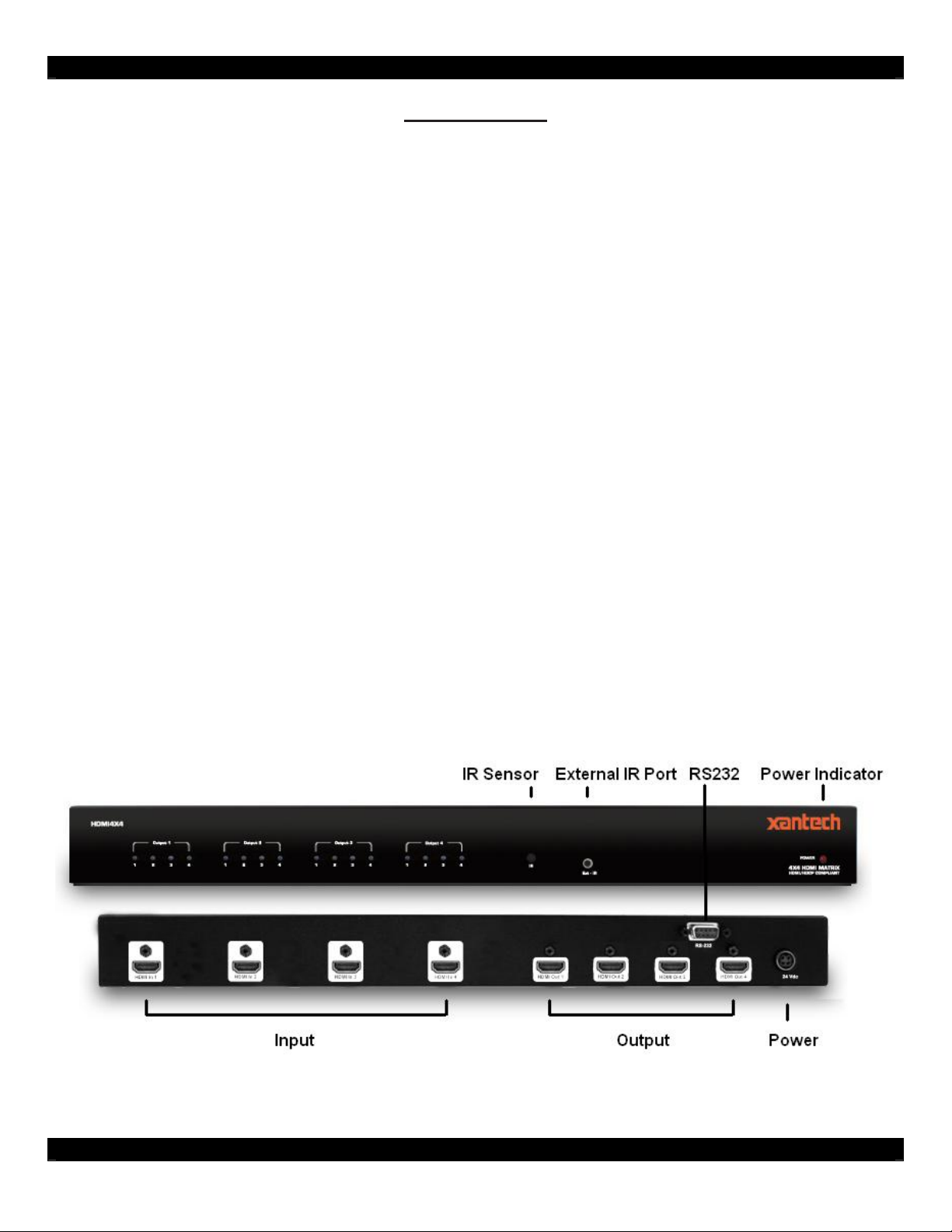
The 4x4 HDMI Matrix switcher has four HDMI inputs and four HDMI outputs. Matrix input
#1 and the HDMI port of HDTV source #1 connects using a male to male HDMI cable. The
HDMI port of HDTV source #2 connects to HDMI input #2. The HDMI port of HDTV source
#3 connects to HDMI input #3. The HDMI port of HDTV source #4 connects to HDMI input
#4. There are four (4) HDMI outputs connecting to four (4) different displays.
Note: The switching is done by using either the RMT-16-IR remote control or through the RS232 port.
The 4x4 HDMI Matrix is rack mountable. Any HDTV with DVI inputs can be connected to the HDMI
outputs of the matrix by using a DVI to HDMI adapter if the cable used is DVI.
• Allows any HDMI display to view any source at any time
• Allows any source to be displayed on multiple displays at the same time
• Maintains resolutions up to 1080p, 2k, and 1920x1200
• Maintains highest HDMI single link video resolution
• Maintains highest HDMI digital audio signal
• Supports HDCP compliant devices
• HDMI or DVI to HDMI cables are used to connect the inputs and the matrix output
• Each display's inputs can be switched with the IR remote control or through RS232
The HDMI4X4 consists of:
(1) 4x4 HDMI Matrix
(4) HDMI 6 Cables (M-M)
(1) 24VDC Power Supply
(1) User Manual
(1) RMT-16IR Remote Control
(1) Rack Ears
- 2 -
Page 3

OPERATION NOTES
READ THESE NOTES BEFORE INSTALLING OR OPERATING THE HDMI4X4
• You should connect all the cables and power supply prior to connecting power to the HDTV
sources and 4x4 HDMI Matrix.
• When powering the sources, the display needs to point to the source input.
• The 4x4 HDMI Matrix is housed in a metal box for better RF shielding.
• The 4x4 HDMI Matrix works with all DVI and HDMI displays.
• The 4x4 HDMI Matrix supports both AUDIO and VIDEO signals.
• The 4x4 HDMI Matrix is fully HDCP compliant.
INSTRUCTIONS
1. Connect all the sources to the HDMI inputs on the 4x4 HDMI Matrix, using the supplied
cables.
2. Connect the HDMI/DVI displays to the outputs on the 4x4 HDMI Matrix.
3. Connect the 24VDC power supply to the 4x4 HDMI Matrix
4. Controlling the 4x4 HDMI Matrix using the RMT16-IR:
Press Buttons Switches
1 to 4 OUTPUT 1: View Source 1, 2, 3, 4
5 to 8 OUTPUT 2: View Source 1, 2, 3, 4
9 to 12 OUTPUT 3: View Source 1, 2, 3, 4
13 to 16 OUTPUT 4: View Source 1, 2, 3, 4
*Note for computers connected to the HDMI Matrix - When your computer boots up, it looks for an
EDID (extended display identification data) from the display to tell it what monitor is connected and
what resolution to output. During boot up of the computer you should have ONLY one output selected
to one input at a time so that the computer gets the EDID of the display that is selected. If you have
multiple outputs selected to one computer, the computer will read the EDID of the last output selected
to it. If all your displays are the same, or all displays are capable of running at the same resolution
then this step does not matter.
RMT16-IR INSTALLATION
1. Remove battery cover from the back of the RMT16-IR remote.
2. Verify that dip switches 1 & 2 are in the down (OFF) position.
3. Insert the battery; hold the battery so that you can see the positive side facing up. The side that is
not marked must be facing down.
4. Test the RMT16-IR remote by pressing ONLY one button at a time. The indicator light on the
remote will fl ash once each time you press a button. WARNING: Do not press multiple buttons
simultaneously and do NOT press buttons rapidly. These actions will cause the remote to reset and
steps 1-4 will have to be repeated.
Note: The RMT16-IR ships with two batteries. One battery is required for operation, the second
battery is complimentary.
- 3 -
Page 4

DIP SWITCH GUIDELINES
Inside the 4x4 HDMI Matrix is a bank of Dip Switches. Below is a table describing their functions. By
default, all switches are set to the Off position.
Dip Switch # Name Description
1 Switching Delay Adds a 3 second delay to switching
2 On Board EDID Feeds a generic HDMI EDID (720p/1080i) to all inputs
3 IR Code Dip Switch Corresponds to Dip Switch 1 on RMT16-IR
4 IR Code Dip Switch Corresponds to Dip Switch 2 on RMT16-IR
5 Unused 6 Unused 7 Unused 8 Edge Select + Edge Pixels
How to open the 4x4 HDMI Matrix:
To access the dip switches, first remove the 10 hex nuts on the back of the unit (8 located above
each HDMI port and 2 adjacent to the RS232 port). Remove the 5 Philips screws under the unit and
the 4 screws on each side of the unit. Now carefully remove the cover of the 4x4 HDMI Matrix.
- 4 -
Page 5

IR CODES
In the event of IR conflicts, please do the following:
1. Remove the battery cover from the back of the RMT16-IR remote.
2. Locate the Dip Switches above the batteries
3. Switch the Dip Switches on the RMT16-IR to any of the combinations pictured below.
4. Dip Switches 1 and 2 in the RMT16-IR correspond with Dip Switches 3 and 4 inside
the 4x4 HDMI Matrix respectively. Switch the switches inside the 4x4 HDMI Matrix to
match the same Remote Channel as the RMT16-IR. The 4x4 Matrix is now set to a new
IR Code.
- 5 -
Page 6

ASCII Corresponding
1 1 0011 0001
2 2 0011 0010
3 3 0011 0011
4 4 0011 0100
5 5 0011 0101
6 6 0011 0110
7 7 0011 0111
8 8 0011 1000
9 9 0011 1001
A 10 0110 0001
B 11 0110 0010
C 12 0110 0011
D 13 0110 0100
E 14 0110 0101
F 15 0110 0110
G 16 0110 0111
RS232 Settings
Bits per second 19200
Data bits 8
Parity None
Stop bits 1
Flow Control None
RS232 INTERFACE
Binary
RMT16-IR
- 6 -
Page 7

4X4 HDMI MATRIX RACK MOUNT DIAGRAM
- 7 -
Page 8

TECHNOLOGY TERMINIATION
DDC
Short form for Display Data Channel. It is a VESA standard for communication between a monitor
and a video adapter. Using DDC, a monitor can inform the video card about its properties, such as
maximum resolution and color depth. The video card can then use this information to ensure that the
user is presented with valid options for configuring the display.
DDWG
Digital Display Working Group DDWG are the creators of the DVI specification.
DVI
Digital Visual Interface. Connection standard developed by Intel for connecting computers to digital
monitors such as fl at panels and DLP projectors. A consumer electronics version, not necessarily
compatible with the PC version, is used as a connection standard for HDTV tuners and displays.
Transmits an uncompressed digital signal to the display. The latter version uses HDCP copy
protection to prevent unauthorized copying.
HDCP
High-Bandwidth Digital Content Protection. Created by Intel, HDCP is used with HDTV signals over
DVI and HDMI connections and on D-Theater D-VHS recordings to prevent unauthorized duplication
of copy written material.
HDMI
The High-Definition Multi-media Interface (HDMI) is an industry-supported, uncompressed, all-digital
audio/video interface. HDMI provides an interface between any compatible digital audio/video source,
such as a set-top box, DVD player, and A/V receiver and a compatible digital audio and/or video
monitor, such as a digital television (DTV).
HDTV
High-Definition Television. The high-resolution subset of our DTV system. The ATSC defines HDTV
as a 16:9 image with twice the horizontal and vertical resolution of our existing system, accompanied
by 5.1 channels of Dolby Digital audio. The CEA defines HDTV as an image with 720 progressive or
1080 interlaced active (top to bottom) scan lines. 1280:720p and 1920:1080i are typically accepted as
high-definition scan rates.
RS-232
Recommended Standard 232. This is the de facto standard for communication through PC serial
ports. It can refer to cables and ports that support the RS232 standard.
VESA
Video Electronic Standards Association, a consortium of manufacturers formed to establish
and maintain industry wide standards for video cards and monitors. VESA was instrumental
in the introduction of the Super VGA and Extended VGA video graphics standards with
a refresh rate of 70 Hz, minimizing flicker and helping to reduce user eyestrain and
fatigue.
- 8 -
Page 9

SPECIFICATIONS
Video Amplifier Bandwidth 1.65 Gbps
Input Video Signal 1.2 volts p-p
Input DDC Signal 5 volts p-p (TTL)
Single Link Range 1080p / 1920 x 1200
HDMI Input/Output Connector Type A 19-pin Female
Remote Control Port RS-232 Female, Mini-Stereo
Power Consumption 60 watts (max)
Power Supply 24V DC
Dimensions 17” W x 1.75” H x 5.875” D
Shipping Weight 10 lbs.
Technical Support
Hours: 7AM-5PM Pacific
Phone: 800.843.5465
press 2 for Tech Support
Fax: 800.492.6832
email: tech@xantech.com
HDMI4X4 User Manual © 2007 Xantech Corporation
This document is copyright protected. No part of this manual may be copied or reproduced in any
form without prior written consent from Xantech Corporation.
Document Number 08905129A
Mailing Address
Xantech Corporation
13100 Telfair Avenue, 2/F
Sylmar, CA 91342
- 9 -
 Loading...