

Page 1

HDMI4X4
USER MANUAL
www.xantech.com
Page 2

CONTENTS
1 Introduction / Product Features / Package Contents
2 Panel Layouts
3 Operational Instructions
4 IR Remote Control Installation
5 EDID Confi guration Guide
6 EDID Modes
7 Resolving IR confl icts
8 RS-232 Control Interface
9 Rack Mount Diagram
10 Specifi cations
Page 3

INTRODUCTION
The 4X4 HDMI™ Matrix routes high defi nition video in multiple resolutions up to
1080p plus multichannel digital audio from any of the four HDMI™ sources to
the displays. Four outputs gives you the choice of sending high defi nition audio
and video signals up to four displays. Any four sources to any four dislay devices
matrix switching allows for maximum versatility for integrated systems. The 4X4
HDMI Switcher eliminates the need to disconnect and reconnect sources to a
display equipped with one input. It works with Blu-ray players, TiVo systems, HT
PCs, and satellite set top boxes that connect to an HDMI display. Every source is
accessible at all times by any display by selecting it with an IR remote.
Note: Switching is done by using either the RMT-16IR remote control or through
the RS-232 port. The 4X4 HDMI Matrix is rack mountable.
FEATURES
The 4X4 HDMI™ Matrix has the following main features:
Allows any HDMI display to view any source at any time•
Allows any source to be displayed on multiple displays at the same time•
Maintains resolutions up to 1080p, 2k, and 1920x1200•
Maintains highest single link video and digital audio signals possible•
Supports HDCP compliant devices•
DVI to HDMI cables can allow transmission of DVI computer video •
Each source can be switched via IR remote control or through RS-232•
INCLUDED IN THE PACKAGE
(1) 4X4 HDMI Matrix Switcher
(4) 6-foot HDMI Cables (M-M)
(1) 24VDC Power Supply
(1) User’s Manual
(1) RMT-16IR Remote Control
(1) Rack Ears
-1-
Page 4
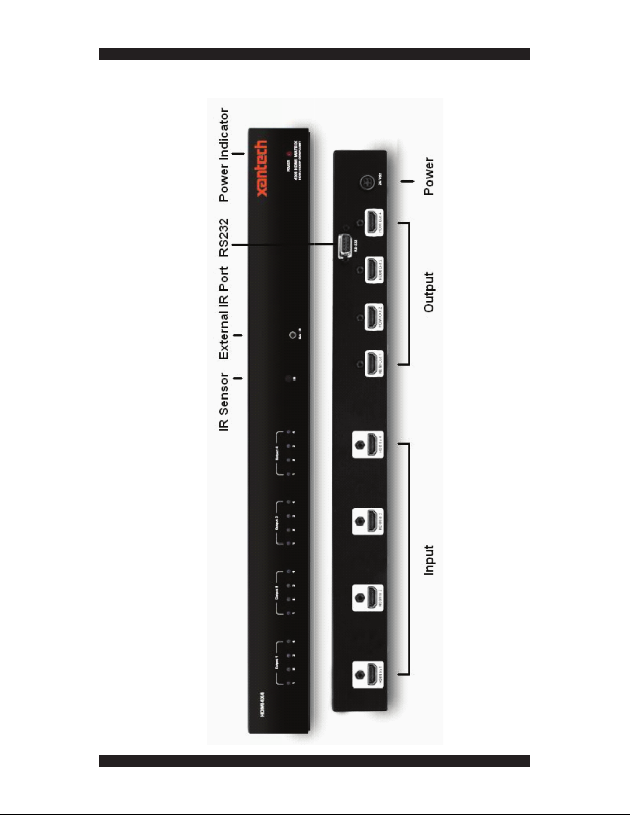
FRONT PANEL LAYOUT
-2-
Page 5

OPERATION NOTES
PLEASE READ THESE NOTES BEFORE INSTALLING OR
OPERATING THE HDMI4X4 MATRIX SWITCHER
The 4X4 HDMI Matrix is housed in a metal box for better RF shielding.•
The 4X4 HDMI Matrix works with all DVI and HDMI displays.•
The 4X4 HDMI Matrix supports both AUDIO and VIDEO signals.•
The 4X4 HDMI Matrix is fully HDCP compliant.•
VIDEO COMPATIBILITY NOTE
An HDMI source connects to the HDMI4X4 Matrix Switcher with four input
cables and four output cables. Output devices are examined to obtain an
EDID, or a data record of the performance characteristics of the display devices. The default behavior of this 4X4 HDMI Matrix is to generate an EDID
based on the common audio and video features of all connected output
display devices. (Please see EDID Mode 6 on Page 5). For example, the
display with the lowest native resolution will set the video resolution for all
connected display devices.
INSTALLATION INSTRUCTIONS
Connect all HDMI/DVI input sources to the HDMI input jacks on the 4X4
HDMI Matrix, using supplied cables (a DVI source may be connected using a
DVI-to-HDMI adapter cable, sold separately). Connect the HDMI/DVI displays
to the HDMI output jacks on the 4X4 HDMI Matrix. Connect the 24VDC power
tip to the 4X4 HDMI Matrix and plug the AC power cord to a free wall socket.
Beautiful, vibrant HD video and multichannel digital audio (if using HDMI) will
now be present at the HD display device.
Controlling the 4X4 HDMI Matrix using the RMT16-IR is done as follows:
Press Buttons To Obtain Switch Behavior
1 to 4 OUTPUT 1: View Source 1, 2, 3, 4
5 to 8 OUTPUT 2: View Source 1, 2, 3, 4
9 to 12 OUTPUT 3: View Source 1, 2, 3, 4
13 to 16 OUTPUT 4: View Source 1, 2, 3, 4
-3-
Page 6

RMT16-IR INSTALLATION
Remove battery cover from the back of the RMT16-IR remote.1.
Verify that DIP switches 1 & 2 are in the down (OFF) position.2.
Insert the battery; hold the battery so that you can see the positive 3.
side facing up. The side that is not marked must be facing down.
Test the RMT16-IR remote by pressing ONLY one button at a time. 4.
The indicator light on the remote will fl ash once each time you
press a button. WARNING: Do not press multiple buttons simultaneously and do NOT press buttons rapidly. These actions will cause
the remote to reset and steps 1-4 will have to be repeated.
Note: The RMT16-IR ships with two batteries. One battery is re-5.
quired for operation, the second battery is complimentary
.
-4-
Page 7

CUSTOM EDID CONFIGURATION VIA DIP SWITCHES
Extended display identifi cation data (EDID) is a data structure provided by a display to
describe its capabilities to any source that asks for it. The EDID includes manufacturer
name, product type, timings supported by the display, display size, luminance data, (for
digital displays only) pixel mapping data, supported audio channels and formats. This
information is used by the source to cater its output to resolutions and audio formats that
are supported by the display.
When displays are not properly recognized by HD source equipment, or when custom
display confi gurations are desired, you can manually adjust the EDID parameters to
achieve results using a bank of small switches inside the Xantech Splitter known as DIP
(Dual In-Line Package) switches.
To access the DIP switches, remove all screws from the bottom and sides of the Xantech
unit’s metal chassis. Carefully slide the unit apart. The bank of 8 DIP switches is located
on the main printed circuit board (PCB). Switches can be moved by a small screwdriver
or other pointed object. Once adjustments are complete, slide the unit back together and
replace all removed screws.
Additional EDID modes beyond the standard built-in modes are available and confi gured
using a combination of DIP switches 1, 2, 5 and 7. Please refer to the following page for a
list of the different EDID modes. The picture immediately below shows what a DIP switch
bank looks like:
-5-
Page 8

SETTING EDID MODES USING THE DIP SWITCH BANK:
EDID Mode 0 (Switch 1=OFF Switch2=OFF Switch5=ON) -EDID is copied from the
device connected to the fi rst active HDMI output port. - All features newer than HDMI
1.2 are cleared.
EDID Mode 1 (Switch 1=ON Switch2=OFF Switch5=ON) -Same as Mode 0 and adds
basic audio support.
EDID Mode 2 (Switch 1=OFF Switch2=ON Switch5=ON) -Same as Mode 0 and adds
full audio support.
EDID Mode 3 (Switch 1=ON Switch2=ON Switch5=OFF) -EDID is generated based on
the common video and audio features of all of the connected output devices.
EDID Mode 4 (Switch 1=OFF Switch2=ON Switch5=OFF) -Same as Mode 3 and adds
basic audio support.
EDID Mode 5 (Switch 1=ON Switch2=OFF Switch5=OFF) -Same as Mode 3 and adds
full audio support.
EDID Mode 6 (Switch 1=OFF Switch2=OFF Switch5=OFF) DEFAULT -EDID is
generated based on the common video features of all of the connected devices and the
combined audio features of all of the connected output devices.
EDID Mode 7 (Switch 1=ON Switch2=ON Switch5=ON) -EDID is passed unmodifi ed
from the device connected to the fi rst active output port.
EDID Mode 8 (Switch 1=OFF Switch2=OFF Switch5=OFF Switch7=ON) -Preloaded
generic 1080p EDID is used.
EDID Mode 9 (Switch 1=ON Switch2=ON Switch5=OFF Switch7=ON) -Same as Mode
8 with modifi cations to limit HPD (hot plug detect) events.
-6-
Page 9

Resolving Infrared Code Confl icts
In the event of IR confl icts, please do the following:
Remove the battery cover from the back of the RMT16-IR remote.1.
Locate the DIP Switches above the batteries.2.
Switch the DIP Switches on the RMT16-IR to any of the combina-3.
tions pictured below.
DIP Switches 1 and 2 in the RMT16-IR infrared remote correspond 4.
with DIP Switches 3 and 4 inside the 4X4 HDMI Matrix respectively.
Switch the DIP switches inside the 4X4 HDMI Matrix to match the
same Remote Channel as the RMT16-IR.
The 4X4 Matrix is now set to a new IR Code.5.
-7-
Page 10

RS-232 INTERFACE
ASCII Binary
1 1 0011 0001
2 2 0011 0010
3 3 0011 0011
4 4 0011 0100
5 5 0011 0101
6 6 0011 0110
7 7 0011 0111
8 8 0011 1000
9 9 0011 1001
a 10 0110 0001
b 11 0110 0010
c 12 0110 0011
d 13 0110 0100
e 14 0110 0101
f 15 0110 0110
g 16 0110 0111
RS232 Settings
Bits per second 19200
Data bits 8
Parity None
Stop bits 1
Flow Control None
-8-
Page 11

4X4 HDMI RACK MOUNT DIAGRAM
-9-
Page 12

SPECIFICATIONS
Video Amplifi er Bandwidth 1.65 Gbps
Input Video Signal 1.2 volts p-p
Input DDC Signal 5 volts p-p (TTL)
Single Link Range 1080p / 1920 x 1200
HDMI Input/Output Connector Type A 19-pin Female
Remote Control Port RS-232 Female, Mini-Stereo
Power Consumption 60 watts (max)
Power Supply 24V DC
Dimensions 17” W x 1.75” H x 5.875” D
Shipping Weight 10 lbs.
Technical Support
Hours: 7AM-5:30 PM PST
Phone: 800.843.5465
press 2 for Tech Support
FAX: 800.492.6832
e-mail: tech@xantech.com
HDMI4X4 User Manual © 2007 Xantech Corporation
This document is copyright protected. No part of this manual may be copied or
reproduced in any form without prior written consent from Xantech Corporation.
Xantech Corporation shall not be liable for operational, technical, or editorial
errors/omissions made in this document. Xantech is a registered trademark of
Xantech Corporation. All rights reserved.
Document Number 08905129A
Mailing Address
Xantech Corporation
13100 Telfair Avenue, 2/F
Sylmar, CA 91342
-10-
Page 13

Page 14

www.xantech.com
 Loading...