

Page 1

INSTALLATION INSTRUCTIONS
D5IP
DIGI-5 Source Input Plate
Digital Distribution System
08905155A - 1 -
Page 2

Introduction
Exceptional Performance
The D5IP Digital Distribution System Input Plate allows a Local Source (a source located within a
remote room away from the main distribution system) to be connected to the main distribution
system. It can easily connect with the D5KP Keypad Amplifier and the D5SH Digital Distribution
System Hub. The D5IP provides connections for Analog Audio, Digital Optical Audio, Digital Coaxial
Audio, and IR Control.
About DIGI-5 Technology
DIGI-5 is a revolutionary new technology standard that provides a complete end-to-end digital audio
solution over CAT-5 wiring. DIGI-5 is based on advanced digital distribution and amplification circuits
that allow multi-room audio systems to be installed quickly and cost effectively.
DIGI-5 is a collaboratively developed technology that is licensed by the Linear Home Technology
Group and is being initially integrated on a Linear group-wide basis, targeted to expand market and
consumer acceptance of such systems.
Features
• Local Source Input Plate for D5KP
• Remote Source Input Plate for Digital Audio Distribution Hubs (D5SH)
• Accepts Analog Audio, Digital Optical Audio, Digital Coaxial Audio
• Converts Analog Audio to Digital
• 3-Position Source Selection Input Switch
• Clipping Indicator
• Gain adjustment
• IR Output Jack for Source Control
D5IP Accessories
• D5PS Digital Audio Power Supply (required)
• D5KP Amplified Keypad (required)
• D5SH Distribution Hub (required)
• D5MR Slim-line IR Remote
• D5LR Learning Remote Control
08905155A - 2 -
Page 3

Planning
Before installing the D5IP, it is essential to have a detailed and accurate system design. The first step
to a good design is to map the system. It is advisable to mark up a copy of the house floor plan with
speaker, keypad and equipment locations, etc. Make sure that all locations are decided upon before
pre-wiring so that all necessary wiring and installation hardware is in place.
It is essential that ALL system components are accounted for prior to the pre-wire stage. After
establishing design goals, make a detailed list of all components. Include source equipment, keypad,
expansion hubs, local source wall plates, IR emitters, etc.
Pre-Construction
In a pre-construction installation, walls and ceilings are open with no drywall installed. This is
desirable and allows the installer greater access than in retro-fit applications. Before actually running
any wire or cable, take the time to look around each room or area of the house and plan your wire
paths for maximum efficiency. Look for routes through uncluttered parts of the stud wall or ceiling that
allow you to group all low-voltage (video, speaker wires, CAT-5, telephone, etc.) wires wherever
possible. It is a good practice to label both ends of all cables and to protect wires by tying a plastic
bag over the ends.
Note: Do not run low-voltage wires closer than 12" from high-voltage wires. If necessary, cross lowvoltage wires at a 90º angle to prevent interference.
Retro-Fit Wiring/ Post Construction
Retro-fit installations are more difficult to complete than pre-construction because walls and ceilings
are intact. Typically wires must be fished into position through walls, floors and ceilings. Holes must
be cut; speakers mounted directly in the ceiling or walls with no rough-in brackets and keypads and
local source wall plates must be mounted in existing drywall.
08905155A - 3 -
Page 4
Pre-Wiring
D5IP Digital Audio Source Input Plate to D5KP Keypad and D5SH Hub
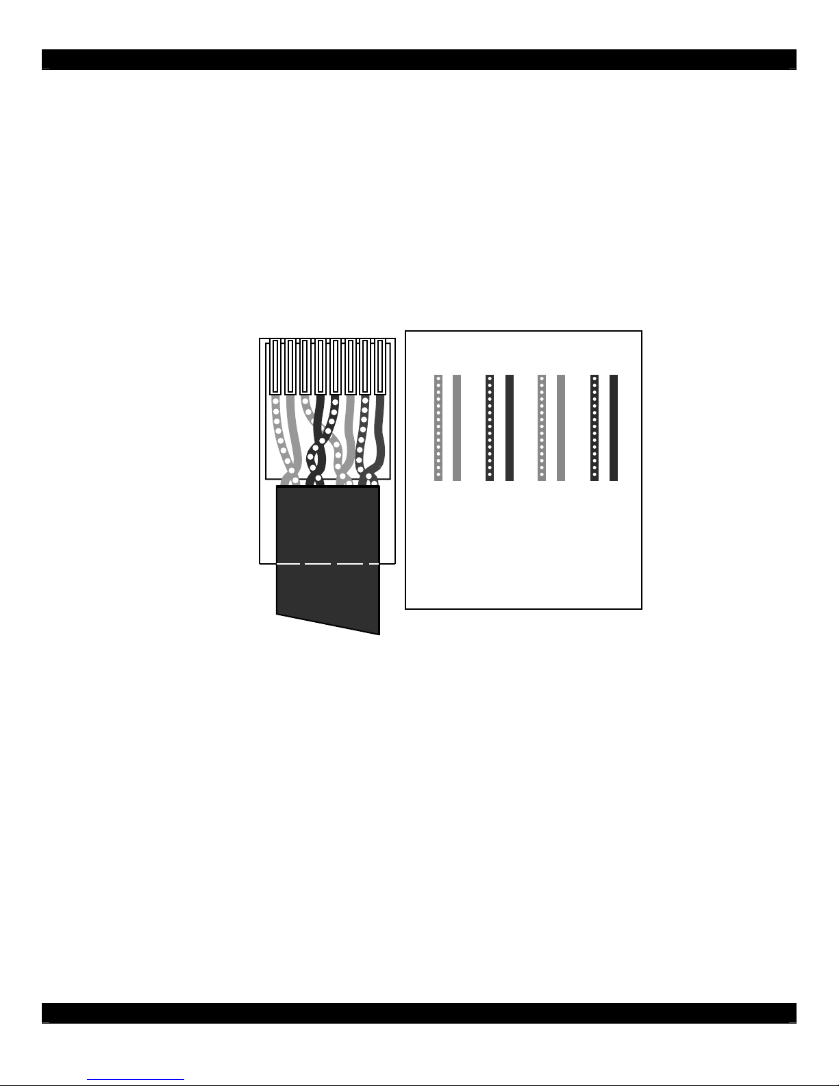
The D5IP and all associated components are wired using CAT-5 terminated to the T-568A Wiring
Standard (Figure 2.1). When pre-wiring, run lengths of CAT-5 from the pre-determined equipment
location (the “head-end”) to each Amplifier Keypad location. The CAT-5 routes all audio, power, IR
and status information needed for full system operation. Use a 110 Punchdown tool to connect the
CAT-5 wiring to the Digital Audio Distribution Hub.
Note: For maximum performance over long runs (more than 150 ft) run an additional 16AWG 2conductor wire for external power.
12345678
12 34 56 78
BLUE
ORANGE
BLUE/WHITE
ORANGE/WHITE
BROWN
BROWN/WHITE
Shown tab
down
GREEN
GREEN/WHITE
Figure 2.1: T-568A Wiring Standard
Amplifier Keypad to Speakers
Run 16AWG 2-conductor stranded copper speaker wire between Amplifier Keypad locations and
speaker locations.
08905155A - 4 -
Page 5

D5IP
Connector Function
1 Analog Audio Input (L/R)
2 Digital Coaxial Audio Input
Connect analog audio source using RCA
cables.
Connect digital audio sources using Digital
Coaxial cable.
3 IR Output Source-specific IR port to control audio source.
4 Source Input Switch
5 Digital Optical Audio Input
6 Clipping Indicator LED
Select between Digital Coaxial, Digital Optical
or RCA connection.
Connect digital audio sources using Digital
Optical cable.
Indicates when connected source is ‘clipping’
the input. ‘Clipping’ results in distorted audio.
08905155A - 5 -
Page 6

Connector Function
1 Gain Adjustment DIP Switches
Adjust Input GAIN from analog sources to
avoid distortion.
Connects to D5KP Keypad\Amplifier, D5R44H
2 Output RJ-45 Connector
(D5RE6H) or D5M44H (D5M14H) Digital Audio
Distribution Hubs.
Installation
The D5IP is designed to mount in a standard single-gang rough-in box (J Box). Mount the unit in
close proximity to the location of the source that will be connected to it.
Note: Do not mount the D5IP in the same rough-in box as the high voltage devices such as electrical
outlets or switches.
After running CAT-5 and terminating the ends, route the wire into the back of the rough-in box,
connect it to the RJ-45 connector on the rear of the D5KP, and mount using the 2 provided screws.
08905155A - 6 -
Page 7

Connections
Connections for the D5IP consists of:
1. Audio Source Connections – Front
2. IR Control - Front
3. D5KP Amplified Keypad - Rear
4. D5XH DDS Expansion Hub – Rear
5. D5SH, D4SH4 DDS Wall-Mount Hub – Front
Source Connections
Sources are connected to the D5IP in one of three ways:
1. Analog
2. Digital Coaxial
3. Digital Optical
For best sound quality, use one of the Digital connection methods if the Source has this type of
output. For sources that do not have Digital outputs, use the Analog option.
Note 1: Make sure that the D5IP’s Source Input Switch is correctly set for the type of connection used.
Note 2: Multi-channel digital audio formats (5.1, 7.1, etc.) are not supported by the D5IP. Most audio/video sources allow you to change the digital output
to PCM Stereo. In most cases, this will allow multi-channel audio sources to output a “summed” stereo signal through the digital output. Consult the
audio/video source manual for details.
Note 3: Some audio sources which utilize a digital output require that you enable the digital output before it will function. If there is no audio present,
check the setup menu of the audio source to confirm that the digital output is enabled.
Analog (AUDIO IN L/R)
Use RCA audio patch cables to connect an audio source that does not have a Digital output.
NOTE: Be sure the RCA/OPT/COAX switch is ‘up’ and set to ‘RCA’.
08905155A - 7 -
Page 8

Digital Optical (OPTICAL IN)
Use a Digital Optical Cable to connect an audio source that has a Digital Optical output.
NOTE: Be sure the RCA/OPT/COAX switch is ‘middle’ and set to ‘OPT’.
Note: Multi-channel digital audio formats (5.1, 7.1, etc.) are not supported by the D5IP. Most audio/video sources allow you to change the digital output
to PCM Stereo. In most cases, this will allow multi-channel audio sources to output a “summed” stereo signal through the digital output. Consult the
audio/video source manual for details.
Digital Coaxial (COAX IN)
Use a Digital Coaxial Cable to connect an audio source that has a Digital Coaxial output.
NOTE: Be sure the RCA/OPT/COAX switch is ‘down’ and set to ‘COAX’.
Note: Multi-channel digital audio formats (5.1, 7.1, etc.) are not supported by the D5IP. Most audio/video sources allow you to change the digital output
to PCM Stereo. In most cases, this will allow multi-channel audio sources to output a “summed” stereo signal through the digital output. Consult the
audio/video source manual for details.
08905155A - 8 -
Page 9

IR OUT
Connect a standard IR Emitter (283D, for example) from the IR OUT port on the front of the D5IP to
the IR receiver on the front of the audio source. For sources that have an IR Input port on the back of
the unit, use a 3.5mm to 3.5mm mono interconnect cable instead.
Rear Connections
D5KP Amplified Touch Pad
When utilizing the D5IP as a means to connect a Local Source to a specific zone of a D5RH-based
system, rear connections consists of plugging in a CAT-5 wire terminated to an RJ-45 connector
wired to T-568A standard to the RJ-45 jack on the rear of the D5IP. The other end simply plugs into
the LOCAL PORT RJ-45 jack on the rear of the zone’s D5KP Amplified Touch Pad.
D5XH DDS Expansion Hub
When utilizing the D5IP as a means to connect an audio source to a D5XH DDS Expansion Hub in
stand-alone mode, rear connections consists of plugging in a CAT-5 wire terminated to an RJ-45
connector wired to T-568A standard to the RJ-45 jack on the rear of the D5IP. The other end simply
plugs into the SOURCE LOOP IN RJ-45 jack on the rear of the D5XH.
Settings/Adjustment
There is one LED on the front of the D5IP that monitors the input level of the connected source.
There are two sets of DIP switches on the rear of the unit (marked “GAIN”) designed to adjust the
input level of the connected source.
Note: The GAIN DIP switches are only for Analog Inputs. The Digital Coaxial and Digital Optical
Inputs do not utilize these switches.
08905155A - 9 -
Page 10

Adjusting Analog Audio Source
Input Level
Once all connections are made, the Analog Audio Source should be adjusted to prevent clipping
(distortion) before the D5IP is mounted in place. To adjust the Analog Audio Source Input Level:
1. Ensure that the Analog Audio Source is connected properly.
2. Power up the source and turn on an audible signal (Press PLAY, tune to a station, etc.).
3. Select the Source from the zone’s D5KP Touchpad. If it is a Local Source connected to a
D5KP, select LOCAL. If it is a System Source connected to a D5XH, select the appropriate
Source Input on the Zone’s D5KP.
4. Adjust the zone’s volume to a normal, comfortable listening level.
5. Observe the CLIP LED on the front of the D5IP. If it lights up constantly or consistently, the
source’s output level is too high and needs to be adjusted.
6. Adjust the GAIN DIP switches according to the following table:
Setting Function
All Down No GAIN
DIP Switch 1 & 3 UP +4dB GAIN
DIP Switch 2 & 4 UP +8dB GAIN
DIP Switch 1, 2, 3 & 4 UP +10dB GAIN
Note 1: Try each setting and monitor the CLIP LED until it does not illuminate.
Note 2: GAIN adjustment must be set for both Right and Left Inputs.
Both settings should be the same.
7. Mount the D5IP and install Trim Ring.
Specifications
Sampling Frequency 48kHz
Digital Audio Resolution 24 Bit, Stereo
THD+Noise Full Scale 0.004%
Dynamic Range 96dB
L/R Crosstalk @ 1kHz -90dB
Frequency Response 20Hz-20kHz +/- 0.1dB
Max Output Distance 800 ft
GAIN DIP Switches
All DOWN
DIP Switch 1&3 Up
DIP Switch 2&4 Up
DIP Switch 1,2,3&4 Up
Dimensions
H x W x D 4 1/4" x 1 3/8" x 2 3/4"
Weight 0.28lbs (0.13kg)
No GAIN
+4dB GAIN
+8dB GAIN
+10dB GAIN
(10.8 cm x 3.5 cm x 7.0 cm)
08905155A - 10 -
Page 11

Safety Information
NOTE: This equipment has been tested and found to comply with the limits for a Class B digital device, pursuant to part
15 of the FCC Rules. These limits are designed to provide reasonable protection against harmful interference in a
residential installation. This equipment generates, uses and can radiate radio frequency energy and, if not in-stalled and
used in accordance with the instructions, may cause harmful interference to radio communications. However, there is no
guarantee that interference will not occur in a particular installation.
If this equipment does cause harmful interference to radio or television reception, which can be determined by turning the
equipment off and on, the user is encouraged to try to correct the interference by one or more of the following measures:
• Reorient or relocate the receiving antenna.
• Increase the separation between the e quipment and receiver.
• Connect the equipment into an outlet on a circuit different from that to which the receiver is connected.
• Consult the dealer or an experienced radio/TV technician for help.
CAUTION: Changes or modifications not expressly approved by Xantech could void the user’s authority to operate the
equipment
Caring For the D5IP
Clean only with a dry soft cloth.
It is important to properly care for your D5IP Digital Audio Source Input Plate. Follow these guidelines to ensure your
device is preserved and protected.
• Do not expose the D5IP to rain, liquids or moisture for an extended perio d of time.
• Do not expose the D5IP to temperature extremes.
• Do not place any objects on top of the D5IP to prevent chassis dam age.
Operating Temperatures & Environments
• Operating Temperature: 32-104°F (0-40° C)
• Humidity: 0-90%
Precautions
• Always exercise care when operating the D5IP Digital Distribution System Input Plate.
• Do not install near any heat source s such as radiators, heat registers, stoves, or other apparatus (including
amplifiers) that produce heat.
• In the unlikely event that smoke, abnormal noise, or strange odor is present, immediately power the D5IP off.
Please report the problem to your dealer immediately.
• Never attempt to disassemble the D5IP. You will lose any product warranty on the unit.
Xantech Corporation
13100 Telfair Ave. 2F, Sylmar CA 91342 | Xantech.com
Installation Instructions, D5IP © 2008 Xantech Corporation
This document is copyright protected. No part of this manual may be copied or reproduced in any form without prior written consent from Xantech
Corporation. Xantech Corporation shall not be liable for operational, technical, or editorial errors/omissions made in this document.
Document # 08905155A
08905155A - 11 -
Page 12

Xantech Limited Warranty
Xantech Corporation (“Xantech”) warrants to the holder of a valid proof of purchase as the first end-user purchaser
(“You”), its products to be free from defects in materials and workmanship for the periods specified belo w from the date o f
purchase. This limited warranty extends only to You for product purchased and used in the United States of America. For
product purchased outside of the United States of America, the terms of this warranty apply EXCEPT that You must
contact the Xantech authorized distributor in your region for warranty services. Product is not intended for end user
installation. If within the applicable warranty period above You discover such item was not as warranted above and You
promptly notify Xantech in writing, Xantech shall repair or replace the items at its option. Xantech may elect which remedy
or combination of remedies to provide in its sole discretion. Xantech may use functionally equivalent
reconditioned/refurbished/pre-owned or new products or parts under this limited warranty. This warranty sh all not apply
(a) to product which shall have been installed by other than an authorized Xantech installer, (b) to installed product which
is not installed to Xantech’s specifications, (c) to product which shall have been repaired or altered by others than
Xantech, (d) to charges for installation or set up or adjustment of customer controls, (e) to product that has suffered
normal cosmetic deterioration (f) to product which shall have been subjected to negligence, misuse, abuse, accident, or
damage by circumstances beyond Xantech’s control, including, bu t not limited to, lightning, flood, electrical surge,
tornado, earthquake, or any other catastrophic events beyond Xantech’s control, or (g) to product which shall have been
subjected to improper operation, connected equipment failure or malfunction, inadequate packing or shipping damage,
maintenance or storage, or to other than normal use of service. The foregoing warranties do not cover reimburseme nt for
labor, transportation, shipping, removal, installation, or other expenses which may be incurred in connection with repair or
replacement. All claims for product shipping damage must be processes within 3 days of receipt by You.
A Xantech Return Authorization (RA) must be obtained from Xantech by You, your installer or your distributor for Product
covered under this warranty. Covered product must be sent to Xantech together with proof of purchase, RA numbe r,
prepaid and insured to Xantech. Freight collect shipments will be refused. Risk of loss or damage in transit is borne by the
sender. Xantech's warranty does not cover Products which have been received improperly pa ckaged, altered, or
physically damaged. Products will be inspected upon receipt.
Except as may be expressly provided and authorized in writing by Xantech, Xantech shall not be subject to any other
obligations or liabilities whatsoever with respect to equipment manufactured or sold by Xantech or services rendered by
Xantech.
THE FOREGOING WARRANTIES ARE EXCLUSIVE AND IN LIEU OF ALL OTHER EXPRESSED AND IMPLIED
WARRANTIES, INCLUDING BUT NOT LIMITED TO IMPLIED WARRANTIES OF MERCHANTABILITY AND FITNESS
FOR A PARTICULAR PURPOSE.
ATTENTION: TO OUR VALUED CONSUMERS
To insure that consumers obtain quality pre-sale and after-sale support and service, Xantech products are sold
exclusively through authorized dealers and authorized distributors. The warranties on Xante ch products are NOT VALID if
the products have been purchased from an unauthorized dealer or distributor. In order to determine if your Xantech reseller is authorized, please call Xantech (800) 843 - 5465.
XANTECH PRODUCT
(go to Xantech.com/warranty for model numbers)
IR Receivers and IR Emitters Limited Lifetime
A/V distribution and Control Limited Lifetime
Remote Control Switchers Limited Lifetime
Modules and Connecting Blocks Limited Lifetime
Accessories Limited Lifetime
Speakers Limited Lifetime
Volume Controls and Speaker Selectors 5 year Limited
DIGI-5, MRC, BX, ZPR and Commercial Products 2 year Limited
Amplifiers 2 year Limited
Control Interfaces 2 year Limited
Hand Held Remote Controls 1 year Limited
SPLCD Product 1 year Limited
Source Components 1 year Limited
(Effective for products sold after July 1, 2006)
WARRANTY DURATION
08905155A - 12 -
 Loading...