

Page 1

Reference Manual &
Programming Guide
Room Monitor – Web Intelligent Controller Model: CRM-WIC
Page 2

Contents
CONTENTS ......................................................................................................................................................... 2
INTRODUCTION ................................................................................................................................................ 6
BOX CONTENTS ................................................................................................................................................7
BOX CONTENTS FOR THE CRM-WIC...............................................................................................................7
HARDWARE USER INTERFACE .....................................................................................................................8
HARDWARE USER INTERFACE FOR THE CRM-WIC.......................................................................................... 8
SPECIFICATIONS ........................................................................................................................................... 10
PIN-OUTS..................................................................................................................................................... 10
FACTORY DEFAULT CONFIGURATIONS .................................................................................................. 11
NETWORK SETTINGS..................................................................................................................................... 11
SERIAL / DIPSWITCH SETTINGS...................................................................................................................... 11
QUICK START.................................................................................................................................................. 12
POWERING UP ..............................................................................................................................................12
DETERMINE CRM-WIC CONNECTION ...........................................................................................................12
ENABLING / DISABLING DHCP BY RESET ...................................................................................................... 13
ACCESSING THE CRM-WIC THROUGH THE NETWORK ...................................................................................14
CONFIGURING THROUGH THE ADMIN WEB PAGES.......................................................................................... 14
CONFIGURING THROUGH THE BOOT MENU .................................................................................................... 14
USING THE CRM-WIC.................................................................................................................................... 15
TESTING HARDWARE .................................................................................................................................... 15
UPLOADING FIRMWARE UPGRADES............................................................................................................... 15
VIEWING SERVER LOGS ................................................................................................................................15
UPLOADING CUSTOM WEB PAGES................................................................................................................. 15
MANAGING CUSTOM EVENTS........................................................................................................................ 15
USING REMOTE PROCEDURE CALLS (RPCS).................................................................................................. 15
BOOT MENU REFERENCE.............................................................................................................................17
ACCESSING THE BOOT MENU WITH A SERIAL CONNECTION ........................................................................... 17
0: DISPLAY CURRENT SETTINGS ....................................................................................................................18
1: RESTORE FACTORY DEFAULTS .................................................................................................................. 18
2: CONFIGURE IP SETTINGS........................................................................................................................... 18
3: SET PASSWORD......................................................................................................................................... 18
4: SET HOST NAME....................................................................................................................................... 18
5: DOWNLOAD NEW FIRMWARE ....................................................................................................................19
6: LAMP TEST............................................................................................................................................... 19
7: HARDWARE TEST...................................................................................................................................... 19
8: ERASE ALL FILES...................................................................................................................................... 19
9: OEM FUNCTIONS ..................................................................................................................................... 19
ADMIN WEB PAGES........................................................................................................................................20
SETUP ..........................................................................................................................................................21
Firmware Version........................................................................................................................................ 21
Date / Time..................................................................................................................................................21
Network Settings ......................................................................................................................................... 22
Host Name...................................................................................................................................................22
System Password......................................................................................................................................... 22
IP Access Table........................................................................................................................................... 22
DIAGNOSTICS ............................................................................................................................................... 23
2
Page 3

SERIAL: Serial Port Diagnostics..................................................................................................................24
MEMORY: System Memory Information.....................................................................................................26
LOG: Log Files............................................................................................................................................27
F/W: Firmware ............................................................................................................................................ 28
EVENTS (SEE SECTION: THE EVENT MANAGER) ............................................................................................. 29
FILES ........................................................................................................................................................... 29
THE EVENT MANAGER ................................................................................................................................. 30
OVERVIEW OF EVENTS, ACTIONS, & VARIABLES ........................................................................................... 30
THE EVENT MANAGER WEB PAGE ................................................................................................................31
EVENTS........................................................................................................................................................ 32
Creating and Editing Events......................................................................................................................... 32
Types of Events........................................................................................................................................... 32
Other Event Options .................................................................................................................................... 33
ACTIONS ......................................................................................................................................................34
Creating and Editing Actions .......................................................................................................................34
Types of Actions..........................................................................................................................................34
Action Timing Options ................................................................................................................................ 35
VARIABLES ..................................................................................................................................................35
Creating and Editing Variables.....................................................................................................................36
Types of Variables....................................................................................................................................... 37
EXPRESSIONS ............................................................................................................................................... 38
Interpreting Values as Expressions............................................................................................................... 38
Evaluation of Expressions............................................................................................................................ 38
Operators..................................................................................................................................................... 39
Escaping Special Characters.........................................................................................................................45
REMOTE PROCEDURE CALLS..................................................................................................................... 46
RPC SERVER LOGS....................................................................................................................................... 46
SYNTAX FOR HTTP POST.............................................................................................................................. 46
Call Tokens ................................................................................................................................................. 46
Response Tokens......................................................................................................................................... 47
EXAMPLE #1: Serial_GetSettings............................................................................................................... 47
EXAMPLE #2: Net_GetSubnetMask ........................................................................................................... 47
FAULT CODES .............................................................................................................................................. 48
USING MACROMEDIA FLASH......................................................................................................................... 48
STEP 1: Pass CRM-WIC IP Address to Flash............................................................................................... 48
Step 2: Call RPC with HTTP Post................................................................................................................ 49
Step 3: Response Tokens..............................................................................................................................50
VISUAL BASIC SCRIPTING .............................................................................................................................50
NOTE ON ERROR CHECKING .......................................................................................................................... 51
ERROR INFORMATION METHODS ................................................................................................................... 51
GetLastErrorCode ( ) ...................................................................................................................................51
GetLastErrorString ( ).................................................................................................................................. 51
GetLastExtendedErrorString ( ).................................................................................................................... 52
GENERAL INFORMATION METHODS ............................................................................................................... 52
AllState_Get ( )............................................................................................................................................52
Time_GetDate ( )......................................................................................................................................... 53
Time_Sleep ( Milliseconds ) ........................................................................................................................53
Net_GetIPAddress ( )...................................................................................................................................53
Net_GetSubnetMask ( )................................................................................................................................54
SERIAL METHODS ......................................................................................................................................... 55
Serial_GetSettings ( Port )............................................................................................................................55
Serial_Send ( Port, Msg, MaxWaitMS ) ....................................................................................................... 55
Serial_Read ( Port )......................................................................................................................................56
Serial_ClearReadBuffer ( Port ) ................................................................................................................... 56
Serial_ReadBufferCount ( Port ) .................................................................................................................. 56
EVENT METHODS ......................................................................................................................................... 57
3
Page 4

GetEventByIdx ( Idx ).................................................................................................................................. 57
GetEventByName ( Name )..........................................................................................................................57
GetEventIdxById ( EventId ) .......................................................................................................................58
GetEventName ( EventId )........................................................................................................................... 58
GetEventType ( EventId ) ............................................................................................................................ 58
GetEventOption ( EventId, OptionType ) ..................................................................................................... 59
GetEventConcurrent ( EventId )................................................................................................................... 60
GetEventSource ( EventId )..........................................................................................................................60
GetEventMatch ( EventId ) .......................................................................................................................... 61
GetEventSchClockType ( EventId ).............................................................................................................. 61
GetEventSchRecurType ( EventId ).............................................................................................................. 62
GetEventSchMaskOrDay ( EventId )............................................................................................................62
GetEventSchMonth ( EventId ) .................................................................................................................... 63
GetEventSchYear ( EventId )....................................................................................................................... 64
GetEventSchRecurEveryN ( EventId )..........................................................................................................64
GetEventSchHour ( EventId ).......................................................................................................................64
GetEventSchMinute ( EventId ) ................................................................................................................... 65
GetEventSchSecond ( EventId ) ................................................................................................................... 65
SetEventById ( EventId, Name, Type, Concurrent, Source, Match )..............................................................66
SetEventByName ( Name, Type, Concurrent, Source, Match )......................................................................66
SetEventOption ( EventId, OptionType, OptionVal ).................................................................................... 67
SetEventSchedule ( EventId, Recur, MaskOrDay, Month, Year, RecurEveryN, Hour, Minute, Second )........ 69
CloneEventById ( EventId, CloneActions, NewName )................................................................................ 70
AddEvent ( Name, Type, Concurrent, Source, Match ) ................................................................................. 70
DeleteEventById ( EventId )........................................................................................................................ 71
DeleteEventByName ( Name ) ..................................................................................................................... 71
SortEvents ( SortType, Direction ) ............................................................................................................... 72
GetEventCount ( )........................................................................................................................................ 72
ACTION METHODS........................................................................................................................................ 73
GetActionByIdx ( EventId, Idx ).................................................................................................................. 73
GetActionByName ( EventId, Name ) .......................................................................................................... 73
MoveActionByIdx ( EventId, Idx, Where )................................................................................................... 74
GetActionName ( ActionId )........................................................................................................................ 74
GetActionType ( ActionId ) ......................................................................................................................... 74
GetActionOption ( ActionId, OptionType ).................................................................................................. 75
GetActionDelay ( ActionId )........................................................................................................................ 76
GetActionDutyCycle ( ActionId )................................................................................................................. 76
GetActionStopAfter ( ActionId ).................................................................................................................. 76
GetActionPort ( ActionId )...........................................................................................................................77
GetActionOutput ( ActionId )....................................................................................................................... 77
SetActionById ( ActionId, Name, Type, Delay, DutyCycle, StopAfter, Port, Output )................................... 78
SetActionByIdx ( EventId, Idx, Name, Type, Delay, DutyCycle, StopAfter, Port, Output ) ........................... 80
SetActionByName ( EventId, Name, Type, Delay, DutyCycle, StopAfter, Port, Output ) ..............................81
SetActionOption ( ActionId, OptionType, OptionVal )................................................................................. 82
AddActionByEvId ( EventId, Name, Type, Delay, DutyCycle, StopAfter, Port, Output ) ..............................83
AddActionByEvName ( EventName, Name, Type, Delay, DutyCycle, StopAfter, Port, Output )...................84
DeleteActionById ( ActionId )..................................................................................................................... 86
DeleteActionByIdx ( EventId, Idx ).............................................................................................................. 87
DeleteActionByName ( EventId, Name )...................................................................................................... 87
SortActions ( SortType, Direction ).............................................................................................................. 87
GetActionCount ( EventId )......................................................................................................................... 88
VARIABLE METHODS.................................................................................................................................... 88
GetVariableByIdx ( Idx ) ............................................................................................................................. 88
GetVariableByName ( Name ) ..................................................................................................................... 89
GetVariableName ( VarId ).......................................................................................................................... 89
GetVariablePersist ( VarId )......................................................................................................................... 89
GetVariableType ( VarId )........................................................................................................................... 90
GetVariableDefault ( VarId )........................................................................................................................ 90
4
Page 5

GetVariableValue ( VarId ).......................................................................................................................... 90
SetVariableById ( VarId, Name, Type, Default, Value, Persist ) ................................................................... 91
SetVariableByName ( Name, Type, Default, Value, Persist )........................................................................ 93
AddVariable ( Name, Type, Default, Value, Persist ).................................................................................... 94
DeleteVariableById ( VarId )....................................................................................................................... 95
DeleteVariableByName ( Name )................................................................................................................. 96
SortVariables ( SortType, Direction )........................................................................................................... 96
GetVariableCount ( ).................................................................................................................................... 97
INDEX ................................................................................................................................................................ 98
LIMITED WARRANTY.................................................................................................................................... 99
5
Page 6
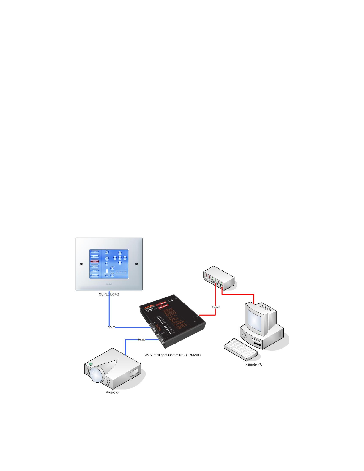
Introduction
Xantech’s Commercial Room Monitor – Web Intelligent Controller is a stand-alone room controller and
also the long awaited ‘glue’ piece providing dynamic RS232 feedback module from any RS232 device for
the Commercial CSPLCD TouchPanel displays.
On it’s own, the Web Intelligent Controller is an Event driven component with two RS232 ports
(configurable for RS422 and RS485) and a single IP port. The Event Manager is capable of Timed
Events, Calendar Events, Telnet and Serial Events as well as a full FTP site, Web Server and Email
Server.
Used as a Room Controller for a presentation system, the Web-Intelligent Controller can automatically,
every night at 12AM, turn the projector OFF if left on, check Bulb Life and if low email the IT or AV
specialist responsible!
When interfaced with the CSPLCD Commercial TouchPanel Display, the Web-Intelligent Controller can
send messages back to the TouchPanel allowing for Text Display, Numeric Display, Volume and
Indicator bars, ON/OFF indicators etc….. for full real-time data display. The IP port allows each room to
be accessible on the facilities IP network for Status display, remote centralized control as well as remote
diagnostics.
The following Manual, is an in-depth coverage of all features contained within the CRMWIC. For
Application specific examples, please refer to the “Web Intelligent Controller: Application & Quick-Start
Guide”.
6
Page 7

Box Contents
Box Contents for the CRM-WIC
Web Intelligent Controller Model:CRMWIC Power Adapter
7
Page 8

Hardware User Interface
Hardware User Interface for the CRM-WIC
8
Page 9

Hardware
User Interface
Notes See Also
1 Serial Ports 1 & 2 The serial ports enable RS-232 and RS-422/485
communications, supporting a wide range of
compatible electronics.
The actual connectors on the CRM-WIC are
DB-9 male ports. Your device or cable should
have a DB-9 female to connect.
2 LED Indicators
for Serial Ports
1 & 2
3 Dipswitch
Settings for
Serial Ports 1 &
2
4 Green LED
Indicator for
Power
5 Power Adapter
Port
There are two (2) sets of LEDs, one set for each
serial port. Each set consists of six (6) red
LEDs that indicate activity on the pins.
When using RS-232 communications, the six
LEDs indicate activity on the (from top down)
TX, RX, CTS, RTS, DTR, and DSR pins.
When using RS-422/485 communications, the
LEDs indicate activity on the corresponding TXA, RX-A, TX-B, and RX-B pins. For RS-422/485,
there is no activity on the CTS and RTS pins.
These dipswitches physically set the Baud Rate,
Number Bit, Parity, Stop Bits, RS-232 or RS422/485, and Handshaking for Serial Ports 1
and 2.
It is possible to override the dipswitch settings
by using the Admin Web Pages [Admin]
The green LED indicates that the CRM-WIC is
powered.
The CRM-WIC is powered using the included
Power Adapter. The smaller end of the Power
Adapter is plugged into this port.
Pin-Outs, page 10: DB-9 pinout diagram and labels.
Serial / Dipswitch Settings,
page 11: Setting options and
factory default settings.
Serial Settings - Dipswitch
Override, page 26: Settings
override from Admin Web
Pages., page 32: Tools on
Admin Web Pages.
Jump To [Events]
Jump to [Actions]
Jump to [Methods]
This section describes how to
power up your CRM-WIC
and access the configuration
options.
STEP 1: Powering Up, page
12: Quick start to powering
up the CRM-WIC.
6 Blue LED
Indicator for
Status
7 LAN Port The CRM-WIC may be connected to a network
8 Reset Pin The Reset Pin is a recessed button used in the
A slow blink generally indicates that the CRMWIC is ready to serve web and ftp requests.
[Indicators]
A repeating sequence of flashes indicates an
error.
The blue LED will also light when the reset pin
is pressed.
using a standard Ethernet cable in this port.
The green LED on the LAN port indicates that a
network has been detected.
The yellow LED on the LAN port indicates that
data is being transmitted through the port.
administration and maintenance of the CRMWIC.
Jump to LED Indicators
Jump to Network Access
Reset Function
9
Page 10

Specifications
Size
Weight
Power Adapter
Processor
Memory
Ports
Monitoring
Network Access
CRM-WIC Input
Voltage
Network Adapter
RS-232/RS-422/485
5.4" H x 4.4" W x 0.95" D √
0.6 lbs. √
12V DC 500mA
32-Bit √
Total RAM 32M
Total Flash 8M
Available Flash* 2.5M
10/100 LAN (RJ-45 / Ethernet) 1
RS-232/422/485 (Male DB9) 2
32-Bit Internal Clock/Calendar √
Web & FTP √
Min +8V, Typ +12V, Max +18V
10/100Mbits
15KB Protection 115KB Max
* Available Flash Memory may vary based on firmware version.
Pin-Outs
Port RS-232 RS-422/485
1 NC NC
2 RX RX -
3 TX TX -
4 DTR TX +
5 GND GND
6 DSR RX +
7 RTS Active Low
(0.5v)
8 CTS
9 NC NC
15 KΩ to
GND
10
Page 11

Factory Default Configurations
Network Settings
DHCP Enabled No
IP Address 10.10.10.10
Subnet Mask 255.255.255.0
Gateway 10.10.10.1
Subnet Mask CRM-WIC
Gateway admin
Serial / Dipswitch Settings
Note: Serial Settings are configurable by default in the Serial Diagnostic Web Setup Page (Jump to
Diagnostics)
Positions 1-4: Baud Rate (bps)
1 2 3 4
300 Off Off Off Off
600 Off Off Off
1200 Off Off
2400 Off Off
4800 Off
9600 Off
19200 Off
38000 Off
57600
115000
ON
ON
ON
ON ON
ON
Off Off
ON
Off
ON ON
ON ON ON
Off Off Off
Off Off
Position 5: Number Bits
5
8 Bits Off
7 Bits
ON
ON
Off
ON
Off
ON
Position 6-7: Parity
6 7
None Off Off
ON
ON
Off
Odd Off
Even
Position 8: Stop Bits
8
1 Bits Off
2 Bits
ON
Position 9: Serial Port
9
RS-232 Off
RS-422-485
ON
Position 10-11: Handshaking
10 11
None Off Off
ON
ON
Off
Hardware Off
Software
11
Page 12

Quick Start
This section describes how to power up your CRM-WIC and access the configuration options.
STEP 1: Powering Up
Locate the power adapter which came with your CRM-WIC. Plug the small end into the power supply
port on the upper right side of the CRM-WIC, and the large plug into a wall socket or compatible power
supply.
You should observe the following behavior in this order:
• The green Power LED will immediately light. It will remain lighted while the CRM-WIC is
plugged in.
• After approximately 5 seconds, ALL the LEDs will flash on.
• Almost immediately, all the LEDs will then flash off, EXCEPT the green Power LED and the
blue Status LED, which will remain lighted.
• About 10 seconds later, the RTS and DTR Serial LEDs for both serial ports will light on. In
addition, the LEDs for the four Digital I/O ports will also light on. The green Power LED
and the blue Status LED will still be steadily lighted at this point.
• After another 10 seconds or so, the blue Status LED should start blinking slowly.
A slow, steady blink on the blue Status LED indicates that the CRM-WIC is ready to connect to an IPbased LAN network and serve web and FTP requests.
Repeating multiples of fast flashes on the blue Status LED indicate errors.
STEP 2: Determine CRM-WIC Connection
Decide how you would like to connect to your CRM-WIC to configure it:
Connection Type Why use this connection type? What do I do next to connect this
way?
Connect the CRM-WIC to a LAN
Network and configure it using a
PC on the Network.
Connect the CRM-WIC directly to
a PC using a crossover Ethernet
cable.
Connect the CRM-WIC directly to
a PC using a serial data transfer
cable (AKA null modem cable
This is the typical set up for
general CRM-WIC use.
You do not have a LAN network,
and you need to access all
Admin Web Pages for
configuration.
You do not have a LAN network,
and you only need to access to
the basic setup configuration
found in the Boot Menu.
or
You need to set up the manual IP
address for a static LAN network
If you have a network
12
Page 13

If your network is configured to support the default network (IP) settings (see Network Settings, page 11),
you may immediately connect to the CRM-WIC using an Ethernet cable with an RJ-45 connector.
Similarly, if a computer supports the default settings, you may directly connect to the CRM-WIC using a
crossover cable. A typical configuration is to manually set the Local Connection on the computer to:
IP Address 10.10.10.11
Subnet Mask 255.255.255.0
Gateway 10.10.10.1
Enabling / Disabling DHCP by Reset
If you have a DHCP server on your network, you may enable or disable the DHCP setting on the CRMWIC by pressing and holding the reset button for about 30 seconds. Look for ONE (1) or TWO (2)
flashes on the blue “Status” LED before ALL the LEDs flash once.
If the blue LED flashes ONCE before ALL the LEDs flash once, DHCP is DISABLED, and the settings
revert to the factory default settings.
If the blue LED flashes TWICE before ALL the LEDs flash once, DHCP is ENABLED, and the Network
settings are now configured to:
DHCP Enabled Yes
IP Address Automatic
Subnet Mask Automatic
Gateway Automatic
After all the LEDs flash once, wait for the blue LED to start blinking slowly. The CRM-WIC will then
be ready to accept connections.
13
Page 14

Accessing the CRM-WIC through the Network
Once the CRM-WIC is physically connected to the network, and the blue light is blinking slowly, you
may access the CRM-WIC through your web browser, ftp client, and other network clients.
Upload User-Defined Web pages to:
ftp://[IP Address or Host Name]/wwwpub/
View User-Defined Web Pages:
http://[IP Address or Host Name]/
Admin Web Pages (Setup, Diagnostics, etc):
http://[IP Address or Host Name]/setup/
Configuring through the Admin Web Pages
Once the CRM-WIC is connected to the network, you may configure the device through the admin web
pages at:
http://[IP Address or Host Name]/setup/
Username: (leave this blank)
Password: Admin
Click "Setup" icon for network and other basic settings. Details describing these options can be found in
the section {Admin Web Pages, starting on page 20}.
Configuring through the Boot Menu
You may also configure CRM-WIC directly from your computer with a serial connection. {See the Boot
Menu Reference on page 17 for more details.}
14
Page 15

Using the CRM-WIC
This section summarizes common administrative tasks for running your CRM-WIC and refers you to
appropriate sections of this manual for further details.
Testing Hardware
From the Boot Menu, you may:
• Test your LEDs {6: Lamp Test, page 19}.
• Check your RAM {7: Hardware Test, page 19}.
From the Setup & Diagnostic web pages, you may check your total memory and all of your ports {Admin
Web Pages , page 20}
Uploading Firmware Upgrades
Firmware upgrade files may be uploaded, one file at a time, to the CRM-WIC after the CRM-WIC is set
to firmware upgrade mode. The CRM-WIC may be set to firmware upgrade mode through the serial
Boot Menu or the Admin Web Pages. The CRM-WIC cannot be used for any other purpose while in this
mode.
Firmware upgrade files will have extension .AFW (operating system upgrades) or .ABT (bootstrap loader
upgrades).
Viewing Server Logs
Logs for the RPC (Remote Procedure Calls), Web, and FTP servers may be monitored through the Admin
Web Pages {Admin Web Pages, page 20}.
Uploading Custom Web Pages
Your custom web pages may be uploaded with any ftp client at:
ftp://[IP Address or Host Name]/wwwpub/
These custom web pages may be viewed with a web browser at:
http://[IP Address or Host Name]/
Managing Custom Events
The CRM-WIC has a powerful event manager that will allow you to automate many tasks.
For full details, see {The Event Manager, page30} later in this manual.
Using Remote Procedure Calls (RPCs)
The CRM-WIC supports many programmable functions through remote procedure calls (RPCs).
15
Page 16

For full details, see the RPC section at the end of this manual.
16
Page 17

Boot Menu Reference
Accessing the Boot Menu with a Serial Connection
Connect the Serial 1 Port of the CRM-WIC to your computer with an RS-232 Data Transfer Cable (also
known as a Null Modem Cable). Using Hyper Terminal (or similar software), connect to the CRM-WIC
with the default Serial Settings: Baud Rate: 9600, Data bits: 8, Parity: None, Stop bits: 1, and Flow
control: None. When connected, the CTS 1 and DSR 1 LEDs will light.
Press & hold the reset button for 5 seconds. The CRM-WIC Boot Menu will appear on the terminal
screen:
CRM-WIC Boot Menu
------------------------------
0 : Display Current Settings
1 : Restore Factory Defaults
2 : Configure IP Settings
3 : Set Password
4 : Set Host Name
5 : Download New Firmware
6 : Lamp Test
7 : Hardware Test
8 : Erase All Files
9 : OEM Functions
x : Exit menu and boot
Selection:
The boot menu will prompt you through setup and diagnostics.
Details about the options follow in this section.
17
Page 18

0: Display Current Settings
Selecting "0" will display your CRM-WIC's:
• MAC Address
• DHCP Enabled / Disabled State
• IP Address Setting
• Subnet Mask Setting
• Gateway IP Address Setting
• Host Name - You May access your CRM-WIC at the URL <http://[Host Name]/>
• Password
• OS Loaded / Not Loaded State
• OS Filename
1: Restore Factory Defaults
This option restores the CRM-WIC’s network settings to the factory defaults. {see Factory Default
Configurations on page 11}.
2: Configure IP Settings
You may enable DHCP or manually set an IP address, subnet mask, and gateway IP address.
3: Set Password
The maximum length is 8 characters, numbers and letters only. (If you are prompted for a user name as
well as a password, you may use any name or leave it blank.
4: Set Host Name
The maximum length is 16 characters, numbers and letters only. Once set, you will be able to access your
CRM-WIC at the URL <http://[Host Name]/>.
18
Page 19

5: Download New Firmware
Select "5" to upgrade the OS (*.AFW) or bootstrap loader (*.ABT) file.
The Boot Menu display will first indicate some network initialization, and then the CRM-WIC will
prompt you to use a tftp (trivial ftp) client to upload your upgrade file to the CRM-WIC at a specific IP
address.
At this point, the blue LED will be OFF, and all the Serial LEDs for both ports will be on. You will now
need to upload the OS or boot file using a tfpt client. To use the default Windows tftp client, open a
Command Prompt (or DOS shell) window and execute:
tftp -i [IP Address] put [/File Path/Upgrade File]
Example:
tftp –i 10.10.10.10 put c:\temp\CRM-WICplus20.afw
You may only upgrade one file at a time, and you may not do anything else with the CRM-WIC in this
mode.
During the file transfer, the serial LEDs will blink one at a time, and you will see the status on the boot
menu screen.
The CRM-WIC will reset on completion. Continue to use CRM-WIC as normal, or press & hold the reset
button 5 seconds to re-enter boot menu.
6: Lamp Test
Turns all LEDs on, so you can verify that they are working correctly.
7: Hardware Test
Performs a memory scan to validate the integrity of the system RAM.
8: Erase All Files
Deletes all files downloaded to the CRM-WIC. These are normally the files that have been downloaded
using an FTP client to <ftp://[Host Name]/>.
9: OEM Functions
These are factory options that are configured by the manufacturer, and are not applicable for the end-user.
19
Page 20
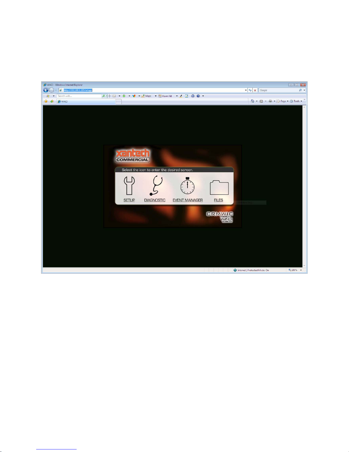
Admin Web Pages
Admin web pages include setup and diagnostic options, and may be accessed at:
http://[IP Address or Host Name]/setup/
From this web page, you may click on:
• SETUP - for firmware version, date/time setting, network settings, and network security
settings.
• DIAGNOSTIC – serial port configuration settings, firmware upgrade instructions, logs,
options, and other diagnostic tools for using and/or monitoring CRM-WIC hardware.
• EVENT MANAGER {see separate section, The Event Manager, page 30} - powerful non-
programming tool to automate CRM-WIC tasks.
• FILES - opens an ftp connection to the CRM-WIC.
20
Page 21
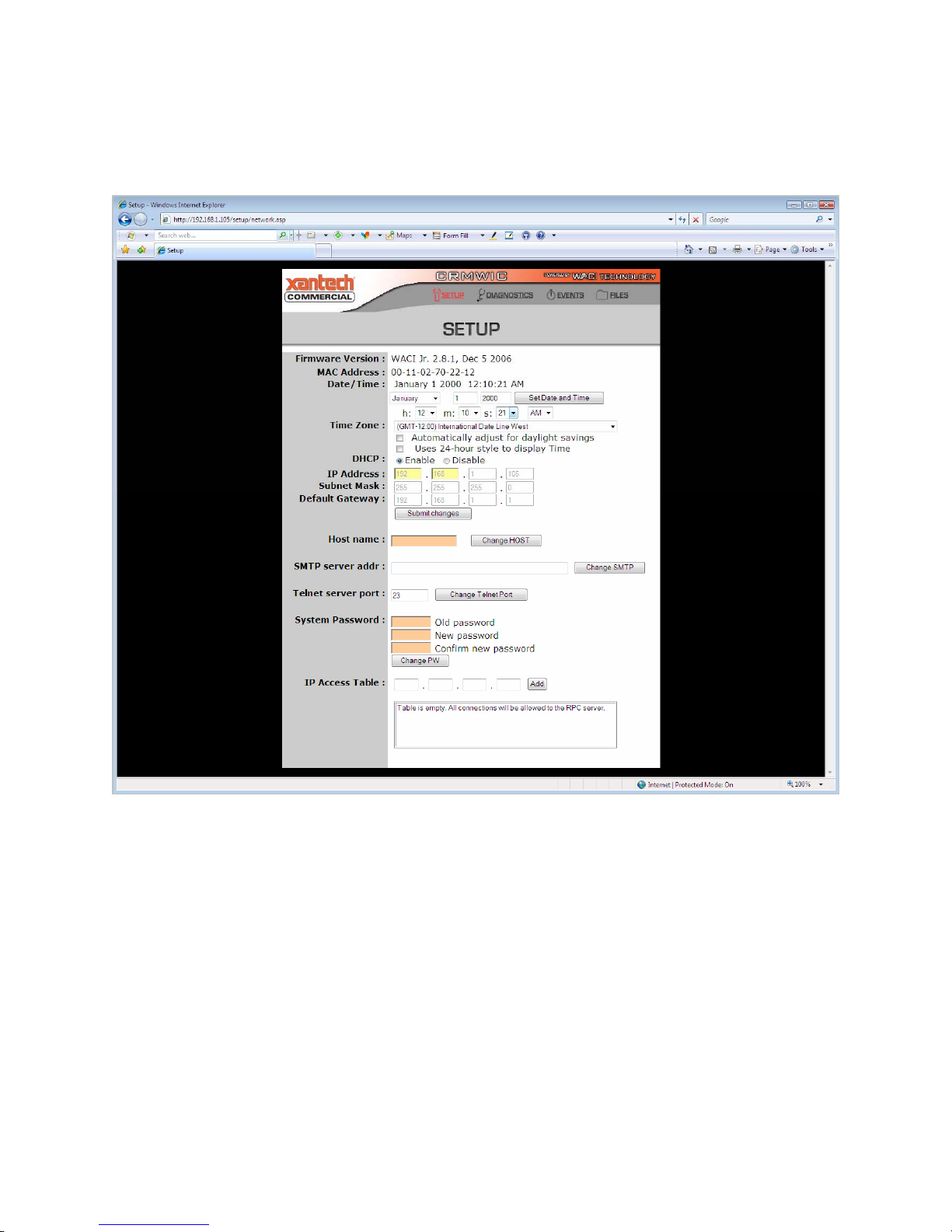
Setup
This web page allows you to set several administrative options. Many of these options are also available
from the Boot Menu.
Firmware Version
The firmware version installed on the CRM-WIC is displayed.
Date / Time
The current date and time is displayed. You may also set the date and time using the pulldown menus.
21
Page 22

Network Settings
If DHCP is enabled for the CRM-WIC, the IP Address, Subnet Mask, and Default Gateway are
automatically assigned, and the values will be grey and uneditable.
If the DHCP is disabled, the values for IP Address, Subnet Mask, and Default Gateway will be black and
editable.
Host Name
By setting the host name, your CRM-WIC 's web server may be accessed at
http://[Host Name]/
Similarly, the FTP server may be reached at
ftp://[Host Name]/
System Password
The password allows you to access the Admin Web Pages and FTP servers.
IP Access Table
When specified, your CRM-WIC will only accept network requests from computers with these IP
addresses.
22
Page 23
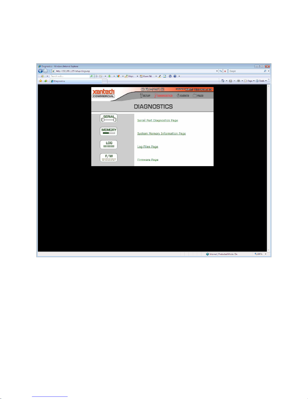
Diagnostics
Four of the Diagnostics described in this section (Serial, Memory, Log, and F/W) are available for the
CRM-WIC:
23
Page 24
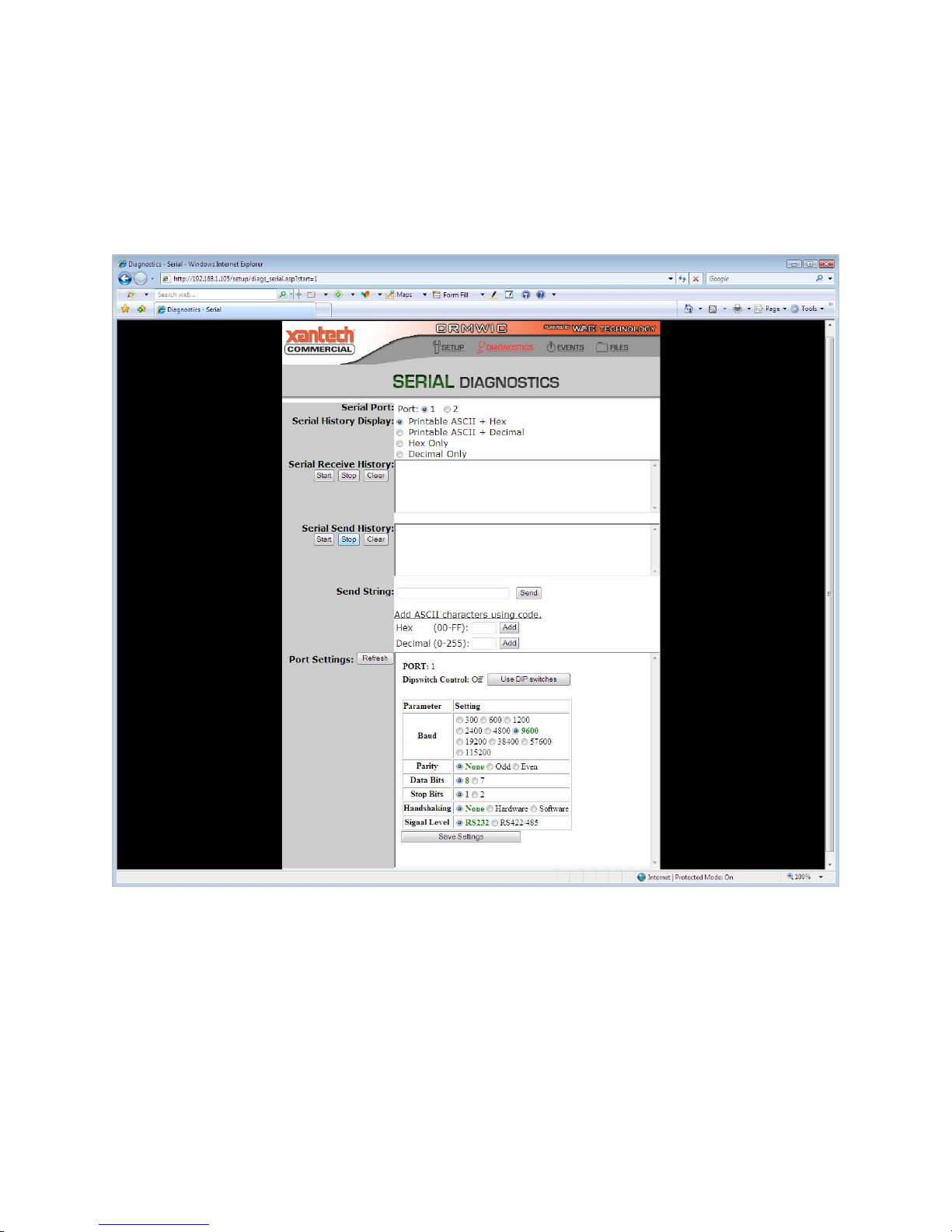
SERIAL: Serial Port Diagnostics
The serial port diagnostics are available for the CRM-WIC From this web page, you may access three
diagnostics for the serial ports.
Serial Send & Receive Histories
First, you may monitor the send and receive histories from either serial port.
The serial send and receive histories logs the bytes being output or input through the ports. First, select
which port to log (1 or 2), and then specify the display. The bytes passing through the port may be
displayed as printable ASCII characters, hex values, or decimal values.
If you select ASCII characters, you must also choose how you wish to view non-printable characters. The
non-printable characters are denoted by boldface type and "<" and ">" parentheses. For example, an
ASCII "space" character, which is non-printable, may be displayed as decimal value <32> or hex value
<20>.
24
Page 25

Send String
The second diagnostic allows you to send a byte stream through the port specified at the top of the page.
The byte stream you wish to send must be a URL-encoded send string:
To send a URL-encoded string, follow these three rules for encoding:
1. Enter your byte values as a string of printable ASCII characters and hex values. Spaces and
returns, for example, are non-printable characters and MUST be converted to hex.
2. Any hex value in the send string must be preceded by a "%" symbol.
3. The URL-encoded string does NOT accept decimal values, so if you only know the decimal
value of a byte, you MUST either convert it to a printable ASCII characters or the hex
equivalents.
For example, the decimal byte stream "103 111 111 100 32 100 111 103" is equivalent to the hex byte
stream "67 6F 6F 64 20 64 6F 67". It is also equivalent to the ASCII string "good dog". However, to
send the string to the serial port, you must use a combination of printable ASCII characters and hex
values only. Therefore, you may send the string as "good%20dog" or "good%20%64%6F%67", but not
"good dog" (contains a space, which is a non-printable character) or "good%32dog" (where "32" is a
decimal value). (You do not need to use quotes in the Send String text box.)
For your convenience, if you forget URL-encoding rules 2 and 3 above, you may add hex or decimal
values using the hex and decimal fields just below the Send String text box. Adding a hex number to
your Send String with the tool simply places the "%" prefix in front of the value you enter, with no
conversions. Adding a decimal number first converts the decimal number to the hex equivalent and
correctly places the "%" prefix in front of it within the send string.
If the Send History log has been started, the send string should appear in that display once the "Send"
button is pressed.
25
Page 26
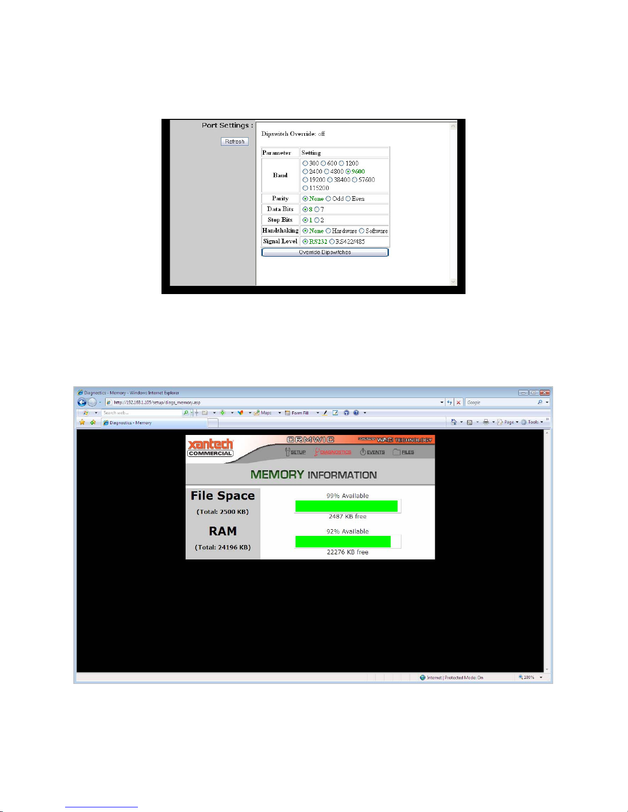
Serial Settings - Dipswitch Override
The final Serial diagnostic allows you to override the dipswitch settings for the port specified at the top of
the page:
These are standard settings for serial applications: Baud, Parity, Data Bits, Stop Bits, and Handshaking.
You may also choose whether to use RS-232 or RS-422/285 signal levels.
MEMORY: System Memory Information
System memory information is available for the CRM-WIC.
File space reflects the hard disk space available for custom web pages.
RAM reflects the status of the system memory.
26
Page 27

LOG: Log Files
Log files for the CRM-WIC servers are available for the CRM-WIC. An admin may review or clear
(reset) the logs from this page:
RPC Server Info
Displays the build date and version number of the RPC server. Also displays all tokens and methods
available from the server.
RPC Server Commands
Logs all HTTP Post calls to the server. Active X calls are not logged.
FTP Server Connections & Commands
Logs the FTP activity on the CRM-WIC.
Web Server
Logs the HTTP activity on the CRM-WIC's web server.
27
Page 28

F/W: Firmware
The Firmware page on the CRM-WIC will walk you through a CRM-WIC firmware update:
First, you will be prompted for the firmware files. Firmware upgrade files will have either the extension
.AFW for operating system upgrades, or .ABT for bootstrap loader upgrades.
Once your upgrade file has been located, the web page will tell you the tftp command line you will need
to execute to upload the file into your CRM-WIC. It will look something like:
tftp -i [IP Address] put [Filename with Full Path]
If ActiveX is enabled for your web browser, you may also request that the CRM-WIC create a batch file
CRM-WICload.bat that will execute this command. The batch file will be placed at the root of your
local drive.
To actually upload the file, click the "Ready to Download Firmware" button. The blue Status LED will
turn OFF, and all the Serial LEDs for both ports will be on. You will now need to upload the OS or boot
file using a tfpt client.
To use the default Windows tftp client, open a Command Line (or DOS Shell) window and execute the
tftp command shown on your web page OR simply execute the batch file. Alternatively, you may doubleclick on the batch file.
While the file is uploading, the serial LEDs will blink one at a time. Once the file is uploaded, the CRMWIC will reset, and you will be able to access the CRM-WIC’s web pages again.
Two important notes:
• You will not be able use the CRM-WIC for anything else while it is in the firmware upgrade
mode.
• You may only update one firmware file at a time. If you wish to update both the boot-strap
loader and firmware, you will need to completely upload one first, then repeat the entire
process for the other.
28
Page 29

Events (See section: The Event Manager)
Details of the Event Manager are described in the section, The Event Manager.
Files
This link will simply take you to the CRM-WIC's ftp server:
ftp://[IP Address or Host Name]/
Any custom web pages uploaded to the /wwwpub directory may be viewed at:
http://[IP Address or Host Name]/
29
Page 30

The Event Manager
The Event Manager is a feature of the CRM-WIC that allows you to program the CRM-WIC to perform
operations autonomously. With the Event Manager, you can associate different hardware or software
events with actions to be performed directly on the CRM-WIC. There is then no need to continuously
control the CRM-WIC using some client side software. Client side software can then be used to simply
check the CRM-WIC’s status.
Overview of Events, Actions, & Variables
In the simplest terms, when certain conditions in hardware or variables are met, the CRM-WIC may be
programmed to automatically perform specified tasks. To put this into the context of EVENTS,
ACTIONS, and VARIABLES:
• An EVENT is triggered when conditions in hardware reaches a user-defined state, or when a
value of a user-defined VARIABLE matches a user-defined constant.
• Once triggered, the EVENT can fire one or more ACTIONS.
• The conditions in hardware are typically read from one of the ports or the internal clock.
• Under many circumstances, user-defined states and constants can be written as expressions.
30
Page 31

The Event Manager Web Page
The Event Manager page may be accessed by clicking on "Events" at the top of any page. This page is
organized by events, actions, and variables.
Note that actions are always associated with its event. Selecting an event will highlight the event and
display all its associated actions.
Events, actions, and variables may be added, edited, and deleted from this page.
In addition, you may "Clone" (duplicate) an event with or without its associated actions.
31
Page 32

Events
Creating and Editing Events
Selecting the "Add event" button from the Event Manager page will create a new event, while selecting
the "Edit" button above the Event list will allow you to edit whichever event is highlighted.
You will be prompted for the name of the event, the type of event, and any options associated with the
event, as described in the next two sections.
Types of Events
As mentioned earlier, events are triggered when a condition is met in the hardware or for a variable. The
options for triggering an event depend on its type. The system recognizes the following types of events:
Clock
A Clock Event is triggered at a specified time of day on a calendar. Options include the start date and
time, as well as the one-time, daily, weekly, monthly, or yearly recurrence.
Timer
The timer operates by counting down from a value specified by hours:minutes:seconds. When the timer
"runs out", the Timer Event is triggered, and the timer is restarted at the specified value.
32
Page 33

While Clock Events allow you to schedule recurring tasks based on fixed, regular calendar periods (daily,
weekly, etc,), Timer Events allow you to schedule recurring tasks based on user-defined time periods.
For example, a Timer Event may be triggered every 27 seconds or 36 hours.
Variable
A Variable Event is triggered when the value of a variable matches a constant or expression.
Serial
Serial Events are triggered when the INPUT value at a specified port matches a constant or expression.
Other Event Options
Execute Actions Concurrently
When the "Execute actions concurrently" check box is CHECKED, all the actions associated with the
event will be executed concurrently at the time the event is triggered.
If this check box is UNCHECKED when the event is triggered, its actions will be executed sequentially,
one at a time, and in the order displayed on the Event Manager web page.
Expression
When the "(expression)" check box is CHECKED, the value specified in the "Trigger value" text box will
be parsed as an expression.
If the "(expression)" check box is UNCHECKED, the value specified in the "Trigger value" text box will
be considered a constant.
Trigger Value
This text box is used for events that are triggered by matches on a user-defined constant or expression.
Like variables, constants may be strings, numbers, schedules, or ranges.
To trigger an event using an expression, the user-specified value in the text box must be a Boolean
expression. When this Boolean expression resolves to TRUE, the event is triggered.
33
Page 34

Actions
Creating and Editing Actions
Actions are the tasks performed when an event is triggered, so they are always associated and displayed
with their events.
Actions may be created from the main Event Manager web page by first selecting an event, highlighting
it, and then selecting the "Add action" button.
Similarly, to edit an action, first select an event, and then select the associated action. When the desired
event and action are both highlighted, the "Edit" button above the list of Actions may be selected. From
the "edit action" page, you will have several options based on the type of Action.
Types of Actions
Variable
A Variable Action allows you to change the value of a variable once an event is triggered. Options that
must be defined for the Variable Action are the Output Variable and the Output Value.
The Output Value may be set to a constant, such as Hello or 5, or an expression, such as Counter+1.
If the "(expression)" check box is UNCHECKED, the specified value will be interpreted as a constant of
the same type as the variable.
34
Page 35

If the "(expression)" check box is CHECKED, the Output Variable will be assigned the value calculated
for the specified expression in the Output Value text box. The interpretation and calculation of
expressions are detailed in the Expressions section.
Serial
A Serial Action allows you to send an Output Value to a specified port. If the "(expression)" check box is
UNCHECKED, the value in the Output Value text box will be sent as a string to the specified port.
If the "(expression)" check box is CHECKED, the expression in the Output Value text box will first be
interpreted as described in the Expressions section, and the resulting string value will then be sent to the
specified port.
Event
Triggering an event can fire actions that trigger or cancel other events. An Event Action allows you to
specify the Events to "execute" or "cancel". Executing an event means that if the event is not already
triggered at the time the Event Action is called, the event will then be triggered, and any associated
actions will be fired. Canceling an event will stop the running of any actions associated with the event,
then untrigger the event.
NOTE: When an event is triggered, it remains triggered until all actions have been completed. Once the
actions are complete, the trigger flag is reset.
Action Timing Options
Actions may be:
• Infinite - execute the forever, or until another Action cancels the Event. Two notes: first,
checking the "Infinite" checkbox will override the "Execute" number of times field. Second,
the associated event will remain triggered unless another Action cancels the Event.
• Executed a particular number of times. Actions may be specified to execute as many as 2
times. This field is not used if the "Infinite" check box is CHECKED.
• Delayed by as many as 2
milliseconds. If the action is repeated any number of times, this delay only applies to the
first run.
• Repeated every N seconds, where N can be a maximum of 2
real number, as opposed to an integer, e.g. 2.5 for 2500 milliseconds. N applies to the time
period before the second and all subsequent runs.
28
seconds. The value can be a real number, e.g. 2.5 for 2500
28
seconds. The value can be a
31
Variables
Variables are created independently of events or actions, and any variable may be used in any event or
action. However, a variable may not be deleted until it is cleared from all the events or actions that use it.
35
Page 36

Creating and Editing Variables
Variables may be created from the main Event Manager web page by selecting the "Add variable" button.
To edit an existing variable, first select it so that it is highlighted, then select the "Edit" button above the
list of variables. The "edit variable" screen allows you to specify options and values for variable.
Some options for variables will differ by the type of variable. The options common to all variables are
Persistence, Default Value, and Current Value.
Persistence
When the Persistence flag is set, the Current Value of the variable will be stored to permanent storage
whenever it is changed. This value will persist through a system reset or power failure, so the Default
Value is not used when the "Persist" check box is CHECKED.
The storage of the Current Value does take some time, since it is stored into flash. Therefore, if a variable
is changed often, such as a counter, the CRM-WIC will perform more efficiently if you set a Default
Value, and UNCHECK the "Persist" check box.
Default Value
The Default Value is copied to the Current Value whenever the system starts up. The start-up typically
occurs from a system reset or a power failure. If a variable has the persistent flag set, the Default Value is
not used.
36
Page 37

Current Value
The Current Value is the working value of the variable. It is the value accessed in all Event and Action
expressions. In addition, Variable Actions [[see page]] send their outputs to the Current Value.
The Current Value is set to the Default Value during system start-up, if the Persistent flag is not set.
Types of Variables
Number
A Number Variable can have an integer value between -231 and +231-1.
Schedule
A Schedule Variable can have a time value, specified by [hour]:[minute]:[second] [AM/PM]
fields.
String
A String Variable can be a Unicode string up to 128 characters in length.
Range
A Range Variable can be specified to a range of values between a minimum and maximum value. Each
value can be a number between -2
31
and +231-1. The maximum value should be greater than the minimum.
Range Variables have one other parameter, which is calculated from the minimum and maximum values.
The de-bounce value, displayed after the maximum value, is used to provide a small measure of
hysteresis to prevent flutter.
37
Page 38

Expressions
Trigger Values for Events and Output Values for Actions may be written as expressions (instead of
constant values) by checking the "(expression)" flag. Evaluating expressions is described in this section.
Interpreting Values as Expressions
If the "(expression)" option is UNCHECKED, the trigger and output values are treated as simple strings,
and no quotation marks are needed. (NOTE: Variable Events and Actions automatically interpret the
value based on its variable type [[see types]].)
On the other hand, if the "(expression)" option is CHECKED, the CRM-WIC will treat the values as
expressions and evaluate them before matching on a trigger or sending an output.
In an expression, any string values must now be in quotes. Otherwise, the token will treated as an
identifier. For example:
• "Hello" (in quotes) is a string value in the expression.
• Hello (without quotes) is an identifier for a variable.
Special characters inside string values (inside quotes) must be escaped
Evaluation of Expressions
Expressions are evaluated strictly left-to-right, and order of operations is NOT supported. However,
parentheses may be used to prioritize the execution of the expression.
In addition, the type of operation (string, integer, etc) and the final value of the expression is determined
by the first token. If a string cannot be resolved to an integer during an integer operation, it takes on the
value of 0 (zero).
Some examples:
This expression... ... resolves to this
value.
3+4*5 35
3+(4*5) 23
"Hello"*3 "HelloHelloHello"
"Hello"+3 "Hello3"
Hello+3 7
3+"6" 9
3+"Hello" 3
Notes
No order of operations.
Priority is indicated by parentheses.
* is a string operator here.
The number 3 becomes part of the "Hello" string
because the string comes first.
Assuming Hello is a variable holding a value of 4, a
number.
The string "6" is valued as 6, a number, because 3 is
a number.
The string is treated as 0 because "Hello" has no
integer interpretation.
38
Page 39

Operators
The operators that are supported are:
• Arithmetic operations: +, -, *, /
• Logical comparison operators: ==, != , <, >
• Logical operators: &&, ||, !
• Bitwise operators: &, | , ~
• Range operator: in
Addition/Plus (+) Operator
The ‘+’ operator is used to append one string to another, or to add two integer values together.
Adding a number to a string will produce a string with the number (as text) appended to the end. Adding
a string to a number results in just the number (unless the string contains a value that can be converted to
a number).
For example:
This expression... ... resolves to this value.
3+4 7
"Hello"+" "+"There" "Hello There"
"Hello"+3 "Hello3"
3+"Hello" 3
3+"6" 9
Subtraction/Minus (-) Operator
The subtraction operator works with both numerical values and strings values. Use this operator with
strings to remove a substring from a source string, or use this operator to subtract two integer values.
For example:
This expression... ... resolves to this value.
6-2 4
"Hello"-"ll" "Heo"
"Hello"-"ll" "Heo"
10-"3" 7
39
Page 40

Multiplication/Times (*) Operator
This operator multiplies two numbers, or can be used for creating a string with a repeating value. The
numbers and strings can be either variables or literals.
For example:
This expression... ... resolves to this value.
4*5 20
"Hello"*3 "HelloHelloHello"
3*"Hello" 0
Division/Divide (/) Operator
The divide operator is valid only for numerical values and variables. Use this operator to divide one
numerical value by another. The resultant type is an integer value. [[what is error]]
For example:
This expression... ... resolves to this value.
10/3 3
10/2 5
Equal Comparison (==) Operator
The equal comparison operator will compare two tokens, which can be strings or integers. The
expression will return 1 if the two tokens are equivalent, and 0 if they are not.
For example, assuming MyNumber has an integer value of 4, and MyName has a string value of
"John":
This expression... ... resolves to this value.
MyNumber==4 1
MyNumber=="4" 1
MyNumber==5 0
MyName=="John" 1
0=="John" 1
40
Page 41

Not-Equal Comparison (!=) Operator
The not-equal comparison operator will compare two tokens, which can be strings or integers. Exactly
opposite to the equal comparison operator, the expression will return 0 if the two tokens are equivalent,
and 1 if they are NOT equal.
For example, assuming MyNumber has an integer value of 4, and MyName has a string value of
"John":
This expression... ... resolves to this value.
MyNumber!=4 0
MyNumber!="4" 0
MyNumber!=5 1
MyName!="John" 0
0!="John" 0
Greater-Than Comparison (>) Operator
The greater-than comparison operator will compare two tokens, which can be integers. The expression
will return 1 if the first token has a larger value than the second, and 0 if the second value is larger or
equal.
For example, assuming MyNumber has an integer value of 4:
This expression... ... resolves to this value.
MyNumber>5 0
MyNumber>4 0
MyNumber>3 1
Less Than Comparison (<) Operator
The less-than comparison operator will compare two tokens, which can be integers or strings. The
expression will return 1 if the first token has a smaller value than the second, and 0 if the second value is
smaller or equal.
For example, assuming MyNumber has an integer value of 4:
This expression... ... resolves to this value.
MyNumber<5 1
MyNumber<4 0
MyNumber<3 0
Logical-And (&&) Operator
Assume you have two Boolean expressions, Expression1 and Expression2, each returning true
(1) or false (0). The logical-and operator determines the true or false state of the complex expression
Expression1&&Expression2 using the rules applying to a traditional logical AND statement:
41
Page 42

If Expression1
is...
True (1) True (1) True (1)
True (1) False (0) False (0)
False (0) True (1) False (0)
False (0) False (0) False (0)
and
Expression2
is...
Expression1&&Expression2
resolves to...
In other words:
This expression... ... resolves to this value.
(3==3)&&(4==4) 1
1&&(4==5) 0
0&&(4==4) 0
(3==6)&&0 0
Logical-Or (||) Operator
Assume you have two Boolean expressions, Expression1 and Expression2, each returning true
(1) or false (0). The logical-or operator determines the true or false state of the complex expression
Expression1||Expression2 using the rules applying to a traditional logical OR statement:
If Expression1
is...
True (1) True (1) True (1)
True (1) False (0) True (1)
False (0) True (1) True (1)
False (0) False (0) False (0)
and
Expression2
is...
Expression1&&Expression2
resolves to...
In other words:
This expression... ... resolves to this value.
(3==3)||(4==4) 1
1||(4==5) 1
0||(4==4) 1
(3==5)||0 0
Logical-Not (!) Operator
The logical-not is a prefix operator that "negates" the Boolean expression that follows it. In other words,
if Expression1 returns true (1), !Expression1 returns false (0).
For example:
42
Page 43

This expression... ... resolves to this value.
!0 1
!(4==3) 1
!("Hello"=="Hello") 0
43
Page 44

Bitwise-And (&) Operator
The bitwise-and operator performs the logical AND operation bit by bit between two integers. This is
better understood by looking at the example of 12&10. The binary value of 12 is 1100, and the binary
value of 10 is 1010. 12&10 is computed by performing an AND between each of the corresponding
four bits:
12: 1 1 0 0
10: 1 0 1 0
12&10: 1 0 0 0
Therefore: 12&10 = (Hex) 1000 = (Decimal) 8
Bitwise-Or (|) Operator
The bitwise-or operator performs the logical AND operation bit by bit between two integers. This is
better understood by looking at the example of 12|10. The binary value of 12 is 1100, and the binary
value of 10 is 1010. 12I10 is computed by performing an OR between each of the corresponding four
bits:
12: 1 1 0 0
10: 1 0 1 0
12|10: 1 1 1 0
Therefore: 12|10= (Hex) 1110 = (Decimal) 14
Bitwise-Not (~) Operator
The bitwise-not prefix operator performs the logical NOT to each bit od an integer. This is better
understood by looking at the example of ~5. The binary value of 5 is 101. ~5 is computed by
performing a NOT on each of the three bits:
5: 1 0 1
~5: 0 1 0
Therefore: ~5 = (Hex) 010 = (Decimal) 2
44
Page 45

Range (in) Operator
The ‘in’ operator compares a numerical value or variable against a range variable. The resultant type is an
integer value of either 0 or 1. If the value is within the range, 1 is returned; otherwise, 0 is returned.
For example, assume Count has a value of 15, Range10 has a value of 1 to 10, and Range20 has a value
of 1 to 20
This expression... ... resolves to this value.
Count in Range10 0
Count in Range20 1
Escaping Special Characters
Escape characters can be placed anywhere in an expression, though the expression will fail to evaluate if
the escape character causes an invalid expression. The escape character should be placed within quotes
when defining an expression, e.g. "\m". Quotes are not needed if the "(expression)" check box is
UNCHECKED for the event or action. Valid escape codes are:
Code Name Description
\a bell alert Character code: 0x07
\b backspace Character code: 0x08
\d Date Represents the date as a string:
MM/DD/YYYY
\f Form feed Character code: 0x0C
\g Trigger data Data that triggered the current Event
\m Time Time that the current event was triggered
at: HH:MM:SS in 24hr format
\n New line or linefeed Character code: 0x0D
\o Origin that triggered
event
\r Carriage return Character code: 0x0A
\t Horizontal tab Character code: 0x09
\v Vertical tab Character code: 0x0B
\' Single quote Character code: 0x27
\" Double quote Character code: 0x22
\\ Backslash Character code: 0x5C
\? Question mark this is needed, because wild cards will be
\* Asterisk Character code: 0x2A
Port number, variable name, etc. The
value depends on the type of event.
identified by * and ? within the string.
45
Page 46

Remote Procedure Calls
The CRM-WIC supports remote procedure calls (RPCs) for most web interfaces, including HTML, Flash
(.fla), and Active Server Pages (.asp). Methods are typically called using the HTTP Post syntax for
HTML and Flash, and Visual Basic scripting for Active Server Pages.
This RPC reference covers:
• RPC Server Logs
• Syntax for HTTP Post
• Fault Codes
• Flash Example
• Visual Basic Scripting
• Note on Error Checking
• Detailed List of All Methods
RPC Server Logs
As noted in Diagnostics web pages section, key information regarding the RPC server can be retrieved
from the Log Files web page. This information includes the RPC server version and a list of available
methods. The Log Files web page also allows you to enable logging for the RPC commands.
Syntax for HTTP Post
Call Tokens
Methods may be called using HTTP Post using the following call tokens:
• version - The RPC server version may be obtained through the Log pages in the Admin Web
Pages, but this token is entirely optional and may be safely omitted from the call.
• method - Name of the method to call.
• param[i] - Value for parameter #i, where i is an integer.
General format for a call using HTTP Post:
[version=[ RPC Server Version ]&]method=[ Method to Call
][¶m1=[ Value for Parameter 1 ]¶m2=[ Value for
Parameter 2 ]¶m3=[ Value for Parameter 3, etc...]]
See the detailed list of methods at the end of this reference for the method name and the values for
param1, param2, etc. These parameter values are denoted by the text "[in]" in the Syntax and
Parameters sections.
46
Page 47

Response Tokens
The response tokens are:
• status - 0 for Failure, 1 for Success
• faultCode - If status is 0 (failure). faultCode will be an integer representing a specific error
{Fault Codes, page 48}. This token is NOT returned if status is 1 (success).
• response[i] - Returned value #i, where i is an integer. If status is 0 (fail), the value for
response1 will be a string describing the failure, and the value for response2 will be a debug
string giving more information about the failure.
Returned values are strings, integers, or Booleans, depending on the method. See the detailed list of
methods at the end of this reference for details about the returned values for any given method. These
returned values are denoted by the text "[out, retval]" in the Syntax and Parameters sections.
The response to the HTTP Post will be a string in the format:
status=[ 0 or 1 ][&faultCode=[Fault Code]] [&response1=[ Value
for Response 1 ] &response2=[ Value for Response 2 ]
&response3=[ Value for Response 3, etc...]]
EXAMPLE #1: Serial_GetSettings
Let us look at the method Serial_GetSettings (defined on page 55). From the Syntax and
Parameter sections, we can tell that param1 is a long integer that specifies either serial port #1 or #2.
We can also see that response1 (retval, or return value) is a string describing the settings for the given
port.
Using the HTTP Post format, the call to obtain settings from serial port #2 is:
version=2.0&method=Serial_GetSettings¶m1=2
Since the version token is optional, this call may be simplified:
method=Serial_GetSettings¶m1=2
A sample response for this call:
status=1&response1=9600,8,ODD,2,1,SOFTWARE
Responses are not usually used in its raw string format. A web programmer will typically parse the
response before displaying or otherwise making use of the information received.
EXAMPLE #2: Net_GetSubnetMask
The call for the Net_GetSubnetMask method:
method=Net_GetSubnetMask
Sample response:
status=1&response1=255.255.255.0
47
Page 48

Fault Codes
Fault Code Fault Description
1 Function parameter out of range / item specified does not
exist
2 Timed out waiting for a mutex or shared resource
3 Memory allocation failure
4 Configuration does not support action (ie. setting a Digital
I/O output when it is configured as an input)
5 Failed to find entry in database (registry or FRAM)
6 Failed to store persistent database (registry or FRAM),
settings might not be saved
7 Some internal error occurred that does not fit another
category. Must use extended error information to
diagnose.
8 An expected file format was invalid
9 IR signal too strong, receiver is overloaded
10 IR signal too weak
11 Other IR capture error
Using Macromedia Flash
You may access all WACP RPCs using HTTP post. In Flash, you may accomplish this using LoadVars{}
and sendAndLoad(). An example for making these calls follows.
STEP 1: Pass CRM-WIC IP Address to Flash
To begin, you must pass the IP address of CRM-WIC to your Flash file. There is more than one way to
do this, but below, we describe one sample method using JavaScript. NOTE: In this script, the .html
and.swf files must reside on the CRM-WIC to determine the IP address.
First, at the top of the .html file in which you are embedding your flash file (here, the name of the file is
"MyCRM-WICShockWaveFlashFile.swf"), insert this bit of script:
<script type="text/javascript" language="JavaScript">
thispage = location.href;
URLarr = thispage.split("/");
theIP = URLarr[2];
theFILE = "MyCRM-WICShockWaveFlashFile.swf";
</script>
48
Page 49

Next, use this bit of script to embed the flash file in the desired area of the web page:
<script type="text/javascript" language="JavaScript">
document.write('<object id="CRM-WIC" classid="clsid:D27CDB6E-
AE6D-11cf-96B8-444553540000"
codebase="http://download.macromedia.com/pub/shockwave/cabs
/flash/swflash.cab#version=6,0,29,0" width="100%"
height="100%">');
document.write('<param name="movie" value="'+theFILE+'" />');
document.write('<param name="quality" value="high" />');
document.write('<param name="FlashVars"
value="callerID='+theIP+'" />');
document.write('<embed name="flashMovie" src="'+theFILE+'"
FlashVars="callerID='+theIP+'" quality="high"
pluginspage="http://www.macromedia.com/go/getflashplayer"
type="application/x-shockwave-flash" width="100%"
height="100%"></embed>');
document.write('</object>');
</script>
The IP Address may now be access from your Flash action scripts in the variable "callerID".
Step 2: Call RPC with HTTP Post
Once you have the IP address, you are able to access the RPC server. Load the method and it's
parameters into a LoadVars() object as shown below, then make the call with sendAndLoad().
// Get CRM-WIC IP
RPCServerIP = [callerID, or whatever you used to get the IP
address of the CRM-WIC];
// Initialize Call & Response Tokens
CRM-WIC_Call = new LoadVars()
CRM-WIC_Response = new LoadVars()
// Set up RPC method and parameters you desire to call.
// Note that these are all URL-encoded strings.
// You may assign values based on buttons, text fields,
constants, or whatever else is appropriate for your page.
CRM-WIC_Call.method = "[Desired RPC Method]";
CRM-WIC_Call.param1 = "[Parameter 1 for the Method]";
CRM-WIC_Call.param2 = "[Parameter 2 for the Method]";
CRM-WIC_Call.param3 = "[Parameter 3 for the Method]";
[etc.]
// Call the RPC using HTTP Post
CRM-WIC_Call.sendAndLoad("http://"+RPCServerIP"/RPC", CRM-
WIC_Response, POST);
49
Page 50

Step 3: Response Tokens
At this point, if you used the script template above, you may now examine, use, and/or display the
contents of:
CRM-WIC_Response.status
CRM-WIC_Response.faultCode
CRM-WIC_Response.response1
CRM-WIC_Response.response2
CRM-WIC_Response.response3
[etc.]
The response tokens, like methods and call tokens, are all in the form of URL-encoded strings.
Visual Basic Scripting
To access an RPC using Visual Basic, first create a CRM-WIC object of type "CRM-WIC.UserAPI.1".
Then, call the method with the object, specifying any parameters in parentheses. For example, this script
in an Active Server Page retrieves the IP address of the CRM-WIC and the settings for serial ports 1 and
2.
Dim CRM-WICUser
Dim strIP, strErr
Dim strPort1, strPort2
set CRM-WICUser = CreateObject("CRM-WIC.UserAPI.1")
strIP = CRM-WICUser.Net_GetIPAddress
if(strIP = "") then
strErr = CRM-WICUser.GetLastErrorString
end if
strPort1 = CRM-WICUser.Serial_GetSettings(1)
strPort2 = CRM-WICUser.Serial_GetSettings(2)
Some notes:
• Parameters and returned values are strings, integers, or Booleans, depending on the method.
• The above example includes error checking for Net_GetIPAddress. Methods will report
errors based on the type of its return value. Strings will return the null string, integers will
return -1, and Booleans will return FALSE.
• See the detailed list of methods at the end of this reference for details about the parameters
and return values for any given method. Parameter values are denoted by the text "[in]" in
the Syntax and Parameters sections. Similarly, the return value is denoted by the text
"[out, retval]".
• String values should be passed in as URL encoded values. Returned strings are also URL
encoded.
50
Page 51

Note on Error Checking
The HRESULT, referred to in the Syntax of each method, ALWAYS returns "S_OK", so it is not useful
in error checking.
Instead, use the error checking values described in the HTTP Post and Visual Basic above, and the Error
Information Methods below[[]] to perform meaningful error checks.
Errors are based on the type of a function’s out/retval value. On error, a string retval is returned
as a null string, an integer retval returns -1, and Booleans will return FALSE.
Error Information Methods
GetLastErrorCode ( )
Returns the fault code from the last failed method call.
Syntax
HRESULT GetLastErrorCode(
[out, retval] long* Code
);
Parameters
Code [out, retval] Integer representing fault code.
Remarks
The value of Code corresponds to faultCode of an HTTP Post response when status is 0 (failure).
See {Fault Codes, page 48} for a list of defined codes.
GetLastErrorString ( )
Returns the description of the error from the last failed method call.
Syntax
HRESULT GetLastErrorString(
[out, retval] BSTR* ErrorString
);
51
Page 52

Parameters
ErrorString [out, retval] String describing an error.
Remarks
ErrorString corresponds to response1 of an HTTP Post response when status is 0 (failure).
GetLastExtendedErrorString ( )
Returns an extended description of the error from the last failed method call.
Syntax
HRESULT GetLastExtendedErrorString(
[out, retval] BSTR* ExtErrorString
);
Parameters
ExtErrorString [out, retval] String giving more information about an error.
Remarks
Corresponds to response2 of an HTTP Post response when status is 0 (failure).
General Information Methods
AllState_Get ( )
Returns the entire hardware state
Syntax
HRESULT AllState_Get(
[out, retval] VARIANT* Array
);
Parameters
Array [out, retval] Array representing entire hardware state.
Remarks
The array is filled as follows. Each port value is separated from the next port value by a comma.
Element # Field Type Example
0 Date DATE
1 Serial Rcv Buffer
Count
BSTR "0,1092"
52
Page 53

Time_GetDate ( )
Returns current time and date on the device.
Syntax
HRESULT Time_GetDate(
[out, retval] DATE* Date
);
Parameters
Date [out, retval] DATE object.
Remarks
If the returned DATE object represents a date before 1900, the returned value will be negative, signifying an error.
The format is
[year],[month],[day],[hour],[minute],[second],[millisecond]"
February 10, 2003, 7:15PM would be represented as "2003,2,10,19,15,0,0".
Precision is provided to the second, so the millisecond value is ALWAYS "0".
Time_Sleep ( Milliseconds )
Generates a wait period using the specified number of milliseconds.
Syntax
HRESULT Time_Sleep(
[in] long Milliseconds,
[out, retval] VARIANT_BOOL* Success
);
Parameters
Milliseconds [in] The number of milliseconds to wait.
Success [out, retval] TRUE if the Milliseconds value is greater than or equal to 0 and less than or equal to 999999, and
FALSE if value is outside this range.
Remarks
The call to this function will not return until after the wait time has expired.
Net_GetIPAddress ( )
Returns the current IP address of the device.
Syntax
HRESULT Net_GetIPAddress(
[out, retval] BSTR* IP
);
Parameters
IP [out, retval] String containing the current IP address of the device, such as "10.0.1.3".
53
Page 54

Net_GetSubnetMask ( )
Returns the current subnet mask of the device.
Syntax
HRESULT Net_GetSubnetMask(
[out, retval] BSTR* SubnetMask
);
Parameters
SubnetMask [out, retval] String containing the current subnet mask of the device, such as "255.255.255.0".
54
Page 55

Serial Methods
Serial_GetSettings ( Port )
Returns the port settings for the specified serial port. Use the CRM-WIC DIP switches or Web interface to set these
parameters.
Syntax
HRESULT Serial_GetSettings(
[in] long Port,
[out, retval] BSTR* Settings
);
Parameters
Port [in] Port number for the serial port. Valid values are 1 and 2.
Settings [out, retval] Comma separated string representing the current port settings. On error, this parameter is returned as
Remarks
Valid values for the different settings are:
Baud: 300, 600, 1200, 2400, 4800, 9600, 19200, 38400, 57600, and 115200
Parity: ODD, EVEN, NONE
Stop Bits: 1, 2
Flow Control: HARDWARE, SOFTWARE, NONE
NULL or “”. The format of the string is: baud-rate, parity, stop-bits, RS422-flag, flow-control, e.g.
"9600,8,NONE,1,0,HARDWARE".
Serial_Send ( Port, Msg, MaxWaitMS )
Sends a string to the specified port.
Syntax
HRESULT Serial_Send(
[in] long Port,
[in] BSTR Msg,
[in] long MaxWaitMS,
[out, retval] long* NotSent
);
Parameters
Port [in] Port number for the serial port. Valid values are 1 and 2.
Msg [in] URL encoded string to be sent to the port.
MaxWaitMS [in] The number of milliseconds allowed to complete the sending of the serial data before timing out.
NotSent [out, retval] If an error occurred or the timeout expired, then this is the number of bytes not sent; otherwise, this value
is set to 0.
Remarks
The Msg parameter text should be passed in as a URL encoded string. To have a Nul character sent out the serial port, pass a
“%00” as part of the Msg string.
55
Page 56

Serial_Read ( Port )
Returns the contents of the serial read buffer for the specified serial port.
Syntax
HRESULT Serial_Read(
[in] long Port,
[out, retval] BSTR* Read
);
Parameters
Port [in] Port number for the serial port. Valid values are 1 and 2.
Read [out, retval] URL encoded string read from the specified port.
Remarks
The string returned by this method is in URL encoded format. Once the data is read from the buffer, the contents of the
serial read buffer are cleared.
Serial_ClearReadBuffer ( Port )
Clears the contents of the read buffer for the specified port.
Syntax
HRESULT Serial_ClearReadBuffer(
[in] long Port,
[out, retval] VARIANT_BOOL* Success
);
Parameters
Port [in] Port number for the serial port. Valid values are 1 and 2.
Success [out, retval] TRUE if the buffer was cleared, FALSE if buffer failed to clear.
Remarks
If you wish to read a specific response to a sent command, then make a call to this function just prior to calling Serial_Send.
Serial_ReadBufferCount ( Port )
Returns the number of characters in the read buffer for the specified port. The maximum number of characters stored by the
circular buffer is 4K.
Syntax
HRESULT Serial_ReadBufferCount(
[in] long Port,
[out, retval] long* Count
);
Parameters
Port [in] Port number for the serial port. Valid values are 1 and 2.
Count [out, retval] Number of characters currently in the receive buffer.
56
Page 57

Event Methods
Most of the Event methods use the Event’s ID to retrieve information about an Event. The Event’s ID is
set when an Event is created, and is unique to the Event. The ID is re-issued when the system is powered
up or the reset button is pressed.
The index number of the Event within the event list could change, depending on whether new Events are
added or existing Events are deleted.
GetEventByIdx ( Idx )
Returns the Event ID for a specified index number.
Syntax
HRESULT GetEventByIdx(
[in] long Idx,
[out, retval] long* EventId
);
Parameters
Idx [in] The index of the Event in the Event list
[out, retval] Event ID of the specified event.
EventId
Remarks
GetEventByIdx is normally used as part of a loop for getting the list of created events. Use GetEventCount to get the
number of Events. Use GetEventByIdx to get the ID of the next Event in the list. Then use the ID and the remaining
Event functions to retrieve the information you are interested in, e.g. Name, Type, Actions, etc.
The index numbers start at 0 and stop at Count-1, where Count is gotten with GetEventCount.
If -1 is returned, then index is out of range. If -2 is returned, then the Event represented by Idx is in the process of being
deleted.
GetEventByName ( Name )
Returns an Event ID for an event with a specified name.
Syntax
HRESULT GetEventByName(
[in] BSTR Name,
[out, retval] long* EventId
);
Parameters
Name [in] Name of the event to identify.
EventId [out, retval] Event ID of the specified event.
Remarks
The ID returned by GetEventByName is used by the Event functions to retrieve information about the named Event, e.g.
Name, Type, Actions, etc.
If -1 is returned, then the Event specified by Name doesn’t exist. If -2 is returned, then the Event represented by Name is
in the process of being deleted.
57
Page 58

GetEventIdxById ( EventId )
Returns the index into the Event list for an Event with a specified ID.
Syntax
HRESULT GetEventIdxById(
[in] long EventId,
[out, retval] long* Idx
);
Parameters
EventId [in] ID for the specified event.
Idx [out, retval] The index of the Event in the Event list.
Remarks
The index returned will be in the range 0 to Count-1, where Count is the value returned by GetEventCount.
-1 is returned if the Event with the specified ID is not found.
GetEventName ( EventId )
Returns the name of the Event with a specified ID.
Syntax
HRESULT GetEventName(
[in] long EventId,
[out, retval] BSTR* Name
);
Parameters
EventId [in] ID for the specified event.
Idx [out, retval] Name of the specified event.
GetEventType ( EventId )
Returns the type of the Event with a specified ID.
Syntax
HRESULT GetEventType(
[in] long EventId,
[out, retval] long* Type
);
Parameters
EventId [in] ID for the specified event.
Type [out, retval] Type of the specified event.
58
Page 59

Remarks
Type is returned as one of the following values:
Value Type
0 Unknown
1 Scheduled
2 Timer
3 Variable
4 Serial Input
5 Digital Input
6 A/D Input
GetEventOption ( EventId, OptionType )
Returns the value of a specified option for a specified event.
Syntax
HRESULT GetEventOption(
[in] long EventId,
[in] long OptionType,
[out, retval] long* OptionVal
);
Parameters
EventId [in] ID for the specified event.
OptionType [in] Type of option for the event.
OptionVal [out, retval] Value of the specified option for the event.
Remarks
Pass one of the following values into OptionType:
Value Option
1 Concurrent 0 – Event’s actions are executed
2 Expression 0 – The trigger value is a simple text
3 Disable 0 – The Event is enabled
OptionVal returned
serially
1 – Event’s actions are executed
concurrently
string
1 – The trigger value is an expression
1 – The Event is disabled
59
Page 60

GetEventConcurrent ( EventId )
GetEventConcurrent returns a value signifying whether an Event’s Actions should run concurrently or sequentially.
Syntax
HRESULT GetEventConcurrent(
[in] long EventId,
[out, retval] long* Concurrent
);
Parameters
EventId [in] ID for the specified event.
Concurrent [out, retval] 1 if actions should be executed concurrently, 0 if actions should be executed sequentially.
Remarks
When Actions are set to execute sequentially, the next Action in the list will not execute until the previous Action has
completely executed. So, if the first Action is set as one that executes an infinite number of times, the second Action will
never execute. Use the Up/Dn hyperlinks in the Event Manager Diagnostics screen’s Action list to change the order of the
Actions’ execution.
When Actions execute concurrently, the Event Manager determines the next Action to run by calculating its next run time.
The Event Manager uses the Action’s Delay and Repeat Every values to make this calculation. The Action with the earliest
next run time is run first. If two Actions have the same run time, the first Action in the Action list will be executed first.
This flag can also be obtained user GetEventOption.
GetEventSource ( EventId )
The port, variable, or clock that is monitored by the specified Event
Syntax
HRESULT GetEventSource(
[in] long EventId,
[out, retval] BSTR* Source
);
Parameters
EventId [in] ID for the specified event.
Source [out, retval] A string filled with the name of the variable, port, or clock.
Remarks
An Event monitors its Source for changes. When new data arrives, or the data changes, the Event is notified. The setting of
the Event’s match value determines whether the Event is signaled to execute on this change in data.
60
Page 61

GetEventMatch ( EventId )
Returns the expression to be evaluated or data to be compared when the Event is notified of a change in data
Syntax
HRESULT GetEventMatch(
[in] long EventId,
[out, retval] BSTR* Match
);
Parameters
EventId [in] ID for the specified event.
Match [out, retval] [???]]
Remarks
The Match value is either an expression or simple text value. How the match value is evaluated depends on the setting of
“Expression” in the Event Manager diagnostics.
If Match is an expression, then it is evaluated whenever there is a change in the Event’s source port, variable, etc. When the
expression evaluates to non-zero, the Event is scheduled to run.
When Match is not an expression, then the incoming data is compared against the Match value. If the Match matches the
data, then the Event is triggered to run.
GetEventSchClockType ( EventId )
Returns the type of schedule used by a time based Event.
Syntax
HRESULT GetEventSchClockType(
[in] long EventId,
[out, retval] long* ClockType
);
Parameters
EventId [in] ID for the specified event.
ClockType [out, retval] Is set to 1, if the Event is a scheduled event, and 0, if the Event is a timer based event.
Remarks
This function is valid only for Clock and Timer Events.
Use this function to determine if the Event is based on a simple timer, or is using a more complicated schedule.
61
Page 62

GetEventSchRecurType ( EventId )
Returns the type of schedule used by the specified Event.
Syntax
HRESULT GetEventSchRecurType(
[in] long EventId,
[out, retval] long* RecurType
);
Parameters
EventId [in] ID for the specified event.
RecurType [out, retval] Type of schedule to apply
Valid values for RecurType are:
Value Description
0 Once
1 Daily
2 Weekly
3 Monthly
4 Yearly
Remarks
This function is valid for Clock Events only.
GetEventSchMaskOrDay ( EventId )
When the Event is set as a weekly Event, then this function returns a mask that defines the days of the week. Yearly and
monthly Event schedule types use this value for specifying the day of the month.
Syntax
HRESULT GetEventSchMaskOrDay(
[in] long EventId,
[out, retval] long* MaskDay
);
62
Page 63

Parameters
EventId [in] ID for the specified event.
MaskDay [out, retval] Day of the month, or a mask of bits for the days of the week.
MaskDay values for weekly Events:
Bit Day
0 Sunday
1 Monday
2 Tuesday
3 Wednesday
4 Thursday
5 Friday
6 Saturday
Remarks
This function is valid only for Clock Events.
GetEventSchMonth ( EventId )
Returns the month value for the Event’s schedule.
Syntax
HRESULT GetEventSchMonth(
[in] long EventId,
[out, retval] long* Month
);
Parameters
EventId [in] ID for the specified event.
Month [out, retval] Integer representing the scheduled month of the year. Values will range from 1 to 12.
Remarks
This function is valid only for Clock Events.
The month value is only used for yearly event schedules.
63
Page 64

GetEventSchYear ( EventId )
Returns the year part of the Event’s schedule.
Syntax
HRESULT GetEventSchYear(
[in] long EventId,
[out, retval] long* Year
);
Parameters
EventId [in] ID for the specified event.
Year [out, retval] Integer representing the scheduled year (for example, "1984" or "2003").
Remarks
This function gets a value that is not used by the Event Manager.
GetEventSchRecurEveryN ( EventId )
Returns the “Recur every” value of the Event’s schedule.
Syntax
HRESULT GetEventSchRecurEveryN(
[in] long EventId,
[out, retval] long* EveryN
);
Parameters
EventId [in] ID for the specified event.
EveryN [out, retval] Repeat every N periods. The period depends on the type of schedule, e.g. Weekly, Monthly, etc.
Remarks
This function is valid only for Clock Events.
The “Recur Every” value (EveryN) is used by all the Event schedules, except one. The “Once” schedule does not repeat;
therefore, it does not need the EveryN value.
GetEventSchHour ( EventId )
Returns the hour that the Event is to be triggered.
Syntax
HRESULT GetEventSchHour(
[in] long EventId,
[out, retval] long* Hour
);
64
Page 65

Parameters
EventId [in] ID for the specified event.
Hour [out, retval] Integer representing the scheduled hour. Values range from 0 to 23.
Remarks
This function is valid only for Clock and Timer Events.
GetEventSchMinute ( EventId )
Returns the minute that the Event is to be triggered.
Syntax
HRESULT GetEventSchMinute(
[in] long EventId,
[out, retval] long* Minute
);
Parameters
EventId [in] ID for the specified event.
Minute [out, retval] Integer representing the scheduled minute. Values range from 0 to 59.
Remarks
This function is valid only for Clock and Timer Events.
GetEventSchSecond ( EventId )
Returns the second that the Event is to be triggered.
Syntax
HRESULT GetEventSchSecond(
[in] long EventId,
[out, retval] long* Second
);
Parameters
EventId [in] ID for the specified event.
Second [out, retval] Integer representing the scheduled second. Values range from 0 to 59.
Remarks
This function is valid only for Clock and Timer Events.
65
Page 66

SetEventById ( EventId, Name, Type, Concurrent, Source, Match )
Sets the basic information about an existing Event.
Syntax
HRESULT SetEventById(
[in] long EventId,
[in] BSTR Name,
[in] long Type,
[in] long Concurrent,
[in] BSTR Source,
[in] BSTR Match,
[out, retval] VARIANT_BOOL* Success
);
Parameters
EventId [in] ID for the specified event.
Name [in] Name of the specified event.
Type [in] Type of the Event, e.g. Serial.
Concurrent [in] Set to 1 to execute Actions concurrently, and 0 otherwise.
Source [in] Port, variable, etc. to be used for the source of the Event’s trigger.
Set Type to one of the following values:
Value Type
1 Scheduled
2 Timer
3 Variable
4 Serial Input
The value of Source depends on the type of Event.
Event Type Format String
Clock and Timer “RTC”
Variable Name of the Variable
Serial “Port%d”, where %d
represents a number
Match [in] Value to match to trigger the Event. If the Match value is an expression, then the expression will need to evaluate
Success [out, retval] TRUE if specified event was successfully set, FALSE if setting the event failed.
to 1 to cause the Event to trigger.
Remarks
Call this function to set up an Event. After making this call, a call to SetEventSchedule is required for all events of type
Clock or Timer.
A call to SetEventOption should also to be made to set or clear the expression flag for the Event’s match value.
SetEventByName ( Name, Type, Concurrent, Source, Match )
Using the name of an existing Event, this function sets the basic information about it.
66
Page 67

Syntax
HRESULT SetEventByName(
[in] BSTR Name,
[in] long Type,
[in] long Concurrent,
[in] BSTR Source,
[in] BSTR Match,
[out, retval] VARIANT_BOOL* Success
);
Parameters
Name [in] Name of the Event to set the information for.
Type [in] Type of Event, e.g. Clock
Concurrent [in] Set to 1 to execute Actions concurrently, and 0 otherwise
Source [in] Port, variable, etc. to be used for the source of the Event’s trigger The value of Source depends on the type of
Set Type to one of the following values:
Value Type
1 Scheduled
2 Timer
3 Variable
4 Serial Input
Event.
Event Type Format String
Clock and Timer “RTC”
Variable Name of the Variable
Serial “Port%d”, where %d
represents a number
Match [in] Value to match to trigger the Event. If the Match value is an expression, then the expression will need to evaluate
Success [out, retval] TRUE if specified event was successfully set, FALSE if setting the event failed.
to 1 to cause the Event to trigger.
Remarks
Call this function to set up an Event. After making this call, a call to SetEventSchedule is required for all events of type
Clock or Timer.
If Match is an expression, then a call to SetEventOption will also have to be made to set the expression flag for the Event.
SetEventOption ( EventId, OptionType, OptionVal )
Modify the option settings of a specified event.
Syntax
HRESULT SetEventOption(
[in] long EventId,
[in] long OptionType,
67
Page 68

[in] BSTR OptionVal,
[out, retval] VARIANT_BOOL* Success
);
Parameters
EventId [in] ID of the event to modify.
OptionType [in] Integer specifying which option to modify.
OptionVal [in] New value for the option.
Success [out, retval] TRUE if specified option was successfully set, FALSE if settin g the option failed.
Remarks
Pass one of the following values into OptionType:
Value Option
Set OptionVal to
1 Concurrent 0 – Event’s actions will execute serially
1 – Event’s actions will execute
concurrently
2 Expression 0 – The trigger value is a simple text
string
1 – The trigger value is an expression
3 Disable 0 – The Event is enabled
1 – The Event is disabled
If both SetEventSchedule and SetEventOption need to be called for an Event, then SetEventOption should be called before
SetEventSchedule.
68
Page 69

SetEventSchedule ( EventId, Recur, MaskOrDay, Month, Year, RecurEveryN,
Hour, Minute, Second )
Modify the schedule settings of a specified event.
Syntax
HRESULT SetEventSchedule(
[in] long EventId,
[in] long Recur,
[in] long MaskOrDay,
[in] long Month,
[in] long Year,
[in] long RecurEveryN,
[in] long Hour,
[in] long Minute,
[in] long Second,
[out, retval] VARIANT_BOOL* Success
);
Parameters
EventId [in] ID of the Event to modify the schedule of.
Recur [in] The recurrence pattern used for this schedule. .
Recur value Description
0 Once
1 Daily
2 Weekly
3 Monthly
4 Yearly
MaskOrDay [in] Mask of days or specific day of the month.
MaskDay values for weekly Events:
Bit Day
0 Sunday
1 Monday
2 Tuesday
3 Wednesday
4 Thursday
5 Friday
6 Saturday
Month [in] Month setting for the schedule. An integer between 1 and 12. This parameter is used only for yearly schedules.
Year [in] Year setting for the schedule. An integer such as "1984" or "2001"
RecurEveryN [in] Number of periods between successive triggers of the Event.
Hour [in] Hour setting for the schedule. An integer between 0 and 23.
Minute [in] Minute setting for the schedule. An integer between 0 and 60.
Second [in] Second setting for schedule. An integer between 0 and 60.
Success [out, retval] TRUE if schedule was successfully set, FALSE if setting the schedule failed.
69
Page 70

Remarks
This function is valid only for Clock and Timer Events.
If both SetEventSchedule and SetEventOption need to be called for an Event, then SetEventOption should be called before
SetEventSchedule.
CloneEventById ( EventId, CloneActions, NewName )
Clone (duplicate) an Event specified by its ID.
Syntax
HRESULT CloneEventById(
[in] long EventId,
[in] long CloneActions,
[in] BSTR NewName,
[out, retval] long* CloneID
);
Parameters
EventId [in] ID of the event to modify.
CloneActions [in] Duplicate all the Event’s Actions too.
NewName [in] Name of the new duplicate Event.
CloneID [out, retval] ID of the new duplicate Event.
Remarks
The name of the newly cloned Event will be set to “%s Copy”, where the %s is replaced by the name of the Event being
cloned. If a copy of the Event already exists, then an incrementing number is appended to the end, e.g. “MyEvent Copy3”.
AddEvent ( Name, Type, Concurrent, Source, Match )
Create a new event with the specified parameters.
Syntax
HRESULT AddEvent(
[in] BSTR Name,
[in] long Type,
[in] long Concurrent,
[in] BSTR Source,
[in] BSTR Match,
[out, retval] long* EventId
);
Parameters
Name [in] Name of the new event.
Type [in] Type of the Event, e.g. Serial. Pass one of the following values into Type:
Value Type of Event
1 Scheduled
2 Timer
3 Variable
4 Serial data
70
Page 71

Concurrent [in] Set to 1 to execute Actions concurrently, and 0 otherwise.
Source [in] Port, variable, etc. to be used for the source of the Event’s trigger. The value of Source depends on the type of
Event.
Event Type Format String
Clock and Timer “RTC”
Variable Name of the Variable
Serial “Port%d”, where %d
represents a number
Match [in] Value to match to trigger the Event.
EventId [out, retval] ID of the new event.
Remarks
Call this function to add a new Event. After making this call, a call to SetEventSchedule is required for all events of type
Clock or Timer.
A call to SetEventOption should also to be made using the newly returned EventId to set or clear the expression flag for the
Event’s match value.
DeleteEventById ( EventId )
Delete an Event specified by its ID.
Syntax
HRESULT DeleteEventById(
[in] long EventId,
[out, retval] VARIANT_BOOL* Success
);
Parameters
EventId [in] ID of the event to delete.
Success [out, retval] TRUE if the specified event was successfully deleted, FALSE if deleting the event failed.
Remarks
Calling this function deletes the Event as well as all Actions belonging to the Event.
DeleteEventByName ( Name )
Delete an Event specified by its name.
Syntax
HRESULT DeleteEventByName(
[in] BSTR Name,
[out, retval] VARIANT_BOOL* Success
);
Parameters
Name [in] Name of the event to delete.
Success [out, retval] TRUE if the specified event was successfully deleted, FALSE if deleting the event failed.
Remarks
Calling this function deletes the Event as well as all Actions belonging to the Event.
71
Page 72

SortEvents ( SortType, Direction )
Sorts the list of Events by the sort type and direction.
Syntax
HRESULT SortEvents(
[in] long SortType,
[in] long Direction,
[out, retval] VARIANT_BOOL* Success
);
Parameters
SortType [in] Type of sort to apply to the list.
Direction [in] Direction of the sort: ascending (1) or descending (0).
Success [out, retval] TRUE if the events are successfully sorted, FALSE if sorting the events failed.
Remarks
This function is not supported in the version 2.0 firmware.
GetEventCount ( )
Returns the total number of Events.
Syntax
HRESULT GetEventCount(
[out, retval] long* NumEvents
);
Parameters
NumEvents [out, retval] Total number of Events in the system.
Remarks
This function is used in conjunction with GetEventByIdx to get a list of the available Events.
72
Page 73

Action Methods
GetActionByIdx ( EventId, Idx )
Returns the Action ID for a specified Event ID and Action index number.
Syntax
HRESULT GetActionByIdx(
[in] long EventId,
[in] long Idx,
[out, retval] long* ActionId
);
Parameters
EventId [in] ID of the Event that contains the Action.
Idx [in] Index number for the Action.
ActionId [out, retval] Returned ID of the specified Action.
Remarks
Use this function to get the list of Actions associated with a particular Event. Each Event can contain up to 16 Actions.
GetActionByName ( EventId, Name )
Returns the Action ID for a specified Event ID and Action name.
Syntax
HRESULT GetActionByName(
[in] long EventId,
[in] BSTR Name,
[out, retval] long* ActionId
);
Parameters
EventId [in] ID of specified event.
Name [in] Name of the Action
ActionId [out, retval] Action ID of the specified Action.
Remarks
The name comparison is case sensitive, and requires an exact match. Wild cards are not supported.
73
Page 74

MoveActionByIdx ( EventId, Idx, Where )
Changes the order of execution for the Actions under the specified Event.
Syntax
HRESULT MoveActionByIdx(
[in] long EventId,
[in] long Idx,
[in] long Where,
[out, retval] VARIANT_BOOL* Success
);
Parameters
EventId [in] ID of specified event.
Idx [in] Index number for the Action of interest
Where [in] Direction to move the Action in the execution order. To move the Action up (execute earlier) pass 0. To move it
Success [out, retval] TRUE if the events are successfully sorted, FALSE if sorting the events failed.
down, pass 1.
Remarks
If Where == 0, and the Action is already at the top of the execution list (Idx == 0), then the function returns an error.
Similarly, if Where == 1 and the Action is at the bottom of the list, then an error is returned.
GetActionName ( ActionId )
Returns the name of an Action, specified by its ID.
Syntax
HRESULT GetActionName(
[in] long ActionId,
[out, retval] BSTR* Name
);
Parameters
ActionId [in] ID for specified action.
Name [out, retval] Name of the specified Action.
GetActionType ( ActionId )
Returns the type of an Action, specified by its ID.
Syntax
HRESULT GetActionType(
[in] long ActionId,
[out, retval] long* Type
);
Parameters
ActionId [in] ID for specified action.
Type [out, retval] Type of the specified action.
74
Page 75

Remarks
Action types that the CRM-WIC supports, depends on the device’s hardware capabilities. Type values are:
Value Action Type Supported on
1 Set a Variable’s value CRM-WIC
2 Send serial data CRM-WIC
5 Trigger another Event CRM-WIC
GetActionOption ( ActionId, OptionType )
Returns the option for an Action, specified by its ID and the option type.
Syntax
HRESULT GetActionOption(
[in] long ActionId,
[in] long OptionType,
[out, retval] long* OptionVal
);
Parameters
ActionId [in] ID for specified action.
OptionType [in] Type of option to examine.
OptionVal [out, retval] Value of the specified option.
Remarks
Two options are supported for Actions:
Value Description
1 Expression 0: output is a simple string
2 Disable 0: Action is enabled
Returned OptionVal
1: output is an expression
1: Action is disabled
75
Page 76

GetActionDelay ( ActionId )
Returns the “Delay before start” value for the specified Action.
Syntax
HRESULT GetActionDelay(
[in] long ActionId,
[out, retval] double* Delay
);
Parameters
ActionId [in] ID of the action to examine.
Delay [out, retval] Number of seconds to delay. A millisecond is represented as 0.001 seconds.
Remarks
For Actions that execute concurrently and for the first Action in the execution list, the value returned by this function is the
number of seconds that the Event Manager will wait after the owning Event has been triggered before executing the Action.
For Actions that execute serially, the value is the amount of time to wait after the previous action completed.
GetActionDutyCycle ( ActionId )
Returns the number of seconds to wait between successive executions of an Action.
Syntax
HRESULT GetActionDutyCycle(
[in] long ActionId,
[out, retval] double* Duty Cycle
);
Parameters
ActionId [in] ID of the action to examine.
DutyCycle [out, retval] Number of seconds between successive executions.
Remarks
The DutyCycle returned is also known as the period of the Action. A serial Action with a DutyCycle of 1 second will
send the output string out the serial port once every second.
GetActionStopAfter ( ActionId )
Returns the number of times to repeat the Action
Syntax
HRESULT GetActionStopAfter(
[in] long ActionId,
[out, retval] long* StopAfter
);
76
Page 77

Parameters
ActionId [in] ID of the action to examine.
StopAfter [out, retval] The number of times to execute the Action
Remarks
If -1 is returned in StopAfter, then the Action will execute continuously until the owning Event is specifically canceled
by an Action of type “Event”.
GetActionPort ( ActionId )
Returns the destination port of the Action specified by ActionId
Syntax
HRESULT GetActionPort(
[in] long ActionId,
[out, retval] BTSR* Port
);
Parameters
ActionId [in] ID of the action to examine.
Port [out, retval] Port to output to
Remarks
The value of Port represents where the Action is going to send its output. For variable Actions, the Port value is the
name of the Variable. Actions that execute or cancel an Event, the Port value is the name of the Event. In all other cases,
Port is the name of the port of the associated device, e.g. “Port1”.
GetActionOutput ( ActionId )
Returns the value that is sent out the Action’s port upon the Action being triggered.
Syntax
HRESULT GetActionOutput(
[in] long ActionId,
[out, retval] BTSR* Output
);
Parameters
ActionId [in] ID of the action to examine.
Output [out, retval] Value to be output
77
Page 78

Remarks
The output value for the Action depends on the type of Action.
Action Type
Variable Depends on the type of Variable being assigned
Serial A simple string or complex expression
Event “0”: Cancel the Event
Returned values for Output
“1”: Execute the Event
“2”: Disable the Event
“3”: Enable the Event
SetActionById ( ActionId, Name, Type, Delay, DutyCycle, StopAfter, Port,
Output )
Modifies an action specified by its action ID.
Syntax
HRESULT SetActionById(
[in] long ActionId,
[in] BSTR Name,
[in] long Type,
[in] double Delay,
[in] double DutyCycle,
[in] long StopAfter,
[in] BSTR Port,
[in] BSTR Output,
[out, retval] VARIANT_BOOL* Success
);
78
Page 79

Parameters
Action ID [in] ID for the specified Action.
Name [in] Name to assign to the specified Action.
Type [in] Type of Action, e.g. Serial, Variable, etc.
Delay [in] Number of seconds to delay before sending Output to Port. This is a real number, and non-integer values are
DutyCycle [in] Number of seconds to delay between each successive execution of the Action. This is a real number, and non-
StopAfter [in] Number of times to repeat the Action
Port [in] Location where the output is sent
Output [in] Data that should be output.
allowed.
integer values are allowed.
This parameter depends on the value of Type.
Action
Returned values for Output
Type
Variable Depends on the type of Variable being
assigned
Serial A simple string or complex expression
Event “0”: Cancel the Event
“1”: Execute the Event
“2”: Disable the Event
“3”: Enable the Event
Success [out, retval] TRUE if specified action settings were updated, FALSE if updating the action failed.
Remarks
Valid values for Output for Variable Actions:
Variable Type Valid values to assign
Number String or expression that evaluates to a number
Range String of the form “%d to %d”, where %d represents a number
String Anything that can be converted to a string
The value of Port represents where the Action is going to send its output. For variable Actions, the Port value is the
name of the Variable. For Actions that execute or cancel an Event, the Port value is the name of the Event. In all other
cases, Port is the name of the port of the associated device, e.g. “Port1”.
Action types that the CRM-WIC supports, depends on the device’s hardware capabilities. Type values are:
Value Action Type Supported on
1 Set a Variable’s value CRM-WIC
2 Send serial data CRM-WIC
5 Trigger another Event CRM-WIC
79
Page 80

SetActionByIdx ( EventId, Idx, Name, Type, Delay, DutyCycle, StopAfter, Port,
Output )
Modifies an Action specified by its associated Event ID and index.
Syntax
HRESULT SetActionByIdx(
[in] long EventId,
[in] long Idx,
[in] BSTR Name,
[in] long Type,
[in] double Delay,
[in] double DutyCycle,
[in] long StopAfter,
[in] BSTR Port,
[in] BSTR Output,
[out, retval] VARIANT_BOOL* Success
);
Parameters
Event ID [in] ID of the Event that contains the Action.
Idx [in] Index of the Action in the Event’s Action list..
Name [in] Name to use for the Action.
Type [in] Type of Action, e.g. Serial, Variable, etc.
Delay [in] Number of seconds to delay before sending Output to Port. This is a real number, and non-integer values are
DutyCycle [in] Number of seconds to delay between each successive execution of the Action. This is a real number, and non-
StopAfter [in] Number of times to repeat the Action
Port [in] Location where the output is sent
Output [in] Data that should be output.
allowed.
integer values are allowed.
This parameter depends on the value of Type.
Action
Returned values for Output
Type
Variable Depends on the type of Variable being
assigned
Serial A simple string or complex expression
Event “0”: Cancel the Event
“1”: Execute the Event
“2”: Disable the Event
“3”: Enable the Event
Success [out, retval] TRUE if specified Action’s settings were updated, FALSE if updating the Action failed.
80
Page 81

Remarks
Valid values for Output for Variable Actions:
Variable Type Valid values to assign
Number String or expression that evaluates to a number
Range String of the form “%d to %d”, where %d represents a number
String Anything that can be converted to a string
The value of Port represents where the Action is going to send its output. For variable Actions, the Port value is the
name of the Variable. For Actions that execute or cancel an Event, the Port value is the name of the Event. In all other
cases, Port is the name of the port of the associated device, e.g. “Port1”.
Action types that the CRM-WIC supports, depends on the device’s hardware capabilities. Type values are:
Value Action Type Supported on
1 Set a Variable’s value CRM-WIC
2 Send serial data CRM-WIC
5 Trigger another Event CRM-WIC
SetActionByName ( EventId, Name, Type, Delay, DutyCycle, StopAfter, Port,
Output )
Modifies an action specified by its associated event ID and action name.
Syntax
HRESULT SetActionByName(
[in] long EventId,
[in] BSTR Name,
[in] long Type,
[in] double Delay,
[in] double DutyCycle,
[in] long StopAfter,
[in] BSTR Port,
[in] BSTR Output,
[out, retval] VARIANT_BOOL* Success
);
81
Page 82

Parameters
Event ID [in] ID of the Event that contains the Action.
Name [in] Name of the desired Action.
Type [in] Type of Action, e.g. Serial, Variable, etc.
Delay [in] Number of seconds to delay before sending Output to Port. This is a real number, and non-integer values are
DutyCycle [in] Number of seconds to delay between each successive execution of the Action. This is a real number, and non-
StopAfter [in] Number of times to repeat the Action
Port [in] Location where the output is sent
Output [in] Data that should be output.
allowed.
integer values are allowed.
This parameter depends on the value of Type.
Action
Returned values for Output
Type
Variable Depends on the type of Variable being
assigned
Serial A simple string or complex expression
Event “0”: Cancel the Event
“1”: Execute the Event
“2”: Disable the Event
“3”: Enable the Event
Success [out, retval] TRUE if specified action settings were updated, FALSE if updating the action failed.
Remarks
Valid values for Output for Variable Actions:
Variable Type Valid values to assign
Number String or expression that evaluates to a number
Range String of the form “%d to %d”, where %d represents a number
String Anything that can be converted to a string
The value of Port represents where the Action is going to send its output. For variable Actions, the Port value is the
name of the Variable. For Actions that execute or cancel an Event, the Port value is the name of the Event. In all other
cases, Port is the name of the port of the associated device, e.g. “Port1”.
Action types that the CRM-WIC supports, depends on the device’s hardware capabilities. Type values are:
Value Action Type Supported on
1 Set a Variable’s value CRM-WIC
2 Send serial data CRM-WIC
5 Trigger another Event CRM-WIC
SetActionOption ( ActionId, OptionType, OptionVal )
Modifies the option for a action, specified by its ID and the option type.
82
Page 83

Syntax
HRESULT SetActionOption(
[in] long ActionId,
[in] long OptionType,
[in] long OptionVal
[out, retval] VARIANT_BOOL* Success
);
Parameters
ActionId [in] ID for specified action.
OptionType [in] Type of option to modify.
OptionVal [in] Updated value for the option.
Success [out, retval] TRUE if the specified action option was updated, FALSE if updating the option failed.
Remarks
Two options are supported for Actions:
OptionType
1 Expression 0: output is a simple string
2 Disable 0: Action is enabled
Description
OptionVal
1: output is an expression
1: Action is disabled
AddActionByEvId ( EventId, Name, Type, Delay, DutyCycle, StopAfter, Port,
Output )
Creates an action for an event, specified by the event ID.
Syntax
HRESULT AddActionByEvId(
[in] long EventId,
[in] BSTR Name,
[in] long Type,
[in] double Delay,
[in] double DutyCycle,
[in] long StopAfter,
[in] BSTR Port,
[in] BSTR Output,
[out, retval] VARIANT_BOOL* Success
);
83
Page 84

Parameters
EventId [in] ID of the Event to add the Action to.
Name [in] Name to give the new Action.
Type [in] Type of Action, e.g. Serial, Variable, etc.
Delay [in] Number of seconds to delay before sending Output to Port. This is a real number, and non-integer values are
DutyCycle [in] Number of seconds to delay between each successive execution of the Action. This is a real number, and non-
StopAfter [in] Number of times to repeat the Action
Port [in] Location where the output is sent.
Output [in] Data that should be output.
allowed.
integer values are allowed.
This parameter depends on the value of Type.
Action
Valid values for Output
Type
Variable Depends on the type of Variable being
assigned
Serial A simple string or complex expression
Event “0”: Cancel the Event
“1”: Execute the Event
“2”: Disable the Event
“3”: Enable the Event
Success [out, retval] TRUE if a new Action was created with the specified settings, FALSE if creating the Action failed.
Remarks
Valid values for Output for Variable Actions:
Variable Type Valid values to assign
Number String or expression that evaluates to a number
Range String of the form “%d to %d”, where %d represents a number
String Anything that can be converted to a string
The value of Port represents where the Action is going to send its output. For variable Actions, the Port value is the
name of the Variable. For Actions that execute or cancel an Event, the Port value is the name of the Event. In all other
cases, Port is the name of the port of the associated device, e.g. “Port1”.
Action types that the CRM-WIC supports, depends on the device’s hardware capabilities. Type values are:
Value Action Type Supported on
1 Set a Variable’s value CRM-WIC
2 Send serial data CRM-WIC
5 Trigger another Event CRM-WIC
AddActionByEvName ( EventName, Name, Type, Delay, DutyCycle, StopAfter,
Port, Output )
Creates an action for an event, specified by the event name.
84
Page 85

Syntax
HRESULT AddActionByEvName(
[in] BSTR EventName,
[in] BSTR Name,
[in] long Type,
[in] double Delay,
[in] double DutyCycle,
[in] long StopAfter,
[in] BSTR Port,
[in] BSTR Output,
[out, retval] VARIANT_BOOL* Success
);
Parameters
EventName [in] ID the Event to add the Action to.
Name [in] Name to give the new Action.
Type [in] Type of Action, e.g. Serial, Variable, etc.
Delay [in] Number of seconds to delay before sending Output to Port. This is a real number, and non-integer values are
DutyCycle [in] Number of seconds to delay between each successive execution of the Action. This is a real number, and non-
StopAfter [in] Number of times to repeat the Action
Port [in] Location where the output is sent.
Output [in]
allowed.
integer values are allowed.
This parameter depends on the value of Type.
Action
Valid values for Output
Type
Variable Depends on the type of Variable being
assigned
Serial A simple string or complex expression
Event “0”: Cancel the Event
“1”: Execute the Event
“2”: Disable the Event
“3”: Enable the Event
Success [out, retval] TRUE if specified action settings were created, FALSE if creating the action failed.
Remarks
Valid values for Output for Variable Actions:
Variable Type Valid values to assign
Number String or expression that evaluates to a number
Range String of the form “%d to %d”, where %d represents a number
String Anything that can be converted to a string
The value of Port represents where the Action is going to send its output. For variable Actions, the Port value is the
name of the Variable. For Actions that execute or cancel an Event, the Port value is the name of the Event. In all other
cases, Port is the name of the port of the associated device, e.g. “Port1”.
Action types that the CRM-WIC supports, depends on the device’s hardware capabilities. Type values are:
85
Page 86

Value Action Type Supported on
1 Set a Variable’s value CRM-WIC
2 Send serial data CRM-WIC
5 Trigger another Event CRM-WIC
DeleteActionById ( ActionId )
Delete an Action with the given ID.
Syntax
HRESULT DeleteActionById(
[in] long ActionId,
[out, retval] VARIANT_BOOL* Success
);
Parameters
ActionId [in] ID of the Action to delete.
Success [out, retval] TRUE if the specified Action was successfully deleted, FALSE if deleting the Action failed.
Remarks
Using the Action’s ID, this function locates the owning Event and removes the Action from the Event’s list of Actions.
86
Page 87

DeleteActionByIdx ( EventId, Idx )
Delete an Action from the specified Event’s list of Actions.
Syntax
HRESULT DeleteActionByIdx(
[in] long EventId,
[in] long Idx,
[out, retval] VARIANT_BOOL* Success
);
Parameters
EventId [in] ID of the Event that owns the Action.
Idx [in] Index into the Event’s list of Actions that identifies which Action to delete.
Success [out, retval] TRUE if the specified Action was successfully deleted, FALSE if deleting the Action failed.
DeleteActionByName ( EventId, Name )
Delete an Action specified by its Event ID and Action name.
Syntax
HRESULT DeleteActionByName(
[in] long EventId,
[in] BSTR Name,
[out, retval] VARIANT_BOOL* Success
);
Parameters
EventId [in] ID of the Event that owns the Action to delete.
Name [in] Name of Action to delete.
Success [out, retval] TRUE if the specified Action was successfully deleted, FALSE if deleting the Action failed.
SortActions ( SortType, Direction )
Sorts all actions by the sort type and direction.
Syntax
HRESULT SortActions(
[in] long SortType,
[in] long Direction,
[out, retval] VARIANT_BOOL* Success
);
87
Page 88

Parameters
SortType [in] Type of sort to perform
Direction [in] Direction of the sort: 1 for ascending, and 0 for descending.
Success [out, retval] TRUE if the Actions were successfully sorted, FALSE if sorting the Actions failed.
Remarks
This function is not supported in the version 2.0 firmware.
GetActionCount ( EventId )
Returns the total number of Actions associated with an Event.
Syntax
HRESULT GetActionCount(
[in] long EventId,
[out, retval] long* NumActions
);
Parameters
EventId [in] ID of the Event.
NumActions [out, retval] Total number of Actions owned by specified Event.
Variable Methods
GetVariableByIdx ( Idx )
Returns the ID of the Variable located at the specified index.
Syntax
HRESULT GetVariableByIdx(
[in] long Idx,
[out, retval] long* VarId
);
Parameters
Idx [in] Index of the Variable in the array of Variables.
VarID [out, retval] ID of specified Variable.
Remarks
Use this function within a loop to get a list of all variables on the system. The first Variable in the list has an index of 0. Call
GetVariableCount to get the number of Variables in the list.
88
Page 89

GetVariableByName ( Name )
Returns a Variable’s ID (not the value) from its name.
Syntax
HRESULT GetVariableByName(
[in] BSTR Name,
[out, retval] long* VarId
);
Parameters
Name [in] Name of Variable to get the ID of.
VarId [out, retval] ID of the named Variable.
GetVariableName ( VarId )
Returns the Variable’s name from its ID.
Syntax
HRESULT GetVariableByName(
[in] long VarId,
[out, retval] BSTR* Name
);
Parameters
VarId [in] ID of the Variable to get the name of.
Name [out, retval] Name of specified Variable.
Remarks
Variable names consist of letters, numbers, and the underscore. All other characters are not permitted.
GetVariablePersist ( VarId )
Returns the persistence status of a Variable.
Syntax
HRESULT GetVariablePersist(
[in] long VarId,
[out, retval] long* Persist
);
Parameters
VarId [in] ID of specified variable.
Persist [out, retval] Returns 1 if the variable is persistent, and 0 if it is not.
Remarks
When a Variable is persistent, the value of the variable is stored to permanent storage after each time it is changed. So, if the
device is reset or the power is turned off, the Variable will still have its last value when the system restarts.
If the variable is not persistent, then the Variable’s value is set to its default whenever the system restarts.
89
Page 90

GetVariableType ( VarId )
Returns the type of the specified variable.
Syntax
HRESULT GetVariableType(
[in] long VarId,
[out, retval] long* Type
);
Parameters
VarId [in] ID of specified Variable.
Type [out, retval] The type of value stored in the Variable.
Valid types are:
Type Value
Description
1 Number
2 Schedule
3 String
4 Range
GetVariableDefault ( VarId )
Returns the default value of the specified variable.
Syntax
HRESULT GetVariableDefault(
[in] long VarId,
[out, retval] BSTR* Default
);
Parameters
VarId [in] ID of specified variable.
Default [out, retval] String containing default value of the specified variable.
Remarks
The returned value is a string that represents the Variable’s default value. The string value will need to be converted by the
caller into the actual type, e.g. a variable of type long.
The format for the returned string depends on the Variable’s type. In the examples below, %d represents an integer, %s
represents a string.
Type Format Example
Number "%d" “25”
String “%s” “This is a string”
Range “%d to %d” “1 to 35”
Schedule "%d:%d:%d" “17:35:02”
GetVariableValue ( VarId )
Returns the current value of the specified variable.
90
Page 91

Syntax
HRESULT GetVariableValue(
[in] long VarId,
[out, retval] BSTR* Value
);
Parameters
VarId [in] ID of specified variable.
Value [out, retval] String containing the current value of the specified variable.
Remarks
The returned value is a string that represents the stored value of the Variable. The string value will need to be converted by
the caller into the actual type, e.g. a variable of type long.
The format for the returned string depends on the Variable’s type. In the examples below, %d represents an integer, %s
represents a string.
Type Format Example
Number "%d" “25”
String “%s” “This is a string”
Range “%d to %d” “1 to 35”
Schedule "%d:%d:%d" “17:35:02”
SetVariableById ( VarId, Name, Type, Default, Value, Persist )
Modifies a Variable, specified by its ID.
Syntax
HRESULT SetVariableById(
[in] long VarId,
[in] BSTR Name,
[in] long Type,
[in] BSTR Default,
[in] BSTR Value,
[in] long Persist,
[out, retval] VARIANT_BOOL* Success
);
91
Page 92

Parameters
VarId [in] ID of the Variable.
Name [in] Name of the specified Variable (can be modified).
Type [in] Variable type
Valid types are:
Type Value
Description
1 Number
2 Schedule
3 String
4 Range
Default [in] Default value for the Variable.
Value [in] Current value for the Variable.
Persist [in] Set to 1 to make the Variable persistent. Set to 0 otherwise.
Success [out, retval] TRUE if specified variable settings were updated, FALSE if updating the variable failed.
Remarks
Variable names consist of letters, numbers, and the underscore. All other characters are not permitted.
Default and Value
The returned value is a string that represents the stored value of the Variable. The string value will need to be converted by
the caller into the actual type, e.g. a variable of type long.
The format for the returned string depends on the Variable’s type. In the examples below, %d represents an integer, %s
represents a string.
Type Format Example
Number "%d" “25”
String “%s” “This is a string”
Range “%d to %d” “1 to 35”
Schedule "%d:%d:%d" “17:35:02”
Persistence
When a Variable is persistent, the value of the variable is stored to permanent storage each time it is changed. So, if the
device is reset or the power is turned off, the Variable will still have its last value when the system restarts.
If the variable is not persistent, then the Variable’s value is set to its default whenever the system restarts.
92
Page 93

SetVariableByName ( Name, Type, Default, Value, Persist )
Modifies a Variable, specified by its name.
Syntax
HRESULT SetVariableByName(
[in] BSTR Name,
[in] long Type,
[in] BSTR Default,
[in] BSTR Value,
[in] long Persist,
[out, retval] VARIANT_BOOL* Success
);
Parameters
Name [in] Name of the Variable to change.
Type [in] Variable type
Valid types are:
Type Value
Description
1 Number
2 Schedule
3 String
4 Range
Default [in] Default value for the specified Variable.
Value [in] Current value for the Variable.
Persist [in] Set to 1 to make the Variable persistent, 0 to clear the persistent flag.
Success [out, retval] TRUE if specified variable settings were updated, FALSE if updating the Variable failed.
93
Page 94

Remarks
Use SetVariableByID to modify the Variable’s name.
Default and Value
The returned value is a string that represents the stored value of the Variable. The string value will need to be converted by
the caller into the actual type, e.g. a variable of type long.
The format for the returned string depends on the Variable’s type. In the examples below, %d represents an integer, %s
represents a string.
Type Format Example
Number "%d" “25”
String “%s” “This is a string”
Range “%d to %d” “1 to 35”
Schedule "%d:%d:%d" “17:35:02”
Persistence
When a Variable is persistent, the value of the variable is stored to permanent storage each time it is changed. So, if the
device is reset or the power is turned off, the Variable will still have its last value when the system restarts.
If the variable is not persistent, then the Variable’s value is set to its default whenever the system restarts.
AddVariable ( Name, Type, Default, Value, Persist )
Creates a new Variable
Syntax
HRESULT AddVariable(
[in] BSTR Name,
[in] long Type,
[in] BSTR Default,
[in] BSTR Value,
[in] long Persist,
[out, retval] long VarId
);
94
Page 95

Parameters
Name [in] Name to give the newly added Variable.
Type [in] Type of Variable to add.
Valid types are:
Type Value
Description
1 Number
2 Schedule
3 String
4 Range
Default [in] Default value of the new Variable.
Value [in] Current value of the new Variable.
Persist [in] Set to 1 to make the Variable persistent, 0 if not.
VarId [out, retval] ID for the new variable.
Remarks
Default and Value
The returned value is a string that represents the stored value of the Variable. The string value will need to be converted by
the caller into the actual type, e.g. a variable of type long.
The format for the returned string depends on the Variable’s type. In the examples below, %d represents an integer, %s
represents a string.
Type Format Example
Number "%d" “25”
String “%s” “This is a string”
Range “%d to %d” “1 to 35”
Schedule "%d:%d:%d" “17:35:02”
Persistence
When a Variable is persistent, the value of the variable is stored to permanent storage each time it is changed. So, if the
device is reset or the power is turned off, the Variable will still have its last value when the system restarts.
If the variable is not persistent, then the Variable’s value is set to its default whenever the system restarts.
DeleteVariableById ( VarId )
Delete a Variable specified by its ID.
Syntax
HRESULT DeleteVariableById(
[in] long VarId,
[out, retval] VARIANT_BOOL* Success
);
95
Page 96

Parameters
VarId [in] ID of the Variable to delete.
Success [out, retval] TRUE if the specified Variable was successfully deleted, FALSE if deleting the Variable failed.
Remarks
Get the ID of the variable by calling either GetVariableByName or GetVariableByIdx.
DeleteVariableByName ( Name )
Delete a Variable specified by its name.
Syntax
HRESULT DeleteVariableByName(
[in] BSTR Name,
[out, retval] VARIANT_BOOL* Success
);
Parameters
Name [in] Name of the Variable to delete.
Success [out, retval] TRUE if the specified Variable was successfully deleted, FALSE if deleting the Variable failed.
SortVariables ( SortType, Direction )
Sorts all Variables by the sort type and direction.
Syntax
HRESULT SortVariables(
[in] long SortType,
[in] long Direction,
[out, retval] VARIANT_BOOL* Success
);
Parameters
SortType [in] Type of sort to perform.
Direction [in] Direction of the sort: 1 for ascending, and 0 for descending.
Success [out, retval] TRUE if the variables are successfully sorted, FALSE if sorting the variables failed.
Remarks
This function is not supported in the version 2.0 firmware.
96
Page 97

GetVariableCount ( )
Returns the total number of variables.
Syntax
HRESULT GetVariableCount(
[out, retval] long* NumVariables
);
Parameters
NumVariables [out, retval] Total number of variables in the system.
Remarks
Use this function in conjunction with GetVariableByIdx to enumerate the list of available Variables.
97
Page 98

Index
98
Page 99

Limited Warranty
Xantech Corp. warrants that this product is free of defects in both materials and workmanship for a
period of 1 year for parts and labor from date of purchase. During the warranty period, and upon proof of
purchase, the product will be repaired or replaced (with same or similar model) at our option without
charge for parts or labor for the specified warranty period (1 year parts and labor).
This warranty shall not apply if any of the following:
A. The product has been damaged by negligence, accident, lightning, water, act-of-God, or
mishandling; or,
B. The product has not been operated in accordance with the procedures specified in operating
instruction; or,
C. The product has been repaired and or altered by other manufacturer; or,
D. The product's original serial number has been modified or removed; or,
E. External equipment other than supplied by manufacturer, in determination of manufacturer, shall
have affected the performance, safety, or reliability of the product.
In the event that the product needs repair or replacement during the specified warranty period, product
should be shipped back to the Manufacturer at Purchaser's expense after a proper RA (Return
Authorization) has been set up. If requested, an estimate of any applicable charges will be given before
the repairs are made. All repairs must be approved through Xantech Sales prior to shipment to Xantech
and must ship with the RA# clearly stated on the outside of the package.
NO OTHER WARRANTY, EXPRESS OR IMPLIED, OTHER THAN MANUFACTURER'S,
SHALL APPLY.
Manufacturer does not assume any responsibility for consequential damages, expenses or loss of revenue
or property, inconvenience or interruption in operation experienced by the customer due to a malfunction
in the purchased equipment. No warranty service performed on any product shall extend the applicable
warranty period.
This warranty does not cover damage to the equipment during shipping and Manufacturer assumes no
responsibility for such damage.
This product warranty extends to the original purchaser only and will be null and void upon any
assignment or transfer.
XANTECH CORPORATION
13100 Telfair Avenue, Sylmar CA 91342-3829
phone 818.362.0353 • fax 818.362.9506
Part No 08905113 Rev A 03-22-07
99
 Loading...