

INSTALLATION INSTRUCTIONS
CPL10
RF/IR COUPLER
The Model CPL10 extracts or injects IR control signals when used with TV coaxial RF cable systems,
employing the patented Xtra Link™ principle.
SPECIFICATIONS
• 2 - "F"-type threaded coaxial connectors
• 1 - IR signal I/O jack (3.5mm mono mini jack)
RF
CPL10 COUPLER
IR
RF/IR
• Dimensions: 3" x 1-1/2" x 7/8"
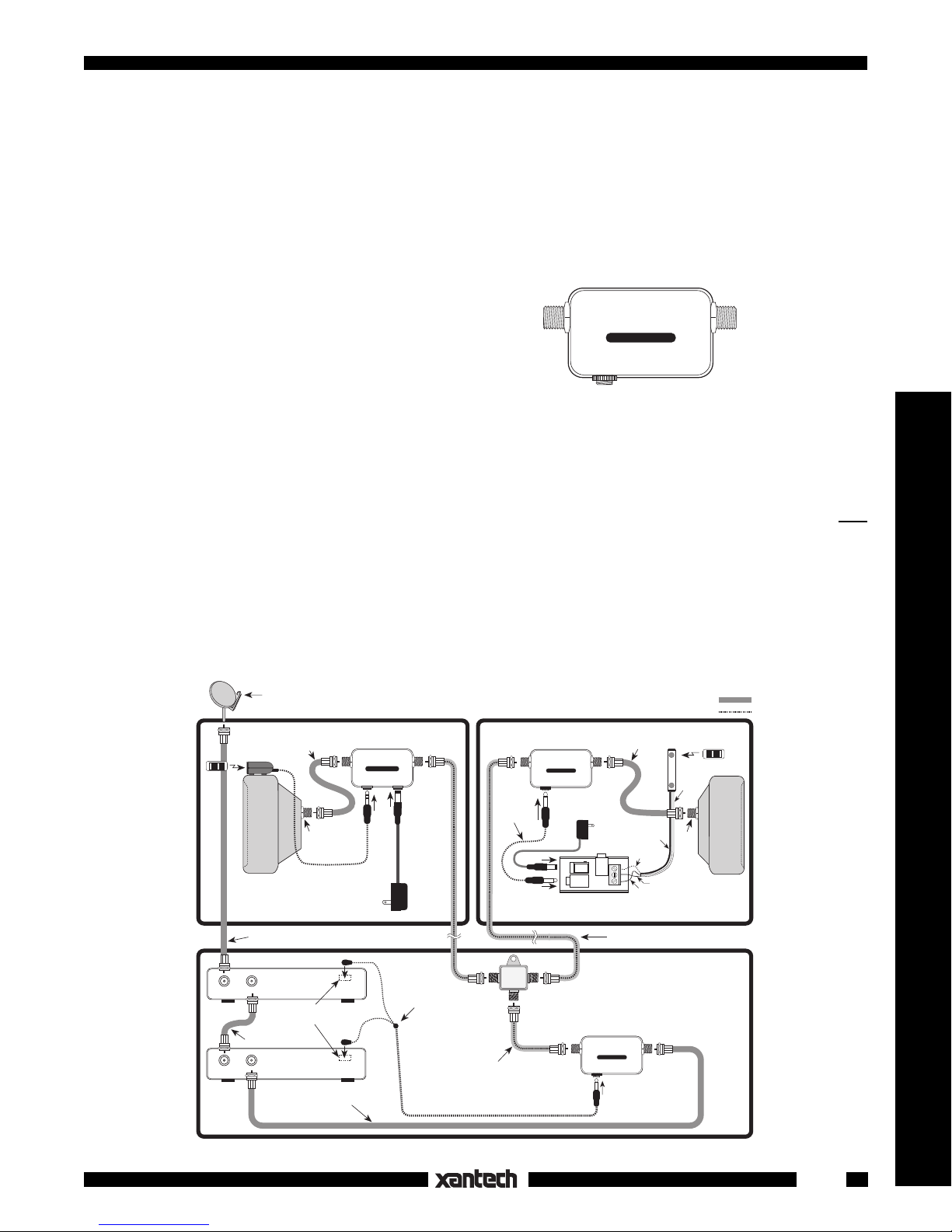
Fig. 1 Model CPL10 RF/IR Coupler
INSTALLATION
Fig. 2 illustrates a simple installation using CPL10 Couplers in an IR repeater system. Control of a satellite
receiver and a VCR from two remote rooms is accomplished over the same coaxial cable that carries the
TV signal. When configuring this type of system, keep the following items in mind:
1. CPL10's may be used for both injecting and extracting the IR signal on the coax at the IR receiver
and
equipment ends, as shown.
2. REMOTE ROOM 1 is an example of how any 3-lead Xantech IR receiver (or keypad) may be used in
an Xtra Link type system. A CB12 Connecting Block makes the necessary connections between the
three leads of the 480-00 "Dinky Link" IR Receiver, the 781RG Power Supply and the CPL10 Coupler.
3. REMOTE ROOM 2 shows the use of a 291-10 IR Receiver and an INJ94 Injector. Use the INJ94
instead of the CPL10 any time you use a Xantech IR receiver equipped with a quick connect stereo
mini plug.
Hand Held
Remote
RF IN OUT TO TV
RF IN
Satellite Dish
291-00
IR RECEIVER
TV
REMOTE
ROOM 2
Coaxial Cable
Coaxial
Cable
OUT TO TV
Short Coaxial
Cable
RF IN
Emitter
SATELLITE
RECEIVER
(Back Panel)
IR Sensor Windows
on
Front Panels
VCR
(Back Panel)
INJ94 INJECTOR
TV
RCVR
781RG
Power Supply
To 120 V AC
(unswitched)
Emitter
INJ94 INJECTOR
IR
INPUT
+12 V
286M
Dual Blink-IR™
Mouse Emitter
Assembly
Short Coaxial
Cable
3.5/3.5mm
Cable
OUT
IN
CPL10
COUPLER
RF/IR
CPL10 COUPLER
IR
Power Supply
PWR
OUT
OUT
200-00
2-Way RF SPLITTER
DC Passing
RF
781RG
To 120 V AC
(unswitched)
CB12
Connecting Block
CPL10
COUPLER
RF/IR
CPL10 COUPLER
IR
TV SIGNAL PATH
IR REMOTE CONTROL PATH
Cable
GS
V
+12V
OUT
Red
(or white)
Stripe
480-00
Dinky Link™
IR Receiver
GND
3-Wire
Ribbon
Cable
RF IN
REMOTE
ROOM 1
Short Coaxial
RCVR
IR
Room-to-Room Coaxial Cables
EQUIPMENT
AREA
RF
Hand Held
Remote
TV
Accessories
Fig. 2 Using CPL10's in a Basic System
Coaxial
Cable
1
4. The 2-way RF splitter used in the equipment area must be a DC Passing type, such as the Xantech
Model 200-00, as shown. This ensures that the IR coded pulses are passed through the RF splitter
to the CPL10 to drive the 286-00 emitters.
5. Be sure the CPL10 is placed between the source equipment (in this example a VCR) and the 2-way
RF splitter as shown.
6. Room-to-room coaxial cable lengths, exclusive of RF signal considerations, may be up to one mile in
length, using RG-6, for successful IR signal transmission.
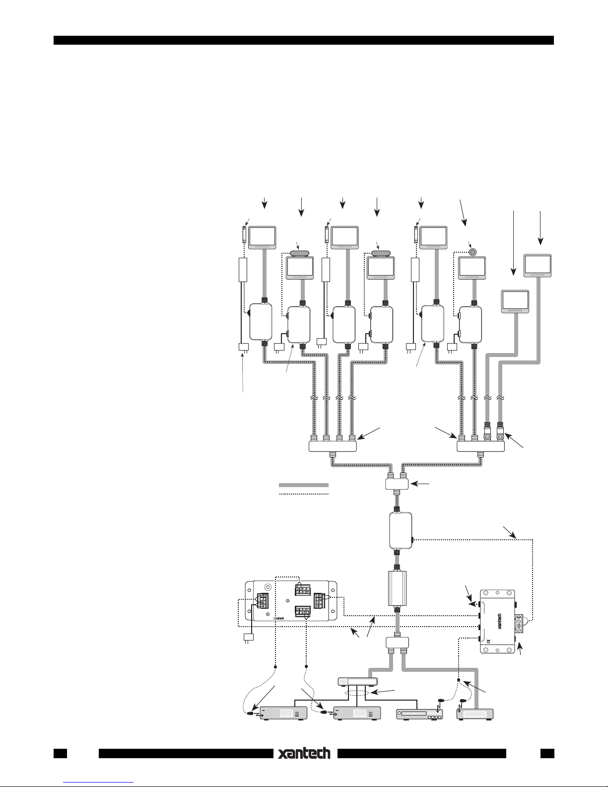
ADVANCED MULTIROOM SYSTEMS
Fig. 3 illustrates an advanced system using a variety of connection
and control techniques typical of
complex multiroom installations. It is
configured as follows:
1. Both CPL10 Couplers and
INJ94 Injectors are used in the
Six Remote Rooms, each configured in the same manner as shown in Fig. 2
480-00
CB12
TV
291-10
TV TV TV
480-00 480-00
TV
291-10 490-30
CB12
CB12
TV
Two Remote Rooms
not
configured
with IR receivers
remote rooms with various Xantech IR Receivers.
As a rule of thumb, use the
CPL10 with the CB12 Connect-
RF
IR
CPL10
RF/IR
RCVR
+12 V
TV
IR
INJECTOR
INJ94
INPUT
RF
IR
CPL10
RF/IR
RCVR
+12 V
TV
IR
INJ94
INPUT
RF
IR
CPL10
RF/IR
RCVR
+12 V
TV
IR
INJ94
INPUT
TV
ing Block when using Xantech
3-terminal IR receivers or keypads, such as the 480-00 Dinky
Link, the Smart Pads, etc. Use
the INJ94 when using Xantech
IR receivers equipped with a
3.5mm quick-connect stereo
mini plug, such as the 291-10
Injectors (3)
781RG
Power
Supplies (6)
INJ94
CPL10
Couplers (4)
202-00
4-way RF Splitters
DC Passing
Hidden Link, the 490-30 Micro
Link, 480-30 Dinky Link, etc.
2. When configuring multiple
rooms, be sure the RF splitters
RF Signal
IR Signal
200-00
2-way RF splitter
DC Passing
203-00
DC Blockers (2)
(See text, pg 2)
used are DC passing types,
such as Xantech Models 20000 (2-way) and 202-00 (4-way).
Refer to Figs. 2 and 3.
3. Each IR receiver must be locally powered by a 781RG
Power Supply as shown.
4. Note that model 203-00 DC
Blockers are used on the two
coax leads going to the two TV
not
sets in the rooms
receivers. This is a
having IR
must
to
prevent the RF inputs on the
two TV sets from "shorting out"
the IR control signal.
For IR Routing (See text)
0
SR21
1
CODE
7
2
6
SPEAKER RELAY
SUB-
3
5
4
MODULE
GROUP
S
CI
G
V
IR CONFIRM
781RG
Power
Supply
Blink-IR™
SR21
A
OFF = A
ON = B
B
283M
Mouse
Emitters
R+
R+ R– L– L+
R–
L–
L+ L– R– R+
L+
6015900
to stripped-end cables
CPL10
(4 locations)
mini plug
Modulator
(3-Input)
Coupler
AMP
RF
RF/IR
CPL10
IR
RF
IN OUT
A/V Patch
Cords
Combiner
2512
2-way
To additional
emitter(s) on
controlled
device(s) if
needed
6015900
to stripped-end cable
mini plug
789-44
Connecting
EMITTERS
789-44
power supply is
required in this
286M
Mouse Emitter Assembly
Block
IR
RCVR
IR IN
STATUS
GND
+12 VDC
CONNECTING BLOCK
X
12VDC
NOTE: No
case.
Dual Blink-IR™
TV
Fig. 3 Using CPL10's in an
Advanced System
2
Satellite Receiver 1 Satellite Receiver 2
VCR
Cable Box
CPL10

5. If an RF amplifier(s) is used anywhere in the line of coaxial cable between the CPL10 Coupler and the
CPL10 COUPLER
IR
RF
RF/IR
INOUT
CPL10
3.5/3.5mm Mono
Mini Plug Cable
Coaxial cable
to IR receivers
and TVs
RF Amp
CPL10
Short Coaxial
Jumper Cable
Short Coaxial
Jumper Cable
Coaxial cable
from IR controlled
RF sources
CPL10 COUPLER
IR
RF
RF/IR
INJ94 Injectors (or the CPL10's used as Injectors), you
must
use a Xantech BYPASS94 Kit to route
the IR control signals around the amplifier(s) as shown in Fig. 4.
6. Where possible, place RF amplifiers ahead of the CPL10 Coupler, as shown in Fig. 3, instead of using
a bypass kit.
7. To drive the necessary emitters and devices, a 789-44 Connecting Block is connected to the IR jack
on the CPL10 to make four emitter jacks available.
NOTE: NO POWER SUPPLY IS NECESSARY ON THE 789-44 WHEN IT IS USED ONLY AS AN
EMITTER EXPANSION BLOCK, AS IN THIS CASE.
8. Fig. 3 also shows a Xantech SR21 Speaker Relay Module used as an IR Router so that control of two
satellite receivers (or other products having identical IR control codes) can be addressed individually
from any remote room location. (Refer to the SR21 Installation Instructions for information on using
it for IR routing).
In this type of operation, you may program a learning device, such as the Xantech URC-1 Universal
Learning Remote Control or the Smart Pads, with sequence commands (macros). These sequences
would issue channel commands to the remote room TV's to switch them to the modulator channel for
the desired satellite receiver along with the corresponding IR router command for the SR21 -- all with
one button press. You would then program other buttons with the satellite receiver commands.
To program sequences, refer to instructions for the learning device.
9. For information on how to connect and configure modulators and
®
RF amplifiers, refer to Channel Plus
technical information.
Accessories
TROUBLE SHOOTING
1. Perhaps the most common problem encountered is stray IR or RF
interference preventing proper operation of the controlled equipment.
Examples of such interference are:
• Fluorescent, Compact Fluorescent, Neon or Halogen lights,
Neon Art, and light dimmers.
• Direct or reflected sunlight.
• Infrared security sensors (active type).
• RF radiation from TV sets that may be close to IR Receivers.
It may be necessary to move either the interfering source or the IR
receiver to achieve proper operation. Sometimes the Xantech Sun
Filters will help.
2. Check for shorts or opens anywhere between the IR receivers in the remote rooms and the emitters
at the controlled equipment.
• Remember, you must have DC continuity all the way from the IR (IR RCVR) jacks on the Injectors,
through the coax cables to the IR (emitter) jack on the coupler, without shorts to ground.
• Use a Xantech 179-99 Test-IR plugged into the IR (emitter) jack on the coupler to verify that the IR
signal is being received from each room.
• If necessary, use a multimeter in the low Ohms range to check for continuity, shorts, opens, etc.
• Check for open emitters by substituting a known good emitter.
3. If a given component does not work, reposition the emitter. It may not be located directly over the
component’s IR (infrared) sensor receiving “window”. Consult the owner's manual of the unit or the
manufacturer for the exact location of the IR “window”.
CPL10
Fig. 4 Using a Xantech
BYPASS94 Kit
1/16/01
Rev.C
3
 Loading...