

Page 1
INSTALLATION INSTRUCTIONS
MODEL CBCSM1
Current Sensor Connecting Block
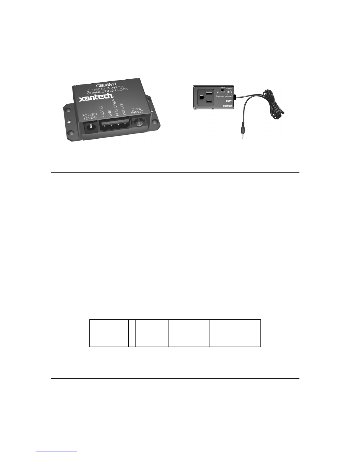
Figure 1 – CBCSM1 Current Sense
Connecting Block
Figure 2 – CSM1 Module (sold seperately)
FEATURES
The CBCSM1, used in conjunction with the CSM1 Current Sense Module (sold separately), will
sense the AC Power State of a component and pass a control voltage to another components
Control Input or voltage controlled dev ice. This allows the CSM1 to operate as a general purpose
current sensor instead of being used exclusively with an MRC44 or MRC88 Controller. The
CBCSM1 will provide Positive or Negative logic on its Pull UP or Pull DOWN terminal
connections.
NOTE:
Requires CSM1 Current Sense Module and 781RG Power Supply both sold separately.
CSM Input: Interfaces with the 3.5mm Stereo Mini plug of the CSM1 Current Sense Module. The
CSM1 detects the Power State of the component and passes a ‘sense’ voltage to the CBCSM1
Connecting Block.
PULL UP: This output will pass a 12vDC voltage whenever the CSM1 detects a power ON state
(Green threshold LED ON). When the CSM1 detects a power OFF state (Green threshold LED
OFF), the PULL UP terminal will be switched to GND (0v). See Table 1.
PULL DOWN: This output will be directly opposite of the PULL UP terminal. The PULL DOWN
terminal is switched to GND (0v) whenever the CSM1 detects a power ON state and will pass
12vDC whenever the CSM1 detects a power OFF state. See Table 1 below.
Component
Power State
PULL UP
Voltage
PULL DOWN
Voltage
CSM1 Threshold
LED Indicator
ON
+12vDC 0v (GND) ON
OFF
0v (GND) +12vDC OFF
Table 1: Power ON/OFF Voltage States
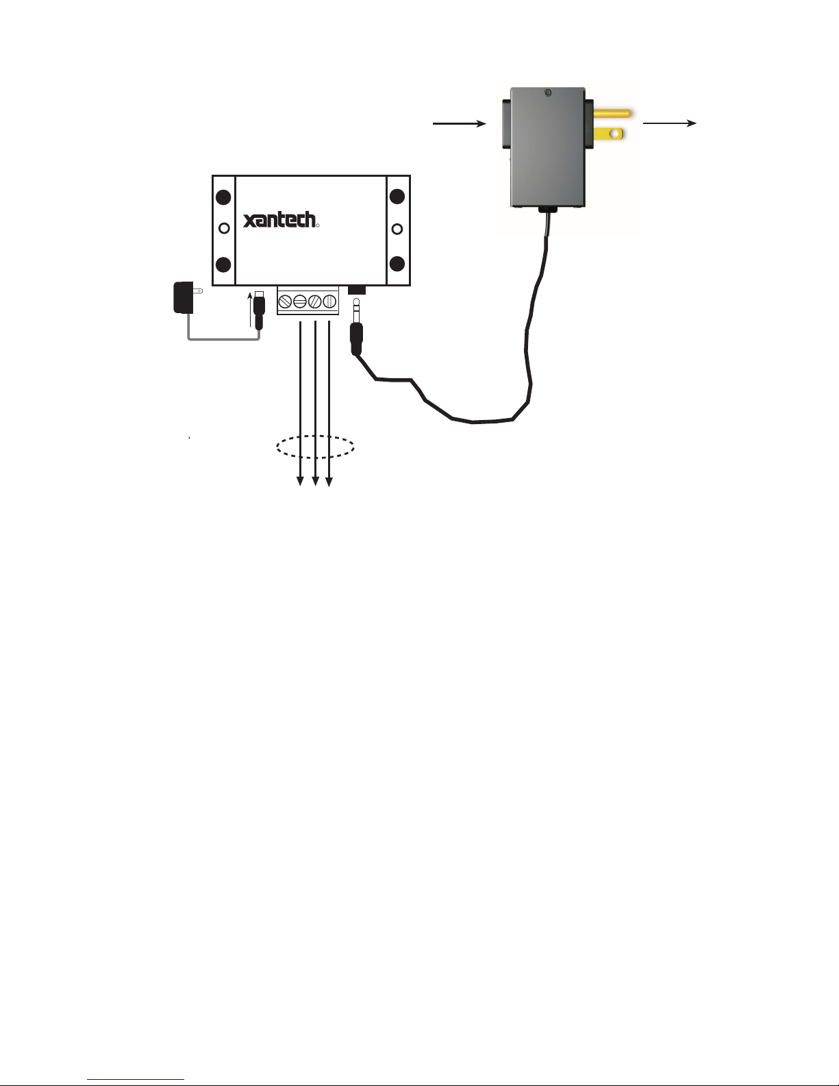
HARDWARE CONNECTIONS
1. Plug the CSM1 (shown in Figure 2) into an unswitched AC Power Source.
2. Plug the 3.5mm stereo mini plug from the CSM1 into the jack labeled CSM Input on the
CBCSM1 Current Sensor Connecting Block.
3. Connect a 12v Power Supply to the 2.1mm Coaxial Power jack on the CBCSM1
4. Interface the desired logic output of the CBCSM1 (Pull Down or Pull Up) to the controlled
source as in Figure 3.
Page 2
To AC Outlet
(Not Included)
From Source
Component
To Device to be controlled
(i.e Relay, Lift etc...)
CSM1
(Not Included)
POWER
12VDC
CSM
INPUT
+12VDC
GND
CBCSM1
PULL DOWN
PULL UP
CURRENT SENSOR
CONNECTING BLOCK
R
To 120 V AC
(unswitched)
781RG
Power
Supply
Figure 3: Installation Connections
CSM1 Threshold Adjustments
a. First, make sure the 3.5mm mini-plug is plugged into the appropriate sense jack on the
CBCSM1 and that it is powered ON via a 781RG Power Supply (not included). (The CSM1
gets low-voltage DC power from the CBCSM1 – not from the AC line.)
b. Select the correct position of the RANGE slider switch – the HI position is for devices with a
high current draw when ON, the LO position is for devices with a low current draw when ON
(based upon the lowest current draw state of the component when ON).
c. Manually turn the component ON.
d. Using a small (1/8” wide) blade screwdriver, rotate the current control to the full CLOCKWISE
position (LO CURRENT).
e. Rotate the control COUNTER-CLOCKWISE (towards the HI CURRENT position) until the
Threshold Adjustment LED goes OFF (Make ‘note’ of this position).
f. Turn the component OFF manually.
g. Rotate the control CLOCKW ISE until the Threshold Adjustment just goes ON.
h. Set the control to a point midway between this and the setting in step ‘e’ above. This should
be the correct setting.
NOTE 1: If you have trouble with the threshold adjustment correctly detecting the ON and OFF
states of the component, try changing the RANGE slider to the opposite position and then try the
adjustment again.
NOTE 2: If the Threshold Adjustment LED does not go ON and OFF with the component power,
make minor adjustments to the threshold adjust until the LED is in proper sync.
XANTECH CORPORATION
12950 Bradley Avenue, Sylmar CA 91342-3829
phone 818.362.0353 • fax 818.362.9506
www.xantech.com
Part No. 08901465 Rev A 02-26-2003
 Loading...