

Page 1
INSTALLATION INSTRUCTIONS
CB12
CONNECTING BLOCK
The Model CB12 provides a low cost means of connecting Xantech "Quick Connect" IR Receivers and
standard 3-wire IR Receivers to one single or one dual emitter and a power supply in an infrared repeater
system.
FEATURES AND SPECIFICATIONS
• Inputs: 1 - "IR RCVR" 3.5mm stereo mini jack. Accepts
any Xantech IR Receiver equipped with a
3.5mm stereo mini plug, such as the 291
series or 490-30.
1 - Three terminal "VGS" block for wired
connection of Xantech IR Receivers and
SmartPad keypads.
• Output: 1 - Emitter "OUT" port (3.5mm mono mini jack).
• Model 282, 283, 284 & 286 Xantech series Mini Emitters may be used.
• 2.1mm coaxial power jack for Xantech 781RG or 782-00 Power Supplies.
• Dimensions: 2-1/8" x 1-1/4" x 3/4"
CAUTION: Plug only Xantech IR Receivers equipped with a stereo mini plug into the IR RCVR jack.
Do not plug emitters or other devices into this jack; to do so may damage emitters and power
supplies!
PWR
OUT
IR
RCVR
Fig. 1 Model CB12 Connecting Block
VGS
Modules & Connecting Blocks
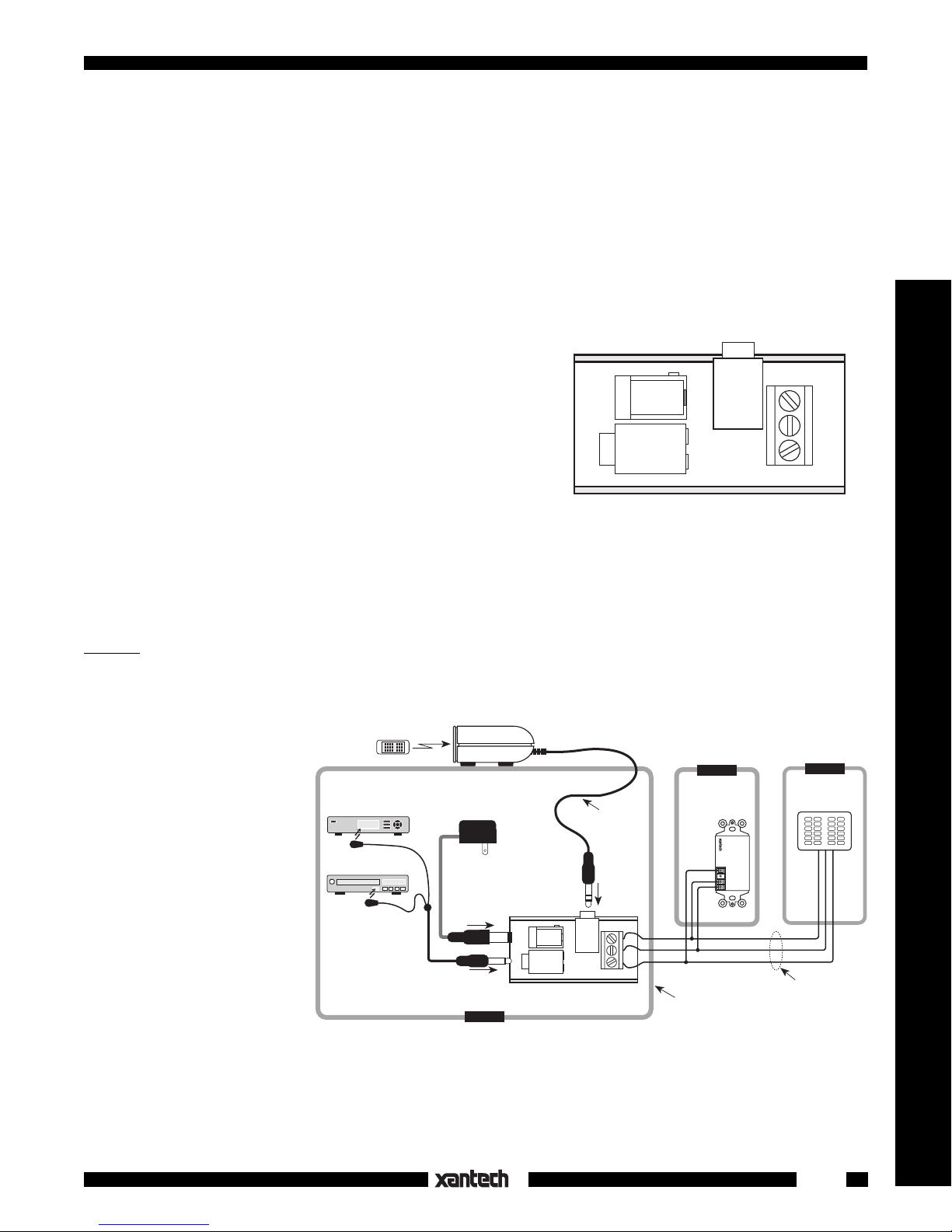
INSTALLATION
Fig. 2 illustrates a typical installation using the CB12 in a
multiroom IR repeater system. In this case a Xantech
291 Hidden Link™ IR Receiver is used to control a
Satellite Receiver and a VCR
in a cabinet behind closed
doors in Room 1. Control of
the same equipment is accomplished from two other
rooms with a Xantech 780-10
J-box IR Receiver and a
Smart Pad™ keypad, by using the 3-terminal "VGS" connector on the CB12
Hand Held
Remote
Satellite Receiver
VCR
Model 286M
Dual Blink IR
Mouse Emitter
Fig. 2 The CB12 in a Typical 3-Room IR Repeater System
291
IR Receiver
781RG
Power Supply
To 120 V AC
(unswitched)
ROOM 1
Quick Connect
PWR
OUT
CB12 Connecting Block
IR
RCVR
7-Foot 3Conductor
Cable with
Mini Plug
VGS
ROOM 2
780-10
J-Box
IR Receiver
®
+12V
+12 VDC
IR OUT
IR OUT
GND
GND
Equipment
Mounted Behind
Closed Doors
780-10
J-BOX RECEIVER
ROOM 3
Smart Pad™
+12V
IR OUT
GND
3-Conductor
Room-to-Room
Cable
(unshielded OK)
(V=+12Volts, G=Gnd., S=IR
Signal). When connecting a system, follow this diagram carefully:
When you use more than 1 keypad and one IR receiver together in a system, use the high current power
supply, model 782-00, in place of the 781RG.
1
Page 2

The OUT port can drive any of the Xantech emitter models in the 282, 283, 284 and 286 series as well as
the 286M shown in Fig. 2.NOTE: Be sure the Power Supplies, in any of these systems, are plugged into
an unswitched AC outlet. This maintains the system in "stand-by" operation so that power-on commands
can be sent to the controlled equipment.INSTALLATION (cont'd)
Fig. 3 illustrates another application of the CB12. In this case it serves as a "break-out" block for the
convenient connection of a 291 IR Receiver to a 3-conductor room-to-room cable in a larger multiroom
system. You may also use it with any other Xantech quick-connect IR Receiver, such as the 490-30, for
the same purpose.
INSTALLATION NOTES:
1. When used as a "break-out" block, you do not need to connect a power supply to the "PWR" jack on
the CB12. Power is supplied on the 3-conductor cable coming from the connecting block in the
equipment room.
Also,
do not plug an emitter into the "OUT" jack in this case. To do so will prevent operation of the
emitters in the equipment room.
2. When paralleling IR receivers, a maximum of 12 is recommended. More than this may result in
unreliable operation due to the buildup of IR noise.
3. The Smart Pad™ keypads may be paralleled in larger numbers. They are not subject to the IR noise
limitation.
4. Mounting: The CB12 may be mounted on any flat surface using the double-sided adhesive tape
supplied.
ROOM 2
291
IR Receiver
Hand Held
Remote
(See Text)
X X
OUT
PWR
CB12
Connecting
Block
RCVR
IR
VGS
3-Conductor Room-to-Room Cable
24 to 18 gauge (unshielded OK)
Fig. 3 The CB12 used as a "Break-Out" Block
+12V
IR OUT
GND
ROOM 3
®
+12 VDC
IR OUT
GND
+12V
780-10
J-BOX RECEIVER
IR Receiver
GND
IR OUT
780-10
J-Box
Smart
Pad™
490-30
Micro Link™
IR Receivers
Series
ROOM 4
To 120 V AC
(unswitched)
789-44
12VDC
+12 VDC
GND
STATUS
IR IN
®
RCVR
IR
3-Wire
Cable
Red
Stripe
CONNECTING BLOCK
789-44
EMITTERS
480-00
Dinky Link™
IR Receiver
Satellite Receiver
VCR
AV Receiver
GND
+12V
IR OUT
782-00
Power
Supply
Connecting Block
MAIN ROOM 1, EQUIPMENT CABINET, ETC.
282M
Mouse Emitter
282M
Emitter
283M
Blink IR Emitter
286M
Dual Blink IRs
(to other
controlled
devices)
NOTE: Be sure the power supplies, in any of these systems, are plugged into an un-switched AC outlet.
This maintains the system in "stand-by" operation so that power-on commands can be sent to the controlled
equipment.
2
8-30-00
CB12
 Loading...