

Page 1

INSTALLATION INSTRUCTIONS
CA1250
DISTRIBUTED SOUND POWER AMPLIFIER
User Manual
Page 2
Page2 Model CA1250
IMPORTANT SAFETY INSTRUCTIONS-READ BEFORE OPERATING EQUIPMENT
Page 3

Model CA1250 page:3
13. Cleaning – Clean only with dry cloth.
14. Power Lines – An outdoor antenna should be located away from the power lines.
15. Nonuse Periods – The power cord of the appliance should be unplugged from the outlet when left unused for a long period of
time.
16. Accessories: Only use attachme nts /ac ce ssor ies specified by the manufacturer.
17. Object and Liquid Entry – Care should be taken so that objects do not fall and liquids are not spilled into the enclosure
through openings.
18. Damage Requiring Service- The appliance should be serviced by qualified service Personnel when:
A. The Power-supply cord or the plug has been damaged; or
B. Objects have fallen, or liquid has spilled into the appliance; or
C. The appliance has been exposed to rain; or
D. The appliance does not appear to operate normally or exhibits a marked change in performance; or
E. The appliance has been dropped, or the enclosure damaged.
19. Servicing – The user should not attempt to service the appliance beyond that described in the operating instructions. All other
servicing should be referred to qualified service personnel.
Page 4

Page: 4 Model CA1250
Introduction
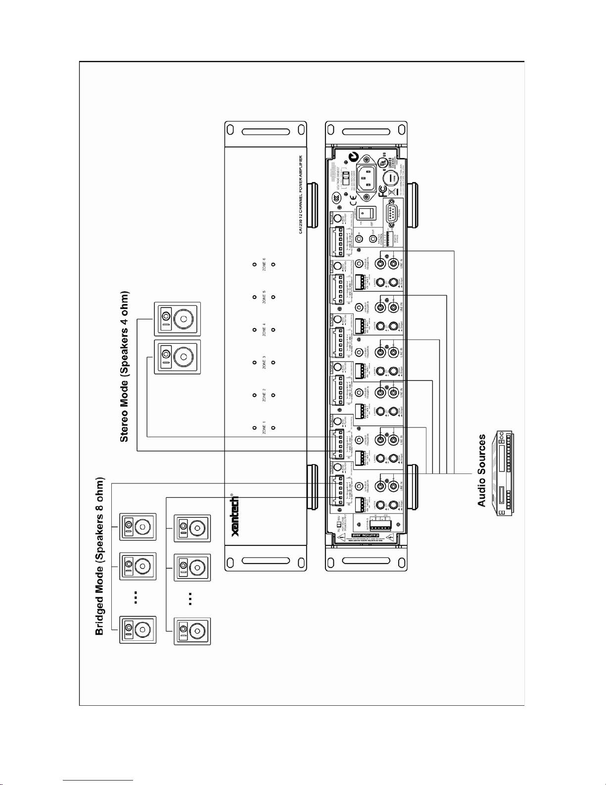
The CA1250 is a major step forw ard in inst allati on a mplifier s technology. Twelve mono Z one power amplifier s, featur ing 85% class D
design technology, can operate as 6 independent Zone amplifiers. Self-explanatory Input and Output connections are easy to follow
since any of the 12 mono amplifiers can be connected to either 70-Volt, 8-Ohm or 4-ohm speaker circu it s.
Each of the 12 mono amplifiers has their own input and output connectors and level Controls. Up to 6 stereo Zones (4-ohm or
70-Volt at 50Watts/channel), 6 mono/bridged Zone amplifiers (110 Watt bridged 8-ohm or 140-Volt). Each zone can be configured
independently allowing a comb ination o f Ster eo 4-ohm or 7 0Volt a nd M ono/Bridg ed 8-oh m o r 140 Volt Zone s. Du al-funct ion LEDs on
the front panel provide bot h ac tivity and Clip in dicatio n for e ach pa ir of a mplifi ers, w hich al so hav e their ow n butto n-selec table L imiter ;
Stereo/Bridge modes and 4-ohm/70V mod es are als o sele cta ble.
The Ch. Input Line/Bus switch selects between either the Bus Input (button depressed) or the individual Zone’s Input signal.
Additional features include: any amplifier with no signal at its input is automatically shut off and the CA1250 is able to operate either
on 110V-120V/60Hz or 220V-240V /50Hz AC mains.
Page 5

Model CA1250 Page:5
Features and Functions
AC Mains. The CA1250 comes configured to connect to 110V-120V/60Hz mains. For use with 220V-240V/50Hz mains
set the rear panel Voltage Select switch to220V-240V (also, repla ce the T10.0AL/250V fuse with a T5.0AL/250V fuse).
Front Panel
1. Independently switchable on each Zone between its zone-specific stereo inputs and a mono global audio balanced input.
2. Each Zone is also independently Stereo/Bridge switch to select a single mono output for single speaker use or higher output
power.
3. Each Zone independently controllable via RS232, IR and voltage trigger lines.
4. Each Zone has -20dB Limiter and independent MUTE trigger inputs (activated by +3 to +30V DC).
5. Each Zone individual Trigger Outputs (+12V DC) to indi cate the stat us of each Zone.
6. The unit has front panel “zone on” and “zone overload” indicators.
7. Master Global Trigger In (+3 to +30V DC) and Trigger Out (+12V DC).
8. Detachable screw-terminal connectors for Global Balanced Audio Input/Output, IR, Sense and Speaker Outputs.
Page 6
Page: 6 Model CA1250
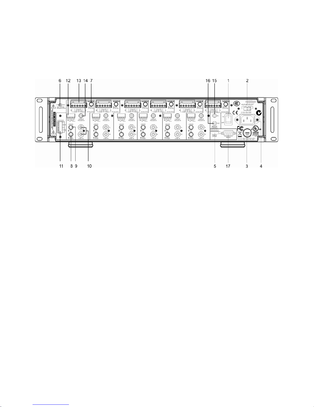
Rear Panel
1. Power: This switch turns the AC mains On or OFF.
2. Voltage: Select either110V- 120V/220V-240V for your local voltage level. Please check your local voltage for user reference.
3. Fuse: When using with 220V-240V/50Hz for T5.0AL/250V fuse, using with 110V-120V/60Hz for T 10.0AL /250V fuse.
4. AC input: 3-Pin ground cable connect the unit to external AC Power Supply.
5. Remote Bypass Setting.
6. Selectable 70V and 100V constant voltage speaker output
7. 4 ohm / 70V Button: Leave this switch in the up position if you are connecting 4-ohm or 8-ohm speaker circuit(Stereo mode).
Depress the button to connect a 70V speaker circuit.
8. Stereo/Bridge B utton: For stereo, or d ual-zon e mono operation , at 5 0 Wat t s per c hannel leave th is in t he up positi on. To combine
(i.e. Bridge) the two into a 100-Watt mono amplifier, depress t he butt on. In Br idge mod e, the 4 ohm / 70V butt on must be in the 4
ohm / 70V button must be in the 4 ohm position(depressed) to allow for the 8-ohm speaker circuit, not4-ohms! In bridge mode,
an amplifier encounters a load that is about one half of its actual value a 4-ohm load would therefore be 2-ohms to a bridged
amp and if the amplifier isn ’t desig ned to run Safely into such a low impedance (which the CA1250 i s not) dam age may oc cur to
the amplifier. We do not recommend connecting a 70V Speaker circuit while in Bridge mode as the output will be at 140V and
the sound can be distorted.
Page 7

Model CA1250 Page: 7
9. Limiter In / Out Button: T he Lim iter In/ Out button activat es a pre-set input limiter, which help s re duc e the lev el o f acc idental loud
noises and clipping distortion for each Zone(both channels of each Zone).
10. Ch Line Input: These inputs allow connection of sources directly to the individual channels. This input allows Stereo, line -level
source or two separate mono audio sources. If you Bridge the Zone’s pair of amplifiers into an 8-ohm speaker circuit, use the
Left input and connect a mono source.
11. For Bus Inp ut: These RCA connectors and a screw terminal strip are provided to connect your mixer, stereo / preamp, CD
player or other audio media device. (Note: use only one type of source). For Bus outputs: These RCA connectors are simply in
parallel with the Bus Inputs and enable you to interconnect the CA1250 with another CA1250 or amplifier. ( Note: only the Input
Bus signals will be pat ched to Output ).
12. IR remote/ mute/ status port.
13. Speaker Connections: Insert bar e wire ends here and ti ghten the retaining s crews to secure properly. For a stereo Z o ne or dual
mono Zones, connect the + and –system leads from each Zone to one +4 ohm and its adjacent-Neg terminal in the L& R
terminal groupings. In Bridge mode, connect the + and – leads from an 8-ohm speaker circuit (not 4-ohms-see Stereo/ Bridge
Button section above) to each of the +4 ohm terminals.
14. Line/Bus Button: Each Zone’s input source can be selected using this switch. Depress the button to select the audio program
coming from the Bus Input or leave it in the up position to use the Zone’s Line Input.
15. Master control input.
16. Master control output.
17. RS232: The RS232 serial port allows two-way communication control by a home automation system.
Page 8

Page: 8 Model CA1250
Physical location and mounting
1. The CA1250 is conv ect ion co ole d. T hat is, it depends on t he natural free flow of air up through the slot perforations in the bottom
plate, over the internal heat dissipating fins, then out the top cover, for adequate cooling.
2. The CA1250 is designed for mounting into standard 19" (483mm) racks or on flat horizontal surfaces.
3. If mounted in an equipment cabinet or other confining location, allow at least 2 inches of space above the top cover (see Fig.
above). Be sure there are large openings in the shelf below the unit and in the cabinet to allow the entry of cool air and the
escape of warm air.
4. If the cabinet contains other heat generating components or you are using several CA1250’s, you will have to pay even closer
attention to adequate ventilation.
5. Do not hesitate to use fans (quiet, boxer type), if necessary, to ensure a constant flow of air through the CA1250's and the other
heat generating components.
6. W hen installing the CA1250 in a rack, please use racks that feature rear support provision. Adding a single RU (Rack Unit)
above and below the CA1250 will improve convection in heavy use applications. [One Rack Unit size = 1-3/4" (44.5mm) in
height].
7. In some installations, y ou may hav e large bun dles o f w ire and ca ble to accom modate audio and speaker connections. Be sure t o
allow enough room for the leads and dress them in such a manner so as not to block airflow.
Page 9

Page: 9 Model CA1250
Technical specifications
Continuous Output Power: 30W per channel 8ohms at 1k Hz THD 0.1%
50W per channel 4ohms at 1k Hz THD 0.1%
100W Bridged 8ohms at 1k Hz THD 0.1%
30W per channel 70V/100V at 1k Hz THD 0.1%
Total Harmonic Distortion: 0.1% @ 10W
Signal-to-Noise Ratio: 90dB A-Weighted 1Kz
Channel Separation: 65dB 1Kz
Frequency Response: 20Hz to 20kHz+/-1Db
Input Sensitivity: 600mV @ 30W
Tone Control: Bass 100Hz +/-12dB
Treble 10k Hz+/-12Db
Global Audio Balanced Input Impedance: 600 Ohms
Line Input Impedance: 47 k-Ohm
Rack mounting requirements: 19 inch rack width, 2U rack height
Power Requirements: 115VAC 60Hz 10A/ 230VAC 50Hz 5A
Dimensions: W430WxH88XD416mm
Weight: 22 Kg (48.4lbs)
Page 10
Page:10 Model CA1250
Page 11

Model CA1250 Page:11
Block Diagram for CA1250
Page 12

Page: 12 Model CA1250
Xantech® is a registered trademark of Xantech LLC
Windows® and Microsoft® are registered trademarks of Microsoft Corporation.
IBM® is a registered trademark of International Business Machines Corporation.
All other trademarks are the properties of their registered owners.
Xantech LLC
1969 Kellogg Ave, Carlsbad, CA 92008 | Xantech.com
Installation Instructions, CA1250 © 2011 Xantech LLC
Document # xxxxxxxxxxxx
This document is copyright protected. No part of this manual may be copied or reproduced in any form without prior written
consent from Xantech LLC. Xantech LLC shall not be liable for operational, technical, or editorial errors/omissions made in
this document.
© 2011 Xantech LLC
 Loading...