

Page 1

xdt
amOfm@stereo@dual@tuner
owner¸s@manual
tŠƒ“Ž@Ÿ”š@ˆ”—@…Š””˜‹“‰@xantechN@r‡ƒ†@™Š‹˜@’ƒ“šƒ‘@…ƒ—‡ˆš‘‘Ÿ@™”@‰‡™@™Š‡@„‡˜™@•‡—ˆ”—’ƒ“…‡@ˆ—”’@™Š‹˜@š“‹™N
Page 2

2
Important Safety Instructions
Y
CAUTION
<
DO NOT REMOVE THE PROTECTIVE HOUSING USING
SCREWDRIVER.
<
IF THIS PRODUCT DEVELOPS TROUBLE, MAKE A CONTACT
WITH OUR SERVICEMAN, AND DO NOT USE THE PRODUCT IN
A TROUBLED STATE.
CAUTION: TO REDUCE THE RISK OF ELECTRIC SHOCK, DO NOT
REMOVE COVER (OR BACK). NO USER-SERVICEABLE PARTS
INSIDE. REFER SERVICING TO QUALIFIED SERVICE PERSONNEL.
E
R
The lightning flash with arrowhead symbol, within an
equilateral triangle, is intended to alert the user to the
presence of uninsulated "dangerous voltage" within
the product’s enclosure that may be of sufficient
magnitude to constitute a risk of electric shock to
persons.
The exclamation point within an equilateral triangle is
intended to alert the user to the presence of
important operating and maintenance (servicing)
instructions in the literature accompanying the
appliance.
WARNING : TO PREVENT FIRE OR SHOCK
HAZARD, DO NOT EXPOSE THIS APPLIANCE TO
RAIN OR MOISTURE.
Important Safety Instructions
1) Read these instructions.
2) Keep these instructions.
3) Heed all warnings.
4) Follow all instructions.
5) Do not use this apparatus near water.
6) Clean only with dry cloth.
7) Do not block any ventilation openings. Install in accordance
with the manufacturer's instructions.
8) Do not install near any heat sources such as radiators, heat
registers, stoves, or other apparatus (including amplifiers)
that produce heat.
9) Do not defeat the safety purpose of the polarized or
grounding-type plug. A polarized plug has two blades with
one wider than the other. A grounding type plug has two
blades and a third grounding prong. The wide blade or the
third prong are provided for your safety. If the provided plug
does not fit into your outlet, consult an electrician for
replacement of the obsolete outlet.
10) Protect the power cord from being walked on or pinched
particularly at plugs, convenience receptacles, and the point
where they exit from the apparatus.
11) Only use attachments/accessories specified by the
manufacturer.
12) Use only with the cart, stand, tripod,
bracket, or table specified by the
manufacturer, or sold with the
apparatus. When a cart is used, use
caution when moving the
cart/apparatus combination to avoid
injury from tip-over.
13) Unplug this apparatus during lightning
storms or when unused for long periods of time.
14) Refer all servicing to qualified service personnel. Servicing
is required when the apparatus has been damaged in any
way, such as power-supply cord or plug is damaged, liquid
has been spilled or objects have fallen into the apparatus,
the apparatus has been exposed to rain or moisture, does
not operate normally, or has been dropped.
<
Do not expose this apparatus to dripps or splashes.
<
Do not place any objects filled with liquids, such as vases,
on the apparatus.
<
Do not install this apparatus in a confined space such as a
book case or similar unit.
<
The apparatus draws nominal non-operating power from the
AC outlet with its POWER switch in the off position.
AC POWER CORD CONNECTION
CAUTION:
TO PREVENT ELECTRIC SHOCK, MATCH WIDE BLADE OF PLUG
TO WIDE SLOT, FULLY INSERT.
For CANADA
This equipment has been tested and found to comply with the
limits for a Class B digital device, pursuant to Part 15 of the FCC
Rules. These limits are designed to provide reasonable
protection against harmful interference in a residential
installation. This equipment generates, uses, and can radiate
radio frequency energy and, if not installed and used in
accordance with the instructions, may cause harmful
interference to radio communications. However, there is no
guarantee that interference will not occur in a particular
installation. If this equipment does cause harmful interference
to radio or television reception, which can be determined by
turning the equipment off and on, the user is encouraged to try
to correct the interference by one or more of the following
measures:
• Reorient or relocate the equipment and/or the receiving
antenna.
• Increase the separation between the equipment and
receiver.
• Connect the equipment into an outlet on a circuit different
from that to which the receiver is connected.
• Consult the dealer or an experienced radio/TV technician for
help.
CAUTION
Changes or modifications to this equipments not expressly
approved by the manufacturer for compliance will void the
user's warranty.
For U.S.A.
Page 3

3
Contents Remote Control Unit
Read this before operation
• Choose the installation location of your unit carefully. Avoid
placing it in direct sunlight or close to a source of heat. Also
avoid locations subject to vibrations and excessive dust, heat,
cold or moisture.
•
Do not open the cabinet as this might result in damage to the
circuitry or electrical shock. If a foreign object should get into
the set, contact your dealer.
• When removing the power plug from the wall outlet, always
pull directly on the plug, never yank the cord.
• Do not attempt to clean the unit with chemical solvents as this
might damage the finish. Use a clean, dry cloth.
• Keep this manual in a safe place for future reference.
Maintenance
If the surface of the unit gets dirty, wipe with a soft cloth or
use diluted mild soap liquid. Be sure to remove any excess
completely. Do not use thinner, benzine or alcohol as they may
damage the surface of the unit.
Before Use
CAUTION
The product shall not be exposed to dripping or splashing and
that no object filled with liquids, such as vases, shall be placed
on the product.
Do not install this equipment in a confined space such as a
book case or similar unit.
Remove the battery compartment cover.
Insert two "AAA" (R03, UM-4) dry batteries. Make sure that the
batteries are inserted with their positive " " and negative " "
poles positioned correctly.
Close the cover.
Battery Replacement
If the distance required between the remote control unit and
main unit decreases, the batteries are exhausted. In this case
replace the batteries with new ones.
Precautions concerning batteries
• Be sure to insert the batteries with correct positive " " and
negative " " polarities.
• Use batteries of the same type. Never use different types of
batteries together.
• Rechargeable and non-rechargeable batteries can be used.
Refer to the precautions on their labels.
• When the remote control unit is not to be used for a long time
(more than a month), remove the batteries from the remote
control unit to prevent them from leaking. If they leak, wipe
away the liquid inside the battery compartment and replace the
batteries with new ones.
• Do not heat or disassemble batteries and never dispose of old
batteries by throwing them in a fire.
3
2
1
The provided Remote Control Unit allows the unit to be operated
from a distance.
When operating the remote control unit, point it towards the
REMOTE SENSOR on the front panel of the unit.
•
Even if the remote control unit is operated within the effective
range, remote control operation may be impossible if there are
any obstacles between the unit and the remote control.
•
If the remote control unit is operated near other appliances
which generate infrared rays, or if other remote control
devices using infrared rays are used near the unit, it may
operate incorrectly. Conversely, the other appliances may
operate incorrectly.
Battery Installation
Important Safety Instructions . . . . . . . . . . . . . . . . . . . . . . . . . . . . 2
Contents . . . . . . . . . . . . . . . . . . . . . . . . . . . . . . . . . . . . . . . . . . . . . . . 3
Before Use . . . . . . . . . . . . . . . . . . . . . . . . . . . . . . . . . . . . . . . . . . . . 3
Remote Control Unit . . . . . . . . . . . . . . . . . . . . . . . . . . . . . . . . . . . . 3
Connection . . . . . . . . . . . . . . . . . . . . . . . . . . . . . . . . . . . . . . . . . . . . 4
Names of Each Control . . . . . . . . . . . . . . . . . . . . . . . . . . . . . . . . . . 6
Radio Reception . . . . . . . . . . . . . . . . . . . . . . . . . . . . . . . . . . . . . . . . 8
Preset Tuning . . . . . . . . . . . . . . . . . . . . . . . . . . . . . . . . . . . . . . . . . . 9
Troubleshooting . . . . . . . . . . . . . . . . . . . . . . . . . . . . . . . . . . . . . . . 10
Specifications . . . . . . . . . . . . . . . . . . . . . . . . . . . . . . . . . . . . . . . . 11
Appendix
A (RS-232 Commands). . . . . . . . . . . . . . . . . . . . . . . . 12
Page 4
4
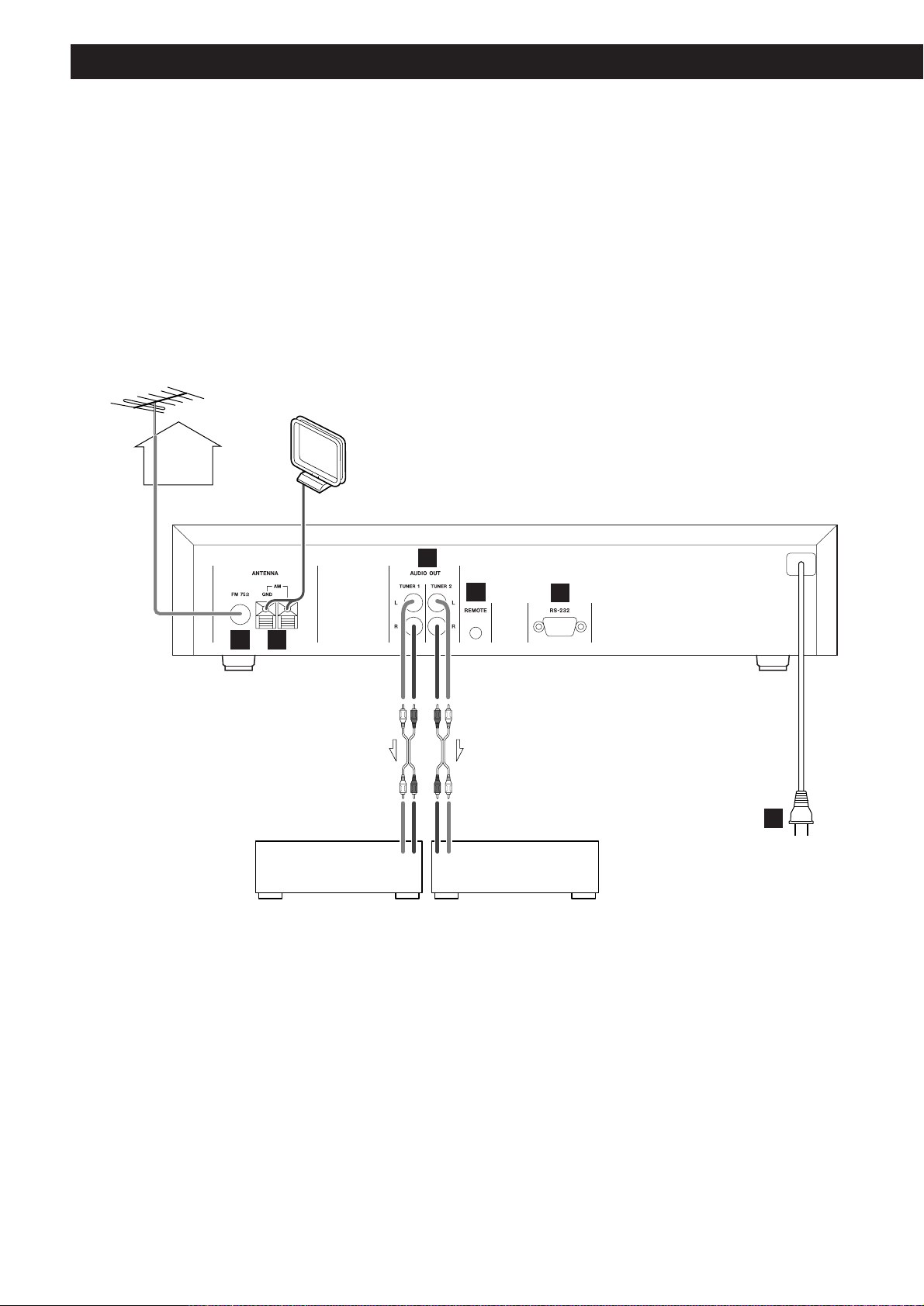
Connection
TUNER IN TUNER IN
RLRL
Amplifier Amplifier
CAUTION
Turn off the power of all the equipment before making connections.
Read instructions of each component you intend to use with this unit.
<
Be sure to insert each plug securely. To prevent hum and noise, do not bundle the connection
cords with the power cord.
A B
C
E
F
D
Page 5
5
AUDIO OUT
Connect the component with RCA pin cords. Make sure to
connect :
white plug wwhite jack(L:left)
red plug
w
red jack(R:right)
Power cord (AC)
Be sure to connect the power cord to an AC outlet which
supplies the correct voltage.
Hold the power plug when plugging or unplugging the power
cord.
REMOTE
Used for a wired remote control unit (optional).
RS-232
Used for a wired RS-232 standard remote control unit
(optional).
F
E
D
C
FM Antenna
Connect an outdoor FM antenna to the FM 75Ω socket.
Generally, a 3-element antenna will be sufficient; if you live
in an area where the FM signals are particularly weak, it
may be necessary to use one with 5 or more elements.
If standard FM broadcast frequencies are available via your
cable service, you may connect your 75 ohm FM antenna
jack to your cable system. Please contact your cable
service to discuss this option.
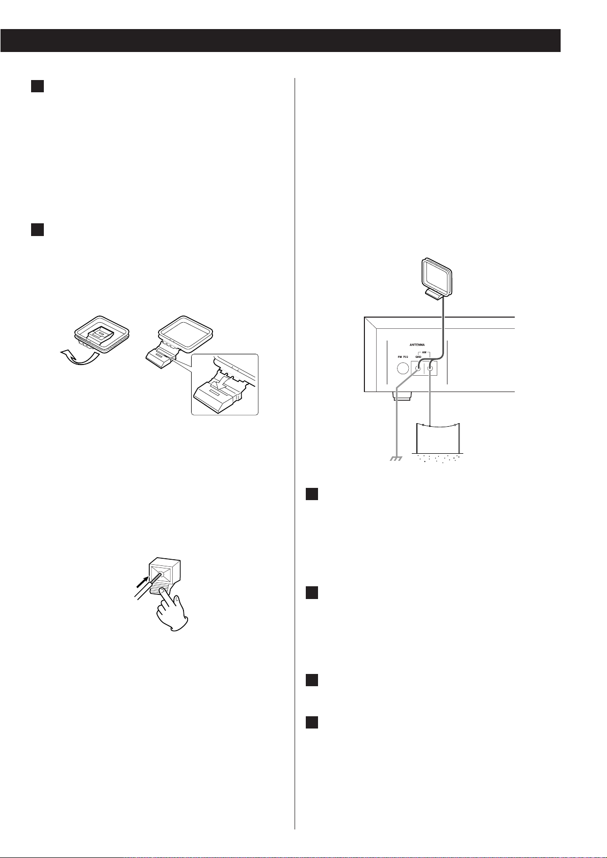
AM Indoor Loop Antenna
The high-performance AM loop antenna provided with this
unit is sufficient for good reception in most areas.
To stand the loop antenna on a surface, fix the claw to the
slot.
Connect the loop antenna's wires to the AM antenna
terminals as shown.
How to connect
Press the lever, insert the end of the cord, then release the
lever. Make sure it is fastened securely by pulling the cord
lightly. Make sure only the bare, stripped wire is inserted in
the jack and that no plastic insulation is preventing contact
between the antenna wire and terminal.
Place the antenna on a shelf, for example, or hang it on a
window frame, etc., in the direction which gives the best
reception, as far away as possible from the entire system,
speaker cords and the power cord, to prevent unwanted
noise.
12
B
A
< If the AM loop antenna provided does not deliver sufficient
reception (often due to being too far from the transmitter or
in a concrete building, etc.), it may be necessary to use an
outdoor AM antenna.
Use either a high quality commercial AM antenna or, if not
available, an insulated wire more than 15 ft (5 m) long, strip
one end, and connect this to the terminal as shown.
The antenna wire should be strung outdoors or indoors near
a window. For better reception, connect the GND terminal to
a reliable ground.
Note:
Even when using an outdoor AM antenna, do not disconnect
the AM loop antenna.
Page 6

6
Names of Each Control
C E F G H IDB J
K K
E F G H ID JA
Buttons for TUNER 1 Buttons for TUNER 2
C
J
H
E
F
G
D
I
J
H
E
F
G
D
I
Page 7
7
Note:
To simplify explanations, instructions refer to names of buttons and controls on
the front panel, making no mention of the use of remote control unit.
The equipment draws nominal non-operating power from the AC outlet with
its POWER switch in the OFF position.
REMOTE SENSOR
When operating the remote control unit, point it towards the REMOTE SENSOR.
STANDBY indicator
This indicator lights when the unit is in the standby mode.
When the unit is turned on, it goes off.
POWER switch
Press this switch to turn the unit on or off.
FM button, AM button
Use these buttons to select FM or AM.
FM MODE button
Use this button to select stereo or monaural.
PRESET button
Use this button to select the preset tuning mode.
DIRECT button
Use this button to select the manual tuning mode.
You can use the numeric buttons to directly input frequency numbers.
MEMORY button
Use this button to store preset channels into memory.
TUNING/PRESET buttons
Use these buttons to tune in a station.
Numeric buttons
These buttons are used either to input frequency numbers or to select preset
stations.
Display
K
J
I
H
G
F
E
D
C
B
A
Page 8

8
Radio Reception
When the TUNING/PRESET button is pressed momentarily (0.5
second or less), the frequency changes by a fixed step.
FM : 0.2 MHz steps
AM : 10 kHz steps
Press the TUNING/PRESET button repeatedly until the station
you want to listen to is found.
Pressing this button alternates between Stereo mode and
Mono mode.
Stereo
FM stereo broadcasts are received in stereo and the
"STEREO" indicator lights in the display.
Mono
To compensate for weak FM stereo reception, select this
mode. Reception will now be forced monaural, reducing
unwanted noise.
Press the POWER switch to turn the unit on.
1
Select the AM or the FM band by pressing the corresponding
button.
2
Press the DIRECT button to select the manual tuning mode.
3
Select the station you want to listen to.
<
"TUNED" is displayed when a broadcast is correctly tuned in.
Auto Selection
A
4
FM MODE Button
Example
To select FM 88.30 MHz : 8q8q3
To select AM 1220 kHz : 1q
2q2q0
<
When no button is pressed for 3 seconds, the mode will be
cancelled.
1 32 4 32 4
TUNER 1 TUNER 2
FM MODE
(TUNER 1)
FM MODE
(TUNER 2)
Hold down the TUNING/PRESET button for 0.5 to 2 seconds.
When a station is tuned in, the tuning process will stop
automatically.
If you want to stop the tuning process, press the
TUNING/PRESET button.
Manual Selection
(Selecting stations which cannot be tuned automatically)
B
Direct Tuning
Input the frequency numbers with the numeric buttons.
C
Page 9

9
Preset Tuning 1
While the MEMORY indication is flashing select the preset
you would like to use for this station by EITHER:
Scroll up or down using the TUNING/PRESET buttons until the
preset is displayed. Then press the MEMORY button to store
5
21 5
3
5
4
21 5
3
5
4
TUNER 1 TUNER 2
5 5
Manual Memory Presetting
You can store your favorite FM and AM stations into any of the 30
preset locations by:
Select the AM or FM band by pressing the corresponding
band button.
1
Press the DIRECT button to select the “manual tuning” mode.
2
Select the station you would like to store by scrolling through
the station using the TUNING/PRESET buttons or directly tune
the station by using the numeric buttons.
3
Once the station is tuned, press the MEMORY button.
4
To store more stations, repeat steps through .
53
OR enter the 2-digit preset number using the numeric pad. (For
instance “05” will store the station in preset number 5. “25”
will store the station in preset location 25.) The preset will
automatically be stored and the memory indication will stop
flashing.
Page 10

10
Troubleshooting
If you experience any problems with the unit, please take a
moment to look through this chart and see if you can solve the
problem yourself before you call your dealer or service center.
No power
e
Check the connection to the AC power supply. Check and
make sure the AC source is not a switched outlet and that, if
it is, the switch is turned on. Make sure there is power to the
AC outlet by plugging another item such as a lamp or fan.
Cannot listen to any station, or signal is too weak.
e
Make sure the antenna is properly connected.
e
Tune in the station properly.
e
If a TV is near the unit, turn it off.
e
Install the antenna again after relocating it to a better
reception position.
e
An external antenna may be required.
Though the broadcast is stereo, it sounds monaural.
e
Press the FM MODE button.
Remote control doesn't work.
e
Press the POWER switch to turn the unit on.
e
If the batteries are dead, change the batteries.
e
Use remote control unit within the range (5m /15ft) and point
at the front panel.
e
Clear obstacles between the remote control unit and the
main unit.
e
If a strong light is near the unit, turn it off.
If normal operation cannot be recovered, unplug the power cord
from the outlet and plug it again.
Select a preset channel using the numeric buttons.
Or press the TUNING/PRESET button repeatedly until the
desired preset station is found.
3
How to select preset stations
Select the AM or the FM band by pressing the corresponding
button.
1
Memory Backup
Settings are stored permanently, even when power is turned off
and the unit is unplugged.
21 3 21 3
TUNER 1 TUNER 2
Preset Tuning 2
Press the PRESET button.
2
Page 11

11
Specifications
FM Tuner Section (Without notes 98.1 MHz, 65 dBf)
Tuning Range. . . . . . . . . . . 87.5 MHz – 107.9 MHz (200 kHz steps)
Usable Sensitivity (IHF). . . . . . . . . . . . . . . . . . . . . . . . Mono: 15 dBf
50 dB Quieting Sensitivity . . . . . . . Mono: 21 dBf , Stereo: 41 dBf
Total Harmonic Distortion (1 kHz) . . . . Mono: 0.3%, Stereo: 0.4%
Frequency Response . . . . . . . . . . . . . . . . . 30 Hz – 15 kHz, ±1.5 dB
Stereo Separation (1 kHz) . . . . . . . . . . . . . . . . . . . . . . . . . . . . 40 dB
Signal-to-Noise Ratio. . . . . . . . . . . . . Mono: 67 dB, Stereo: 63 dB
AM Tuner Section
Tuning Range. . . . . . . . . . . . . . 530 kHz – 1,710 kHz (10 kHz steps)
Usable Sensitivity . . . . . . . . . . . . . . . . . . . . . . . . . . . . . . . . . 64 dB/m
Total Harmonic Distortion . . . . . . . . . . . . . . . . . . . . 1% at 85 dB/m
Signal-to-Noise Ratio . . . . . . . . . . . . . . . . . . . . . . 40 dB at 85 dB/m
General
Power requirements . . . . . . . . . . . . . . . . . . . . . . . . 120 V AC, 60 Hz
Power Consumption. . . . . . . . . . . . . . . . . . . . . . . . . . . . . . . . . . 12 W
Dimensions (W x H x D) . . . . . . . . . . . . . . . . . . . 435 x 95 x 270 mm
(17-1/8" x 3-3/4" x 10-5/8")
Weight (net) . . . . . . . . . . . . . . . . . . . . . . . . . . . . . . 4 kg (8-13/16 lbs)
Standard Accessories . . . . . . . . . . . . . . . Remote Control Unit x 1
Battery (AAA, R03, UM-4) x 2
AM Loop Antenna x 1
FM adapter x 1
RCA Cord x 2
<
Improvements may result in specifications and features
changing without notice.
<
Illustrations may differ slightly from production models.
ENGLISH
Page 12

>
Appendix A
XDT DUAL AM/FM TUNER
RS-232 COMMANDS
PURPOSE:
This document describes the RS-232 commands that will operate the XANTECH XDT Dual Tuner
through the 9-pin RS-232 connector on the rear panel.
General Information:
Data Rate: 19,200 baud
Parity: None
Word length: 8 data bits, 1 stop bit
Handshake: No RTS/CTS handshaking
Connections: simple 3 wire (Rx, Tx, Gnd) interface
DATA ENTRY PROTOCOL:
The serial buss should follow a standard serial
communications protocol using Line oriented ASCII data
stream. The command line must be followed with a
carriage return for the unit to respond. The unit should
not echo characters received back to the host.
Command Codes:
Character Range Example
X: 0,1 X1 = Power On, X0 = Power Off
T: 1,2 T1 = Tuner 1, T2 = Tuner 2
B: 1,2 B1 = AM, Band 2 = FM
P: 00 - 30 P01 = Preset 1, P30 = Preset 30, P00 (just for status) = No Preset Selected
F: 4 numbers F0890 = 890 AM, F1045 = 104.5 FM
A: 0,1 A0 = Seek Down, A1 = Seek Up
M: 0,1 M0 = Step Down 1 step, M1 = Step Up 1 step
S: Signal Lock / S00 (just for status) = no signal, no stereo, S01 = invalid
Stereo Presence S10 = signal lock (mono), S11 = signal lock (stereo)
Q: Query status Q1 = Status of Tuner 1, Q2 = Status of Tuner 2
of tuner Q3 = Status of both tuners, 1 then 2
N: 0,1 N0 = Step Down 1 Preset, N1 = Step Up 1 Preset
L: 01 - 30 L01 = Set Station as Preset #1
Function
Power Off / On
Tuner #
Band #
Preset #
Frequency Setting
Seek Up / Down
Step Up / Down
1 = locked, 0 = not
1 = stereo, 0 = mono
ask for tuner status
Preset Step Up / Down
Set Preset
Command Examples:
T1B2P01<cr
T2B1F1070L03<cr> would command tuner #2 to set AM frequency 1070 kHz as AM preset #3
To select a station to be tuned and THEN set that station as a preset, would require two commands:
T2B1F1070<cr> would command tuner #2 to select band 1 (AM) and tune to frequency 1070 kHz.
T2L03<cr> would command tuner 2 to set the currently tuned station (in this example AM 1070) as AM preset #3
Query Example:
Q1<cr> would solicit the following response:
Feedback as to the status of tuner #1, which would include band select, station preset, frequency
tuned, signal lock and stereo presence. The response string would look like this: T1B2P00F1011S11
T1 (tuner 1) B2 (FM), P00 (no preset selected), F1011 (frequency 101.1 MHz), S11 (signal lock & stereo)
Shortcut Commands:
Note: examples below are assuming Tuner 1 is in FM stereo mode and tuned to a station
Command
T1N1<cr>
T1L01<cr>
T1S10<cr>
T1M1<cr>
T1A0<cr>
T1B1<cr>
would command tuner #1 to select band 2 (FM) and tune to FM preset #1
This command however, would not change the current station tuned on Tuner #2
Response/Action
Tuner 1 would step up to the next higher preset number
Tuner 1 would set the currently tuned station as FM preset #1
Tuner 1 would switch the FM mode to mono
Tuner 1 would step up the frequency 0.2 MHz
Tuner 1 would go into "seek down" mode
Tuner 1 would go to AM mode and tune to the last previously tuned AM station
12
Page 13

AM/FM STEREO DUAL TUNER
This appliance has a serial number located on the rear panel. Please record
the model number and serial number and retain them for your records
Model number:
Serial number:
XDT
Xantech Corporation 13100 Telfair Avenue, Second Floor Sylmar, CA 91342-3573 Sales: 800.843.5465 • Fax: 818.362.9506
Thank you for choosing XANTECH. Read this manual carefully to get the best performance from this unit.
Part No. 08901025 Rev A 07-13-04
 Loading...