

Page 1
INSTALLATION INSTRUCTIONS
AC2
CONTROLLED AC OUTLET
The AC2 is a controlled AC outlet device, capable of switching up to 15 Amperes of continuous current to
a component or power strip. It can be switched ON and OFF by any one of three control sources; low voltage
AC or DC, NTSC Video and IR code. It can be used, therefore, in many applications where it is desired to
have an AC outlet turned on and off in controlled or automated systems.
4
AC2
CONTROLLED AC OUTLET
SWITCHED
OUTLET
STATUS
120 VAC 60 HZ
1800 WATTS MAX.
3
1
2
DELAY SWITCH
POSITION
0
1
2
3
4
5
6
7
8
9
A
B
C
D
E
F
DELAY
(In Seconds)
0.05
0.1
0.2
0.3
0.5
0.75
1.0
2.0
3.0
5.0
7.5
10
20
30
50
60
12
120 V AC 60 Hz
6
CONTROL
OUT
12VDC
-- + -- +
B
A
9
8
DELAY
7
6
CODE
5
4
SUB-
GROUP
3
INPUT INDICATOR
5
CONTROL
IN
5-30V
AC or DC
D
C
E
F
0
1
2
3
4
5
7
6
0
1
2
IR
VIDEO
IN
VIDEO
OUT
1091311
8
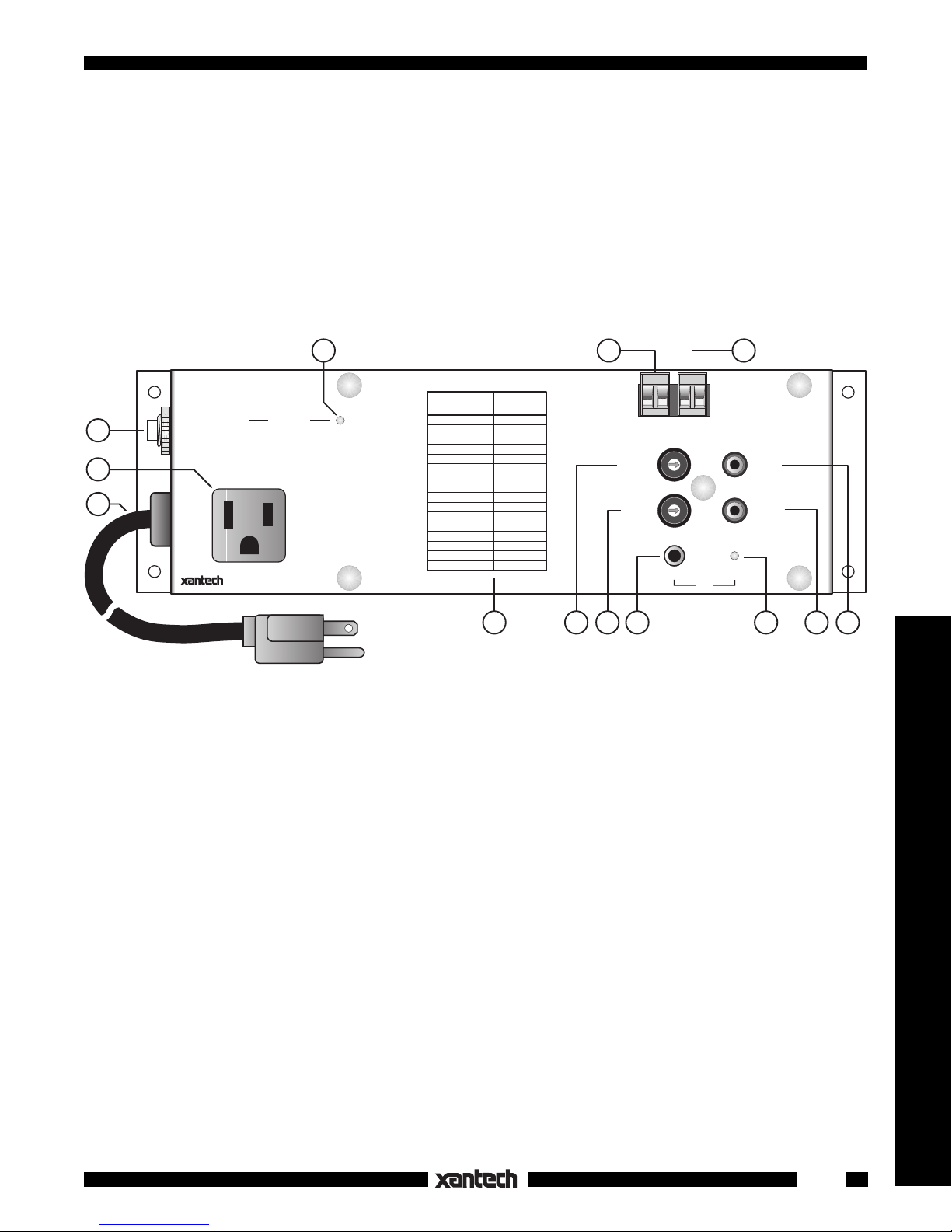
Fig. 1 The AC2
FEATURES AND SPECIFICATIONS
1. SWITCHED OUTLET: 15 Amps continuous, 30 Amps peak inrush, at 120 VAC, 60 Hz.
Standby AC Line Current: < 25 mA (< 3.0 Watts).
2. AC Power Cord: 120 VAC 16 gauge 5 ft., 3-conductor.
3. AC Circuit Breaker: Opens if AC current exceeds 15 Amps. Manual Push-to-Reset button.
4. STATUS LED. Lights when the AC Outlet is switched ON.
5. CONTROL IN AC or DC: Plug-in 2-terminal connector. 5 Volts (@ 7 mA) to 30 Volts (@ 47 mA), AC
or DC, at this input switches the AC Outlet ON, lights the STATUS LED and causes a +12V high at
the CONTROL OUT connector. Works with components that provide a continuous voltage output to
represent a power ON or other condition.
NOTE: DC voltages must be connected with polarity as shown. AC doesn't matter.
CONTROL IN Turn-OFF Voltage: <1.4 Volts.
6. CONTROL OUT: Plug-in 2-terminal connector. Delivers a constant +12 VDC output (9V @ 30 mA)
when the AC Outlet is switched ON by a control voltage, video sync or IR code. This +12 VDC can be
used to drive other voltage controlled devices, such as an AC1 or a 2nd AC2.
7. VIDEO IN. RCA type jack. Circuit senses NTSC sync at baseband video. Hi-Z input provides loss-
less loop-thru to VIDEO OUT jack. Circuit is triggered when the presence of NTSC sync represents
a power ON condition.
7
Remote Control Switchers
1
Page 2
5
OFF ON TGL MMT
OFF ON TGL MMT
OFF ON TGL MMT
OFF ON TGL MMT
OFF ON TGL MMT
OFF ON TGL MMT
OFF ON TGL MMT
OFF ON TGL MMT
0
2
3
4
5
6
1
7
80 48 10 90 01
00 C0 50 D0 41
40 A0 30 B0 21
20 E0 70 F0 61
60 88 18 98 09
08 A8 38 B8 29
28 E8 78 F8 69
68 C8 58 D8 49
E1 89 C9 A9 E9
71 19 59 39 79
F1 99 D9 B9 F9
Place the
"B" Overlay
on the RC68+
0
1
2
3
4
5
6
7
CODE
SUB-
GROUP
6
2
4
3
1
RC68+
6
B
8. VIDEO OUT. RCA type jack. Allows direct video loop-thru to a monitor, etc. Use if a 2nd video output
jack is not available on the Video source.
9. IR INPUT: 3.5mm mono mini jack accepts standard IR signals from the emitter output jacks of Xantech
Connecting Blocks, Controllers, etc. The AC2 operates with RC68+ IR commands set to code group
number 28.
10. IR INDICATOR: Flashes when any IR signal is present.
11. DELAY Switch: Provides 16 settings of delay time between the arrival of the CONTROL IN OR VIDEO
IN signal and the ON condition of the SWITCHED OUTLET. The delay times range from 0.05 second
to 60 seconds.
12. See Figs. 1 & 4 for a chart of the available DELAY times vs DELAY SWITCH POSITION. NOTE:
Delay action does not apply to the IR INPUT signal.
13. CODE SUB-GROUP Switch. Allows a choice of 8 different groups of the four RC68+ (or RC68)
commands that operate the AC2. Also, internal E2 PROM can be set to different code groups, allowing
up to 240 different IR code combinations. This prevents mutual interaction in common IR systems
when using more than one AC2 in a system.
• Mounting: Flanges, plus supplied screws, permit easy mounting to flat surfaces.
• Dimensions: 10-1/2" L x 3-1/4" W x 2-1/2" H (267mm x 83mm x 64mm)
RC68+ PROGRAMMER
The RC68+ (or RC68) Programmer (available separately) contains the commands necessary for IR
operation of the AC2.
• You will need it to program universal learning devices such as the Xantech URC-1 learning remote, the
Xantech Smart Pads, the 590 Programmable Controller, the 710 Fone Link, etc., with commands that
operate the AC2.
• NOTE: The RC68+ codes operate several other Xantech models as well, such as the RS41AV, CC12,
ZPR68, etc. Therefore, only the button descriptions that apply to the operation of the AC2 (Overlay
"B") are listed below. All others should be ignored.
CAUTION: While the RC68+ will operate as a separate remote control, it is highly recommended it not be
given to the final user for the following reasons:
• Since it includes setable code groups, the user may inadvertently alter the installer configurations.
• Also, since the user will require IR commands from other brands of
equipment to control the total system, in addition to those of the AC2, all
commands should be consolidated into one learning device, for ease of
use.
APPLICABLE RC68+ BUTTONS
1. Pair OFF Command. This button activates the IR command that turns
2. Pair ON Command. This button activates the IR command that turns
3. TGL (toggle) Command. The first press of this button turns the
4. MMT (momentary) Command. Pressing this button turns the
5. IR Emitter Lens.
the SWITCHED OUTLET OFF.
the SWITCHED OUTLET ON.
SWITCHED OUTLET ON -- the second press turns it OFF.
SWITCHED OUTLET ON but stays ON only as long as the button is
held down. When released, the SWITCHED OUTLET turns OFF.
2
Fig. 2 The RC68+ Programmer
AC2
Page 3

6. CODE SUB-GROUP
Four buttons on eight rows of the RC68+, identified by athe numbers 0 through 7 (see Fig. 2), will
execute the same set of 4 commands listed above, when selected by the CODE SUB-GROUP switch
on the AC2. This is useful to prevent mutual interaction in common IR systems when using more than
one AC2.
To change the CODE SUB-GROUP, simply rotate the CODE SUB-GROUP switch on the AC2 to
the number that corresponds to the desired row on the RC68+.
Remove power
from the AC2 for 20
to 30 seconds.
Re-apply power and use the chosen row to execute the commands for that particular AC2.
NOTE: No changes are needed on the RC68+!
7. Code Group Numbers. The AC2 is also capable of being set to different basic code groups as well
as the sub-groups.
NOTE:
When shipped from the factory, the AC2 is set to code group number 28. Be sure to
set the RC68+ to the same number!
It would only be necessary to change the AC2 to a different code group if the common IR bus system
included more than eight AC2's. The code group change would then prevent mutual interaction.
Refer to the RC68 instructions for code group setting procedures.
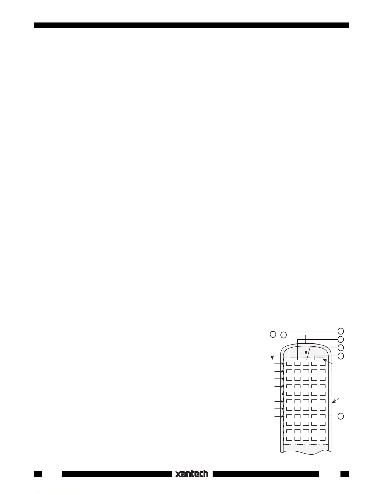
DELAY SWITCH
The AC2 allows you to delay the turn ON of the SWITCHED OUTLET over a range of 0.05 second to 60
seconds, by use of the DELAY switch (Fig. 3).
The Time Delay Chart, Fig. 4, lists the available DELAY times for each position of the DELAY SWITCH.
This allows you, for instance, (with the use of more than one AC2) to space apart the turn ON times of 2
or more high powered devices (such as large power amplifiers). This prevents high simultaneous inrush
currents from overloading AC power circuit breakers, etc.
NOTE: The DELAY is the time between the start of the CONTROL IN voltage (AC or DC) or VIDEO IN sync
and-
a) the ON state of the SWITCHED OUTLET.
b) the presence of +12 VDC at CONTROL OUT.
Remote Control Switchers
IMPORTANT: Delay action does not apply
a)
to the IR INPUT control signals.
b)
to the turn OFF condition.
Fig. 3
Delay Switch
AC2
DELAY SWITCH
POSITION
0
1
2
3
4
5
6
D
C
E
B
F
A
0
9
1
8
2
7
3
6
4
5
7
8
9
A
B
C
D
E
F
DELAY
(In Seconds)
0.05
0.1
0.2
0.3
0.5
0.75
1.0
2.0
3.0
5.0
7.5
10
20
30
50
60
Fig. 4 Time Delay Chart
3
Page 4

INSTALLATION
Because of the many ways in which it can be controlled, the AC2 offers great flexibility in providing power
ON/OFF switching of "Power Line Switchable" components for AC power management in A/V systems.
"Power Line Switchable" components are those that have manual power switches that can be left "ON" or
those that "remember" their "ON" condition when their power cords are unplugged.
Using the CONTROL IN terminals and Timed DELAY
Fig. 5 illustrates how the AC2 can be used to provide a delayed turn-on for a second power amplifier in an
audio or A/V system.
• This example makes use of the switched AC outlet on a preamp or A/V receiver.
• An unregulated DC adapter, 5 to 30 Volts output (in this case a Xantech 781C-00), is plugged into the
both
switched outlet of the preamp. The adapter output is connected to
the input of an AC1 and an AC2
as shown.
• One AC1 is used, since the power to the first amplifier can be allowed to come on immediately. It does
not need to be delayed.
• The DELAY switch of the
AC2 is set for 2.0 seconds
of delay (the #7 position).
• If more than two amplifiers
are needed, simply add
additional AC2's as
needed. Additional AC2's,
however, should have their
CONTROL IN terminals
connected to the previous
AC2's CONTROL OUT ter-
To 120 V AC
(unswitched)
786-00
Unregulated
Power
Supply
AC1
AC1
SWITCHED AC OUTLET
120 VAC 60 HZ
1800 WATTS MAX.
SWITCHED
AC Outlet on
Pre-amp, etc.
White Striped
Side
CONTROL
INPUT
+
–
5 to 30 Volts DC
minals. This permits each
delay to be set to the same
value, if desired.
To 120 V AC
(unswitched)
High Power
Amplifier #1
It is recommended that delays of at least 2 seconds be
used for this type of application. This will insure that
each turn-on current surge is
cleared before the next one
arrives.
Using the VIDEO INPUT
Fig. 6 is an example of the
use of the VIDEO INput jack
AC2
CONTROLLED AC OUTLET
SWITCHED
OUTLET
STATUS
1800 WATTS MAX.
120 VAC 60 HZ
AC2
DELAY SWITCH
POSITION
0
1
2
3
4
5
6
7
8
9
A
B
C
D
E
F
DELAY
(In Seconds)
0.05
0.1
0.2
0.3
0.5
0.75
1.0
2.0
3.0
5.0
7.5
10
20
30
50
60
CONTROL
OUT
12VDC
-- + -- +
9
8
DELAY
CODE
SUB-
GROUP
INPUT INDICATOR
CONTROL
IN
5-30V
AC or DC
C
D
E
B
F
A
0
1
2
7
3
6
4
5
7
6
5
0
4
1
3
2
VIDEO
IN
VIDEO
OUT
IR
on the AC2.
• In this case, the Video
High Power
Amplifier #2
Output of a TV monitor is
used to activate the AC2 to
turn on an external power
amplifier for high quality
audio.
Fig. 5 Using the CONTROL IN terminals and Timed Delay
4
AC2
Page 5

• It assumes that the Video Sync output of the TV monitor turns on and off with the TV's power command.
Delay action is normally not needed in a simple system like this, but can be used if deemed necessary.
• The VIDEO OUT jack can be used to feed video to another TV monitor and/or to a VCR, etc. as shown.
• Many other AC switching configurations are possible using Video sensing.
Left
Speaker
TV
MONITOR
VIDEO OUT
AUDIO OUT
Right
Speaker
L
R
Power
Amplifier
VIDEO
VIDEO
AC2
To Extra TV
Monitor, VCR,
IN
OUT
etc., if desired.
To 120 V AC
(unswitched)
Fig. 6 Using the VIDEO IN jack
AC2
CONTROLLED AC OUTLET
SWITCHED
OUTLET
Power Amp
AC Cord
STATUS
120 VAC 60 HZ
1800 WATTS MAX.
DELAY SWITCH
POSITION
0
1
2
3
4
5
6
7
8
9
A
B
C
D
E
F
DELAY
(In Seconds)
0.05
0.1
0.2
0.3
0.5
0.75
1.0
2.0
3.0
5.0
7.5
10
20
30
50
60
CONTROL
OUT
12VDC
DELAY
CODE
SUB-
GROUP
-- + -- +
CONTROL
IN
5-30V
AC or DC
C
D
E
B
F
A
0
9
1
8
2
7
3
6
4
5
6
7
5
0
4
1
3
2
INPUT INDICATOR
IR
Using the IR INPUT
Fig. 7 illustrates how the AC2 can be controlled from within an IR controlled system.
• In this example, IR signals to control the AC2, as well as the rest of the system, come from several IR
sources, as shown.
• RC68+ commands, needed to control the AC2, are "taught", where applicable, to the Smart Pad
, the 590
3
controller and a learning remote, such as the Xantech URC types.
• In this case, a 789-44 Connecting Block is used to divide the IR signal evenly between the emitters and
the IR INPUT of the AC2.
Remember, all IR signal sources connect to the INPUT (signal) side of the connecting block and all output
devices connect to the OUTPUT (emitter) side.
• Since the 590 controller is powered separately, only a 2-conductor cable is required to connect Signal (O)
and Gnd (G) to the input side of the 789-44 Connecting Block, as shown.
• Other IR signal sources, such as the Zone and Common IR outputs of the Xantech ZPR68, may be
connected in the same manner to drive the IR INPUT of the AC2.
NOTE: The power cord of the AC2 should normally be plugged into an un-switched AC outlet. However,
if the power to the AC2 is turned off by a power failure, or other cause, the internal memory will
retain the last IR selected switched condition for the outlet.
Remote Control Switchers
AC2
5
Page 6

IMPORTANT: DELAY action
does not
work with the IR INPUT terminals. If a delay is needed, simply
add it as part of a command sequence in the IR learning device.
Using all Three Inputs Simultaneously
It is possible to make simultaneous connections to the CONTROL IN, VIDEO IN and IR INPUTs in a complex
system. The AC2 responds to the three inputs in a logical "OR" fashion. That is, the SWITCHED OUTLET
will turn ON with the arrival of the first control in signal and will switch OFF only after the last control signal
is removed.
NOTE: The IR input signal will have no effect on operation as long as the CONTROL IN and VIDEO IN have
control signals present.
REMOTE ROOM
+12V
IR OUT
GND
+12V
+12 VDC
IR OUT
GND
IR OUT
780-10
J-BOX RECEIVER
IR Receiver
ST
GND
780-10
J-Box
Smart
Pad
V
+12V
GS
RCVR
GND
IR OUT
590-00
Programmable Controller
™
3
+
1
–
(back view)
2 3 4 5 6 7 8 9 10 11 14 15 16OG–+12 13
IR
"+"
REMOTE ROOM
CB12
Connecting Block
OUT
X
PWR
7 Foot Quick
Connect Cable
RES DEL SEQ PGM
12VDC
1234
BANK
12VDC
Satellite Receiver
291-10
Hidden Link™
IR Receiver
786-00
Power
Supply
To 120 V AC
(unswitched)
To 120 V AC
(unswitched)
AC2
AC2
CONTROLLED AC OUTLET
782-00
Power
Supply
SWITCHED
OUTLET
STATUS
120 VAC 60 HZ
1800 WATTS MAX.
2-Conductor
Cable
789-44
Connecting Block
12VDC
CONNECTING BLOCK
"+"
DELAY SWITCH
POSITION
0
1
2
3
4
5
6
7
8
9
A
B
C
D
E
F
+12 VDC
GND
STATUS
IR IN
RCVR
IR
(In Seconds)
DELAY
0.05
0.1
0.2
0.3
0.5
0.75
1.0
2.0
3.0
5.0
7.5
10
20
30
50
60
789-44
EMITTERS
CONTROL
OUT
12VDC
AC Switched Device
(Such as a Power Amplifier)
-- + -- +
DELAY
CODE
SUB-
GROUP
INPUT INDICATOR
283M
Blink-IR™
VCR
283M
Blink-IR™
AV Receiver
283M
Blink-IR™
Mouse Emitter
CONTROL
IN
5-30V
AC or DC
C
D
E
B
F
A
0
9
8
7
6
4
5
6
5
4
3
2
VIDEO
1
2
3
7
0
1
IN
VIDEO
OUT
IR
Fig. 7 Using the IR INPUT jack on the AC2 in an IR Controlled System
6
Rev.C
2-2-01
AC2
 Loading...